JP4635989B2 - Current interrupt device - Google Patents
Current interrupt device Download PDFInfo
- Publication number
- JP4635989B2 JP4635989B2 JP2006237193A JP2006237193A JP4635989B2 JP 4635989 B2 JP4635989 B2 JP 4635989B2 JP 2006237193 A JP2006237193 A JP 2006237193A JP 2006237193 A JP2006237193 A JP 2006237193A JP 4635989 B2 JP4635989 B2 JP 4635989B2
- Authority
- JP
- Japan
- Prior art keywords
- current
- circuit
- limiting fuse
- fuse
- short
- Prior art date
- Legal status (The legal status is an assumption and is not a legal conclusion. Google has not performed a legal analysis and makes no representation as to the accuracy of the status listed.)
- Expired - Fee Related
Links
Images
Landscapes
- Emergency Protection Circuit Devices (AREA)
- Fuses (AREA)
Description
この発明は、直流または交流の電気回路において短絡事故にともなう短絡電流のような過電流が発生した場合、この過電流を限流して速やかに遮断して、電気回路を短絡事故から保護する電流遮断装置に関する。 In the case where an overcurrent such as a short-circuit current caused by a short-circuit accident occurs in a DC or AC electric circuit, the current cut-off protects the electric circuit from a short-circuit accident by limiting the over-current and quickly shutting it off. Relates to the device.
このような電流遮断装置としては、すでに、特許文献1および2に示すような電流遮断装置がよく知られている。
As such a current interrupting device, current interrupting devices as shown in
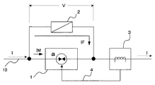
この従来から知られている電流遮断装置は、図3に示すように、電気回路の電路10中に挿入された電路遮断器1に並列に限流ヒューズ2を接続して構成される。電路遮断器1には、電路10の電流を検出する電流検出器3が付属する。電路遮断器1は、前記特許文献1および2に示すような、電路の開放を火薬類の爆発エネルギーによって行うように構成され、電流検出器3が電路10の電流が予め設定された電流以上の過電流になったことを検出したとき、電路遮断器1の図示しない電気点火装置に点火信号4を与えることにより、内蔵された火薬類を爆発させて、その爆発エネルギーにより内部通電路aを破断して電路を開放することにより、電流を遮断するものである。このため、電路遮断器1の電流遮断動作は、極めて高速で、電流検出器3が過電流を検出すると電路遮断器1はほぼ瞬時に電路10を開放し、電路の短絡電流Iを遮断する。
As shown in FIG. 3, this conventionally known current interrupting device is configured by connecting a current limiting
このような電路遮断器1は、電流遮断を高速で行うことができるが、構造上、遮断容量が制限され、これをあまり大きくすることができないので、電流容量の大きな電気回路で使用する場合は、図示するように並列に限流ヒューズ2を接続して使用する。
Such a circuit breaker 1 can cut off the current at high speed, but the structure is limited in breaking capacity and cannot be increased so much, so when used in an electric circuit having a large current capacity. The current limiting
このような電流遮断装置の電流遮断動作を、図4を参照して説明する。 The current interruption operation of such a current interruption device will be described with reference to FIG.
電路10に時点0において短絡事故が発生し、電路10を流れる短絡電流Iが図4のt0時点において、電流検出器3の過電流設定値I0のP1点に達すると、電流検出器3が
これを検知して、電路遮断器1に内部通電路aを破断する点火信号4を与える。これによって電流がI1となるP2点まで上昇したt1時点から電路遮断器1が通電路aの破断動作を開始し、この電路遮断器1に流れる電流IMが、次第に減少し、限流ヒューズ2へ流れる電流IFがP3点からP4点へ向かって上昇し始める。
When a short circuit accident occurs in the
すなわち、短絡電流Iは、電路遮断器1から限流ヒューズ2へ転流し、t2時点で電路遮断器1に流れる電流IMは0となるP5点に達し、短絡電流Iが完全に限流ヒューズ2に転流する(P4点)。
That is, the short circuit current I is commutated from the circuit breaker 1 to the current limiting
短絡電流Iが限流ヒューズ2へ転流し、限流ヒューズ2を流れる電流IFが増加を続け、限流ヒューズ2の溶断I2t値(溶断時間に対するジュール積分値)によって決まる溶断動作タイミングであるP6点(t3時点)(この時点の電流値はI5)で限流ヒューズ2の内部エレメントが溶断してアークが発生すると、この時点よりアークが消滅するまでの限流ヒューズ2の動作として、短絡電流Iは限流ヒューズ2の限流特性に従って減少を始め、限流ヒューズ2の端子電圧Vが上昇し、t4時点で、短絡電流Iが0となり(P8点)、限流ヒューズ2の両端電圧Vが電源電圧Vsとなって遮断が完了する(P9点)。
The short-circuit current I is commutated to the current-limiting
なお、限流ヒューズを構成する内部エレメントである可溶体の溶断現象は、例えば特許文献3に示されているように、特に溶断時間が5ms以下の短時間となるような大電流遮断の場合、その限流ヒューズ個有の溶断I2t値によってのみ決定されると考えることができ、流れた電流によるI2t値(電流の2乗の積分値)が溶断I2t値と等しくなったとき可溶体が溶断してアークが発生することになる。
Note that the fusing phenomenon of the fusible body, which is an internal element constituting the current limiting fuse, is, for example, as shown in
また、電気回路の電源容量が増大する等して、短絡電流Iの上昇率が増大し、短絡電流Iの変化を示す電流特性線が図4におけるIAからIBへ変化したとすると、電路遮断器1および限流ヒューズ2の動作時間は変わらないものとすれば、短絡電流Iはt1時点でI1からI2へ、t2時点でI3からI4へ、そしてt3時点でI5からI6へ増加し、特に限流ヒューズ2の内部エレメントが溶断してアークが発生する時点(t3時点)の電流が増大するので、限流ヒューズ2として必要な遮断容量も増加する。もし、短絡電流Iの増大が限流ヒューズ2の遮断容量を上回れば、短絡電流を遮断することができず、電気回路の短絡保護ができなくなる。
このように従来の電流遮断装置においては、電気回路の電源容量が増大したり、電気回路のインピーダンスまたは抵抗が低下されたりして、短絡事故の際に電流値そのもの、またはその上昇率の大きな短絡電流が発生すると、限流ヒューズの遮断容量を増加しない限り、短絡電流の遮断ができず、電気回路の保護が困難となる問題がある。 As described above, in the conventional current interrupting device, the power supply capacity of the electric circuit increases or the impedance or resistance of the electric circuit decreases, so that the current value itself or a short circuit having a large increase rate in the event of a short circuit accident. When the current is generated, unless the breaking capacity of the current limiting fuse is increased, the short-circuit current cannot be cut off, which makes it difficult to protect the electric circuit.
この発明は、このような従来装置における問題を解決して、大容量の電気回路において短絡事故が発生し、電流値の大きな短絡電流あるいは電流上昇率の大きな短絡電流が生じても、限流ヒューズの遮断容量を増加することなくこの短絡電流を遮断することのできる電流遮断装置を提供することを課題とするものである。 The present invention solves such a problem in the conventional device, and even if a short-circuit accident occurs in a large-capacity electric circuit and a short-circuit current with a large current value or a short-circuit current with a large current rise rate occurs, the current-limiting fuse It is an object of the present invention to provide a current interrupting device that can interrupt this short circuit current without increasing the interrupting capacity of the current.
このような課題を解決するため、この発明は、電路に流れる電流が過電流になったとき内部通電路を高速で遮断する電路遮断器と、この電路遮断器と並列に接続された、過電流によって内部の溶断エレメントを溶断して電流を限流して遮断する限流ヒューズとを組み合わせて構成した電流遮断装置において、前記限流ヒューズを、定格電流の小さな第1の限流ヒューズと、この第1の限流ヒューズより定格電流の大きな第2の限流ヒューズとを直列接続して構成するとともに前記第1の限流ヒューズに並列に限流用抵抗またはインピーダンスを接続したことを特徴とするものである。 In order to solve such a problem, the present invention provides a circuit breaker that cuts off the internal current path at high speed when the current flowing in the circuit becomes an overcurrent, and an overcurrent connected in parallel with the circuit breaker. In the current interrupting device configured by combining the current-limiting fuse that cuts off the internal fusing element by current-limiting and interrupting the current, the current-limiting fuse is connected to the first current-limiting fuse having a small rated current and the first current-limiting fuse. A current limiting fuse having a rated current larger than that of one current limiting fuse is connected in series, and a current limiting resistor or impedance is connected in parallel to the first current limiting fuse. is there.
この発明は、電気回路の電路中に挿入された電路遮断器と並列に直列接続された定格電流値の小さな第1の限流ヒューズと大きな第2の限流ヒューズとを接続し、前記第1の限流ヒューズに並列に限流用のインピーダンスまたは抵抗を接続して電流遮断装置を構成しているので、電路に流れる短絡電流を電路遮断器により高速で遮断することにより、短絡電流がこの電路遮断器から限流ヒューズへ転流されると、定格電流の小さい第1の限流ヒューズがより早く溶断され、短絡電流を第1の限流ヒューズからこれに並列に接続された限流用インピーダンスまたは抵抗に転流させることにより、短絡電流を限流することができ、この限流された短絡電流を第2の限流ヒューズにより遮断することができるので、限流ヒューズの遮断容量を減ずることができる。 According to the present invention, a first current limiting fuse having a small rated current value and a second current limiting fuse having a large rated current value connected in series with a circuit breaker inserted in an electric circuit of an electric circuit are connected to each other. A current interrupt device is configured by connecting a current-limiting impedance or resistor in parallel with the current-limiting fuse, so that the short-circuit current is interrupted by cutting off the short-circuit current flowing in the circuit at high speed with the circuit breaker. When the transformer is commutated to the current limiting fuse, the first current limiting fuse having a small rated current is blown earlier, and the short-circuit current is transferred from the first current limiting fuse to the current limiting impedance or resistance connected in parallel thereto. By commutating, the short-circuit current can be limited, and the limited short-circuit current can be interrupted by the second current-limiting fuse, so that the interrupting capacity of the current-limiting fuse is reduced. Door can be.
電気回路の電源容量の増大に応じて限流用インピーダンスまたは抵抗の値を調整することにより、限流量の調整ができるので、どのような電源容量を有する電気回路にでも適用することができる。 The flow rate can be adjusted by adjusting the current-limiting impedance or the resistance value in accordance with the increase in the power capacity of the electric circuit, so that the present invention can be applied to an electric circuit having any power capacity.
この発明の実施の態様を図1に示す実施例について説明する。 The embodiment of the present invention will be described with reference to the embodiment shown in FIG.
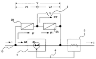
図1において、1は従来装置と同様に例えば内蔵された火薬類を爆発させて、その爆発エネルギーにより内部通電路aを破断して電路を開放し、電流を遮断するようにした高速度遮断器により構成した電路遮断器であり、電気回路の電路中に挿入される。この電路遮断器1に並列に、直列接続した定格電流値が小さく選ばれた第1の限流ヒューズ2Aと定格電流値が第1の限流ヒューズより大きく選ばれた第2の限流ヒューズ2Bとを接続する。
In FIG. 1, reference numeral 1 denotes a high-speed circuit breaker in which, for example, a built-in explosive is exploded, the internal energization path a is broken by the explosion energy to open the circuit, and the current is interrupted. It is an electric circuit breaker constituted by the above, and is inserted into the electric circuit of the electric circuit. In parallel with this circuit breaker 1, a first current limiting
ここで、定格電流値の小さい第1の限流ヒューズ2Aは、その溶断I2t値(溶断に必要なエネルギー値)が定格電流値の大きい第2の限流ヒューズ2Bの溶断I2t値(溶断に必要なエネルギー値)よりも小さいので、第2の限流ヒューズ2Bよりも早いタイミングで、流れた電流によるI2t値(電流の2乗の積分値)が溶断I2t値と等しくなって、第2の限流ヒューズ2Bよりも先に、その内部エレメントが溶断してアークが発生する。
Here, the first current limiting
そして、第1の限流ヒューズ2Aに並列に適宜の限流用抵抗を接続する。交流回路の場合は、この限流用抵抗5は限流用インピーダンスとすることもできる。
Then, an appropriate current limiting resistor is connected in parallel to the first current limiting
また、3は電路遮断器1に付属する電路10の電流を検出する電流検出器である。この電流検出器3は、電路電流が設定電流を超えて過電流になったことを検出すると、電路遮断器1に点火信号4を与る。電路遮断器1は、この点火信号により内部の火薬に点火し爆発させ、その爆発エネルギーにより内部通電路aを破断させて電路電流を高速に遮断することができる。
電路10の電流Iが通常の範囲で流れている場合は、電路遮断器1の内部通電路aは接続状態にあるので、内部抵抗が第1および第2の限流ヒューズの直列接続回路の内部抵抗よりはるかに小さいため、この電路電流Iはほとんど全部が電路遮断器1に流れ、ヒューズ2A、2Bにはほとんど流れないので、限流ヒューズ2A,2Bは長期間劣化することなく接続状態を維持する。また、限流ヒューズ2Aが接続状態にあるときは、限流用抵抗5は、これによって短絡された状態になるので、電路電流Iへ影響することがない。
When the current I of the
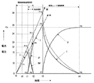
このように構成したこの発明の電流遮断装置の動作を、図2を参照して説明する。図2は、電流遮断装置内の各部の電流および電圧の時間的な変化を示すものである。 The operation of the current interrupting device of the present invention configured as described above will be described with reference to FIG. FIG. 2 shows temporal changes in current and voltage of each part in the current interrupting device.
電流遮断装置の挿入された電気回路の電路10に短絡事故が発生した状態で、この電気回路に図2の0時点で電源が投入されると、電路遮断器1に短絡電流Iが流れ始め、電気回路の電源容量、内部抵抗およびインピーダンス等の回路条件にしたがって上昇する。この電流Iが電流検出器3の設定した過電流レベルI0となるP1点(t0時点)で、電流検出器3から電路遮断器1を断路するための点火信号4が与えられる。これにより、電路遮断器1は、いくらか時間をおいたt1時点から、内部の火薬を爆発させ、そのエネルギーで内部通電路aを破断して、電流の遮断動作を開始すると、電路遮断器1を流れる電流IMが減少し、限流ヒューズ2Aと2Bの直列回路への転流が始まり、限流ヒューズ回路の電流IFが図2のP3点からP4点に向かって増加する。t2時点で電路遮断器1の内部通電路aが完全に断路し、電路遮断器1を流れる電流IMは0となるP5点へ移動し、限流ヒューズ回路を流れる電流IFが増加し、I3となるP4点へ移動し、電路10の短絡電流Iは完全に限流ヒューズ回路へ流れ、転流が完了する。
In a state where a short circuit accident has occurred in the
短絡電流Iが限流ヒューズ回路に転流し、増加を続けると、定格電流値が限流ヒューズ2Bよりも小さい限流ヒューズ2Aは、上述のように溶断I2t値も限流ヒューズ2Bより小さいことから、限流ヒューズ2Bの溶断動作タイミング(後述のP8点(t4時点))よりも早いP6点(t3時点)(この時点の電流値はI5)で内部エレメントが溶断してアークが発生し、この時点よりアークが消滅するまでの限流ヒューズ2Aの動作として、電流I=IF1が限流ヒューズ2Aの限流特性に従って減少する限流動作が開始する。これにより、短絡電流Iは限流ヒューズ2Aへ流れる電流IF1と限流用抵抗5へを流れる電流IF2とに分流し、限流ヒューズ2Aの限流動作の進行とともにIF1が減少し、IF2が増加する。
When the short-circuit current I commutates to the current-limiting fuse circuit and continues to increase, the current-limiting
このとき、限流用抵抗5は、図2に示すように短絡電流Iを所定の電流、例えば電流IBになるような抵抗値に選定すれば、短絡電流I=IFは、限流ヒューズ2Aの限流動作により減少を続ける一方、限流用抵抗5によっても抑制されて減少する。
At this time, as shown in FIG. 2, the current-limiting resistor 5 selects the short-circuit current I to a resistance value that becomes a predetermined current, for example, the current IB, so that the short-circuit current I = IF becomes the limit of the current-limiting
定格電流値が限流ヒューズ2Aよりも大きく設定された限流ヒューズ2Bは、その溶断動作タイミングであるP8点(t4時点)(この時点の電流値はI4)で内部エレメントが溶断してアークが発生し、この時点よりアークが消滅するまでの限流ヒューズ2Bの動作として、電流I=IFが限流ヒューズ2Bの限流特性に従って減少する限流動作が開始する。これにより、短絡電流はI=IFは、限流ヒューズ2Aと2Bの直列の限流動作と限流用抵抗5の限流作用とにより急速に減少して、限流ヒューズ2Aの溶断が完了するt5時点においてこの限流ヒューズ2Aの電流IF1は0となるP13点へ至る。
The current limiting
限流ヒューズ2Aが遮断したとき、短絡電流I=IFはP12点に達し、このt5時点からは限流ヒューズ2Bと限流用抵抗5の直列回路を流れるので、さらに限流され、電流IFは、限流ヒューズ2Bにおけるアークが消滅し限流動作が完了するt6時点で0となるP15点に至る。これにより、限流ヒューズ2Bの両端電圧VBが電源電圧Vsまで上昇し、短絡電流の遮断が完了する。
When the current limiting
以上の説明から明らかなように図1の電流遮断装置では、電路遮断器1に並列接続される限流ヒューズを、定格電流値の小さな限流ヒューズ2Aと、限流ヒューズ2Aより定格電流値の大きな限流ヒューズ2Bとを直列接続してなる限流ヒューズ直列回路とするとともに、限流ヒューズ2Aに並列に限流用抵抗5を接続した構成としているので、短絡事故が発生したときの電流遮断動作において、短絡電流が電路遮断器1から限流ヒューズ直列回路へ転流されると、定格電流値の小さい方の限流ヒューズ2Aの内部エレメントがより早い溶断動作タイミングのt3時点で溶断してアークが発生するように動作し、このt3時点の電流I5、すなわち、限流ヒューズ2Aの限流動作が開始する時点の電流は小さく抑えられている。そして、図1の電流遮断装置では、さらに、短絡電流を限流ヒューズ2Aからこれに並列に接続された限流用抵抗5に転流させることにより、短絡電流を限流することができる。したがって、図1の電流遮断装置では、上記のようにして限流された短絡電流を定格電流値の大きい方の限流ヒューズ2Bにより遮断することになるので、限流ヒューズ2Bの遮断責務を軽減して、より速やかな短絡電流遮断動作を行うことができる。
As is clear from the above description, in the current interrupting device of FIG. 1, the current limiting fuse connected in parallel to the circuit breaker 1 has a current limiting
このような各限流ヒューズの定格電流値等の電流仕様の選択は、例えば、一方の限流ヒューズ2Aを200アンペア型ヒューズ(定格電流200A)とすれば、他方の限流ヒューズ2Bは600アンペア型ヒューズ(定格電流600A)にするなどして、保護する電気回路の定数、状態に合わせて最適な組み合わせのヒューズを選定するようにすればよく、限流ヒューズ2Aが限流ヒューズ2Bよりも先に溶断する、すなわち限流ヒューズ2Aの溶断時間が限流ヒューズ2Bの溶断時間よりも短い、という限流ヒューズ2Aと限流ヒューズ2Bとの溶断動作の協調に必要な条件として、(限流ヒューズ2Aの溶断I2t値)<(限流ヒューズ2Bの溶断I2t値)という条件が満たされるようにすればよい。そして、各限流ヒューズの仕様の選択においては、限流ヒューズの溶断時間電流特性として、規定された溶断時間での溶断電流、すなわち溶断動作電流の仕様値に基づき、[限流ヒューズ2Aの(規定溶断時間での)溶断動作電流値]<[限流ヒューズ2Bの(規定溶断時間での)溶断動作電流値]という条件に基づいて仕様を選択してもよく、これによっても、限流ヒューズ2Aが限流ヒューズ2Bよりも先に溶断するという溶断動作の協調を行うことができる。
The selection of the current specification such as the rated current value of each current limiting fuse is, for example, when one current limiting
なお、限流ヒューズの仕様の選択においては基本的な事項であるが、上記のような溶断時間、すなわち、電流が流れ始めた瞬間から内部エレメントである可溶体が溶断してアークを発生するまでの時間だけではなく、可溶体が溶断してアークが発生した瞬間から電流が消滅するまでの時間であるアーク時間も電流遮断装置として重要であり、溶断時間とアーク時間との総和である動作時間に係る動作時間電流特性として動作I2t値(遮断I2t値)(動作時間に対するジュール積分)などを考慮することも重要である。 In addition, although it is a basic matter in selecting the specifications of the current limiting fuse, the fusing time as described above, that is, from the moment when the current starts to flow until the fusible body as the internal element melts and generates an arc. The arc time, which is the time from when the arc is generated when the fusible material melts and the current disappears, is also important as a current interrupting device, and the operating time is the sum of the fusing time and the arc time. It is also important to consider the operation I 2 t value (cut-off I 2 t value) (Joule integration with respect to the operation time) and the like as the operation time current characteristics according to the above.
また、限流用抵抗5の限流作用は上述の通りであるが、図1の構成において限流用抵抗5を設けない場合には、限流ヒューズ2Bの内部エレメントが溶断してアークが発生するt4時点で、短絡電流Iが図2におけるP16点のI6まで上昇するが、この発明では、限流用抵抗5を設けることにより、t4時点における短絡電流IをP8点のI4に抑えることができ、大幅な限流効果が得られるため、限流ヒューズ等の遮断容量を増大することなく電源容量の大きい電気回路の短絡電流を確実に遮断することができる効果が得られる。
Further, the current limiting action of the current limiting resistor 5 is as described above. However, when the current limiting resistor 5 is not provided in the configuration of FIG. 1, the internal element of the current limiting
また、この発明における電路遮断器としては、火薬により内部通電路を破断して電流遮断を行うようにした遮断器だけでなく、過電流をより高速で遮断することのできる遮断器であれば、どのような形式の遮断器でも使用することができる。 In addition, the circuit breaker in the present invention is not only a circuit breaker that breaks the internal energization path with explosives and performs a current interruption, as long as it is a circuit breaker that can interrupt an overcurrent at a higher speed. Any type of circuit breaker can be used.
1:電路遮断器
2A、2B:限流ヒューズ
3:電流検出器
5:限流用抵抗
1:
Claims (1)
Priority Applications (1)
| Application Number | Priority Date | Filing Date | Title |
|---|---|---|---|
| JP2006237193A JP4635989B2 (en) | 2006-09-01 | 2006-09-01 | Current interrupt device |
Applications Claiming Priority (1)
| Application Number | Priority Date | Filing Date | Title |
|---|---|---|---|
| JP2006237193A JP4635989B2 (en) | 2006-09-01 | 2006-09-01 | Current interrupt device |
Publications (2)
| Publication Number | Publication Date |
|---|---|
| JP2008059967A JP2008059967A (en) | 2008-03-13 |
| JP4635989B2 true JP4635989B2 (en) | 2011-02-23 |
Family
ID=39242447
Family Applications (1)
| Application Number | Title | Priority Date | Filing Date |
|---|---|---|---|
| JP2006237193A Expired - Fee Related JP4635989B2 (en) | 2006-09-01 | 2006-09-01 | Current interrupt device |
Country Status (1)
| Country | Link |
|---|---|
| JP (1) | JP4635989B2 (en) |
Families Citing this family (7)
| Publication number | Priority date | Publication date | Assignee | Title |
|---|---|---|---|---|
| JP5185181B2 (en) * | 2009-04-07 | 2013-04-17 | 日本電信電話株式会社 | Current distribution device and DC circuit breaker |
| CN101902027B (en) * | 2009-09-04 | 2013-02-13 | 中国人民解放军海军工程大学 | Arc striking type mixing current limiting fuse |
| FR3041143B1 (en) * | 2015-09-10 | 2017-10-20 | Mersen France Sb Sas | PROTECTIVE DEVICE FOR AN ELECTRICAL CIRCUIT, ELECTRIC CIRCUIT EQUIPPED WITH SUCH A DEVICE AND METHOD FOR PROTECTING SUCH AN ELECTRICAL CIRCUIT |
| WO2019092834A1 (en) | 2017-11-09 | 2019-05-16 | 三菱電機株式会社 | Dc interrupting device |
| US11646562B2 (en) | 2019-09-17 | 2023-05-09 | National University Corporation Saitama University | Devices and methods for current interrupting using current diversion path |
| CN115036193A (en) * | 2022-03-22 | 2022-09-09 | 西安中熔电气股份有限公司 | High-reliability active and passive integrated protection device |
| WO2024100775A1 (en) * | 2022-11-08 | 2024-05-16 | 株式会社オートネットワーク技術研究所 | Vehicle protection device |
Citations (3)
| Publication number | Priority date | Publication date | Assignee | Title |
|---|---|---|---|---|
| JPS6129034A (en) * | 1984-07-19 | 1986-02-08 | 三菱電機株式会社 | Current limiting breaker |
| JPS63269433A (en) * | 1987-04-25 | 1988-11-07 | Fuji Electric Co Ltd | Breaking tube for super-current limiting fuse |
| JP2005322603A (en) * | 2004-05-11 | 2005-11-17 | Hokuriku Electric Power Co Inc:The | Protective circuit for power system |
-
2006
- 2006-09-01 JP JP2006237193A patent/JP4635989B2/en not_active Expired - Fee Related
Patent Citations (3)
| Publication number | Priority date | Publication date | Assignee | Title |
|---|---|---|---|---|
| JPS6129034A (en) * | 1984-07-19 | 1986-02-08 | 三菱電機株式会社 | Current limiting breaker |
| JPS63269433A (en) * | 1987-04-25 | 1988-11-07 | Fuji Electric Co Ltd | Breaking tube for super-current limiting fuse |
| JP2005322603A (en) * | 2004-05-11 | 2005-11-17 | Hokuriku Electric Power Co Inc:The | Protective circuit for power system |
Also Published As
| Publication number | Publication date |
|---|---|
| JP2008059967A (en) | 2008-03-13 |
Similar Documents
| Publication | Publication Date | Title |
|---|---|---|
| RU2713468C2 (en) | Protective device for electric circuit, electric circuit with such device and method of protection of such electric circuit | |
| JP4635989B2 (en) | Current interrupt device | |
| JP6097301B2 (en) | Battery system and method | |
| JP4514669B2 (en) | Protection device using thermal fuse | |
| JP6186144B2 (en) | DC current interrupter | |
| JP2007043822A (en) | Overvoltage protection circuit | |
| JP2014007134A (en) | High breaking capacity fuse | |
| JP2014512789A (en) | Electrical equipment for short-circuit protection of three-phase loads in a three-phase system | |
| CN210404710U (en) | Control circuit for fusing device and vehicle | |
| JP5175893B2 (en) | Circuit breaker and circuit break control method | |
| JP2000324674A (en) | Wire harness | |
| JP2017139903A (en) | Current cutoff device | |
| JP2014177208A (en) | Vehicular power source shut-off device | |
| JP2009284581A (en) | Surge protection device | |
| US11735377B2 (en) | Protection device for an electrical circuit, electrical circuit equipped with such a device and method for protecting such an electrical circuit | |
| JP5373165B2 (en) | Circuit breaker | |
| CN113644621A (en) | Automobile circuit protection device, system and method | |
| JP2009284580A (en) | Surge protection device | |
| JPH08205411A (en) | Reverse connection protective circuit for battery | |
| CN210821842U (en) | Protection circuit system and electric vehicle | |
| JP6354212B2 (en) | Protection system for power supply circuit of electric propulsion device | |
| JP4380451B2 (en) | Bidirectional current detector | |
| CN113168980A (en) | Device for protecting an electric circuit, and electric circuit comprising such a device | |
| WO2024100773A1 (en) | Vehicular interruption control device | |
| WO2024100775A1 (en) | Vehicle protection device |
Legal Events
| Date | Code | Title | Description |
|---|---|---|---|
| A621 | Written request for application examination |
Free format text: JAPANESE INTERMEDIATE CODE: A621 Effective date: 20080715 |
|
| A977 | Report on retrieval |
Free format text: JAPANESE INTERMEDIATE CODE: A971007 Effective date: 20101021 |
|
| TRDD | Decision of grant or rejection written | ||
| A01 | Written decision to grant a patent or to grant a registration (utility model) |
Free format text: JAPANESE INTERMEDIATE CODE: A01 Effective date: 20101026 |
|
| A01 | Written decision to grant a patent or to grant a registration (utility model) |
Free format text: JAPANESE INTERMEDIATE CODE: A01 |
|
| A61 | First payment of annual fees (during grant procedure) |
Free format text: JAPANESE INTERMEDIATE CODE: A61 Effective date: 20101108 |
|
| FPAY | Renewal fee payment (event date is renewal date of database) |
Free format text: PAYMENT UNTIL: 20131203 Year of fee payment: 3 |
|
| R150 | Certificate of patent or registration of utility model |
Free format text: JAPANESE INTERMEDIATE CODE: R150 Ref document number: 4635989 Country of ref document: JP Free format text: JAPANESE INTERMEDIATE CODE: R150 |
|
| FPAY | Renewal fee payment (event date is renewal date of database) |
Free format text: PAYMENT UNTIL: 20131203 Year of fee payment: 3 |
|
| S111 | Request for change of ownership or part of ownership |
Free format text: JAPANESE INTERMEDIATE CODE: R313111 |
|
| FPAY | Renewal fee payment (event date is renewal date of database) |
Free format text: PAYMENT UNTIL: 20131203 Year of fee payment: 3 |
|
| R350 | Written notification of registration of transfer |
Free format text: JAPANESE INTERMEDIATE CODE: R350 |
|
| R250 | Receipt of annual fees |
Free format text: JAPANESE INTERMEDIATE CODE: R250 |
|
| R250 | Receipt of annual fees |
Free format text: JAPANESE INTERMEDIATE CODE: R250 |
|
| R250 | Receipt of annual fees |
Free format text: JAPANESE INTERMEDIATE CODE: R250 |
|
| R250 | Receipt of annual fees |
Free format text: JAPANESE INTERMEDIATE CODE: R250 |
|
| R250 | Receipt of annual fees |
Free format text: JAPANESE INTERMEDIATE CODE: R250 |
|
| LAPS | Cancellation because of no payment of annual fees |


