JP4635987B2 - Flow diagram editing apparatus, flow diagram editing method, and program - Google Patents
Flow diagram editing apparatus, flow diagram editing method, and program Download PDFInfo
- Publication number
- JP4635987B2 JP4635987B2 JP2006233961A JP2006233961A JP4635987B2 JP 4635987 B2 JP4635987 B2 JP 4635987B2 JP 2006233961 A JP2006233961 A JP 2006233961A JP 2006233961 A JP2006233961 A JP 2006233961A JP 4635987 B2 JP4635987 B2 JP 4635987B2
- Authority
- JP
- Japan
- Prior art keywords
- node
- arc
- flow diagram
- information
- delimiter
- Prior art date
- Legal status (The legal status is an assumption and is not a legal conclusion. Google has not performed a legal analysis and makes no representation as to the accuracy of the status listed.)
- Expired - Fee Related
Links
Images


Landscapes
- Image Generation (AREA)
Description
本発明は、既に作成されているフローダイアグラムから、上位階層のフローダイアグラムを作成するフローダイアグラム編集装置および、フローダイアグラムの編集方法、及びプログラムに関する。 The present invention relates to a flow diagram editing apparatus, a flow diagram editing method, and a program for creating an upper level flow diagram from a flow diagram that has already been created.
システム開発をする際には、システム化の対象となる業務を分析し、システムが備えるべき機能と、その機能間での情報の流れを明確にする必要がある。そのため、システムが備えるべき機能を矩形や円形、楕円形等のノードとして表し、各機能間を流れる情報を、ノード間を結ぶ矢印(アーク)で表した図であるフローダイアグラムが一般的に作成される。特許文献1には、フローダイアグラムのノードやアークの削除や移動が生じた場合に、簡単で迅速な編集、及び整形を行う技術が開示されている。 When developing a system, it is necessary to analyze the work to be systematized and clarify the functions that the system should have and the flow of information between those functions. Therefore, a flow diagram is generally created that represents the functions that the system should have as nodes such as rectangles, circles, and ellipses, and the information that flows between the functions is represented by arrows (arcs) that connect the nodes. The Patent Document 1 discloses a technique for performing simple and quick editing and shaping when a node or arc in a flow diagram is deleted or moved.
フローダイアグラムは階層構造化されて表されていることが多い。階層構造化されたフローダイアグラムにおいては、あるフローダイアグラムに記載されているノードが、それより下位階層のフローダイアグラムでは複数に分割されて表されている。そのため、下位階層のフローダイアグラムになるほど、詳細になる反面、視認性が低いものとなる。 A flow diagram is often represented in a hierarchical structure. In a hierarchically structured flow diagram, a node described in a certain flow diagram is represented by being divided into a plurality of parts in a lower-level flow diagram. Therefore, the lower the level flow diagram, the more detailed, but the lower the visibility.
一般的に、フローダイアグラムは、システム化の対象となる業務をトップダウンで分析しながら作成される。そのため、上位階層となるフローダイアグラムがまず作成される。そして、作成されたフローダイアグラムを元にして、より詳細なそれより下位階層のフローダイアグラムが作成されることになる。
しかしながら、既に作成されたフローダイアグラムから、複数のノードを集約したい要求等により、それより上位階層のフローダイアグラムを作成する場合もある。このような場合には、既に作成されているフローダイアグラムから、どのようにノードを集約するのかをユーザが決め、ユーザが手作業で上位階層のフローダイアグラムを作成する必要がある。 However, there is a case where a flow diagram of a higher hierarchy is created from a flow diagram that has already been created due to a request to aggregate a plurality of nodes. In such a case, it is necessary for the user to decide how to aggregate the nodes from the flow diagrams that have already been created, and for the user to manually create a higher-level flow diagram.
上記の作業は、人手による作業であるため、間違いが生じる可能性がある。また、比較的複雑なフローダイアグラムを分析して、集約するノードをユーザが決めるために、一般的に時間がかかる作業であり面倒である。 Since the above work is a manual work, an error may occur. Also, it is generally a time consuming and cumbersome process for a user to determine a node to be aggregated by analyzing a relatively complicated flow diagram.
本発明は上記実情に鑑みてなされたものであり、既に作成されているフローダイアグラムから、それより上位階層のフローダイアグラムを迅速且つ正確に作成するフローダイアグラム編集装置、フローダイアグラム編集方法、及びプログラムを提供することを目的とする。 The present invention has been made in view of the above circumstances, and a flow diagram editing apparatus, a flow diagram editing method, and a program for quickly and accurately creating a flow diagram of a higher hierarchy from an already created flow diagram are provided. The purpose is to provide.
本発明の第1の観点に係るフローダイアグラム編集装置は、
少なくとも1つのノードと、複数のデリミタと、2つのノードの間またはノードとデリミタの間を結ぶアークとを有するフローダイアグラムを編集するフローダイアグラム編集装置において、
フローダイアグラムに含まれるアーク毎に、アークの始点に接続されているノードまたはデリミタの識別情報と、アークの終点に接続されているノードまたはデリミタの識別情報とを対応付けて記憶するアーク情報記憶手段と、
編集対象のフローダイアグラムに含まれるノードを特定する情報を記憶するノード情報記憶手段と、
前記アーク情報記憶手段を参照して、始点にデリミタが接続されているアークがノードと他のアークとを辿りながらデリミタに到達するルートを判別し、該ルートが途中で経由するノードに共通の識別情報を設定する共通ノード設定手段と、
前記共通ノード設定手段で共通の識別情報が設定されたノードを1つのノードに集約した上位階層のフローダイアグラムを作成する上位階層ダイアグラム作成手段とを備え、
前記共通ノード設定手段は、
前記アーク情報記憶手段を参照して、始点にデリミタが接続されているアークの終点に接続されている先頭ノードを検出する先頭ノード検出手段と、
前記先頭ノード検出手段により検出された先頭ノードを特定するノード識別情報を前記ノード情報記憶手段に記憶すると共に、検出された先頭ノードに始点が接続するアークを検出し、該アークの終点がノードに接続されているかデリミタに接続されているのかを判別するノード探索処理を実行させるノード探索手段と、を備え、
前記ノード探索処理によりアークの終点がノードに接続されていると判別されたノードに対して、該ノードの識別情報を前記ノード情報記憶手段に記憶すると共に、前記ノード探索手段にノード探索処理を再実行させ、アークの終点がデリミタに接続されていると判別された場合は、前記ノード情報記憶手段に記憶されているノード識別情報で特定される各ノードに、上位階層ダイアグラム上の1つのノードを特定する共通の識別情報を設定する、
ことを特徴とする。
A flow diagram editing apparatus according to a first aspect of the present invention provides:
In a flow diagram editing apparatus for editing a flow diagram having at least one node, a plurality of delimiters, and an arc connecting two nodes or between a node and a delimiter,
Arc information storage means for storing the identification information of the node or delimiter connected to the starting point of the arc and the identification information of the node or delimiter connected to the end point of the arc in association with each arc included in the flow diagram When,
Node information storage means for storing information for specifying a node included in the flow diagram to be edited;
Referring to the arc information storage means, the route where the arc having a delimiter connected to the start point reaches the delimiter while following the node and other arcs is determined, and identification common to the nodes through which the route passes A common node setting means for setting information;
An upper hierarchy diagram creating means for creating an upper hierarchy flow diagram in which nodes having common identification information set by the common node setting means are aggregated into one node ;
The common node setting means includes:
With reference to the arc information storage means, a leading node detecting means for detecting a leading node connected to the end point of the arc having a delimiter connected to the starting point;
Node identification information for identifying the leading node detected by the leading node detection means is stored in the node information storage means, an arc connected to the detected leading node at the start point is detected, and the end point of the arc is set as the node. Node search means for executing node search processing for determining whether it is connected or connected to a delimiter,
For the node where the end point of the arc is determined to be connected to the node by the node search process, the node identification information is stored in the node information storage unit and the node search process is re-executed in the node search unit When it is determined that the end point of the arc is connected to the delimiter, one node on the upper hierarchy diagram is assigned to each node specified by the node identification information stored in the node information storage means. Set common identifying information to identify,
It is characterized by that.
また、前記共通ノード設定手段および前記上位階層ダイアグラム作成手段は、前記上位階層ダイアグラム作成手段によって作成された上位階層のフローダイアグラムの作成の元となった下位階層のフローダイアグラムに対してアークおよび/またはノードの更新処理がなされた場合に、処理を再実行して、上位階層のフローダイアグラムを更新してもよい。 Further, the common node setting means and the upper hierarchy diagram creating means may execute an arc and / or an arc and / or a lower hierarchy flow diagram from which the upper hierarchy flow diagram created by the upper hierarchy diagram creation means is created. When the node update process is performed, the process may be re-executed to update the upper-level flow diagram .
前記上位階層ダイアグラム作成手段は、
前記アーク情報記憶手段に記憶されているアークに関連する情報のうち、前記共通ノード設定手段により共通の識別情報が設定されたノード間を結ぶアークに関連する記憶情報を削除し、且つ前記アーク情報記憶手段に記憶されているノードの識別情報のうち、前記共通ノード設定手段により共通の上位ノードの識別情報が設定された各ノードの識別情報を、対応する上位ノードの識別情報に置換した上位階層用アーク情報を作成して記憶する上位階層用アーク情報記憶手段を備え、
前記上位階層用アーク情報記憶手段の記憶情報に基づいて前記上位階層のフローダイアグラムを作成してもよい。
The upper hierarchy diagram creating means includes:
Of the information related to the arc stored in the arc information storage means, the storage information related to the arc connecting the nodes for which common identification information is set by the common node setting means is deleted, and the arc information Of the node identification information stored in the storage means, the higher hierarchy in which the identification information of each node for which the common node setting information is set by the common node setting means is replaced with the identification information of the corresponding higher node An arc information storage means for higher layers for creating and storing arc information for use,
The upper hierarchy flow diagram may be created based on the storage information of the upper hierarchy arc information storage means.
本発明の第2の観点に係るフローダイアグラム編集方法は、
少なくとも1つのノードと、複数のデリミタと、2つのノードの間またはノードとデリミタの間を結ぶアークとを有するフローダイアグラムに含まれるアーク毎に、アークの始点に接続されているノードまたはデリミタの識別情報と、アークの終点に接続されているノードまたはデリミタの識別情報とを対応付けて記憶するアーク情報記憶手段と、編集対象のフローダイアグラムに含まれるノードを特定する情報を記憶するノード情報記憶手段と、を備えたコンピュータにより、フローダイアグラムを編集するフローダイアグラム編集方法において、
前記コンピュータが、前記アーク情報記憶手段を参照して、始点にデリミタが接続されているアークがノードと他のアークとを辿りながらデリミタに到達するルートを判別し、該ルートが途中で経由するノードに共通の識別情報を設定する共通ノード設定ステップと、
前記コンピュータが、前記共通ノード設定ステップで共通の識別情報が設定されたノードを1つのノードに集約した上位階層のフローダイアグラムを作成する上位階層ダイアグラム作成ステップとを備え、
前記共通ノード設定ステップは、
前記アーク情報記憶手段を参照して、始点にデリミタが接続されているアークの終点に接続されている先頭ノードを検出し、
検出した先頭ノードを特定するノード識別情報を前記ノード情報記憶手段に記憶すると共に、検出された先頭ノードに始点が接続するアークを検出し、該アークの終点がノードに接続されているかデリミタに接続されているのかを判別するノード探索処理を実行し、
前記ノード探索処理によりアークの終点がノードに接続されていると判別されたノードに対して、該ノードの識別情報を前記ノード情報記憶手段に記憶すると共に、前記ノード探索処理を再実行し、前記ノード探索処理によりアークの終点がデリミタに接続されていると判別された場合は、前記ノード情報記憶手段に記憶されているノード識別情報で特定される各ノードに、上位階層ダイアグラム上の1つのノードを特定する共通の識別情報を設定するステップである、
ことを特徴とする。
A flow diagram editing method according to a second aspect of the present invention includes:
For each arc included in the flow diagram having at least one node, a plurality of delimiters, and an arc between two nodes or between a node and a delimiter, identification of the node or delimiter connected to the starting point of the arc Arc information storage means for storing information and identification information of a node or delimiter connected to the end point of the arc in association with each other, and node information storage means for storing information for specifying a node included in the flow diagram to be edited In a flow diagram editing method for editing a flow diagram by a computer equipped with
The computer refers to the arc information storage means, determines a route in which an arc having a delimiter connected to the start point reaches the delimiter while following the node and other arcs, and a node through which the route passes A common node setting step for setting common identification information to
The computer comprises an upper layer diagram creating step of creating an upper layer flow diagram in which nodes having common identification information set in the common node setting step are aggregated into one node;
The common node setting step includes:
Referring to the arc information storage means, detecting the head node connected to the end point of the arc to which the delimiter is connected to the start point,
Node identification information for identifying the detected head node is stored in the node information storage means, and an arc connecting to the detected head node at the start point is detected, and whether the end point of the arc is connected to the node is connected to the delimiter Execute node search process to determine whether
To the node end points of the arc by the node search processing it is judged to be connected to the node, the co when storing identification information of the node to the node information storing means, rerun the node search processing When it is determined that the end point of the arc is connected to the delimiter by the node search process, each node specified by the node identification information stored in the node information storage unit is displayed on the upper hierarchy diagram. A step of setting common identification information for specifying one node;
It is characterized by that.
本発明の第3の観点に係るプログラムは、
コンピュータを、
少なくとも1つのノードと、複数のデリミタと、2つのノードの間またはノードとデリミタの間を結ぶアークとを有するフローダイアグラムに含まれるアーク毎に、アークの始点に接続されているノードまたはデリミタの識別情報と、アークの終点に接続されているノードまたはデリミタの識別情報とを対応付けて記憶するアーク情報記憶手段と、
編集対象のフローダイアグラムに含まれるノードを特定する情報を記憶するノード情報記憶手段と、
前記アーク情報記憶手段を参照して、始点にデリミタが接続されているアークがノードと他のアークとを辿りながらデリミタに到達するルートを判別し、該ルートが途中で経由するノードに共通の識別情報を設定する共通ノード設定手段と、
前記共通ノード設定手段で共通の識別情報が設定されたノードを1つのノードに集約した上位階層のフローダイアグラムを作成する上位階層ダイアグラム作成手段と、
して機能させ、
前記共通ノード設定手段は、
前記アーク情報記憶手段を参照して、始点にデリミタが接続されているアークの終点に接続されている先頭ノードを検出する先頭ノード検出手段と、
前記先頭ノード検出手段により検出された先頭ノードを特定するノード識別情報を前記ノード情報記憶手段に記憶すると共に、検出された先頭ノードに始点が接続するアークを検出し、該アークの終点がノードに接続されているかデリミタに接続されているのかを判別するノード探索処理を実行させるノード探索手段と、を備え、
前記ノード探索処理によりアークの終点がノードに接続されていると判別されたノードに対して、該ノードの識別情報を前記ノード情報記憶手段に記憶すると共に、前記ノード探索手段にノード探索処理を再実行させ、アークの終点がデリミタに接続されていると判別された場合は、前記ノード情報記憶手段に記憶されているノード識別情報で特定される各ノードに、上位階層ダイアグラム上の1つのノードを特定する共通の識別情報を設定する、
ことを特徴とする。
The program according to the third aspect of the present invention is:
Computer
For each arc included in the flow diagram having at least one node, a plurality of delimiters, and an arc between two nodes or between a node and a delimiter, identification of the node or delimiter connected to the starting point of the arc Arc information storage means for storing information and identification information of a node or delimiter connected to the end point of the arc in association with each other;
Node information storage means for storing information for specifying a node included in the flow diagram to be edited;
Referring to the arc information storage means, the route where the arc having a delimiter connected to the starting point reaches the delimiter while following the node and other arcs is determined, and the common identification of the node through which the route passes A common node setting means for setting information;
An upper hierarchy diagram creating means for creating an upper hierarchy flow diagram in which nodes having common identification information set by the common node setting means are aggregated into one node;
To function ,
The common node setting means includes:
With reference to the arc information storage means, a leading node detecting means for detecting a leading node connected to the end point of the arc having a delimiter connected to the starting point;
Node identification information for identifying the leading node detected by the leading node detection means is stored in the node information storage means, an arc connected to the detected leading node at the start point is detected, and the end point of the arc is set as the node. Node search means for executing a node search process for determining whether it is connected or connected to a delimiter,
For the node where the end point of the arc is determined to be connected to the node by the node search process, the node identification information is stored in the node information storage means, and the node search process is re-executed in the node search means. When it is determined that the end point of the arc is connected to the delimiter, one node on the upper hierarchy diagram is assigned to each node specified by the node identification information stored in the node information storage means. Set common identifying information to identify,
It is characterized by that .
本発明によれば、既に作成されているフローダイアグラムからそれより上位階層のフローダイアグラムを迅速且つ正確に作成することが可能になる。 According to the present invention, it is possible to quickly and accurately create a higher-level flow diagram from an already created flow diagram.
以下、本発明の実施の形態に係るフローダイアグラム編集装置10について図面を用いて詳細に説明する。 Hereinafter, a flow diagram editing apparatus 10 according to an embodiment of the present invention will be described in detail with reference to the drawings.
本発明の実施の形態に係るフローダイアグラム編集装置10は、図1に示すように、操作部11と表示部12と主記憶部13と外部記憶部14と制御部15とを備える。
As shown in FIG. 1, the flow diagram editing apparatus 10 according to the embodiment of the present invention includes an
操作部11は、キーボードやマウス等から構成され、フローダイアグラムを編集したり、様々な情報を入力したりするために使用する。表示部12は、ディスプレイ等からなり、フローダイアグラムや様々な情報の表示を行う。
The
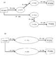
ここで、フローダイアグラム編集装置10によって編集されるフローダイアグラムについて説明する。図5(A)にフローダイアグラムの例を示す。フローダイアグラムは、デリミタとノードとアークとから構成される図である。デリミタは、アークの入力元または、出力先となるものである。ノードは、入力元となるデリミタから出力先となるデリミタへと向かうアークの途中で、節となるものである。アークは、ノードとノード、又はノードとデリミタとを結ぶ矢印である。システム開発をする際の業務分析過程において、システム化の対象となる業務の処理をノードで、該処理間でやりとりされる情報をアークで、情報の入力元、出力先をデリミタで表したフローダイアグラムを作成すれば、業務の情報の流れを図示することが可能となる。 Here, the flow diagram edited by the flow diagram editing apparatus 10 will be described. FIG. 5A shows an example of a flow diagram. The flow diagram is a diagram composed of delimiters, nodes, and arcs. The delimiter is an input source or output destination of the arc. A node is a node in the middle of an arc from an input source delimiter to an output destination delimiter. An arc is an arrow connecting nodes and nodes or nodes and delimiters. In the business analysis process during system development, a flow diagram that shows the processing of the business to be systematized as nodes, the information exchanged between the processing as arcs, and the information input source and output destination as delimiters Can be used to illustrate the flow of business information.
図1に戻り、主記憶部13は、RAM(Random Access Memory)等から構成され、制御部15が処理を実行する際の作業領域となる。
Returning to FIG. 1, the
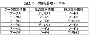
外部記憶部14は、ハードディスク装置等から構成され、制御部15が動作するために必要な各種プログラムや、編集したフローダイアグラム等を格納する。また、外部記憶部14は、図2、図3および図4に示すような構成のアーク情報管理テーブル141とノード情報管理テーブル142および、上位階層用アーク情報管理テーブル143とを記憶する。
The
図2に示すアーク情報管理テーブル141は、フローダイアグラムを構成する各アークの始点に接続されているオブジェクト(ノードかデリミタ)の識別情報(始点識別情報)と、各アークの終点に接続されているオブジェクトの識別情報(終点識別情報)とを、各アークの識別情報(アーク識別情報)毎に対応付けて記憶する。 The arc information management table 141 shown in FIG. 2 is connected to identification information (start point identification information) of an object (node or delimiter) connected to the start point of each arc constituting the flow diagram, and to the end point of each arc. Object identification information (end point identification information) is stored in association with each arc identification information (arc identification information).
図3に示すノード情報管理テーブル142は、フローダイアグラムを構成する各ノードを集約するために使われる集約識別情報を、各ノードの識別情報(ノード識別情報)毎に対応付けて記憶する。 The node information management table 142 shown in FIG. 3 stores aggregate identification information used for aggregating each node constituting the flow diagram in association with each node identification information (node identification information).
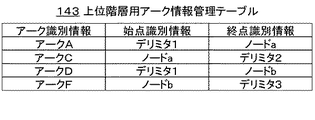
図4に示す上位階層用アーク情報管理テーブル143は、後述する上位階層フローダイアグラム作成処理によって作成される。上位階層用アーク情報管理テーブル143は、上位階層のフローダイアグラムを構成する各アークの始点に接続されているオブジェクト(ノードかデリミタ)の識別情報(始点識別情報)と、各アークの終点に接続されているオブジェクトの識別情報(終点識別情報)とを、各アークの識別情報(アーク識別情報)毎に対応付けて記憶する。 The upper layer arc information management table 143 shown in FIG. 4 is created by an upper layer flow diagram creation process described later. The upper layer arc information management table 143 is connected to the identification information (start point identification information) of the object (node or delimiter) connected to the start point of each arc constituting the upper layer flow diagram, and to the end point of each arc. The object identification information (end point identification information) is stored in association with each arc identification information (arc identification information).
図1に戻り、制御部15は、外部記憶部14に予め記憶されているプログラムを読み出して実行することにより、フローダイアグラム編集装置10全体の動作を制御する。また、制御部15は、既に作成されているフローダイアグラムから、上位階層のフローダイアグラムを作成する処理を行う。該処理の詳細については後述する。
Returning to FIG. 1, the
次に、フローダイアグラム編集装置10が、既に作成されているフローダイアグラムから、それより上位階層のフローダイアグラムを作成する処理(上位階層フローダイアグラム作成処理)の動作について説明する。 Next, the operation of a process (upper layer flow diagram creation process) in which the flow diagram editing apparatus 10 creates a flow diagram of a higher hierarchy from an already created flow diagram will be described.
前提として、外部記憶部14には、所定のフローダイアグラム及び、該フローダイアグラムに対応するアーク情報管理テーブル141とノード情報管理テーブル142とが記憶されているものとする。但し、ノード情報管理テーブル142の集約識別情報には、未だ何も記憶されていない状態である。
As a premise, it is assumed that the
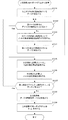
ユーザは、操作部11を操作する等して、外部記憶部14に記憶されている所定のフローダイアグラムから、上位階層のフローダイアグラムを作成するための指示情報を入力する。そして、該指示情報が制御部15に送信されたとき、制御部15は図6のフローチャートに示すような上位階層フローダイアグラム作成処理を行う。
The user inputs instruction information for creating a higher-level flow diagram from a predetermined flow diagram stored in the
まず、制御部15は、アーク情報管理テーブル141を参照して、始点がデリミタに接続されているアークを検出し(ステップS101)、ステップS102に処理を移す。
First, the
ステップS102で制御部15は、アーク情報管理テーブル141を参照して、ステップS101又は後述するステップS104又は後述するステップS107で検出したアークの終点に、デリミタが接続されているか否かを判断する。
In step S102, the
アークの終点にデリミタが接続されていないと判断したときは(S102;No)、制御部15は、該アークの終点に接続されているノードの識別情報をアーク情報管理テーブル141から取得し、該ノードの識別情報を主記憶部13に記憶する(ステップS103)。そして、制御部15は、該ノードに始点が接続されているアークを、アーク情報管理テーブル141を参照して検出し(ステップS104)、ステップS102に処理を移す。
When determining that the delimiter is not connected to the end point of the arc (S102; No), the
アークの終点にデリミタが接続されていると判断したときは(ステップS102;Yes)、制御部15は、主記憶部13に記憶されているノードの識別情報が記憶されているノード情報管理テーブル142の各エントリに、共通の集約識別情報を設定し(ステップS105)、ステップS106に処理を移す。
When it is determined that a delimiter is connected to the end point of the arc (step S102; Yes), the
ステップS106で、制御部15は、ステップS103の処理によって、主記憶部13に記憶したノードの識別情報を全て消去し、ステップS107に処理を移す。
In step S106, the
ステップS107で、制御部15は、アーク情報管理テーブル141を参照して、始点がデリミタに接続されているアークが他にないかを判断する。そして、そのようなアークがある場合は(ステップS107;Yes)、ステップS102に処理を移し、そのようなアークがない場合は(ステップS107;No)、ステップS108に処理を移す。
In step S107, the
ステップS108で、制御部15は、アーク情報管理テーブル141および、ステップS105の処理により、集約識別情報が設定されたノード情報管理テーブル142から、上位階層用アーク情報管理テーブル143を作成する。
In step S108, the
具体的には、まず、制御部15は、既に作成されているフローダイアグラムに対応するアーク情報管理テーブル141を外部記憶部14の別の領域に上位階層用アーク情報管理テーブル143としてコピーする。そして、制御部15は、コピーした上位階層用アーク情報管理テーブル143に記憶されているエントリのうち、始点識別情報および終点識別情報にステップS105の処理により共通の集約識別情報が設定されたノードの識別情報が設定されているエントリを削除する。次に、制御部15は、上位階層用アーク情報管理テーブル143内の始点識別情報及び、終点識別情報として記憶されているノードの識別情報のうち、共通の集約識別情報が設定されているノードの識別情報を、同一の上位ノードの識別情報となるように更新する。以上で、上位階層用アーク情報管理テーブル143が完成する。
Specifically, first, the
次に、制御部15は、ステップS108で作成した上位階層用アーク情報管理テーブル143から上位階層のフローダイアグラムを作成して、表示部12に表示する(ステップS109)。
Next, the
続いて、図5(A)に示すようなフローダイアグラム及び該フローダイアグラムに対応した図2に示すようなアーク情報管理テーブル141が、外部記憶部14に記憶されている場合における、該フローダイアグラムの上位階層のフローダイアグラムを作成する処理の動作を具体的に説明する。
Subsequently, when the flow diagram as shown in FIG. 5A and the arc information management table 141 as shown in FIG. 2 corresponding to the flow diagram are stored in the
まず、処理を開始すると、制御部15はアーク情報管理テーブル141を参照して、始点がデリミタに接続されているアークAを検出する(ステップS101)。
First, when the process is started, the
アーク情報管理テーブル141を参照して、アークAの終点にはデリミタが接続されていないので(ステップS102;No)、制御部15は、アークAの終点に接続されているノード1の識別情報を取得して、主記憶部13に記憶する(ステップS103)。
With reference to the arc information management table 141, since the delimiter is not connected to the end point of the arc A (step S102; No), the
次に制御部15は、ノード1に始点が接続されているアークBをアーク情報管理テーブル141より検出する(ステップS104)。
Next, the
アーク情報管理テーブル141を参照して、アークBの終点にはデリミタが接続されていないので(ステップS102;No)、制御部15は、アークBの終点に接続されているノード2の識別情報を取得して、主記憶部13に記憶する(ステップS103)。
Since the delimiter is not connected to the end point of the arc B with reference to the arc information management table 141 (step S102; No), the
次に制御部15は、ノード2に始点が接続されているアークCをアーク情報管理テーブル141より検出する(ステップS104)。
Next, the
アーク情報管理テーブル141を参照して、アークCの終点にはデリミタ2が接続されているため(ステップS102;Yes)、制御部15は、主記憶部13に記憶したノード1とノード2の識別情報に対応するノード情報管理テーブル142のエントリに、共通の集約識別情報を設定する(ステップS105)。
Since the delimiter 2 is connected to the end point of the arc C with reference to the arc information management table 141 (step S102; Yes), the
次に制御部15は、主記憶部13に記憶したノード1とノード2の識別情報を消去する(ステップS106)。
Next, the
次に制御部15は、アーク情報管理テーブル141より始点がデリミタに接続されているアークDを検出する(ステップS107;Yes)。
Next, the
アーク情報管理テーブル141を参照して、アークDの終点にはデリミタが接続されていないので(ステップS102;No)、制御部15は、アークDの終点に接続されているノード3の識別情報を取得して、主記憶部13に記憶する(ステップS103)。
With reference to the arc information management table 141, since the delimiter is not connected to the end point of the arc D (step S102; No), the
次に制御部15は、ノード3に始点が接続されているアークEをアーク情報管理テーブル141より検出する(ステップS104)。
Next, the
アーク情報管理テーブル141を参照して、アークEの終点にはデリミタが接続されていないので(ステップS102;No)、制御部15は、アークEの終点に接続されているノード4の識別情報を取得して、主記憶部13に記憶する(ステップS103)。
Since the delimiter is not connected to the end point of the arc E with reference to the arc information management table 141 (step S102; No), the
次に制御部15は、ノード4に始点が接続されているアークFをアーク情報管理テーブル141より検出する(ステップS104)。
Next, the
アーク情報管理テーブル141を参照して、アークFの終点にはデリミタ3が接続されているため(ステップS102;Yes)、制御部15は、主記憶部13に記憶したノード3とノード4の識別情報に対応するノード情報管理テーブル142のエントリに、共通の集約識別情報を設定する(ステップ105)。ここまでの処理により、ノード情報管理テーブル142は、図3に示すように、
ノード1とノード2及び、ノード3とノード4に、それぞれ共通の集約識別情報が設定された状態になる。
Since the delimiter 3 is connected to the end point of the arc F with reference to the arc information management table 141 (step S102; Yes), the
Nodes 1 and 2 and nodes 3 and 4 are set with common aggregate identification information.
次に制御部15は、主記憶部13に記憶したノード3とノード4の識別情報を消去する(ステップS106)。
Next, the
アーク情報管理テーブル141を参照して、始点がデリミタに接続されているアークはもうないため(ステップS107;No)、制御部15は上位階層用アーク情報管理テーブル143を作成する(ステップS108)。
With reference to the arc information management table 141, since there is no more arc whose starting point is connected to the delimiter (step S107; No), the
具体的にステップS108の処理について、図7を参照して説明する。
まず、制御部15は、既に作成されているフローダイアグラムに対応する図2に示すアーク情報管理テーブル141を外部記憶部14の別の領域に上位階層用アーク情報管理テーブル143として、図7(A)に示すようにコピーする。そして、制御部15は、コピーした上位階層用アーク情報管理テーブル143に記憶されているエントリのうち、ステップS105の処理により共通の集約識別情報が設定されたノード1とノード2がそれぞれ始点識別情報と終点識別情報に設定されているアークBのエントリを図7(B)に示すように削除する。同様に制御部15は、上位階層用アーク情報管理テーブル143に記憶されているエントリのうち、S105の処理により共通の集約識別情報が設定されたノード3とノード4がそれぞれ始点識別情報と終点識別情報に設定されているアークEのエントリを図7(C)に示すように削除する。次に制御部15は、始点識別情報及び、終点識別情報として記憶されているノードの識別情報のうち、共通の集約識別情報が設定されているノード1とノード2の識別情報を、同一のノードの識別情報(ノードaの識別情報)に更新する(図7(D))。同様に、制御部15は、始点識別情報及び、終点識別情報として記憶されているノードの識別情報のうち、共通の集約識別情報が設定されているノード3とノード4の識別情報を、同一のノードの識別情報(ノードbの識別情報)に更新する(図7(E))。以上のようにして、上位階層用アーク情報管理テーブル143が、図4に示すように作成される。
Specifically, the processing in step S108 will be described with reference to FIG.
First, the
次に、制御部15は、先ほど作成した上位階層用アーク情報管理テーブル143から、図5(B)に示すような上位階層のフローダイアグラムを作成し、それを表示部12に表示する。
Next, the
このように、本発明の実施の形態に係るフローダイアグラム編集装置10は、既に作成されているフローダイアグラムから、その上位階層のフローダイアグラムを作成する際に、集約するノードを決定し、それに基づいてノードを集約した上位階層のフローダイアグラムを作成することが可能となる。 As described above, the flow diagram editing apparatus 10 according to the embodiment of the present invention determines a node to be aggregated when creating a flow diagram of an upper hierarchy from a flow diagram that has already been created, and based on the determination. It is possible to create a higher-level flow diagram that aggregates nodes.
なお、この発明は上記実施形態に限定されず、種々の変形及び応用が可能である。 In addition, this invention is not limited to the said embodiment, A various deformation | transformation and application are possible.
例えば、上記実施の形態では、上位階層のフローダイアグラムの作成に応答して、ノード管理情報テーブル142の集約識別情報を設定したが、元のフローダイアグラムを作成したときに、集約識別情報を設定しても良い。そのようにすることで、上位階層のフローダイアグラムを作成するときに、既にノード管理情報テーブル142の集約識別情報は設定されているために、より迅速に上位階層のフローダイアグラムを作成することができる。 For example, in the above embodiment, the aggregate identification information of the node management information table 142 is set in response to the creation of the higher-level flow diagram. However, when the original flow diagram is created, the aggregate identification information is set. May be. By doing so, when creating a higher-level flow diagram, the aggregate identification information of the node management information table 142 is already set, so that a higher-level flow diagram can be created more quickly. .
また、上位階層と下位階層のフローダイアグラムが作成された後、下位階層のフローダイアグラムに対してアークやノードの削除、変形処理がなされた場合にも、同様に、上位階層のフローダイアグラム作成処理を行うようにして、上位階層のフローダイアグラムを更新するようにしてもよい。そのようにすることで、下位階層のフローダイアグラムの編集によって、上位階層のフローダイアグラムとの整合性が合わなくなることを防止することができる。 Similarly, when an arc or node is deleted or transformed in a lower-level flow diagram after the upper-level and lower-level flow diagrams have been created, the higher-level flow diagram creation processing is performed in the same way. You may make it update the flow diagram of an upper hierarchy as it does. By doing so, it is possible to prevent the consistency with the flow diagram of the upper hierarchy from being lost by editing the flow diagram of the lower hierarchy.
また、上記実施の形態では、上位階層のフローダイアグラムを作成するときに、上位階層用アーク情報管理テーブル143を作成し、作成した上位階層用アーク情報管理テーブル143から上位階層のフローダイアグラムを作成した。しかし、例えば、既存の下位階層のフローダイアグラムのアーク情報管理テーブル141および、集約識別情報が設定されたノード管理情報テーブル142から直接上位階層のフローダイアグラムを作成してもよい。 Further, in the above embodiment, when creating an upper hierarchy flow diagram, an upper hierarchy arc information management table 143 is created, and an upper hierarchy flow diagram is created from the created upper hierarchy arc information management table 143. . However, for example, an upper hierarchy flow diagram may be created directly from the arc information management table 141 of the existing lower hierarchy flow diagram and the node management information table 142 in which the aggregate identification information is set.
また、上記実施の形態にかかるフローダイアグラム編集装置10は、専用装置によって実現可能なことはもとより、汎用のコンピュータシステムによって構成することもできる。この場合、上記各処理を実現するためのプログラムを汎用コンピュータシステムにインストールしてOSとの協働により実行することで、汎用コンピュータ装置を、上記フローダイアグラム編集装置10として機能させることができる。 In addition, the flow diagram editing apparatus 10 according to the above embodiment can be configured by a general-purpose computer system as well as realized by a dedicated apparatus. In this case, a general-purpose computer device can be caused to function as the flow diagram editing device 10 by installing a program for realizing each of the above processes in a general-purpose computer system and executing the program in cooperation with the OS.
そして、上述の機能を実現するプログラムの提供方法は任意であり、CD−ROMなどの記録媒体に格納して提供可能なことはもとより、例えば、インターネットなどの通信媒体を介して提供してもよい。 The method for providing the program for realizing the functions described above is arbitrary, and may be provided via a communication medium such as the Internet as well as being provided by being stored in a recording medium such as a CD-ROM. .
10 フローダイアグラム編集装置
11 操作部
12 表示部
13 主記憶部
14 外部記憶部
15 制御部
141 アーク情報管理テーブル
142 ノード情報管理テーブル
143 上位階層用アーク情報管理テーブル
DESCRIPTION OF SYMBOLS 10 Flow
Claims (5)
フローダイアグラムに含まれるアーク毎に、アークの始点に接続されているノードまたはデリミタの識別情報と、アークの終点に接続されているノードまたはデリミタの識別情報とを対応付けて記憶するアーク情報記憶手段と、
編集対象のフローダイアグラムに含まれるノードを特定する情報を記憶するノード情報記憶手段と、
前記アーク情報記憶手段を参照して、始点にデリミタが接続されているアークがノードと他のアークとを辿りながらデリミタに到達するルートを判別し、該ルートが途中で経由するノードに共通の識別情報を設定する共通ノード設定手段と、
前記共通ノード設定手段で共通の識別情報が設定されたノードを1つのノードに集約した上位階層のフローダイアグラムを作成する上位階層ダイアグラム作成手段とを備え、
前記共通ノード設定手段は、
前記アーク情報記憶手段を参照して、始点にデリミタが接続されているアークの終点に接続されている先頭ノードを検出する先頭ノード検出手段と、
前記先頭ノード検出手段により検出された先頭ノードを特定するノード識別情報を前記ノード情報記憶手段に記憶すると共に、検出された先頭ノードに始点が接続するアークを検出し、該アークの終点がノードに接続されているかデリミタに接続されているのかを判別するノード探索処理を実行させるノード探索手段と、を備え、
前記ノード探索処理によりアークの終点がノードに接続されていると判別されたノードに対して、該ノードの識別情報を前記ノード情報記憶手段に記憶すると共に、前記ノード探索手段にノード探索処理を再実行させ、アークの終点がデリミタに接続されていると判別された場合は、前記ノード情報記憶手段に記憶されているノード識別情報で特定される各ノードに、上位階層ダイアグラム上の1つのノードを特定する共通の識別情報を設定する、
ことを特徴とするフローダイアグラム編集装置。 In a flow diagram editing apparatus for editing a flow diagram having at least one node, a plurality of delimiters, and an arc connecting two nodes or between a node and a delimiter,
Arc information storage means for storing the identification information of the node or delimiter connected to the starting point of the arc and the identification information of the node or delimiter connected to the end point of the arc in association with each arc included in the flow diagram When,
Node information storage means for storing information for specifying a node included in the flow diagram to be edited;
Referring to the arc information storage means, the route where the arc having a delimiter connected to the starting point reaches the delimiter while following the node and other arcs is determined, and the common identification of the node through which the route passes A common node setting means for setting information;
An upper hierarchy diagram creating means for creating an upper hierarchy flow diagram in which nodes having common identification information set by the common node setting means are aggregated into one node;
The common node setting means includes:
With reference to the arc information storage means, a leading node detecting means for detecting a leading node connected to the end point of the arc having a delimiter connected to the starting point;
Node identification information for identifying the leading node detected by the leading node detection means is stored in the node information storage means, an arc connected to the detected leading node at the start point is detected, and the end point of the arc is set as the node. Node search means for executing a node search process for determining whether it is connected or connected to a delimiter,
For the node where the end point of the arc is determined to be connected to the node by the node search process, the node identification information is stored in the node information storage means, and the node search process is re-executed in the node search means. When it is determined that the end point of the arc is connected to the delimiter, one node on the upper hierarchy diagram is assigned to each node specified by the node identification information stored in the node information storage means. Set common identifying information to identify,
A flow diagram editing device characterized by that.
ことを特徴とする請求項1に記載のフローダイアグラム編集装置。 The common node setting means and the upper hierarchy diagram creating means include an arc and / or a node for the lower hierarchy flow diagram that is the basis for creating the upper hierarchy flow diagram created by the upper hierarchy diagram creating means. When the update process is done , re-execute the process and update the upper level flow diagram .
The flow diagram editing apparatus according to claim 1.
前記アーク情報記憶手段に記憶されているアークに関連する情報のうち、前記共通ノード設定手段により共通の識別情報が設定されたノード間を結ぶアークに関連する記憶情報を削除し、且つ前記アーク情報記憶手段に記憶されているノードの識別情報のうち、前記共通ノード設定手段により共通の上位ノードの識別情報が設定された各ノードの識別情報を、対応する上位ノードの識別情報に置換した上位階層用アーク情報を作成して記憶する上位階層用アーク情報記憶手段を備え、
前記上位階層用アーク情報記憶手段の記憶情報に基づいて前記上位階層のフローダイアグラムを作成する、
ことを特徴とする、請求項1又は2に記載のフローダイアグラム編集装置。 The upper hierarchy diagram creating means includes:
Of the information related to the arc stored in the arc information storage means, the storage information related to the arc connecting the nodes for which common identification information is set by the common node setting means is deleted, and the arc information Of the node identification information stored in the storage means, the higher hierarchy in which the identification information of each node for which the common node setting information is set by the common node setting means is replaced with the identification information of the corresponding higher node An arc information storage means for higher layers for creating and storing arc information for use,
Creating the upper hierarchy flow diagram based on the storage information of the upper hierarchy arc information storage means;
The flow diagram editing apparatus according to claim 1 or 2, wherein
前記コンピュータが、前記アーク情報記憶手段を参照して、始点にデリミタが接続されているアークがノードと他のアークとを辿りながらデリミタに到達するルートを判別し、該ルートが途中で経由するノードに共通の識別情報を設定する共通ノード設定ステップと、
前記コンピュータが、前記共通ノード設定ステップで共通の識別情報が設定されたノードを1つのノードに集約した上位階層のフローダイアグラムを作成する上位階層ダイアグラム作成ステップとを備え、
前記共通ノード設定ステップは、
前記アーク情報記憶手段を参照して、始点にデリミタが接続されているアークの終点に接続されている先頭ノードを検出し、
検出した先頭ノードを特定するノード識別情報を前記ノード情報記憶手段に記憶すると共に、検出された先頭ノードに始点が接続するアークを検出し、該アークの終点がノードに接続されているかデリミタに接続されているのかを判別するノード探索処理を実行し、
前記ノード探索処理によりアークの終点がノードに接続されていると判別されたノードに対して、該ノードの識別情報を前記ノード情報記憶手段に記憶すると共に、前記ノード探索処理を再実行し、前記ノード探索処理によりアークの終点がデリミタに接続されていると判別された場合は、前記ノード情報記憶手段に記憶されているノード識別情報で特定される各ノードに、上位階層ダイアグラム上の1つのノードを特定する共通の識別情報を設定するステップである、
ことを特徴とするフローダイアグラム編集方法。 For each arc included in the flow diagram having at least one node, a plurality of delimiters, and an arc between two nodes or between a node and a delimiter, identification of the node or delimiter connected to the starting point of the arc Arc information storage means for storing information and identification information of a node or delimiter connected to the end point of the arc in association with each other, and node information storage means for storing information for specifying a node included in the flow diagram to be edited In a flow diagram editing method for editing a flow diagram by a computer equipped with
The computer refers to the arc information storage means, determines a route in which an arc having a delimiter connected to the start point reaches the delimiter while following the node and other arcs, and a node through which the route passes A common node setting step for setting common identification information to
The computer comprises an upper layer diagram creating step of creating an upper layer flow diagram in which nodes having common identification information set in the common node setting step are aggregated into one node;
The common node setting step includes:
Referring to the arc information storage means, detecting the head node connected to the end point of the arc to which the delimiter is connected to the start point,
Node identification information for identifying the detected head node is stored in the node information storage means, and an arc connecting to the detected head node at the start point is detected, and whether the end point of the arc is connected to the node is connected to the delimiter Execute node search process to determine whether
To the node end points of the arc by the node search processing it is judged to be connected to the node, the co when storing identification information of the node to the node information storing means, rerun the node search processing When it is determined that the end point of the arc is connected to the delimiter by the node search process, each node specified by the node identification information stored in the node information storage unit is displayed on the upper hierarchy diagram. A step of setting common identification information for specifying one node;
A flow diagram editing method characterized by this.
少なくとも1つのノードと、複数のデリミタと、2つのノードの間またはノードとデリミタの間を結ぶアークとを有するフローダイアグラムに含まれるアーク毎に、アークの始点に接続されているノードまたはデリミタの識別情報と、アークの終点に接続されているノードまたはデリミタの識別情報とを対応付けて記憶するアーク情報記憶手段と、
編集対象のフローダイアグラムに含まれるノードを特定する情報を記憶するノード情報記憶手段と、
前記アーク情報記憶手段を参照して、始点にデリミタが接続されているアークがノードと他のアークとを辿りながらデリミタに到達するルートを判別し、該ルートが途中で経由するノードに共通の識別情報を設定する共通ノード設定手段と、
前記共通ノード設定手段で共通の識別情報が設定されたノードを1つのノードに集約した上位階層のフローダイアグラムを作成する上位階層ダイアグラム作成手段と、
して機能させ、
前記共通ノード設定手段は、
前記アーク情報記憶手段を参照して、始点にデリミタが接続されているアークの終点に接続されている先頭ノードを検出する先頭ノード検出手段と、
前記先頭ノード検出手段により検出された先頭ノードを特定するノード識別情報を前記ノード情報記憶手段に記憶すると共に、検出された先頭ノードに始点が接続するアークを検出し、該アークの終点がノードに接続されているかデリミタに接続されているのかを判別するノード探索処理を実行させるノード探索手段と、を備え、
前記ノード探索処理によりアークの終点がノードに接続されていると判別されたノードに対して、該ノードの識別情報を前記ノード情報記憶手段に記憶すると共に、前記ノード探索手段にノード探索処理を再実行させ、アークの終点がデリミタに接続されていると判別された場合は、前記ノード情報記憶手段に記憶されているノード識別情報で特定される各ノードに、上位階層ダイアグラム上の1つのノードを特定する共通の識別情報を設定する、
ことを特徴とするプログラム。 Computer
For each arc included in the flow diagram having at least one node, a plurality of delimiters, and an arc between two nodes or between a node and a delimiter, identification of the node or delimiter connected to the starting point of the arc Arc information storage means for storing information and identification information of a node or delimiter connected to the end point of the arc in association with each other;
Node information storage means for storing information for specifying a node included in the flow diagram to be edited;
Referring to the arc information storage means, the route where the arc having a delimiter connected to the starting point reaches the delimiter while following the node and other arcs is determined, and the common identification of the node through which the route passes A common node setting means for setting information;
An upper hierarchy diagram creating means for creating an upper hierarchy flow diagram in which nodes having common identification information set by the common node setting means are aggregated into one node;
To function,
The common node setting means includes:
With reference to the arc information storage means, a leading node detecting means for detecting a leading node connected to the end point of the arc having a delimiter connected to the starting point;
Node identification information for identifying the leading node detected by the leading node detection means is stored in the node information storage means, an arc connected to the detected leading node at the start point is detected, and the end point of the arc is set as the node. Node search means for executing a node search process for determining whether it is connected or connected to a delimiter,
For the node where the end point of the arc is determined to be connected to the node by the node search process, the node identification information is stored in the node information storage means, and the node search process is re-executed in the node search means. When it is determined that the end point of the arc is connected to the delimiter, one node on the upper hierarchy diagram is assigned to each node specified by the node identification information stored in the node information storage means. Set common identifying information to identify,
A program characterized by that.
Priority Applications (1)
| Application Number | Priority Date | Filing Date | Title |
|---|---|---|---|
| JP2006233961A JP4635987B2 (en) | 2006-08-30 | 2006-08-30 | Flow diagram editing apparatus, flow diagram editing method, and program |
Applications Claiming Priority (1)
| Application Number | Priority Date | Filing Date | Title |
|---|---|---|---|
| JP2006233961A JP4635987B2 (en) | 2006-08-30 | 2006-08-30 | Flow diagram editing apparatus, flow diagram editing method, and program |
Publications (2)
| Publication Number | Publication Date |
|---|---|
| JP2008059164A JP2008059164A (en) | 2008-03-13 |
| JP4635987B2 true JP4635987B2 (en) | 2011-02-23 |
Family
ID=39241845
Family Applications (1)
| Application Number | Title | Priority Date | Filing Date |
|---|---|---|---|
| JP2006233961A Expired - Fee Related JP4635987B2 (en) | 2006-08-30 | 2006-08-30 | Flow diagram editing apparatus, flow diagram editing method, and program |
Country Status (1)
| Country | Link |
|---|---|
| JP (1) | JP4635987B2 (en) |
Cited By (1)
| Publication number | Priority date | Publication date | Assignee | Title |
|---|---|---|---|---|
| US11140036B2 (en) | 2019-01-16 | 2021-10-05 | International Business Machines Corporation | Identifying groups of related nodes in an integration flow |
Family Cites Families (8)
| Publication number | Priority date | Publication date | Assignee | Title |
|---|---|---|---|---|
| JPH06110672A (en) * | 1992-01-22 | 1994-04-22 | Nec Corp | State transition converting device |
| JPH06176162A (en) * | 1992-12-02 | 1994-06-24 | Fujitsu Ltd | Semiautomatic network graphic editing device |
| JP2606543B2 (en) * | 1993-01-26 | 1997-05-07 | 日本電気株式会社 | Graph structure diagram data display management device |
| JPH08115207A (en) * | 1994-10-14 | 1996-05-07 | Hitachi Ltd | Program composition method |
| JP2812258B2 (en) * | 1995-08-01 | 1998-10-22 | 日本電気株式会社 | Graph structure diagram editing device capable of modification control |
| JPH11203332A (en) * | 1998-01-19 | 1999-07-30 | Nec Corp | Path compression method |
| JP3747404B2 (en) * | 2001-06-19 | 2006-02-22 | インターナショナル・ビジネス・マシーンズ・コーポレーション | Graphics image creating apparatus, method and program thereof |
| US7614037B2 (en) * | 2004-05-21 | 2009-11-03 | Microsoft Corporation | Method and system for graph analysis and synchronization |
-
2006
- 2006-08-30 JP JP2006233961A patent/JP4635987B2/en not_active Expired - Fee Related
Cited By (1)
| Publication number | Priority date | Publication date | Assignee | Title |
|---|---|---|---|---|
| US11140036B2 (en) | 2019-01-16 | 2021-10-05 | International Business Machines Corporation | Identifying groups of related nodes in an integration flow |
Also Published As
| Publication number | Publication date |
|---|---|
| JP2008059164A (en) | 2008-03-13 |
Similar Documents
| Publication | Publication Date | Title |
|---|---|---|
| CN108363587B (en) | Application program operation monitoring method and device, computer equipment and storage medium | |
| US20090070686A1 (en) | Method, system, and program product for controlling a display on a data editing screen | |
| JP4659588B2 (en) | Progress status display device and progress status display method | |
| CN116308132A (en) | Automatic office method and system based on workflow engine | |
| JP2015194808A (en) | Information processing device and information processing program | |
| US20100057770A1 (en) | System and method of file management, and recording medium storing file management program | |
| JP4635987B2 (en) | Flow diagram editing apparatus, flow diagram editing method, and program | |
| JP2020091766A (en) | Electronic computer, method and program | |
| WO2012155844A1 (en) | Method and device for automatic removal of code | |
| JP2005216201A (en) | Job processing system | |
| JP4088760B2 (en) | Design work support device | |
| US10402785B2 (en) | Terminal apparatus | |
| JP4981723B2 (en) | Display processing apparatus, display processing method, display processing program, and recording medium | |
| JP6123519B2 (en) | Information processing apparatus and information processing program | |
| JP2006285707A (en) | Business specification creation support system and method | |
| JP7781482B1 (en) | Data input support device, data input support system, data input support method, and program | |
| JP5084702B2 (en) | Analysis data input device, CAE device, analysis data input method, and program | |
| JP2006209179A (en) | Model difference detection tool | |
| JP2010072685A (en) | Operation implementation system, operation implementation device, control device, operation implementation program, and control program | |
| JP4032306B2 (en) | Design work support device | |
| JP4813906B2 (en) | Screen pattern classification apparatus, screen pattern classification method, and screen pattern classification program | |
| JP2004310317A (en) | Business support equipment | |
| JP7715977B2 (en) | Information processing device, information processing system, control method thereof, and program | |
| JP2010182031A (en) | Software generation support device | |
| JP2020115317A (en) | Management device, method, and program |
Legal Events
| Date | Code | Title | Description |
|---|---|---|---|
| RD04 | Notification of resignation of power of attorney |
Free format text: JAPANESE INTERMEDIATE CODE: A7424 Effective date: 20080527 |
|
| A131 | Notification of reasons for refusal |
Free format text: JAPANESE INTERMEDIATE CODE: A131 Effective date: 20100518 |
|
| A521 | Request for written amendment filed |
Free format text: JAPANESE INTERMEDIATE CODE: A523 Effective date: 20100720 |
|
| A131 | Notification of reasons for refusal |
Free format text: JAPANESE INTERMEDIATE CODE: A131 Effective date: 20100810 |
|
| A521 | Request for written amendment filed |
Free format text: JAPANESE INTERMEDIATE CODE: A523 Effective date: 20101007 |
|
| TRDD | Decision of grant or rejection written | ||
| A01 | Written decision to grant a patent or to grant a registration (utility model) |
Free format text: JAPANESE INTERMEDIATE CODE: A01 Effective date: 20101026 |
|
| A01 | Written decision to grant a patent or to grant a registration (utility model) |
Free format text: JAPANESE INTERMEDIATE CODE: A01 |
|
| A61 | First payment of annual fees (during grant procedure) |
Free format text: JAPANESE INTERMEDIATE CODE: A61 Effective date: 20101108 |
|
| FPAY | Renewal fee payment (event date is renewal date of database) |
Free format text: PAYMENT UNTIL: 20131203 Year of fee payment: 3 |
|
| R150 | Certificate of patent or registration of utility model |
Free format text: JAPANESE INTERMEDIATE CODE: R150 |
|
| LAPS | Cancellation because of no payment of annual fees |