JP4635893B2 - Horizontal scroll compressor - Google Patents
Horizontal scroll compressor Download PDFInfo
- Publication number
- JP4635893B2 JP4635893B2 JP2006033155A JP2006033155A JP4635893B2 JP 4635893 B2 JP4635893 B2 JP 4635893B2 JP 2006033155 A JP2006033155 A JP 2006033155A JP 2006033155 A JP2006033155 A JP 2006033155A JP 4635893 B2 JP4635893 B2 JP 4635893B2
- Authority
- JP
- Japan
- Prior art keywords
- movable
- back pressure
- pressure region
- fixed
- seal member
- Prior art date
- Legal status (The legal status is an assumption and is not a legal conclusion. Google has not performed a legal analysis and makes no representation as to the accuracy of the status listed.)
- Expired - Fee Related
Links
Images

Classifications
-
- F—MECHANICAL ENGINEERING; LIGHTING; HEATING; WEAPONS; BLASTING
- F04—POSITIVE - DISPLACEMENT MACHINES FOR LIQUIDS; PUMPS FOR LIQUIDS OR ELASTIC FLUIDS
- F04C—ROTARY-PISTON, OR OSCILLATING-PISTON, POSITIVE-DISPLACEMENT MACHINES FOR LIQUIDS; ROTARY-PISTON, OR OSCILLATING-PISTON, POSITIVE-DISPLACEMENT PUMPS
- F04C27/00—Sealing arrangements in rotary-piston pumps specially adapted for elastic fluids
- F04C27/005—Axial sealings for working fluid
-
- F—MECHANICAL ENGINEERING; LIGHTING; HEATING; WEAPONS; BLASTING
- F04—POSITIVE - DISPLACEMENT MACHINES FOR LIQUIDS; PUMPS FOR LIQUIDS OR ELASTIC FLUIDS
- F04C—ROTARY-PISTON, OR OSCILLATING-PISTON, POSITIVE-DISPLACEMENT MACHINES FOR LIQUIDS; ROTARY-PISTON, OR OSCILLATING-PISTON, POSITIVE-DISPLACEMENT PUMPS
- F04C18/00—Rotary-piston pumps specially adapted for elastic fluids
- F04C18/02—Rotary-piston pumps specially adapted for elastic fluids of arcuate-engagement type, i.e. with circular translatory movement of co-operating members, each member having the same number of teeth or tooth-equivalents
- F04C18/0207—Rotary-piston pumps specially adapted for elastic fluids of arcuate-engagement type, i.e. with circular translatory movement of co-operating members, each member having the same number of teeth or tooth-equivalents both members having co-operating elements in spiral form
- F04C18/0215—Rotary-piston pumps specially adapted for elastic fluids of arcuate-engagement type, i.e. with circular translatory movement of co-operating members, each member having the same number of teeth or tooth-equivalents both members having co-operating elements in spiral form where only one member is moving
-
- F—MECHANICAL ENGINEERING; LIGHTING; HEATING; WEAPONS; BLASTING
- F04—POSITIVE - DISPLACEMENT MACHINES FOR LIQUIDS; PUMPS FOR LIQUIDS OR ELASTIC FLUIDS
- F04C—ROTARY-PISTON, OR OSCILLATING-PISTON, POSITIVE-DISPLACEMENT MACHINES FOR LIQUIDS; ROTARY-PISTON, OR OSCILLATING-PISTON, POSITIVE-DISPLACEMENT PUMPS
- F04C29/00—Component parts, details or accessories of pumps or pumping installations, not provided for in groups F04C18/00 - F04C28/00
- F04C29/02—Lubrication; Lubricant separation
- F04C29/026—Lubricant separation
Landscapes
- Engineering & Computer Science (AREA)
- Mechanical Engineering (AREA)
- General Engineering & Computer Science (AREA)
- Rotary Pumps (AREA)
- Applications Or Details Of Rotary Compressors (AREA)
Description
この発明は、旋回スクロール体の旋回軸が水平となる横置き型スクロール圧縮機に関し、例えば、空調設備の冷凍回路の一部を構成する冷媒圧縮用の横置き型スクロール圧縮機に関する。 The present invention relates to a horizontal scroll compressor in which the orbiting axis of the orbiting scroll body is horizontal.
従来の横置き型スクロール圧縮機は、ハウジング内に固定された固定基板及び固定基板の正面に立設した固定渦巻壁を有する固定スクロール体と有している。
そして、固定渦巻壁に噛合する可動渦巻壁が可動基板の正面に立設される可動スクロール体と、固定渦巻壁及び可動渦巻壁の間に区画した圧縮室を有している。
さらに、この種のスクロール圧縮機では、ハウジング内に、可動スクロール体の正面と摺接する正面固定壁が固定基板に設けられている。
また、可動スクロール体の背面に摺接する軸支部材が設けられるとともに、可動スクロール体の背面に背圧領域が区画されている。
スクロール圧縮機は、可動スクロール体の旋回運動による圧縮室内の容積の減少及び移動により圧縮性流体である冷媒を圧縮する。
A conventional horizontal scroll compressor has a fixed scroll body having a fixed substrate fixed in a housing and a fixed spiral wall erected on the front surface of the fixed substrate.
A movable scroll wall meshing with the fixed spiral wall has a movable scroll body standing on the front surface of the movable substrate, and a compression chamber partitioned between the fixed spiral wall and the movable spiral wall.
Further, in this type of scroll compressor, a front fixed wall that is in sliding contact with the front surface of the movable scroll body is provided on the fixed substrate in the housing.
In addition, a shaft support member that is in sliding contact with the back surface of the movable scroll body is provided, and a back pressure region is defined on the back surface of the movable scroll body.
The scroll compressor compresses refrigerant, which is a compressible fluid, by reducing and moving the volume in the compression chamber due to the turning motion of the movable scroll body.
ところで、この種のスクロール圧縮機では、可動スクロール体は圧縮室の圧力に応じたスラスト方向の力(正圧力)の作用を受ける。
圧縮室の圧力が高圧になるにつれて正圧力も大きくなり、正圧力が増大すると可動スクロール体における摺動部位に対する負荷が多大となり、スクロール圧縮機の信頼性を損なう要因となる。
By the way, in this type of scroll compressor, the movable scroll body is subjected to a thrust force (positive pressure) according to the pressure in the compression chamber.
As the pressure in the compression chamber increases, the positive pressure also increases. When the positive pressure increases, the load on the sliding portion of the movable scroll body becomes large, which is a factor that impairs the reliability of the scroll compressor.
そこで、従来では、特許文献1に開示されたスクロール圧縮機のように、吐出圧領域と背圧領域を接続する導入通路を設けられ、この導入通路は可動スクロール体と正面固定壁との摺動部分を経由する構成を採用している。
そして、摺動部分のクリアランス(隙間)が、正面固定壁に対する可動スクロール体の接離方向への変位に応じて変化することにより、クリアランスにおけるガスの通過断面積が変更されて背圧領域における圧力が調節される。
Therefore, conventionally, like the scroll compressor disclosed in Patent Document 1, an introduction passage that connects the discharge pressure region and the back pressure region is provided, and this introduction passage slides between the movable scroll body and the front fixed wall. The configuration that goes through the part is adopted.
Then, the clearance (gap) of the sliding portion changes according to the displacement of the movable scroll body in the contact / separation direction with respect to the front fixed wall, thereby changing the gas cross-sectional area in the clearance and the pressure in the back pressure region. Is adjusted.
例えば、圧縮室内の圧力が低くなり、可動スクロール体に作用する正圧力が背圧領域の圧力によるスラスト方向の力(背圧力)を下回ると、可動スクロール体は背圧力により、正面固定壁に接近する方向へ変位される。
つまり、可動スクロール体と正面固定壁との摺動部分のクリアランスが最小となり、クリアランスにおける吐出圧領域からのガスの導入が妨げられ、背圧領域の圧力は下降傾向となる。
For example, when the pressure in the compression chamber becomes low and the positive pressure acting on the movable scroll body falls below the thrust force (back pressure) caused by the pressure in the back pressure area, the movable scroll body approaches the front fixed wall due to the back pressure. It is displaced in the direction to do.
That is, the clearance of the sliding portion between the movable scroll body and the front fixed wall is minimized, the introduction of gas from the discharge pressure region in the clearance is prevented, and the pressure in the back pressure region tends to decrease.
逆に、圧縮室内の圧力が高くなり、可動スクロール体に作用する正圧力が背圧力を上回ると、可動スクロール体は正圧力により正面固定壁から離間する方向へ変位される。
このため、可動スクロール体と正面固定壁との隙間(クリアランス)が最大となり、最大開度のクリアランスへ冷媒の導入が促進され、背圧領域の圧力は上昇傾向となる。
Conversely, when the pressure in the compression chamber increases and the positive pressure acting on the movable scroll body exceeds the back pressure, the movable scroll body is displaced in a direction away from the front fixed wall by the positive pressure.
For this reason, the gap (clearance) between the movable scroll body and the front fixed wall is maximized, the introduction of the refrigerant is promoted to the clearance with the maximum opening, and the pressure in the back pressure region tends to increase.
また、別の従来技術として、特許文献2に開示されたスクロール圧縮機を挙げることができる。
このスクロール圧縮機は縦置き型であり、ハウジング内の背圧領域を2つの空間に分割するシール部材が設けられている。
シール部材は、固定スクロール体及び可動スクロール体との摺動部分に潤滑油を供給する溝を有している。
シール部材の溝の数、幅、深さを調節することにより潤滑油の供給量を制御することができるとしている。
This scroll compressor is of a vertical type and is provided with a seal member that divides a back pressure region in the housing into two spaces.
The seal member has a groove for supplying lubricating oil to a sliding portion between the fixed scroll body and the movable scroll body.
The supply amount of the lubricating oil can be controlled by adjusting the number, width, and depth of the groove of the seal member.
しかしながら、特許文献1に開示された横置き型スクロール圧縮機では、背圧領域及び吸入圧領域の雰囲気が液となったり、ミスト又はガスの状態となったりすることがある。
これは、横置き型のスクロール圧縮機では、背圧領域及び吸入圧領域の雰囲気が上下方向において一様とならないという実情がある。
通常、背圧領域及び吸入圧領域の上部の雰囲気はガスになりがちであり、上部に対して下部では液あるいはミストになりがちである。
背圧領域及び吸入圧領域の雰囲気が一様でないと、背圧領域において吐出圧に応じた背圧を実現することができず、過度な背圧が生じたり背圧の不足を招く場合がある。
背圧領域において過剰な背圧が生じる場合、摺動部分における摩擦力が増大し、摩擦力の増大は動力損失の拡大を招き、また、背圧が不足すると圧縮室から媒体の漏れが生じて圧縮不良を招き、圧縮機としての性能が低下する。
特に、背圧領域と吸入領域に通路を設けて背圧を制御するようにしても、通路が下部に対応する箇所にのみ存在する場合は、通路における潤滑油や冷媒液の液詰り等により摺動部分の摩擦力増大や圧縮不良を招く可能性が高くなる。
このように、従来の横置き型のスクロール圧縮機では、背圧領域及び吸入圧領域の雰囲気が一様ではない場合、背圧領域において意図する背圧が設定されないおそれがあるという問題がある。
However, in the horizontal scroll compressor disclosed in Patent Document 1, the atmosphere in the back pressure region and the suction pressure region may be liquid, or may be in a mist or gas state.
This is due to the fact that in the horizontal scroll compressor, the atmosphere in the back pressure region and the suction pressure region is not uniform in the vertical direction.
Usually, the atmosphere in the upper part of the back pressure region and the suction pressure region tends to become gas, and tends to become liquid or mist in the lower part with respect to the upper part.
If the atmosphere in the back pressure area and the suction pressure area is not uniform, the back pressure corresponding to the discharge pressure cannot be realized in the back pressure area, and excessive back pressure may occur or the back pressure may be insufficient. .
If excessive back pressure occurs in the back pressure region, the frictional force at the sliding part increases, which increases the power loss, and if the back pressure is insufficient, the medium leaks from the compression chamber. It causes a compression failure, and the performance as a compressor is lowered.
In particular, even if the back pressure is controlled by providing passages in the back pressure area and the suction area, if the passage exists only at a position corresponding to the lower part, the oil is slid due to clogging of lubricating oil or refrigerant liquid in the passage. There is a high possibility that the frictional force of the moving part will increase and compression failure will occur.
As described above, the conventional horizontal scroll compressor has a problem that the intended back pressure may not be set in the back pressure region when the atmosphere in the back pressure region and the suction pressure region is not uniform.
一方、特許文献2に記載されたスクロール圧縮機では、シール材に溝を設けるようにしているものの、この種のスクロール圧縮機は縦置き型であって、横置き型スクロール圧縮機における背圧領域及び吸入圧領域の雰囲気に関する問題は存在しない構成である。
さらに言うと、この技術におけるシール材の溝は、吸入圧領域と背圧領域を連通する溝ではなく、シール材の溝を介して背圧領域の背圧を制御する思想は開示されていない。
On the other hand, in the scroll compressor described in Patent Document 2, a groove is provided in the sealing material. However, this type of scroll compressor is a vertical type, and a back pressure region in the horizontal type scroll compressor. And there is no problem regarding the atmosphere in the suction pressure region.
Furthermore, the groove of the sealing material in this technique is not a groove communicating the suction pressure region and the back pressure region, and the idea of controlling the back pressure in the back pressure region via the groove of the sealing material is not disclosed.
本発明は上記の問題点に鑑みてなされたもので、本発明の目的は、背圧領域及び吸入領域の雰囲気が一様ではない場合であっても、背圧領域において意図する背圧が設定されないおそれを低減することができる横置き型スクロール圧縮機の提供にある。 The present invention has been made in view of the above problems, and an object of the present invention is to set an intended back pressure in the back pressure region even when the atmosphere in the back pressure region and the suction region is not uniform. Accordingly, it is an object of the present invention to provide a horizontal scroll compressor that can reduce the risk of being not.
上記課題を達成するため、本発明は、ハウジング内に固定された固定基板及び該固定基板の正面に立設した固定渦巻壁を有する固定スクロール体と、前記固定渦巻壁に噛合する可動渦巻壁が可動基板の正面に立設される可動スクロール体と、前記固定渦巻壁と前記可動渦巻壁との間に区画した圧縮室を有し、前記可動基板の背面と摺接する背面側摺接体が設けられ、前記可動基板の背面に背圧領域が区画され、前記背圧領域と吐出圧領域は導入通路を介して連通され、前記背圧領域と別に吸入圧領域が区画され、前記可動スクロール体の旋回運動による前記圧縮室内の容積の減少及び移動により圧縮性流体を圧縮すると共に、前記固定基板と前記背面側摺接体との間における前記可動スクロール体の接離方向への変位により前記背圧領域の圧力を調整する横置き型スクロール圧縮機において、前記可動基板と前記背面側摺接体との間に前記背圧領域と前記吸入圧領域を遮断する環状シール部材が介在され、前記環状シール部材は、前記可動スクロール体に刻設された装着溝に装着されると共に、複数の溝部を有し、前記溝部は、前記環状シール部材の端面において径方向に形成された細溝であり、前記可動スクロール体が前記背面側摺接体から離れる方向に変位され前記可動基板と前記背面側摺接体との間に隙間が得られると前記背圧領域と前記吸入圧領域とを連通し、互いに最も離れた前記溝部について、前記環状シール部材の円周上における該溝部間の最短周上距離が前記環状シール部材の円周長の3分の1以上に設定され、前記導入通路は前記固定基板と前記可動基板との間に設定された微小な隙間を備え、前記可動スクロール体が前記可動基板を前記固定基板から離す方向へ変位され前記可動基板と前記固定基板との間に隙間が生じると前記背圧領域と前記吐出圧領域とを連通することを特徴とする。 In order to achieve the above object, the present invention provides a fixed scroll body having a fixed substrate fixed in a housing, a fixed spiral wall standing on the front surface of the fixed substrate, and a movable spiral wall meshing with the fixed spiral wall. A movable scroll body standing on the front surface of the movable substrate, a compression chamber partitioned between the fixed spiral wall and the movable spiral wall, and a back side sliding contact body that is in sliding contact with the rear surface of the movable substrate are provided. A back pressure region is defined on the back surface of the movable substrate, the back pressure region and the discharge pressure region are communicated via an introduction passage, and a suction pressure region is defined separately from the back pressure region, The compressive fluid is compressed by reducing and moving the volume in the compression chamber due to the turning motion, and the back pressure is generated by the displacement of the movable scroll body in the contact / separation direction between the fixed substrate and the back side sliding contact body. Area pressure In the horizontal scroll compressor that adjusts, an annular seal member that interrupts the back pressure region and the suction pressure region is interposed between the movable substrate and the back side sliding contact body, and the annular seal member is The movable scroll body is mounted in a mounting groove carved in the movable scroll body, and has a plurality of groove sections, and the groove section is a narrow groove formed in a radial direction on an end surface of the annular seal member, and the movable scroll body Is displaced in a direction away from the back side sliding contact body, and when a gap is obtained between the movable substrate and the back side sliding contact body, the back pressure region and the suction pressure region are communicated with each other and are farthest from each other. For the groove, the shortest circumferential distance between the grooves on the circumference of the annular seal member is set to one third or more of the circumferential length of the annular seal member, and the introduction passage is connected to the fixed substrate and the movable Between the board When the movable scroll body is displaced in a direction to separate the movable substrate from the fixed substrate and a gap is generated between the movable substrate and the fixed substrate, the back pressure region and the discharge pressure are provided. It is characterized by communicating with an area .
本発明によれば、吐出圧領域の圧力と背圧領域の圧力とが可動スクロール体に対して逆方向の向きに作用する点を利用し、可動スクロール体の可動基板と固定スクロール体の固定基板との摺接する部分に導入通路の一部を形成すると共に可動スクロール体の可動基板と背面側摺接体との摺接する部分に環状シール部材からなる複数の溝部を形成した構成とすることにより、可動スクロール体が軸芯方向のいずれかの方向に移動するのみで、吐出圧領域と背圧領域とを連通すると共に背圧領域と吸入圧領域とを遮断し、あるいは逆に吐出圧領域と背圧領域とを遮断すると共に背圧領域と吸入圧領域とを連通する作用を同時に行うことができる。このため、背圧領域の圧力を適切に調整することができる。
また、環状シール部材の溝部は絞り機能を有する細溝であり、背圧領域よりも低圧の吸入圧領域へ背圧領域の媒体を流すことで、背圧領域の背圧が調整される。さらに、環状シール部材の円周長上における互いに最も離れた溝部間の最短周上距離が3分の1以上に設定されることで、背圧領域や吸入圧領域の雰囲気が一様ではない状況で、可動スクロール体の公転運動に伴い環状シール部材が周方向に移動したとしても、いずれかの溝部が絞りとして機能する。例えば、背圧領域及び吸入圧領域の雰囲気が下部で液、上部でガスの場合、下部に対応する溝部が液等により詰った状態でもガスに対応する上部の溝部の絞りにより背圧領域の背圧が適切に制御される。
一方、導入通路が連通すると、吐出圧領域の媒体が導入通路を通じて背圧領域に導入される。これにより、背圧領域の圧力が上昇して可動スクロール体を固定スクロール体へ押し付ける背圧力が上昇し、可動スクロール体の可動基板と背面側摺接体との当接圧が軽減され、可動基板の背面側における摩擦力が低減される。摩擦力の軽減により動力損失が軽減でき、動力損失の軽減は横置き型スクロール圧縮機の性能の向上に寄与する。また、背圧領域の圧力が上昇することにより、固定スクロール体に対する可動スクロール体の密着度が向上する。可動スクロール体と固定スクロール体との密着度が向上することにより、圧縮室からの圧縮性流体の漏れを防止する。漏れの防止は圧縮効率を向上させ、圧縮効率の向上は横置き型スクロール圧縮機の性能の向上に寄与する。
According to the present invention, the movable substrate of the movable scroll body and the fixed substrate of the fixed scroll body are utilized by utilizing the fact that the pressure of the discharge pressure region and the pressure of the back pressure region act in opposite directions with respect to the movable scroll body. By forming a part of the introduction passage in the sliding contact portion and a plurality of groove portions made of an annular seal member in the sliding contact portion between the movable substrate of the movable scroll body and the back side sliding contact body, The movable scroll body only moves in any one of the axial directions, communicates the discharge pressure region and the back pressure region, blocks the back pressure region and the suction pressure region, or conversely discharges the pressure region and the back pressure region. The action of blocking the pressure area and communicating the back pressure area and the suction pressure area can be performed simultaneously. For this reason, the pressure in the back pressure region can be adjusted appropriately.
Moreover, a narrow groove having a groove iris function of the annular sealing member, by flowing the medium back pressure region to the low pressure of the suction pressure region than the back pressure region, the back pressure of the back pressure region is adjusted. Further, the atmosphere in the back pressure region and the suction pressure region is not uniform because the shortest circumferential distance between the furthest grooves on the circumferential length of the annular seal member is set to one third or more. Thus, even if the annular seal member moves in the circumferential direction along with the revolving motion of the movable scroll body, one of the grooves functions as a diaphragm. For example, if the atmosphere in the back pressure region and the suction pressure region is liquid at the lower part and gas at the upper part, even if the groove part corresponding to the lower part is clogged with liquid or the like, the back of the back pressure area is restricted by the restriction of the upper groove part corresponding to the gas. The pressure is properly controlled.
On the other hand, when the introduction passage communicates, the medium in the discharge pressure region is introduced into the back pressure region through the introduction passage. As a result, the pressure in the back pressure region increases and the back pressure that presses the movable scroll body against the fixed scroll body increases, and the contact pressure between the movable substrate of the movable scroll body and the back side sliding contact body is reduced, and the movable substrate is reduced. The frictional force on the back side of the is reduced. Power loss can be reduced by reducing the frictional force, which contributes to the improvement of the performance of the horizontal scroll compressor. Moreover, the adhesion of the movable scroll body to the fixed scroll body is improved by increasing the pressure in the back pressure region. By improving the degree of adhesion between the movable scroll body and the fixed scroll body, leakage of the compressible fluid from the compression chamber is prevented. The prevention of leakage improves the compression efficiency, and the improvement of the compression efficiency contributes to the improvement of the performance of the horizontal scroll compressor.
また、上記の横置き型スクロール圧縮機において、前記溝部は、微小間隔にて配設された複数の細溝から構成されてもよい。
この場合、微小間隔にて配設した複数の細溝が、シール部材の溝部を構成することにより、シール部材の溝部における強度低下を抑制しつつ、溝部の幅を実質的に自由に設定することができる有利性が存在する。
In the horizontal scroll compressor, the groove portion may be composed of a plurality of narrow grooves arranged at minute intervals.
In this case, the plurality of narrow grooves arranged at minute intervals constitute the groove portion of the seal member, thereby suppressing the strength reduction in the groove portion of the seal member and setting the width of the groove portion substantially freely. There are advantages that can be achieved.
また、上記の横置き型スクロール圧縮機において、前記可動基板と前記背面側摺接体の間に前記環状シール部材より径が小さく設定された第2環状シール部材を介在させ、前記第2環状シール部材は、前記背圧領域と前記吸入圧領域とを連通する複数の第2溝部を有するようしてもよい。
この場合、環状シール部材と第2環状シール部材に溝部が設けられるから、それぞれの溝部を通じて背圧領域の背圧を制御し、背圧領域において意図する背圧が設定されないおそれをより確実に低減することができる。
In the horizontal scroll compressor, a second annular seal member having a diameter smaller than that of the annular seal member is interposed between the movable substrate and the back side sliding contact body, and the second annular seal is provided. The member may have a plurality of second grooves that communicate the back pressure region and the suction pressure region.
In this case, since the groove portions are provided in the annular seal member and the second annular seal member, the back pressure in the back pressure region is controlled through the respective groove portions, and the risk that the intended back pressure is not set in the back pressure region is more reliably reduced. can do.
また、上記の横置き型スクロール圧縮機において、前記吐出圧領域にオイルセパレータが設けられ、前記導入通路は該オイルセパレータに回収された油分の通過を許容するようにしてもよい。
この場合、吐出圧領域にはオイルセパレータにより分離された潤滑油が貯留されるため、背圧領域及び吸入圧領域の雰囲気はより一様となり難い条件となるが、背圧領域において意図する背圧が設定されないおそれをより低減する効果がより顕著となる。
In the horizontal scroll compressor, an oil separator may be provided in the discharge pressure region, and the introduction passage may allow passage of oil collected in the oil separator.
In this case, since the lubricating oil separated by the oil separator is stored in the discharge pressure region, the atmosphere in the back pressure region and the suction pressure region is less likely to be uniform. The effect of further reducing the possibility of not being set becomes more prominent.
本発明によれば、背圧領域及び吸入領域の雰囲気が一様ではない場合であっても、背圧領域において意図する背圧が設定されないおそれを低減することができる横置き型スクロール圧縮機を提供することができる。 According to the present invention, there is provided a horizontal scroll compressor that can reduce the possibility that the intended back pressure is not set in the back pressure region even when the atmosphere in the back pressure region and the suction region is not uniform. Can be provided.
(第1の実施形態)
以下、本発明の第1の実施形態に係る横置き型スクロール圧縮機について説明する。
この実施形態の横置き型スクロール圧縮機(以下、単に「圧縮機」と表記する。)は、車載空調装置の冷凍回路の一部を構成する圧縮機である。
冷凍回路に使用される圧縮性流体としての冷媒は二酸化炭素を使用している。
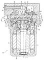
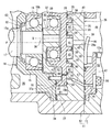
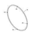
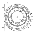
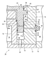
図1は、第1の実施形態に係る圧縮機の縦断面図であり、図2は圧縮機の要部を拡大して示す拡大縦断面図であり、図3は環状シール部材を示す斜視図であり、図4は図1におけるA−A線の矢視図である。
(First embodiment)
Hereinafter, a horizontal scroll compressor according to a first embodiment of the present invention will be described.
The horizontal scroll compressor (hereinafter simply referred to as “compressor”) of this embodiment is a compressor that constitutes a part of a refrigeration circuit of an in-vehicle air conditioner.
Carbon dioxide is used as a refrigerant as a compressive fluid used in the refrigeration circuit.
1 is a longitudinal sectional view of a compressor according to a first embodiment, FIG. 2 is an enlarged longitudinal sectional view showing an essential part of the compressor, and FIG. 3 is a perspective view showing an annular seal member. FIG. 4 is a view taken along line AA in FIG.
図1に示すように、第1の実施形態の圧縮機10のハウジング11は、第1ハウジング体12と第2ハウジング体13を接合して固定することにより形成されている。
第1ハウジング体12は、有底筒状の形態を呈しており、第1ハウジング体12の底部12aは図1における左側に配置されている。
第2ハウジング体13は、隔壁13aにより区画された複数の空間部を有する蓋状体であり、第1ハウジング体12における開口側の端部を覆っている。
As shown in FIG. 1, the
The
The
第1ハウジング体12における底部12aの内壁中央部には、環状の軸受用リブ12bが開口側へ向けて形成されている。
第1ハウジング体12の開口側の端部付近には、軸支部材14が収容固定されている。
軸支部材14は、挿通孔15a及び軸受収容部15bを有する円筒部15と、円筒部15の第1ハウジング体12の開口側から拡径して形成されたフランジ部16を有する。
フランジ部16の外周部は、第1ハウジング体12の内周壁と密接嵌合されている。
このため、第1ハウジング体12内の空間部は、軸支部材14により底部12a側の空間部と開口側の空間部に2分割されている。
An
Near the end of the
The
The outer peripheral portion of the
For this reason, the space part in the
第1ハウジング体12の内部には、回転軸17が収容されている。
回転軸17の一方の軸端は、軸受用リブ12b内に装着される軸受18により回転自在に支持され、他方の端部付近は、軸支部材14の軸受収容部に収容される別の軸受19により回転自在に支持されている。
第1ハウジング体12の底部12a側の空間部はモータ室20を構成し、モータ室20の内周壁に沿ってステータ21が固定されている。
モータ室20における回転軸17には、ステータ21内に収容されるロータ22が固定されている。
このように、ステータ21及びロータ22により圧縮機10における電動モータが構成され、ステータ21への電力供給により、ステータ21と回転軸17の一体的な回転を実現している。
A rotating
One shaft end of the
The space on the bottom 12 a side of the
A
As described above, the
ところで、第1ハウジング体12における開口側の空間部には、固定スクロール体25が収容され、固定スクロール体25は軸支部材14よりも第1ハウジング体12における開口端側に位置するように、第1ハウジング体12に固定されている。
そして、固定スクロール体25と軸支部材14の間には、回転軸17の回転により旋回する可動スクロール体35が配置される。
固定スクロール体25について説明すると、固定スクロール体25は、円盤状の固定基板26と、固定基板26の正面において外周縁付近に立設された外周壁27と、外周壁27の内径側において固定基板26に立設した固定渦巻壁28から構成されている。
この発明では、固定基板26において、可動スクロール体35を臨む面を固定基板26若しくは固定スクロール体25の正面としている。
従って、図1に示すように、外周壁27及び固定渦巻壁28は固定基板26の正面に立設されている。
固定渦巻壁28の先端には、シール部材29が装着されている。
外周壁27の先端は、軸支部材14におけるフランジ部16の外周付近と接合されている。
By the way, the
Between the
The
In the present invention, the surface of the fixed
Therefore, as shown in FIG. 1, the outer
A
The distal end of the outer
ところで、回転軸17の開口側の端部には、回転軸17の軸芯Pに対して偏芯する軸芯Qを持つ偏芯軸30が設けられている。
偏芯軸30には円筒状のブシュ31が嵌挿され、ブシュ31の外周には偏芯用軸受32の内輪が装着されている。
偏芯用軸受32の外輪には可動スクロール体35が支持されている。
ブシュ31にはバランサ33が設けられており、バランサ33は、軸芯周りにおける可動スクロール体35の偏在による回転軸17の偏りを緩和するための部材である。
Meanwhile, an
A cylindrical bush 31 is fitted on the
A
The bush 31 is provided with a
可動スクロール体35は、円盤状の可動基板36と、可動基板36の背面外周縁付近に立設された外周壁37と、可動基板36の正面において外周壁37の内径側に立設した可動渦巻壁38と、偏芯用軸受32の外輪を収容する軸受収容部39とを有する。
この発明では、固定スクロール体25を臨む可動基板36の一方の面を可動基板36若しくは可動スクロール体35の正面としている。
従って、図1に示すように、可動渦巻壁38は可動基板35の正面に立設されている。
可動渦巻壁38の先端には、シール部材40が装着されている。
この実施形態では、可動基板36の背面の最外周から立設される環状の外周壁37が設けられており、外周壁37の先端は軸支部材14のフランジ部16と摺動自在に当接する。
従って、軸支部材14は、可動スクロール体35に対する背面側摺接体に相当する。
可動スクロール体35における外周壁37の先端部には環状シール部材34が装着されている。
環状シール部材34については後に詳しく説明する。
The
In the present invention, one surface of the
Therefore, as shown in FIG. 1, the
A
In this embodiment, an annular outer
Accordingly, the
An
The
可動スクロール体35における可動渦巻壁38と固定スクロール体25における固定渦巻壁28は互いに噛合されている。
そして、可動渦巻壁38の先端は固定基板26に対して当接し、固定基板26に対して摺動自在である。
他方、固定渦巻壁28の先端は可動基板36に対して同様に摺動自在に当接している。
このため、固定スクロール体25と可動スクロール体35との間には、固定基板26、可動基板36、固定渦巻壁28及び可動渦巻壁38により圧縮室41が区画されている。
可動基板36の背面と、軸支部材14のフランジ部16との間には、可動スクロール体35の自転回避手段としてのピン42が複数設けられている。
The
The tip of the
On the other hand, the tip of the fixed
Therefore, a
A plurality of
固定スクロール体25の外周壁27と、可動スクロール体35の外周壁37と、軸支部材におけるフランジ部16により、吸入圧領域である吸入室43が区画されている。
軸支部材14のフランジ部16には、吸入室43とモータ室20を連通する吸入通路44が設けられている。
第1ハウジング体12には、モータ室20と連通する吸入口45が形成されており、吸入口45は外部冷媒回路の低圧側と接続されている。
このため、圧縮機10が運転されると、低圧の冷媒は、吸入口45、モータ室20、吸入通路44を通じて吸入室43へ導入される。
従って、この実施形態では、モータ室20及び吸入室43は吸入圧領域に相当する。
A
A
The
Therefore, when the
Therefore, in this embodiment, the
一方、前記ハウジング11における第2ハウジング体13には、吐出室48と、油分離室49、油回収室50が区画されている。
固定スクロール体25における中心部には吐出孔26aが形成され、吐出室48を臨む吐出孔26aの出口側にはリード式の逆止弁46が設けられている。
この実施形態では、第2ハウジング体13と固定スクロール体25の間に区画部材47が介在されており、区画部材47は、第2ハウジング体13の隔壁13aとともに、吐出室48と油回収室50を区画する手段を構成している。
吐出室48と油分離室49は隔壁13aにより区画され、油分離室49と油回収室50も隔壁13aにより区画されている。
隔壁13aは吐出室48と油分離室49を連通する通路51と、油分離室49と油回収室50を連通する通路52を有する。
On the other hand, a
A
In this embodiment, a
The
The
油分離室49には、オイルセパレータ53が備えられており、吐出圧の冷媒に含まれる潤滑油を回収することができるように図られている。
オイルセパレータ53は外部冷媒回路の高圧側と接続されている。
オイルセパレータ53により分離された潤滑油は、通路52を通じて油分離室49の潤滑油を油回収室50へ供給することができるものとなっている。
このため、圧縮機10が運転されると、圧縮された高圧の冷媒は、吐出孔26a、吐出室48、油分離室49、オイルセパレータ53を通じて外部冷媒回路へ導出される。
なお、吐出室48と、油分離室49と、油回収室50は吐出圧領域に相当する。
The
The
The lubricating oil separated by the
For this reason, when the
The
次に、可動スクロール体35に作用させる背圧の調整について説明する。
区画部材47は、油回収室50から固定基板26の背面における外周付近まで貫通する区画側通孔55を有している。
通孔55の油回収室50側はフィルタ56で覆われており、油回収室50から通孔55へ流れる潤滑油中の異物を分離するためのものである。
一方、固定スクロール体25の外周付近には、区画側通孔55と接続される固定側通孔57が形成され、固定側通孔57は固定基板26の背面から正面へ貫通している。
固定基板26の正面における外周付近(外周壁27の内径側)には、正面固定壁26bが形成され、固定側通孔57は正面固定壁26bに達している。
Next, adjustment of the back pressure applied to the
The
The
On the other hand, a fixed side through
A front fixed
固定側通孔57の正面固定壁26bにおける開口は、可動スクロール体35における可動基板36の正面外周付近を臨んでいる。
可動基板36の正面外周付近は、固定基板26の正面の外周付近である正面固定壁26bと摺接している。
可動基板36と固定基板26における正面固定壁26bとの間には微小な隙間(クリアランス)が設定されている。
この隙間は、旋回する可動スクロール体35の軸芯P方向の僅かな移動を実現する隙間を構成している。
図2に示すように、固定基板26における固定側通孔57の開口と吸入室43とを遮断するチップシール58と、固定側通孔57の開口と圧縮室41を遮断する別のチップシール59が設けられている。
The opening in the front fixed
The vicinity of the front periphery of the
A minute gap (clearance) is set between the
This gap constitutes a gap that realizes a slight movement of the orbiting
As shown in FIG. 2, a
正面固定壁26bに対向する可動基板36の正面の外周付近には、隙間(クリアランス)から可動基板36の背面に貫通する可動側通孔60が形成されている。
可動基板36の背面を臨む可動側通孔60の開口は外周壁37の内側に位置する。
可動基板36の外周壁37の内側の空間部は、可動基板36の背面と軸支部材14の内壁面により区画される背圧領域としての背圧室61を構成する。
背圧室61とモータ室20を隔絶する軸シール部材62が、軸支部材14の内壁面に装着された止め輪63により保持されている。
Near the outer periphery of the front surface of the
The opening of the movable side through
The space inside the outer
A
このように、この実施形態の圧縮機では、油回収室50から背圧室61へ連通する導入通路が形成されている。
導入通路は、吐出圧を利用した背圧調整のための通路であり、区画側通孔55、固定側通孔57と、固定基板26における正面固定壁26bと可動基板36との間の微小な隙間(クリアランス)と、可動側通孔60とから構成されている。
Thus, in the compressor of this embodiment, an introduction passage communicating from the
The introduction passage is a passage for adjusting the back pressure using the discharge pressure, and is a minute space between the partition side through
ところで、可動スクロール体35における外周壁37の先端は軸支部材14におけるフランジ部16と摺接し、外周壁37の先端に環状の環状シール部材34が装着されている点について既に言及した。
環状シール部材34は、外周壁37の先端面に刻設された装着溝37aに装着される。
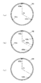
この実施形態の環状シール部材34は、弾性を有するゴム系材料により形成されており、図3に示すように、環状シール部材34の円周において等間隔(環状シール部材34の円周長を1/4に分割する間隔)に設けられた4個の溝部34a、34b、34c、34dを有する。
因みに、この溝部が設定される条件は、溝部の数が2以上であって、互いに最も離れた溝部(図3において、例えば溝部34aに対して最も離れた溝部は34cであり、34bに対して最も離れた溝部は34dである)について、環状シール部材34の円周上における溝部間の最短周上距離が環状シール部材34の円周長の3分の1以上に設定され、かつ、最長周上距離が環状シール部材34の円周長の3分の2以内に設定されていればよい。
溝部34a、34b、34c、34dは、径方向に横断する細溝であり、これらの細溝は背圧室61と吸入室43を連通する。
溝部34a、34b、34c、34dの深さは、固定基板26の正面固定壁26bと可動基板36との間に設定される隙間に対応した深さに設定されている。
溝部34a、34b、34c、34dの溝幅は、背圧室61と吸入室43との関係において絞りの機能を保つように設定されている。
By the way, it has already been mentioned that the tip of the outer
The
The
Incidentally, the condition for setting this groove portion is that the number of groove portions is two or more and the groove portions furthest away from each other (in FIG. 3, for example, the groove portion furthest away from the
The
The depth of the
The groove widths of the
このように構成されたシール部材34は、可動スクロール体35に装着された状態では、溝部34a〜34dのいずれかが背圧室61及び吸入室43における上部と下部を臨む状態となる。
つまり、背圧室61と吸入室43の上部付近を連通する細溝と、両室の下部付近を連通する細溝が存在する。
背圧室61及び吸入室43の雰囲気が一様でない場合でも、例えば、図3に示す場合では、上部と下部に位置する溝部34a、34cが存在することにより、液詰りを生じることが殆どない上部の溝部34aと、中間部に存在する溝部34b、34dを介して背圧を調整し、背圧室61において意図する背圧が設定されないおそれを低減する。
また、環状シール部材34を装着する可動スクロール体35が軸支部材14と摺接しつつ旋回するが、環状シール部材34において等間隔に4個の溝部34a〜34dを設けたことにより、環状シール部材34が装着溝37aに沿って移動しても、背圧室61と吸入室43の上部付近を連通する溝部34a〜34dの少なくとも一つと、両室の下部付近を連通する溝部34a〜34dの少なくとも一つが存在する。
When the
That is, there are a narrow groove that communicates between the
Even when the atmospheres of the
In addition, the
なお、この実施形態における背圧室61及び吸入室43の上部とは、図4に示すように、横置きされた圧縮機10の高さ方向において圧縮機10の頂部から下方へ向けて約4分の1の領域を指し、下部とは圧縮機10の底部から上方へ向けて約4分の1の領域を指している。
背圧室61及び吸入室43の上部は、冷媒がガス状態にあり、環状シール部材34の溝部34a〜34dが液詰り等を生じ難い領域である。
背圧室61及び吸入室43の下部は、冷媒がミストや液として存在する可能性が高いほか、潤滑油が溜まりやすく、環状シール部材34の溝部34a〜34dが液詰り等を起しやすい領域である。
In addition, as shown in FIG. 4, the upper part of the
The upper portions of the
In the lower part of the
次に、この圧縮機10の作用について説明する。
圧縮機10における電動モータに電力が供給されるとロータ22と回転軸17が一体的に回転される。
回転軸17の回転に伴い、可動スクロール体35が自転を回避しつつ旋回し、圧縮室41への冷媒の吸入と圧縮を行う。
吸入行程では、低圧の冷媒は、外部冷媒回路から吸入口45、モータ室20、吸入通路44を通じて吸入室43へ導入される。
圧縮行程では、圧縮室41内の容積が減少されることにより冷媒が圧縮され、圧縮された高圧の冷媒は逆止弁46を開き、吐出孔26a、吐出室48、油分離室49、オイルセパレータ53を通じて外部冷媒回路へ導出される。
オイルセパレータ53では冷媒中の潤滑油が分離され油回収室50へ回収される。
Next, the operation of the
When electric power is supplied to the electric motor in the
With the rotation of the
In the suction stroke, the low-pressure refrigerant is introduced from the external refrigerant circuit into the
In the compression stroke, the refrigerant is compressed by reducing the volume in the
In the
油回収室50は吐出圧領域の一部であり、油回収室50の冷媒は導入通路を通じて背圧室61へ導入される。
背圧室61の冷媒は、環状シール部材34の溝部を通じて吸入室43へ導出される。
背圧室61の圧力は、導入通路を通じた油回収室50からの冷媒の導入量と、環状シール部材34の溝部34a〜34dを通じた冷媒の導出量のバランスにより決定される。
The
The refrigerant in the
The pressure in the
可動スクロール体35は、背圧室61の背圧に応じて、固定スクロール体25へ押し付けられるスラスト方向の付勢力を受けるほか、圧縮室41内の冷媒圧力に応じて、軸支部材14へ押し付けられるスラスト方向の付勢力を受ける。
背圧による付勢力(背圧力)と、冷媒圧力による付勢力(圧縮力)は互いに逆方向の向きに作用する力である。
このため、背圧力と正圧力のバランスに応じて、固定スクロール体25に対する可動スクロール体35の軸芯方向の相対位置が決定される。
The
The urging force (back pressure) due to the back pressure and the urging force (compression force) due to the refrigerant pressure are forces acting in opposite directions.
For this reason, the relative position in the axial direction of the
例えば、圧縮室41内の圧力が低下し、圧縮力が背圧力を下回ると、可動スクロール体35は背圧力により、可動基板36が軸支部材14から離れる向きに変位される。
可動スクロール体35が軸支部材14から離れると、固定基板26における正面固定壁26bと可動基板36との隙間が最小(隙間無し)となる。
図5(a)に示すように、正面固定壁26bと可動基板36との隙間が最小となると、導入通路の一部を構成する隙間において吐出圧の冷媒の通過が妨げられる。
これにより、背圧室61に対して吐出圧の冷媒が導入されなくなる。
可動基板36が軸支部材14から離れる方向へ変位されることにより、逆に、可動基板36の外周壁37と軸支部材14との間には隙間が得られる。
この隙間は、可動基板36の変位前の固定基板26と可動基板36との隙間が最小となることにより生じる隙間である。
For example, when the pressure in the
When the
As shown in FIG. 5A, when the gap between the front fixed
Thereby, the refrigerant having the discharge pressure is not introduced into the
On the contrary, a gap is obtained between the outer
This gap is a gap generated by minimizing the gap between the fixed
可動基板36の外周壁37と軸支部材14との間には、環状シール部材34が設けられているから、隙間が生じても溝部34a〜34dのみ背圧室61と吸入室43を連通する状態となる。
背圧室61よりも吸入室43の圧力が低いことから、背圧室61の冷媒が溝部34a〜34dによる絞りを受けながら吸入室43へ逃がされる。
このため、背圧が低下して可動スクロール体35を固定スクロール体25へ押して付ける背圧力も下降する。
このとき、背圧室61及び吸入室43の上部と下部の雰囲気が一様でない場合、例えば、上部の雰囲気がガスで下部の雰囲気が液であることがある。
この場合、下部に位置する溝部34a〜34dのいずれかが冷媒液が詰るなどして絞りとしての機能を果たさなくても、上部に位置する溝部34a〜34dのいずれかが絞り機能を果たしつつ背圧室61の圧力を調整する。
Since the
Since the pressure in the
For this reason, a back pressure falls and the back pressure which pushes the
At this time, when the atmospheres of the upper and lower portions of the
In this case, even if any of the
一方、圧縮室41の圧力が上昇し、圧縮力が背圧力を上回ると、可動スクロール体35は、圧縮力の作用により可動基板36を固定基板26から離す方向へ変位される。
その結果、図5(b)に示すように、可動基板36の外周壁37と軸支部材14が隙間無く当接され、可動基板36の外周壁37と軸支部材14との間を冷媒が通ることができなくなる。
On the other hand, when the pressure in the
As a result, as shown in FIG. 5B, the outer
他方、可動スクロール体35における正面と固定スクロール体25における正面固定壁26bとの間には隙間が生じる。
両スクロール体25、35の正面間において、隙間が生じるときにチップシール58、59により区画された空間は導入通路の一部であり、吐出圧の冷媒が導入通路を通じて背圧室61へ導入される。
これにより、背圧室61の圧力が上昇して可動スクロール体35を固定スクロール体25へ押し付ける背圧力が上昇する。
背圧力の上昇により、可動基板36の外周壁37と軸支部材14との当接圧が軽減され、可動基板36の背面側における摩擦力が低減される。
摩擦力の軽減により動力損失が軽減でき、動力損失の軽減は圧縮機10の性能の向上に寄与する。
On the other hand, a gap is generated between the front surface of the
The space defined by the tip seals 58 and 59 when a gap is generated between the front surfaces of the
As a result, the pressure in the
As the back pressure increases, the contact pressure between the outer
The power loss can be reduced by reducing the frictional force, and the reduction of the power loss contributes to the improvement of the performance of the
また、背圧力が上昇することにより、固定スクロール体25に対する可動スクロール体35の密着度が向上する。
可動スクロール体35と固定スクロール体25との密着度が向上することにより、圧縮室41からの冷媒漏れを防止する。
冷媒漏れの防止は圧縮効率を向上させ、圧縮効率の向上は圧縮機10の性能の向上に寄与する。
Further, the increase in the back pressure improves the degree of adhesion of the
By improving the degree of adhesion between the
Prevention of refrigerant leakage improves the compression efficiency, and the improvement of the compression efficiency contributes to the improvement of the performance of the
このように、可動スクロール体35は、背圧室61の圧力に基づく背圧力が、圧縮室41内の圧力に基づく圧縮力に応じた好適な大きさとなるように、可動基板36の正面と軸支部材14との間の隙間を変化させて、背圧室61内の圧力を制御する。
背圧室61内の圧力が制御されることにより可動スクロール体35の旋回運動に伴う摺動抵抗の低減と、圧縮室41の密閉度の向上による圧縮効率の向上を図ることができる。
As described above, the
By controlling the pressure in the
この実施形態に係る圧縮機10によれば以下の効果を奏する。
(1)環状シール部材34が背圧室61と吸入室43を遮断する一方、環状シール部材に設けられた複数の溝部34a〜34dにより背圧室61と吸入室43とを連通される。溝部34a〜34dは絞り機能を有し、背圧領域よりも低圧の吸入室へ背圧室の媒体を流すことで、背圧室61の背圧を吐出圧に応じて調整する。環状シール部材34に複数の溝部34a〜34dが設けられることで、背圧室61や吸入室43の雰囲気が一様ではない場合であっても、溝部34a〜34dのいずれかが絞りとして適切に機能する。例えば、背圧室61及び吸入室43の雰囲気が下部で液、上部でガスの場合、下部に対応する溝部34a〜34dのいずれかが液等により詰った状態でもガスに対応する上部の溝部34a〜34dのいずれかの絞りにより背圧室61の背圧が適切に制御される。
The
(1) While the
(2)吐出圧領域にはオイルセパレータ53により分離された潤滑油が貯留されるため、背圧室61及び吸入室43の雰囲気はより一様となり難い条件となるが、背圧室61において意図する背圧が設定されないことを低減する効果がより顕著となる。
(3)環状シール部材34を用いるだけで、背圧室61の背圧の制御を行うことができるという簡便性が存在する。また、環状シール部材34は溝部34a〜34dを設けるだけでよく、環状シール部材34の構造も簡単で製作しやすい。
(2) Since the lubricating oil separated by the
(3) There is a convenience that the back pressure of the
(第2の実施形態)
次に、第2の実施形態に係る圧縮機について図6に基づき説明する。
この実施形態の圧縮機は第1の実施形態と同様の横置き型スクロール圧縮機である。
この実施形態の圧縮機は、可動スクロール体と軸支部材との間にのみ、背圧室が設定される圧縮機である。
図6は第2の実施形態に係る圧縮機の要部を示す拡大縦断面図である。
(Second Embodiment)
Next, a compressor according to a second embodiment will be described with reference to FIG.
The compressor of this embodiment is a horizontal scroll compressor similar to the first embodiment.
The compressor of this embodiment is a compressor in which a back pressure chamber is set only between the movable scroll body and the shaft support member.
FIG. 6 is an enlarged longitudinal sectional view showing a main part of the compressor according to the second embodiment.
この実施形態の圧縮機70の基本構造は、第1の実施形態と同様であることから、圧縮機70において共通する構成の説明は第1の実施形態の説明を援用する。
図6に示すように、有底筒状の第1ハウジング体72は、蓋状の第2ハウジング体73と接合されている。
第1ハウジング体72内の空間部は軸支部材74により区画され、第1ハウジング体72の底部側の空間部はモータ室75となっている。
Since the basic structure of the
As shown in FIG. 6, the bottomed cylindrical
A space portion in the
第1ハウジング体72の開口側の端部付近には固定スクロール体76が収容固定されており、固定スクロール体76は、固定基板77と、固定基板77の正面に立設された固定渦巻壁78と、固定基板77の正面の最外周付近に立設された外周壁79を有する。
固定基板77の背面側である第2ハウジング体73内の空間部は、吐出圧領域としての吐出室80が形成されている。
固定スクロール体76と軸支部材74の間には、可動スクロール体81が配置されている。
因みに軸支部材74は可動スクロール体81に対する背面側摺接体に相当する。
A
A
A
Incidentally, the
可動スクロール体81は、回転軸(図示せず)の偏芯軸(図示せず)に旋回自在に支持されている。
可動スクロール体81は、可動基板82と、可動基板82の正面に立設された可動渦巻壁83を有する。
可動スクロール体81と固定スクロール体76の噛合により圧縮室85が形成されている。
固定基板77における外周壁79と可動基板82の外周面の間には吸入圧領域としての吸入室86が形成されている。
吸入室86は、外周壁79及び第1ハウジング体72をともに貫通する吸入口96を通じて外部冷媒回路に接続されている。
The
The
A
A
The
可動渦巻壁83の先端が固定基板77の正面と摺接し、その先端にはチップシール87が装着され、固定渦巻壁78の先端も同様に可動基板82の正面と摺接し、先端はチップシール88が装着されている。
The tip of the
可動基板82の正面において、圧縮室85の径方向の外側である外周付近は、固定基板77の正面における正面壁77aと摺接する。
固定基板77の正面壁77aには凹部77bが形成されており、凹部77bの内径側と外側の正面壁77aには2個のチップシール89が装着されている。
In the front surface of the
A
可動基板82の背面において、吸入室86の径方向の内側である外周付近は、軸支部材74と摺接する。
軸支部材74と摺接する可動基板82の背面には環状の凹部82aが形成されており、凹部82aは背圧室を構成している。
凹部82aによる背圧室の内径側と外径側は、可動基板82の背面と軸支部材74が夫々摺接するが、可動基板82における凹部82aの外径側には外径側環状シール部材90が装着されている。
On the back surface of the
An
The inner diameter side and the outer diameter side of the back pressure chamber formed by the
外径側環状シール部材90は、背圧室である凹部82aと吸入室86を連通する細溝からなる複数の溝部90a(説明の便宜上、この実施形態では個々の溝部を区別しない。)を有する。
また、軸支部材74において凹部82aに対応する内径側には内径側環状シール部材91が装着されている。
内径側環状シール部材91は、外径側環状シール部材90に対する第2の環状シール部材に相当し、細溝からなる複数の溝部91a(説明の便宜上、この実施形態では個々の溝部を区別しない。)を有し、内径側環状シール部材91は第2溝部としての溝部91aにより、凹部82aとモータ室75との連通を可能としている。
両環状シール部材90、91は、径の大小の差が存在するほかは第1の実施形態の環状シール部材34と同じ構成である。
The outer diameter side
Further, an inner diameter side
The inner diameter side
Both
ところで、固定基板77は、吐出室80と凹部77bを連通する固定側通孔92を有する。
固定側通孔92の吐出室80側の開口はフィルタ94により覆われている。
可動スクロール体81における可動基板82は、固定基板77の凹部77b、可動基板82の凹部82aと連通する可動側通孔95を有する。
つまり、吐出室80から凹部82aを連通する冷媒の導入通路が形成されており、換言すれば、導入通路は、固定基板77の固定側通孔92及び凹部77bと、可動基板82の可動側通孔95により構成される。
By the way, the fixed
The opening on the
The
In other words, a refrigerant introduction passage that communicates from the
この実施形態の圧縮機70が運転されると、可動スクロール体81が自転を回避しつつ旋回し、圧縮室85への冷媒の吸入と圧縮を行う。
可動スクロール体81は、背圧室の背圧に応じて、固定スクロール体76へ押し付けられるスラスト方向の付勢力(背圧力)を受けるほか、圧縮室85内の冷媒圧力に応じて、軸支部材74へ押し付けられるスラスト方向の付勢力(圧縮力)を受ける。
When the
The
例えば、圧縮室85内の圧力が低下し、圧縮力が背圧力を下回ると、可動スクロール体81は背圧力により、可動基板82が軸支部材74から離れる向きに変位される。
可動スクロール体81が軸支部材74から離れると、固定基板77と可動基板82との隙間が最小(隙間無し)となる。
固定基板77と可動基板82との隙間が最小となると、導入通路における吐出圧の冷媒の通過を妨げられ、背圧室である凹部82aに対して吐出圧の冷媒が導入されなくなる。
一方、可動基板82と軸支部材74との間には、可動基板82の変位前の固定基板77と可動基板82との隙間に相当する隙間が得られることになる。
For example, when the pressure in the
When the
When the gap between the fixed
On the other hand, a gap corresponding to the gap between the fixed
可動基板82と軸支部材74との間の凹部82aの外径側には外径側環状シール部材90が設けられているから、隙間が生じても細溝90aのみが凹部82aと吸入室86を連通する状態となる。
また、内径側においては、内径側環状シール部材91の溝部91aがモータ室75と連通する空間部と凹部82aを連通する。
凹部82aよりも吸入室86及びモータ室75の圧力が低いことから、溝部90a、91aを通じて凹部82aの冷媒が絞りを受けながら逃がされ、背圧が低下して可動スクロール体81を固定スクロール体76へ押して付ける背圧力も下降する。
このとき、凹部82aの上部の雰囲気がガスであって下部の雰囲気が液である場合、各環状シール部材90、91における下部に位置する溝部90a、91aが液により詰るなど、絞りとしての機能を果たさなくても、上部に位置する溝部90a、91aが絞り機能を果たしつつ背圧室の圧力を調整する。
Since the outer diameter side
On the inner diameter side, the
Since the pressure in the
At this time, when the atmosphere in the upper portion of the
一方、圧縮室85の圧力が上昇し、正圧力が背圧力を上回ると、可動スクロール体81は正圧力により、可動基板82を固定基板77から離す方向へ変位される。
その結果、可動基板82と軸支部材74が隙間無く当接され、可動基板82の外周壁と軸支部材74との間を冷媒が通ることができなくなる。
他方、可動スクロール体81における正面と固定スクロール体76における正面との間には隙間が生じる。
両スクロール体76、81の正面の間の凹部77bにおいて、チップシール89により区画された隙間は導入通路の一部であり、吐出圧の冷媒が導入通路を通じて凹部82aへ導入される。
これにより、凹部82aの圧力が上昇して可動スクロール体76を固定スクロール体81へ押し付ける背圧力が上昇する。
On the other hand, when the pressure in the
As a result, the
On the other hand, a gap is generated between the front surface of the
In the
Thereby, the pressure of the recessed
凹部82aの上昇により、可動基板82の外周壁と軸支部材74との当接圧が軽減され、可動基板82の背面側における摩擦力が低減される。
また、背圧力が上昇することにより、固定スクロール体76に対する可動スクロール体81の密着度が向上し、圧縮室85からの冷媒漏れを防止する。
As the
Further, the back pressure increases, so that the degree of adhesion of the
この実施形態の圧縮機によれば、第1の実施形態の圧縮機が奏する作用効果(1)を奏する。
さらに言うと、この場合、外径環状シール部材90と内径環状シール部材91による背圧領域としての凹部82aが形成され、それぞれのシール部材90、91に溝部90a、91aが設けられるから、背圧領域において意図する背圧が設定されないおそれをより確実に低減することができる。
According to the compressor of this embodiment, there exists an operation effect (1) which a compressor of a 1st embodiment has.
Furthermore, in this case, the
(環状シール部材の別例)
次に、環状シール部材の別例について説明する。
第1の実施形態では、環状シール部材34の溝部である細溝をシール部材40の円周上において等間隔となるように4個の溝部34a、34b、34c、34dを設けた。
図7(a)に示す環状シール部材101は、細溝である溝部101a、101b、101cを設けた例である。
3個の溝部101a〜101cは互いに環状シール部材101の円周上において等間隔となるように配置されている。
隣合う溝部101a〜101cとの円周上の距離は、環状シール部材101の円周長の3分の1となっている。
この3個の溝部101a〜101cの配置によれば、例えば、1個の溝部101aが背圧室及び吸入室の上部を臨む場合、残りの2個の溝部101b、101cが両室の下部を臨むことになる。
この場合、背圧室及び吸入室の上部に溝部101aが、下部に溝部101b、101cが存在することにより、背圧室及び吸入室の雰囲気が一様でないことによる背圧制御の悪影響を低減することができる。
(Another example of annular seal member)
Next, another example of the annular seal member will be described.
In the first embodiment, the four
An
The three
The circumferential distance between the
According to the arrangement of the three
In this case, the presence of the
図7(b)は、溝部としての5個の溝部102a、102b、102c、102d、102eが設けられた環状シール部材102の例であるが、特に各溝部102a〜102e間の距離は等間隔ではない。
しかしながら、例えば、任意の溝部102aから最も離れた溝部102dに対する円周上の最短距離が、環状シール部材102の円周長の3分の1以上に設定され、この溝部102a、102d間の最長距離となる周上に別の溝部102eが配置されている。
このため、この例の溝部102a〜102eの配置によれば、背圧室及び吸入室の上部と下部に溝部102a〜102eいずれかが存在することになる。
FIG. 7B is an example of the
However, for example, the shortest circumferential distance with respect to the
For this reason, according to arrangement | positioning of the
図7(c)は、溝部としての2個の溝部103a、103bが設けられた環状シール部材103の例であるが、周上における溝部103a、103b間の最短距離と、最長距離はいずれも円周長の3分の1以上に設定されている。
このため一方の溝部103aが背圧室及び吸入室の下部を臨む場合、他方の溝部103bは上部に位置することになる。
なお、両溝部103a、103bがほぼ同じ高さ、すなわち、圧縮機の中心付近の高さに位置する場合が考えられる。
しかし、少なくとも、下部に細溝103a、103bが存在しないことから、液やミストが細溝103aに詰る可能性は殆どなく、背圧室及び吸入室の雰囲気が一様でないことによる背圧制御の悪影響を受ける可能性は極めて少ない。
FIG. 7C shows an example of the
For this reason, when one
In addition, the case where both the
However, since at least the
図7(a)〜図7(c)に示すように、環状シール部材101〜103における溝部である溝部101a〜101c、102a〜102e、103a、103bは、複数個であって、任意の溝部から最も離れた溝部との周上における最短距離と、最長距離がいずれも円周長の3分の1以上に設定されていればよい。
さらに、好ましくは、溝部を3個以上設けるようにして、任意の溝部から最も離れた溝部との周上における最短距離を円周長の3分の1以上とするとともに、この溝部間の最長距離が設定される円周上に別の溝部を設けるようにすればよい。
As shown in FIGS. 7A to 7C, the
Further, preferably, three or more groove portions are provided so that the shortest distance on the circumference with the groove portion furthest away from any groove portion is at least one third of the circumferential length, and the longest distance between the groove portions. What is necessary is just to make it provide another groove part on the circumference where is set.
(溝部の別例)
次に、環状シール部材の溝部の別例について説明する。
第1の実施形態では、環状シール部材34において単一の細溝が溝部34a〜34dを実質的に構成するとした。
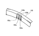
図8に示す溝部は径方向に刻設された3本の細溝105aが互いに平行に配置された環状シール部材105の例である。
細溝105a間に軸支部材と当接する溝間当接面105bが形成されることにより、細溝105a付近の剛性が維持され、溝部の変形を防止することができる。
なお、溝部の断面形態は、四角溝に限らず、円弧溝、逆三角溝等、溝として機能することができる断面であれば、特に限定されない。
(Another example of groove)
Next, another example of the groove portion of the annular seal member will be described.
In the first embodiment, the single narrow groove in the
The groove portion shown in FIG. 8 is an example of the
By forming the
In addition, the cross-sectional form of a groove part will not be specifically limited if it is a cross section which can function as a groove | channel not only a square groove | channel but arc grooves, an inverted triangular groove, etc.
本発明は、上記した第1、第2の実施形態や変形例に限定されるものではなく例えば、以下のように、発明の趣旨の範囲内で種々の変更が可能である。
○ 上記の第1、2の実施形態では、環状シール部材の4個の溝部は互いに環状シール部材の円周上において等間隔となるように配置したが、例えば、図7(a)〜図7(c)の環状シール部材を採用してもよい。
○ 第2の実施形態では内径側環状シール部材を採用したが、溝部のないチップシールを用いてもよい。この場合、吸入室と背圧室を連通する外径側シール部材の溝部により背圧を制御する。
また、内径側環状シール部材の溝部と、外径側環状シール部材の構成を互いに異なるようにしていもよく、例えば、溝部の数、溝部を構成する細溝の数を異なるようにしてもよい。
○ 第1の実施形態では、背圧室とモータ室を隔絶する軸シール部材を設け、モータ室を吸入圧領域としたが、軸シール部材を設けずにモータ室を背圧領域とするようにしてもよい。この場合、吸入口をモータ室と連通させず、吸入通路を設ける必要がある。
○ 第1の実施形態では、オイルセパレータを設けて冷媒中の潤滑油を分離して回収し、回収された潤滑油を導入通路にのみ通し、環状シール部材の溝部は潤滑油の通過させるようにしたが、導入通路とは別の潤滑油を通す通路を設けてもよい。これにより、環状シール部材の溝部における液詰りを生じにくくすることができる。
The present invention is not limited to the first and second embodiments and modifications described above, and various modifications are possible within the scope of the invention as follows, for example.
In the first and second embodiments described above, the four groove portions of the annular seal member are arranged at equal intervals on the circumference of the annular seal member. For example, FIG. 7 (a) to FIG. You may employ | adopt the cyclic | annular sealing member of (c).
In the second embodiment, the inner diameter side annular seal member is used, but a chip seal without a groove may be used. In this case, the back pressure is controlled by the groove portion of the outer diameter side sealing member that communicates the suction chamber and the back pressure chamber.
Further, the configuration of the groove portion of the inner diameter side annular seal member and the configuration of the outer diameter side annular seal member may be different from each other. For example, the number of groove portions and the number of fine grooves constituting the groove portion may be different.
○ In the first embodiment, the shaft seal member separating the back pressure chamber and the motor chamber is provided and the motor chamber is used as the suction pressure region. However, the motor chamber is used as the back pressure region without providing the shaft seal member. May be. In this case, it is necessary to provide a suction passage without connecting the suction port to the motor chamber.
In the first embodiment, an oil separator is provided to separate and collect the lubricating oil in the refrigerant, and the collected lubricating oil is passed only through the introduction passage, and the groove of the annular seal member is passed through the lubricating oil. However, you may provide the channel | path which lets lubricating oil different from an introduction channel | path. Thereby, liquid clogging in the groove portion of the annular seal member can be made difficult to occur.
10、70 横置き型スクロール圧縮機
14 軸支部材
25、76 固定スクロール体
26、77 固定基板
26b 正面固定壁
27、79 外周壁
28、78 固定渦巻壁
34、101〜103 環状シール部材
34a、34b、34c、34d、90a、91a、101a、101b、101c、102a、102b、102c、102d、102e、103a、103b 溝部
35、81 可動スクロール体
36、82 可動基板
37 外周壁
37a 装着溝
38、83 可動渦巻壁
41 圧縮室
43、86 吸入室
48、80 吐出室
50 油回収室
53 オイルセパレータ
55 区画側通孔
57 固定側通孔
60 可動側通孔
61 背圧室
82a 凹部
90 外径環状シール部材
91 内径環状シール部材
P、Q 軸芯
DESCRIPTION OF
Claims (4)
前記可動基板と前記背面側摺接体との間に前記背圧領域と前記吸入圧領域を遮断する環状シール部材が介在され、
前記環状シール部材は、前記可動スクロール体に刻設された装着溝に装着されると共に、複数の溝部を有し、
前記溝部は、前記環状シール部材の端面において径方向に形成された細溝であり、前記可動スクロール体が前記背面側摺接体から離れる方向に変位され前記可動基板と前記背面側摺接体との間に隙間が得られると前記背圧領域と前記吸入圧領域とを連通し、
互いに最も離れた前記溝部について、前記環状シール部材の円周上における該溝部間の最短周上距離が前記環状シール部材の円周長の3分の1以上に設定され、
前記導入通路は前記固定基板と前記可動基板との間に設定された微小な隙間を備え、前記可動スクロール体が前記可動基板を前記固定基板から離す方向へ変位され前記可動基板と前記固定基板との間に隙間が生じると前記背圧領域と前記吐出圧領域とを連通することを特徴とする横置き型スクロール圧縮機。 A fixed scroll body having a fixed substrate fixed in the housing and a fixed spiral wall standing upright in front of the fixed substrate, and a movable scroll in which a movable spiral wall meshing with the fixed spiral wall is set up in front of the movable substrate And a back side sliding contact body that has a compression chamber defined between the fixed spiral wall and the movable spiral wall and that is in sliding contact with the rear surface of the movable substrate, and a back pressure region is provided on the rear surface of the movable substrate. The back pressure region and the discharge pressure region are communicated with each other via an introduction passage, and a suction pressure region is defined separately from the back pressure region, and the volume of the compression chamber is reduced due to the orbiting motion of the movable scroll body and Horizontal scroll compression that compresses compressible fluid by movement and adjusts the pressure in the back pressure region by displacement of the movable scroll body in the contact / separation direction between the fixed substrate and the back side sliding contact body. In,
An annular seal member that interrupts the back pressure region and the suction pressure region is interposed between the movable substrate and the back side sliding contact body,
The annular seal member is mounted in a mounting groove carved in the movable scroll body, and has a plurality of groove portions,
The groove is a narrow groove formed in the radial direction on the end surface of the annular seal member, and the movable scroll body is displaced in a direction away from the back side sliding contact body, and the movable substrate and the back side sliding contact body are When a gap is obtained between the back pressure region and the suction pressure region,
For the groove portions that are farthest from each other, the shortest circumferential distance between the groove portions on the circumference of the annular seal member is set to one third or more of the circumferential length of the annular seal member,
The introduction passage has a minute gap set between the fixed substrate and the movable substrate, and the movable scroll body is displaced in a direction to separate the movable substrate from the fixed substrate. A horizontal scroll compressor characterized in that the back pressure region and the discharge pressure region communicate with each other when a gap is generated between them .
Priority Applications (2)
| Application Number | Priority Date | Filing Date | Title |
|---|---|---|---|
| JP2006033155A JP4635893B2 (en) | 2006-02-10 | 2006-02-10 | Horizontal scroll compressor |
| EP20070002715 EP1818541B1 (en) | 2006-02-10 | 2007-02-08 | Horizontally-mounted scroll compressor |
Applications Claiming Priority (1)
| Application Number | Priority Date | Filing Date | Title |
|---|---|---|---|
| JP2006033155A JP4635893B2 (en) | 2006-02-10 | 2006-02-10 | Horizontal scroll compressor |
Publications (2)
| Publication Number | Publication Date |
|---|---|
| JP2007211702A JP2007211702A (en) | 2007-08-23 |
| JP4635893B2 true JP4635893B2 (en) | 2011-02-23 |
Family
ID=38015303
Family Applications (1)
| Application Number | Title | Priority Date | Filing Date |
|---|---|---|---|
| JP2006033155A Expired - Fee Related JP4635893B2 (en) | 2006-02-10 | 2006-02-10 | Horizontal scroll compressor |
Country Status (2)
| Country | Link |
|---|---|
| EP (1) | EP1818541B1 (en) |
| JP (1) | JP4635893B2 (en) |
Cited By (1)
| Publication number | Priority date | Publication date | Assignee | Title |
|---|---|---|---|---|
| JPH0747441B2 (en) | 1990-01-13 | 1995-05-24 | 名古屋精工株式会社 | Cable suspension mechanism |
Families Citing this family (12)
| Publication number | Priority date | Publication date | Assignee | Title |
|---|---|---|---|---|
| JP5408073B2 (en) * | 2010-08-17 | 2014-02-05 | 株式会社豊田自動織機 | Compressor |
| KR102067141B1 (en) * | 2015-03-19 | 2020-01-17 | 한온시스템 주식회사 | Oil separation device of the compressor |
| KR102549777B1 (en) * | 2016-12-21 | 2023-06-30 | 삼성전자주식회사 | Scroll compressor |
| JP6753355B2 (en) | 2017-05-16 | 2020-09-09 | 株式会社デンソー | Scroll compressor |
| JP7052563B2 (en) * | 2018-05-28 | 2022-04-12 | 株式会社デンソー | Compressor |
| KR20200095994A (en) * | 2019-02-01 | 2020-08-11 | 엘지전자 주식회사 | Scroll compressor improved Assembly structure |
| JP7063299B2 (en) * | 2019-03-27 | 2022-05-09 | 株式会社豊田自動織機 | Scroll compressor |
| KR101999325B1 (en) * | 2019-05-27 | 2019-07-12 | 한온시스템 주식회사 | Scroll compressor |
| US12110923B2 (en) | 2019-12-17 | 2024-10-08 | Eagle Industry Co., Ltd. | Sliding component |
| JP2025098615A (en) * | 2023-12-20 | 2025-07-02 | 株式会社豊田自動織機 | Scroll-type compressor |
| DE102024111797A1 (en) * | 2024-04-26 | 2025-10-30 | OET GmbH | Scroll compressor for compressing high-pressure refrigerant |
| JP2026006897A (en) * | 2024-07-01 | 2026-01-16 | 株式会社豊田自動織機 | Scroll Compressor |
Family Cites Families (8)
| Publication number | Priority date | Publication date | Assignee | Title |
|---|---|---|---|---|
| JPH06336986A (en) * | 1993-05-28 | 1994-12-06 | Hitachi Ltd | Lubrication mechanism of scroll compressor |
| US5383772A (en) * | 1993-11-04 | 1995-01-24 | Tecumseh Products Company | Scroll compressor stabilizer ring |
| JP3344843B2 (en) * | 1994-10-24 | 2002-11-18 | 株式会社日立製作所 | Scroll compressor |
| JPH0996363A (en) * | 1995-09-29 | 1997-04-08 | Ntn Corp | Seal ring |
| JPH10159755A (en) * | 1996-11-29 | 1998-06-16 | Matsushita Electric Ind Co Ltd | Scroll compressor |
| JP2000136782A (en) * | 1998-10-30 | 2000-05-16 | Denso Corp | Scroll compressor |
| JP4007189B2 (en) * | 2002-12-20 | 2007-11-14 | 株式会社豊田自動織機 | Scroll compressor |
| JP4329528B2 (en) * | 2003-12-19 | 2009-09-09 | 株式会社豊田自動織機 | Scroll compressor |
-
2006
- 2006-02-10 JP JP2006033155A patent/JP4635893B2/en not_active Expired - Fee Related
-
2007
- 2007-02-08 EP EP20070002715 patent/EP1818541B1/en not_active Not-in-force
Cited By (1)
| Publication number | Priority date | Publication date | Assignee | Title |
|---|---|---|---|---|
| JPH0747441B2 (en) | 1990-01-13 | 1995-05-24 | 名古屋精工株式会社 | Cable suspension mechanism |
Also Published As
| Publication number | Publication date |
|---|---|
| JP2007211702A (en) | 2007-08-23 |
| EP1818541A1 (en) | 2007-08-15 |
| EP1818541B1 (en) | 2014-06-25 |
Similar Documents
| Publication | Publication Date | Title |
|---|---|---|
| EP1818541B1 (en) | Horizontally-mounted scroll compressor | |
| EP2781753B1 (en) | Scroll compressor with back pressure discharge | |
| EP2206926A2 (en) | Scroll compressor | |
| KR102549777B1 (en) | Scroll compressor | |
| KR102400430B1 (en) | Scroll compressor | |
| US8152504B2 (en) | Method of operation of a spherical positive displacement rotary machine and devices for carrying out said method | |
| CN1854525A (en) | Scroll machine | |
| JP2005180345A (en) | Scroll compressor | |
| EP1681467B1 (en) | Multi-stage rotary compressor | |
| JP2016223390A (en) | Scroll compressor | |
| US6217302B1 (en) | Floating seal bias for reverse fun protection in scroll compressor | |
| JPWO2016084874A1 (en) | Vane type compressor | |
| CN217999879U (en) | Compression mechanism and scroll compressor | |
| CN111980918B (en) | Scroll compressor having a rotor with a rotor shaft having a rotor shaft with a | |
| US9897088B2 (en) | Scroll compressor with back pressure chamber having leakage channel | |
| JP5690674B2 (en) | Scroll compressor | |
| EP2483563A2 (en) | Rotary compressor | |
| JPH0821382A (en) | Scroll compressor | |
| JP2009127440A (en) | Scroll compressor | |
| KR102949923B1 (en) | Scroll compressor | |
| JP2015105594A (en) | Scroll compressor | |
| KR20140114219A (en) | Scroll compressor with fixed scroll supporting means | |
| JP4970902B2 (en) | Scroll compressor | |
| JP6692195B2 (en) | Scroll compressor | |
| JP4698299B2 (en) | Scroll compressor |
Legal Events
| Date | Code | Title | Description |
|---|---|---|---|
| A621 | Written request for application examination |
Free format text: JAPANESE INTERMEDIATE CODE: A621 Effective date: 20080201 |
|
| A977 | Report on retrieval |
Free format text: JAPANESE INTERMEDIATE CODE: A971007 Effective date: 20100205 |
|
| A131 | Notification of reasons for refusal |
Free format text: JAPANESE INTERMEDIATE CODE: A131 Effective date: 20100209 |
|
| A521 | Request for written amendment filed |
Free format text: JAPANESE INTERMEDIATE CODE: A523 Effective date: 20100412 |
|
| A131 | Notification of reasons for refusal |
Free format text: JAPANESE INTERMEDIATE CODE: A131 Effective date: 20100608 |
|
| A521 | Request for written amendment filed |
Free format text: JAPANESE INTERMEDIATE CODE: A523 Effective date: 20100803 |
|
| TRDD | Decision of grant or rejection written | ||
| A01 | Written decision to grant a patent or to grant a registration (utility model) |
Free format text: JAPANESE INTERMEDIATE CODE: A01 Effective date: 20101026 |
|
| A01 | Written decision to grant a patent or to grant a registration (utility model) |
Free format text: JAPANESE INTERMEDIATE CODE: A01 |
|
| A61 | First payment of annual fees (during grant procedure) |
Free format text: JAPANESE INTERMEDIATE CODE: A61 Effective date: 20101108 |
|
| FPAY | Renewal fee payment (event date is renewal date of database) |
Free format text: PAYMENT UNTIL: 20131203 Year of fee payment: 3 |
|
| R151 | Written notification of patent or utility model registration |
Ref document number: 4635893 Country of ref document: JP Free format text: JAPANESE INTERMEDIATE CODE: R151 |
|
| FPAY | Renewal fee payment (event date is renewal date of database) |
Free format text: PAYMENT UNTIL: 20131203 Year of fee payment: 3 |
|
| LAPS | Cancellation because of no payment of annual fees |