JP4635808B2 - Image reading apparatus and lighting control method - Google Patents
Image reading apparatus and lighting control method Download PDFInfo
- Publication number
- JP4635808B2 JP4635808B2 JP2005284685A JP2005284685A JP4635808B2 JP 4635808 B2 JP4635808 B2 JP 4635808B2 JP 2005284685 A JP2005284685 A JP 2005284685A JP 2005284685 A JP2005284685 A JP 2005284685A JP 4635808 B2 JP4635808 B2 JP 4635808B2
- Authority
- JP
- Japan
- Prior art keywords
- lamp
- reflective
- original
- document
- transparent
- Prior art date
- Legal status (The legal status is an assumption and is not a legal conclusion. Google has not performed a legal analysis and makes no representation as to the accuracy of the status listed.)
- Expired - Fee Related
Links
Images


Landscapes
- Optical Systems Of Projection Type Copiers (AREA)
- Light Sources And Details Of Projection-Printing Devices (AREA)
- Facsimile Scanning Arrangements (AREA)
Description
本発明は、画像読み取り装置の技術に関する。 The present invention relates to a technology of an image reading apparatus.
画像読み取り装置には、反射原稿用ランプと、透過原稿用ランプとを備え、文書等の反射原稿および写真フィルム等の透過原稿を読み取るものが知られている。画像読み取り装置では、反射原稿用ランプおよび透過原稿用ランプに、点滅させても寿命が短くなりにくい冷陰極型蛍光ランプ(CCFL)が利用されることが多い。 2. Description of the Related Art An image reading apparatus is known that includes a reflective original lamp and a transparent original lamp and reads a reflective original such as a document and a transparent original such as a photographic film. In an image reading apparatus, a cold cathode fluorescent lamp (CCFL) is often used as the reflective original lamp and the transparent original lamp, even if the lamp is blinked.
ところで、CCFLは、光が遮断されている暗黒環境に長時間おかれた場合、始動から点灯までの始動時間が長くなるという問題、すなわち「暗黒始動性」が悪いという問題を有している。具体的には、CCFLは、ランプの点灯の際に放電のきっかけとなる初期電子が必要である。初期電子は、暗黒環境に放置されると減少する。そのため、CCFLは、暗黒環境に放置されると始動時間が長くなってしまう。 By the way, CCFL has a problem that when it is left in a dark environment where light is blocked for a long time, the starting time from the start to the lighting becomes long, that is, the “dark startability” is bad. Specifically, the CCFL requires initial electrons that trigger discharge when the lamp is turned on. Initial electrons decrease when left in a dark environment. For this reason, when the CCFL is left in a dark environment, the start-up time becomes long.
したがって、反射原稿用ランプや透過原稿用ランプにCCFLを用いた画像読み取り装置では、暗黒状態に放置された状態のままで電源を投入すると、CCFLが点灯せずに使用できないことがある。例えば、長時間にわたりスキャナ原稿台の蓋を閉めた状態にすると、反射原稿用ランプが設置されているキャリッジに光が受光しない。このような場合、画像読み取り装置は、反射原稿の読み取りに長時間かかってしまう。また、例えば、画像読み取り装置を梱包から取り出してから利用する場合も、反射原稿用ランプおよび透過原稿用ランプに光が当たっていなかったため原稿の読み取りに時間がかかってしまう。 Therefore, an image reading apparatus using a CCFL as a reflective document lamp or a transparent document lamp may not be used because the CCFL does not light up when the power is turned on in a dark state. For example, if the scanner document table is closed for a long time, no light is received by the carriage on which the reflective document lamp is installed. In such a case, the image reading apparatus takes a long time to read the reflection original. Further, for example, when the image reading apparatus is used after being taken out of the package, it takes time to read the original because light is not applied to the reflective original lamp and the transparent original lamp.
上記の問題を解決する方法として、補助光源を用いる方法が知られている(例えば、特許文献1)。特許文献1では、補助光源により放電ランプを照明して放電ランプの初期電子を増加させるようにしている。そのため、特許文献1では、放電ランプが暗黒環境に長時間おかれた場合であっても、放電ランプの始動時間を短縮することができる。 As a method for solving the above problem, a method using an auxiliary light source is known (for example, Patent Document 1). In Patent Document 1, the discharge lamp is illuminated by an auxiliary light source to increase the initial electrons of the discharge lamp. Therefore, in Patent Document 1, even when the discharge lamp is left in a dark environment for a long time, the starting time of the discharge lamp can be shortened.
また、上記の問題を解決する他の方法として、蛍光ランプに外光を導く導光部材を利用する方法も提案されている(例えば、特許文献2)。特許文献2では、導光部材を設けたことで、蛍光ランプが暗黒状態に置かれる可能性を低減することができる。 As another method for solving the above problem, a method using a light guide member that guides external light to a fluorescent lamp has been proposed (for example, Patent Document 2). In Patent Document 2, by providing the light guide member, the possibility that the fluorescent lamp is placed in a dark state can be reduced.
しかしながら、上記特許文献1は、以下の問題を有している。具体的には、特許文献1の方法では、ランプを点灯させるたびに補助光源を点灯するようにしている。すなわち、特許文献1では、ランプの暗黒始動性が悪くない場合(例えば、ランプが暗黒状態に置かれていない場合等)でも、補助光源を点灯させてしまう。そのため、特許文献1では、無駄なコストが生じてしまう。 However, Patent Document 1 has the following problems. Specifically, in the method of Patent Document 1, the auxiliary light source is turned on every time the lamp is turned on. That is, in Patent Document 1, the auxiliary light source is turned on even when the dark startability of the lamp is not bad (for example, when the lamp is not placed in a dark state). Therefore, in Patent Document 1, a wasteful cost occurs.
また、特許文献2の方法では、装置が暗黒環境に置かれている場合には、初期電子の減少を防止することができないという問題を有している。装置が暗黒環境の置かれている場合、そもそも、導光部材にも光が受光しないためである。 In addition, the method of Patent Document 2 has a problem that when the apparatus is placed in a dark environment, the reduction of initial electrons cannot be prevented. This is because light is not received by the light guide member in the first place when the device is placed in a dark environment.
本発明は、上記事情に鑑みてなされたものであり、本発明の目的は、暗黒始動性の悪いランプを低コストで点灯させる画像読み取り装置を提供することにある。 The present invention has been made in view of the above circumstances, and an object of the present invention is to provide an image reading apparatus that lights a lamp with poor dark startability at low cost.
上記課題を解決するため、本発明の一態様は、反射原稿用ランプの光を原稿に照射して該原稿からの反射光を電気信号に変換する画像読み取り装置に適用される。 In order to solve the above-described problem, one embodiment of the present invention is applied to an image reading device that irradiates a document with light from a reflective document lamp and converts reflected light from the document into an electrical signal.
そして、前記画像読み取り装置は、前記反射原稿用ランプと、光を検知し電気信号に変換するイメージセンサとが収納され、該原稿の副走査方向に移動するキャリッジと、前記キャリッジが所定位置にある場合に、該キャリッジに収納されている反射原稿用ランプに対して光を照射できる位置に設置されている補助光源と、前記反射原稿用ランプの点灯および消灯、前記補助光源の点灯および消灯、前記イメージセンサの動作、および前記キャリッジの位置を制御する制御部と、を有し、前記制御部は、電源が投入された際、前記キャリッジを白基準の読み取り位置に設定すると共に前記反射原稿用ランプの点灯を指示し、該指示してから所定時間経過後に前記イメージセンサが検知して変換した電気信号を取得する手段と、前記取得した電気信号が所定値に満たない場合に前記反射原稿用ランプが点灯していないと判定し、該所定値以上の場合には前記反射原稿用ランプが点灯していると判定する手段と、前記反射原稿用ランプが点灯していないと判定した場合、前記反射原稿用ランプの消灯を指示し、前記キャリッジを前記所定位置に移動させて前記補助光源を点灯させ、該補助光源の光を反射原稿用ランプに照射させる手段と、を有する。 In the image reading apparatus, the reflective document lamp and an image sensor that detects light and converts it into an electrical signal are housed, and the carriage moves in the sub-scanning direction of the document, and the carriage is in a predetermined position. In this case, the auxiliary light source installed at a position where light can be emitted to the reflective original lamp stored in the carriage, the reflective original lamp is turned on and off, the auxiliary light source is turned on and off, A control unit that controls the operation of the image sensor and the position of the carriage, and the control unit sets the carriage to a white reference reading position when the power is turned on, and the reflective document lamp. And a means for acquiring an electric signal detected and converted by the image sensor after a predetermined time has elapsed since the instruction, and the acquired electric power Means for determining that the reflective document lamp is not lit when the signal is less than a predetermined value, and determining that the reflective document lamp is lit when the signal is equal to or greater than the predetermined value; When it is determined that the lamp for lighting is not lit, the turning off of the reflecting document lamp is instructed, the carriage is moved to the predetermined position to turn on the auxiliary light source, and the light from the auxiliary light source is reflected on the reflecting document lamp. And irradiating means.
このように本発明の一態様では、反射原稿用ランプに光を照射する補助光源を設け、電源が投入された際に白基準の読み取りを行い、その読み取った値により反射原稿用ランプが点灯しているか否かを判定するようにしている。すなわち、本一態様では、反射原稿用ランプの点灯判定を、一般的な画像読み取り装置が有する白基準の読み取り機能を利用している。そのため、本一態様では、ランプの点灯判定のために新たな構成を設ける必要がない。また、反射原稿用ランプが点灯していないと判定した場合に補助光源を点灯させて反射原稿用ランプに光を照射するようにしている。したがって、本一態様によれば、画像読み取り装置の暗黒始動性の悪い反射原稿用ランプを低コストで点灯させることができるようになる。 As described above, in one aspect of the present invention, an auxiliary light source that irradiates light to the reflective original lamp is provided, and when the power is turned on, white reference reading is performed, and the reflective original lamp is turned on according to the read value. It is determined whether or not. That is, in this aspect, the lighting reference lamp is turned on using the white reference reading function of a general image reading apparatus. Therefore, in this aspect, it is not necessary to provide a new configuration for determining whether the lamp is turned on. In addition, when it is determined that the reflective original lamp is not lit, the auxiliary light source is turned on to irradiate the reflective original lamp with light. Therefore, according to this aspect, it is possible to light the low-cost reflective original lamp of the image reading apparatus with low dark startability.
また、前記画像読み取り装置であって、前記補助光源は、発光ダイオード(LED)であることとしてもよい。このように構成するのは、発光ダイオードは、暗黒始動性が悪いという性質を有さないためである。すなわち、本一態様によれば、反射原稿用ランプが点灯しない場合、補助光源の光を確実に反射原稿用ランプに照射させて、暗黒始動性の問題を解消させることができるようになる。 In the image reading apparatus, the auxiliary light source may be a light emitting diode (LED). The reason for this configuration is that the light emitting diode does not have the property of poor dark startability. That is, according to this aspect, when the reflective document lamp is not turned on, the light of the auxiliary light source can be surely irradiated to the reflective document lamp, and the problem of the dark startability can be solved.
また、前記画像読み取り装置であって、前記キャリッジは、前記白基準の読み取り位置がホームポジションに設定されていることとしてもよい。このように構成することで、画像読み取り装置は、電源が投入された際に、すぐに白基準の読み取り処理を開始することができる。そのため、本一態様によれば、画像読み取り装置の起動処理をより迅速に行うこができる。 In the image reading apparatus, the white reference reading position may be set to a home position in the carriage. With this configuration, the image reading apparatus can immediately start the white reference reading process when the power is turned on. Therefore, according to this aspect, the activation process of the image reading apparatus can be performed more quickly.
また、本発明の他の態様は、反射原稿を照明する反射原稿用ランプと、透過原稿を照明する透過原稿用ランプと、該反射原稿用ランプに照明された反射原稿および透過原稿用ランプに照明された透過原稿を読み取るイメージセンサとを備えた画像読み取り装置に適用される。 In another aspect of the present invention, a reflective original lamp for illuminating a reflective original, a transparent original lamp for illuminating a transparent original, and a reflective original and a transparent original lamp illuminated by the reflective original lamp are illuminated. The present invention is applied to an image reading apparatus including an image sensor that reads a transmitted original document.
そして、前記画像読み取り装置は、前記反射原稿用ランプおよび前記イメージセンサが収納され、該原稿の副走査方向に移動するキャリッジと、前記反射原稿用ランプの点灯および消灯、前記透過原稿用ランプの点灯および消灯、前記イメージセンサの動作、および前記キャリッジの位置を制御する制御部と、前記透過原稿用ランプに点灯が指示されると該指示にしたがい点灯し、前記透過原稿用ランプに消灯が指示されると該指示にしたがい消灯する補助光源と、を有し、前記キャリッジが所定位置にある場合、前記透過原稿用ランプから放射された光が前記反射原稿用ランプに至る光路と、前記補助光源から放射された光が前記反射原稿用ランプに至る光路とが形成されていて、前記制御部は、電源が投入された際、前記キャリッジを白基準の読み取り位置に設定して反射原稿用ランプの点灯を指示し、該指示してから所定時間経過後に前記イメージセンサが読み取った信号を取得する手段と、前記取得した信号が所定値に満たない場合に前記反射原稿用ランプが点灯していないと判定し、該所定値以上の場合には前記反射原稿用ランプが点灯していると判定する手段と、前記反射原稿用ランプが点灯していないと判定した場合、該反射原稿用ランプの消灯を指示し、前記キャリッジを前記所定位置に移動させて前記透過原稿用ランプの点灯を指示し、前記透過原稿用ランプからの光および補助光源からの光を該反射原稿用ランプに照射させる手段と、を有する。 In the image reading apparatus, the reflective original lamp and the image sensor are housed, the carriage moves in the sub-scanning direction of the original, the reflective original lamp is turned on and off, and the transparent original lamp is turned on. When the lighting of the control unit that controls the operation of the image sensor and the position of the carriage and the transparent original lamp is instructed to be turned on, the light is turned on according to the instruction, and the transparent original lamp is instructed to be turned off. An auxiliary light source that turns off in accordance with the instruction, and when the carriage is in a predetermined position, the light emitted from the transparent original lamp reaches the reflective original lamp, and the auxiliary light source An optical path is formed for the emitted light to reach the reflective original lamp, and the control unit turns the carriage white when the power is turned on. Means for setting the quasi-reading position to instruct the lighting of the reflective original lamp, and acquiring the signal read by the image sensor after a predetermined time has elapsed since the instruction, and the acquired signal is less than the predetermined value In this case, it is determined that the reflective document lamp is not lit, and if the value is equal to or greater than the predetermined value, the reflective document lamp is determined to be lit, and the reflective document lamp is not lit. If it is determined that the reflective original lamp is turned off, the carriage is moved to the predetermined position to turn on the transparent original lamp, and the light from the transparent original lamp and the auxiliary light source And means for irradiating the lamp for reflecting document with light.
このように、本発明の他の態様によれば、反射原稿用ランプに光を照射する光源として、透過原稿用ランプと、透過原稿用ランプへの指示にしたがい点灯あるいは消灯する補助光源とを利用している。また、電源が投入された際に白基準の読み取りを行い、その読み取った値により反射原稿用ランプが点灯しているか否かを判定している。そして、反射原稿用ランプが点灯していないと判定した場合に透過原稿用ランプおよび補助光源を点灯させて反射原稿用ランプに光を照射するようにしている。そのため、本発明の他の態様によれば、反射原稿用ランプおよび透過原稿用ランプを備えた画像読み取り装置において、暗黒始動性の悪い反射原稿用ランプを低コストで点灯させることができるようになる。 Thus, according to another aspect of the present invention, as a light source for irradiating light to a reflective original lamp, a transparent original lamp and an auxiliary light source that is turned on or off according to an instruction to the transparent original lamp are used. is doing. Further, when the power is turned on, the white reference is read, and it is determined whether or not the reflective original lamp is lit based on the read value. When it is determined that the reflective original lamp is not lit, the transparent original lamp and the auxiliary light source are turned on to irradiate the reflective original lamp with light. Therefore, according to another aspect of the present invention, in an image reading apparatus provided with a reflective original lamp and a transparent original lamp, a reflective original lamp with poor dark startability can be lit at low cost. .
以下、本発明の実施形態について図面を用いて説明する。 Hereinafter, embodiments of the present invention will be described with reference to the drawings.
先ず、本発明の一実施形態が適用された画像読み取り装置の概略構成について、図1および図2を用いて説明する。 First, a schematic configuration of an image reading apparatus to which an embodiment of the present invention is applied will be described with reference to FIGS. 1 and 2.
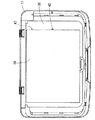
図1は、本発明の実施形態の画像読み取り装置としてのイメージスキャナの内部構造を示す模式図である。図2は、本発明の実施形態のイメージスキャナの図1とは異なる位置での断面を示す模式図である。なお、本実施形態は、プラテン10に載置された原稿1000を読み取るフラットベット型のイメージスキャナ1を例にする。原稿1000は、文書、写真、書籍等の反射原稿、或いは35mmストリップフィルム、35mmマウントフィルム、ブローニフィルム等の透過原稿である。
FIG. 1 is a schematic diagram showing an internal structure of an image scanner as an image reading apparatus according to an embodiment of the present invention. FIG. 2 is a schematic diagram illustrating a cross-section at a position different from that of FIG. 1 of the image scanner according to the embodiment of the present invention. In the present embodiment, the flat bed type image scanner 1 that reads the
イメージスキャナ1は、原稿カバー11と、原稿1000を搭載するためのプラテン10を備えたハウジング13とを有する。そして、原稿カバー11は、ヒンジ12により、プラテン10の原稿搭載面10aを開放する姿勢と原稿搭載面10aを覆う姿勢とに揺動可能な状態でハウジング13に連結されている。なお、図1および図2に示す原稿カバー11は、原稿搭載面10aを覆う姿勢を示している。
The image scanner 1 includes a
ハウジング13には、画像補正(シェーディング補正)に利用する白基準板2000が設けられている。白基準板2000が設置される位置について特に限定しないが、本実施形態では、プラテン10の一方の端部に設けられているものとする。
The
また、ハウジング13には、原稿搭載面10aに平行なガイドロッド18と、ガイドロッド18に摺動自在に嵌合しているキャリッジ17とが収納されている。キャリッジ17には、反射原稿用ランプ19、ミラー20、レンズ21、およびイメージセンサ22が搭載されている。キャリッジ17は、キャリッジ搬送用モータ102(図3参照)により駆動されるプーリー(図示しない)に掛けられたベルト(図示しない)により牽引され、原稿搭載面10aと平行なX方向(副走査方向)に往復移動する。
The
反射原稿用ランプ19は、白色冷陰極蛍光ランプ(CCFL)である。ミラー20およびレンズ21は、反射原稿用ランプ19に照明された反射原稿の反射光および透過原稿用ランプに照明された透過原稿の透過光をイメージセンサ22の受光面に入射させる。反射原稿用ランプ19、ミラー20、レンズ21、およびイメージセンサ22がキャリッジ17によりX方向に搬送されると、原稿1000上の主走査線が移動する。
The reflection
イメージセンサ22は、受光した光を電気信号(画像信号)に光電変換し、変換した画像信号をアナログフロントエンド(AFE)部107(図3参照)に出力する。例えば、イメージセンサ22には、フォトダイオード等により構成されるセル(図示しない)が直線的に多数配列されたリニアイメージセンサを用いることができる。イメージセンサ22は、多数のセルが管状の反射原稿用ランプ19の中心軸線と平行に並ぶ姿勢でキャリッジ17に搭載されている。イメージセンサ22の各セルには受光量に応じた電荷が光電変換により蓄積される。各画素に蓄積された電荷は、CCD(Charge Coupled Devices)によりイメージセンサ22の出力部に転送される。この電荷転送は、CMOS(Complementary Metal Oxide Semiconductor)により行われてもよい。
The
原稿カバー11には、面光源部14と、反射原稿用ランプ19に対する補助光源としての発光ダイオード(LED)15(図2参照)とが設けられている。LED15は、反射原稿用ランプ19を照明するための補助光源であり、透過原稿用ランプ16を照明するためのものではない。面光源部14は、透過原稿用ランプ16と、拡散板33(図5参照)とを有する。透過原稿用ランプ16は、白色冷陰極蛍光ランプ(CCFL)であり、その長手方向がガイドロッド18の中心軸と平行に配置されている。面光源部14は、透過原稿を画一的な照度で照明する。なお、面光源部14は、反射原稿を読み取る際には、原稿マット34で覆われる。
The document cover 11 is provided with a surface
続いて、イメージスキャナ1のハードウェア構成について図3を用いて説明する。 Next, the hardware configuration of the image scanner 1 will be described with reference to FIG.
図3は、本施形態のイメージスキャナのハードウェアの主要構成図である。図示するように、イメージスキャナ1は、LED15および透過原稿用ランプ16の点灯および消灯を制御する透過原稿用ランプコントローラ100と、反射原稿用ランプ19の点灯および消灯を制御する反射原稿用ランプコントローラ101と、キャリッジ17を駆動させるためのキャリッジ搬送用モータ102と、キャリッジ搬送用モータ102の動作を制御するキャリッジコントローラ103と、イメージセンサ22の駆動を制御するイメージセンサコントローラ104と、CPU(Central Processing Unit)105と、各種プログラムや各種データを記憶しているROM(Read Only Memory)106と、AFE(アナログフロントエンド)部107と、画像処理部108と、RAM(Random Access Memory)コントローラ109と、ワークエリアとして機能するRAM(Random Access Memory)110と、外部インタフェースコンローラ111と、を有する。
FIG. 3 is a main configuration diagram of hardware of the image scanner according to the present embodiment. As shown in the figure, the image scanner 1 includes a transparent
具体的には、CPU105は、ROM106に記憶されている各種プログラムをRAM110にロードして実行することにより、イメージスキャナ1全体の動作を制御する制御部として機能する。
Specifically, the
RAMコントローラ109は、CPU105、RAM110、画像処理部108、および外部インタフェースコントローラ111との間で行われるデータ転送を制御する。
The
透過原稿用ランプコントローラ100は、透過原稿用ランプ16およびLED15の点灯、消灯を制御する。なお、透過原稿用ランプコントローラ100は、透過原稿用ランプ16およびLED15を点灯、消灯を制御することでイメージスキャナ1の始動手段としても機能する。具体的には、透過原稿用ランプコントローラ100は、図示しないインバータ回路および制御回路等を備え、CPU105からの指示にしたがい、透過原稿用ランプ16およびLED15の点灯、消灯を制御する。
The transparent
なお、透過原稿用ランプ16およびLED15は、透過原稿用ランプコントローラ100に並列に接続されている。そして、透過原稿用ランプコントローラ16が透過原稿用ランプ16に点灯を指示すると、その指示に合わせてLED15も点灯する。また、透過原稿用ランプコントローラ100が透過原稿用ランプ16を消灯させるとLED15も共に消灯する。
The transparent
反射原稿用ランプコントローラ101は、反射原稿用ランプ19の点灯、消灯を制御する。具体的には、反射原稿用ランプコントローラ101は、図示しないインバータ回路および制御回路等を備え、CPU105からの指示にしたがい、反射原稿用ランプ19の点灯、消灯を制御する。
The reflective
イメージセンサコントローラ104は、CPU105からの指示にしたがいイメージセンサ22の駆動を制御する。具体的には、イメージセンサコントローラ104は、イメージセンサ22の駆動に必要な駆動パルスをイメージセンサ22に出力する駆動回路である。イメージセンサコントローラ104には、例えば同期信号発生器、駆動用タイミングジェネレータなどから構成される。
The
キャリッジコントローラ103は、CPU105からの指示にしたがいキャリッジ搬送用モータ102の駆動を制御してキャリッジ17を移動させる。具体的には、キャリッジ搬送用モータ駆動回路、制御回路などから構成される。そして、キャリッジコントローラ103は、CPU105からの制御信号にしたがい、キャリッジ搬送用モータ102の回転方向、回転測度を制御する。
The
AFE部107は、イメージセンサ22からの画像情報を受付ける。AFE部107は、受付けた画像情報に対してCDS(Correlated Double Sampling)処理、画像の黒レベルを再現するためのオプティカル・ブラック・クランプ制御、画像の電気信号のゲイン調整による電気信号のレベル調整処理、および量子化処理などを行ってデジタル化された画像情報(スキャン画像)を画像処理部108に出力する。
The AFE unit 107 receives image information from the
画像処理部108は、AFE部107からの画像情報に画像処理を行うDSP(Digital Signal Processor)である。具体的には、画像処理部108は、CPU105と協働し、AFE部107から受付けた画像情報に対してガンマ補正、シェーディング補正などの画像処理を行う。
The
外部インタフェースコントローラ111は、イメージスキャナ1と外部の装置(例えば、イメージスキャナ1に接続されたPC)との間で行うデータの授受を制御する。
The
次に、LED15から反射原稿用ランプ19に至る光路と、透過原稿用ランプ16から反射原稿用ランプ19に至る光路とについて説明する。
Next, the optical path from the
図4は、ハウジング13を上面から見た斜視図である。ハウジング13の上壁部には、上壁部を貫通する通孔40および通孔41が形成されている。通孔40は、原稿カバー11に設けられている透過原稿用ランプ16からの光を反射原稿用ランプ19に照射させるために設けられている。通孔41は、原稿カバー11に設けられているLED15かの光を反射原稿用ランプ19に照射させるために設けられている。
FIG. 4 is a perspective view of the
また、反射原稿用ランプ19は、後述するタイミングでキャリッジ17により破線が示す位置(補助光源位置)まで搬送される。すなわち、キャリッジ17が補助光源位置にある場合、反射原稿用ランプ19の長手方向の中央部は、孔40の略真下に位置する。また、キャリッジ17が補助光源位置にある場合、反射原稿用ランプ19の長手方向の一端は、通孔41の略真下に位置する。なお、通孔40および通孔41は、いずれも、プラテン10の原稿搭載面10aから離れた位置に設けられている。また、通孔40および41は、いずれも、原稿マット34を取り付けた状態の原稿カバー11を閉じても原稿マット34により覆われることはない(図1、2参照)。
The
図5は、原稿マット34が取り付けられていない状態の原稿カバー11の下面の斜視図である。原稿カバー11の下面部には、拡散板33が設けられている。拡散板33は、原稿カバー11にあるガイドロッド18の長手方向に平行に延びる位置に設置されている。また、原稿カバー11の下面部には、反射原稿用ランプ19を照明するためのLED15が設けられている。具体的には、LED15は、原稿カバー11を閉じた状態、つまり原稿カバー11が原稿搭載面10aを覆う状態において、上述した通孔41の略真上の位置に設置される。
FIG. 5 is a perspective view of the lower surface of the
図6は、原稿マット34を取り付けた状態の原稿カバー11の下面の斜視図である。図示するように原稿マット34は、例えば樹脂製の支持部材35に支持されて原稿カバー11に取り付けられる。支持部材35には、通孔42、および通孔43が形成されている。通孔42は、原稿カバー11を閉じた状態において、通孔40の略真上であり、且つ拡散板33の略真下の位置に形成されている。また、通孔43は、原稿カバー11を閉じた状態において、通孔41の略真上であり、且つLED15の略真下になる位置に形成されている。
FIG. 6 is a perspective view of the lower surface of the
このように、原稿カバー11およびハウジング13を構成することで、LED15から反射原稿用ランプ19に至る光路、および透過原稿用ランプ16から反射原稿用ランプ19に至る光路が確保される。以下、光路について、原稿カバー11に原稿マット34を取り付けた状態と、原稿カバー11に原稿マット34を取り付けない状態とに分けて詳細に説明する。
Thus, by configuring the
先ず、原稿マット34が取り付けられていない状態での光路について説明する。原稿マット34が取り付けられていない状態の原稿カバー11を閉じると、ハウジング13の上壁部に設けられた通孔41は、LED15の略真下に位置する。また、ハウジング13の上壁部に設けられた通孔40は、拡散板33の略真下に位置する。この状態で、キャリッジ17を補助光源位置に移動させると、通孔40および41の略真下に反射原稿用ランプ19が位置する。
First, the optical path when the
そして、LED15を点灯させると、LED15の光は、通孔41を通過して反射原稿用ランプ19に至る光路により、反射原稿用ランプ19に照射する。また、透過原稿用ランプ16を点灯させると、透過原稿用ランプ16の光は、拡散板33で拡散され、その拡散された光が通孔40を通過する光路を経由して反射原稿用ランプ19に照射する。
When the
次に、原稿マット34が取り付けられている状態での光路について説明する。原稿マット34が取り付けられている状態の原稿カバー11を閉じるとハウジング13の上壁部に設けられた通孔41は、支持部材35に形成された通孔43の略真下に位置する(図2参照)。また、ハウジング13の上壁部に設けられた通孔40は、支持部材35に形成された通孔42の略真下に位置する(図1参照)。この状態で、キャリッジ17を補助光源位置に移動させると、反射原稿用ランプ19は、上記と同様、通孔40および41の略真下に位置する。
Next, the optical path with the
そして、LED15を点灯させると、LED15の光は、支持部材35の通孔43およびハウジング13の通孔41により形成される光路を通過して反射原稿用ランプ19の一方の端部に照射される。また、透過原稿用ランプ16を点灯させると、透過原稿用ランプ16の光は、拡散板33で拡散された後、支持部材35の通孔42およびハウジング13の通孔40によって形成される光路を通過して反射原稿用ランプ19の中央部に照射される。
When the
なお、透過原稿用ランプ16から反射原稿用ランプ19に至る光路は、透過原稿用ランプ16が反射原稿用ランプ19を照明するための光路となると共に、さらに、反射原稿用ランプ19が透過原稿用ランプ16を照明するための光路にもなる。
The optical path from the transparent
次に、本実施形態のイメージスキャナの反射原稿用ランプ19の点灯補助処理について、図7を用いて説明する。なお、図示する処理は、イメージスキャナ1に電源投入した際に開始される処理である。
Next, a lighting assist process for the reflective
図7は、本実施形態の反射原稿用ランプの点灯補助処理のフロー図である。なお、本実施形態では、キャリッジ17のホームポジションが、白基準板2000からの反射光をイメージセンサ21が検出できる位置に定められているものとする。また、CPU105は、イメージスキャナ1が待機状態の場合、キャリッジ17をホームポジションに位置するよう制御するものとする。
FIG. 7 is a flowchart of the lighting assist process for the reflective document lamp of this embodiment. In the present embodiment, it is assumed that the home position of the
先ず、イメージスキャナ1は、電源が投入されると白基準板2000の読み取り処理を行う(S100〜S103)。なお、S100〜S103において、イメージスキャナ1のキャリッジ17は、ホームポジションに位置している。したがって、本実施形態では、電源が投入された際、キャリッジ17を移動させることなく白基準板2000を読み取りを開始できる。以下、S100〜S103の処理を詳細に示す。
First, when the power is turned on, the image scanner 1 reads the white reference plate 2000 (S100 to S103). In S100 to S103, the
S100では、CPU105は、反射原稿用ランプ19の点灯処理を行う。具体的には、CPU105は、反射原稿用ランプコントローラ101に反射原稿用ランプ19の点灯処理を行わせる。なお、反射原稿用ランプ19が暗黒状態に長時間おかれている場合、反射原稿用ランプコントローラ101が反射原稿用ランプ19の点灯処理をしても(反射原稿用ランプ19に所定の電圧を印加しても)、反射原稿用ランプ19が点灯しないことがある。
In S <b> 100, the
続いて、CPU105は、AFE部107にイメージセンサ22からデータをサンプリングするタイミングを指示する(S101)。AFE部107は、CPU105からの指示されたタイミングにしたがい、所定時間(TckA(例えば数秒))待ち(S102)、その後、イメージセンサ22が出力するデータを取得する。AFE部107が取得したデータは、画像処理部108を経由して、CPU105に出力される(S103)。なお、イメージセンサ22は、受光した光を検出し、その検出した光を光電変換する。イメージセンサ22は、光電変換して得られたデータ(イメージセンサ22が受光した光量を示す電気信号)をAFE部107に出力する。
Subsequently, the
次に、イメージスキャナ1は、反射原稿用ランプ19が点灯しているか否かの判定を行う(S104)。そして、反射原稿用ランプ19が点灯していないと判定した場合にS105に進み、点灯していると判定した場合には点灯補助処理を終了する。具体的には、CPU105は、AFE部107を介して取得したデータと、予め設定されているしきい値(所定値)とを比較する。CPU105は、AFE部107を介して取得したデータが所定値以上であれば反射原稿用ランプ19が点灯していると判定する。また、CPU105は、AFE部107を介して取得したデータが所定値に満たなければ、反射原稿用ランプ19が点灯していないと判定する。
Next, the image scanner 1 determines whether or not the reflection
このように判定するのは以下の理由による。すなわち、S103において、AFE部107を介して取得するデータとは、イメージセンサ22が受光した光量を示している。そして、S100〜S103では、キャリッジ17は、ホームポジションにある。そのため、反射原稿用ランプ19が点灯していれば、イメージセンサ22は、白基準板2000からの反射光を受光していることとなる。また、イメージセンサ22が白基準板2000からの反射光を検知して出力するデータは、予め推定できる。したがって、本実施形態では、白基準板2000からの反射光を検知したデータを推定した所定値を設定しておき、S103で読み出したデータと所定値とを比較することで、反射原稿用ランプ19が点灯しているか否かを判定するようにしている。
This determination is based on the following reason. That is, in S103, the data acquired via the AFE unit 107 indicates the amount of light received by the
続いて、S104において反射原稿用ランプ19が点灯していないと判定された場合に進むS105以降の処理を説明する。
Next, the processing after S105 will be described that is performed when it is determined in S104 that the reflective
S105では、イメージスキャナ1は、キャリッジ17を補助光源位置まで移動させる。具体的には、CPU105は、キャリッジコントローラ103を制御してキャリッジ17をホームポジションから補助光源位置に移動させる。
In S105, the image scanner 1 moves the
続いて、イメージスキャナ1は、反射原稿用ランプ19の消灯を指示する(S106)。具体的には、CPU105は、反射原稿用ランプコントローラ101の反射原稿用ランプ19に対する制御を、点灯処理から消灯処理に切り替える。
Subsequently, the image scanner 1 instructs the
次に、イメージスキャナ1は、透過原稿用ランプ16の点灯処理を行う(S107)。具体的には、CPU105は、透過原稿用ランプコントローラ100に透過原稿用ランプ16の点灯を指示する。透過原稿用ランプコントローラ100は、CPU105からの指示を受け、透過原稿用ランプ16に対する点灯処理を行う。本実施形態では、透過原稿用ランプ16に対する点灯処理をすれば、併せてLED15への点灯処理が行われる。
Next, the image scanner 1 performs a lighting process of the transparent original lamp 16 (S107). Specifically, the
なお、S107において、透過原稿用ランプ16およびLED15が暗黒状態に長時間おかれていることもあり得る。しかし、LED15は、透過原稿用ランプ16と異なり、暗黒始動性の問題を有さない。すなわち、LED15は、暗黒状態に長時間おかれても点灯するまでに長時間費やすことはない。そのため、本ステップにより、少なくともLED15は点灯する。
In S107, the
次に、イメージスキャナ1は、所定時間(TckB(例えば数秒))待機し(S108)、その後、透過原稿用ランプ16の消灯処理を行う(S109)。なお、本実施形態では、透過原稿用ランプ16の消灯処理をすれば、併せてLED15への消灯処理も行われる。具体的には、CPU105が、透過原稿用ランプコントローラ100に、所定時間(TckB)経過するまでLED15および透過原稿用ランプ16の点灯処理を実行させる。CPU105は、透過原稿用ランプコントローラ100に、所定時間(TckB)経過後にLED15および透過原稿用ランプ16の消灯処理を実行させる。
Next, the image scanner 1 stands by for a predetermined time (TckB (for example, several seconds)) (S108), and then performs a process of turning off the transparent original lamp 16 (S109). In the present embodiment, if the
このように、S107〜S109の処理により、反射原稿用ランプ19には、少なくともLED15からの光が所定時間(TckB)照射されることとなる。すなわち、LED15からの光は、上述した光路により反射原稿用ランプ19に照射される。なお、S107における指示に従い透過原稿用ランプ16が点灯していれば、透過原稿用ランプ16の光も上述した光路により反射原稿用ランプ19に照射される。すなわち、この場合には、透過原稿用ランプ16は、補助光源として機能する。その結果、反射原稿用ランプ16の初期電子が増加し、反射原稿用ランプ19の始動時間が短縮する。
As described above, by the processing of S107 to S109, the reflection
続いて、イメージスキャナ1は、反射原稿用ランプ19を点灯させて(S110)、キャリッジ17をホームポジションに移動させる(S111)。具体的には、CPU105は、S100と同様の手順で反射原稿用ランプ19の点灯処理を行う。その後、CPU105は、キャリッジコントローラ103を制御して、キャリッジ17を補助光源位置からホームポジションに移動させる。なお、S107〜S109の処理により、反射原稿用ランプ16の初期電子が増加しているため、S110では、反射原稿用ランプ16は、すぐに点灯する。
Subsequently, the image scanner 1 turns on the reflection original lamp 19 (S110), and moves the
S111の処理の後、点灯補助処理を終了する。なお、点灯補助処理が終了した後に行われる、原稿読み取り処理は、従来技術により実現されるため、ここでの説明は省略する。 After the process of S111, the lighting assist process ends. Note that the document reading process, which is performed after the lighting assist process is completed, is realized by the conventional technique, and thus the description thereof is omitted here.
このように、本実施形態では、電源が投入された際に、所定時間待って、白基準板2000の読み込みをし、読み込んだデータにより反射原稿用ランプ19が点灯したか否かを判定するようにしている。
As described above, in this embodiment, when the power is turned on, the
そのため、本実施形態によれば、反射原稿用ランプ19が点灯したか否かを高精度に判定することが可能になる。これは、白基準板2000からの反射光の量を推測できるためである。すなわち、白基準板2000の読み込みを指示したにもかかわらず、イメージセンサ22からのデータが所定値に満たない場合、反射原稿用ランプ19が不点灯状態であると考えられるためである。
Therefore, according to the present embodiment, it is possible to determine with high accuracy whether or not the
そして、本実施形態では、反射原稿用ランプ19が点灯していないと判定された場合に、補助光源により反射原稿用ランプ19を照明するようにしている。そのため、本実施形態によれば、反射原稿用ランプ19が暗黒状態に長時間置かれているような場合でも、イメージスキャナ1の暗黒始動性の悪化を防ぐことができる。
In this embodiment, when it is determined that the reflective
なお、本実施形態では、補助光源として原稿カバー11に設けられた透過原稿用ランプ16に加えて、暗黒始動性の問題を有さないLED15を用いるようにしている。そのため、一方の補助光源として機能する透過原稿用ランプ16が暗黒状態におかれていて点灯しなくても、LED15を点灯させることができる。その結果、本実施形態では、反射原稿用ランプ19が、暗黒始動性が悪いことにより点灯しない場合に、確実に反射原稿用ランプ19に光を照射して、暗黒始動性の悪化を改善できる。
In the present embodiment, in addition to the transparent
さらに、白基準板2000の読み取り処理は、一般的なイメージスキャナ1が原稿を読み取る際に行われている処理である。そのため、本実施形態では、イメージスキャナ1に新たな構成を付加することなく、反射原稿用ランプ19が点灯したか否かを判定することができるようになる。
Further, the reading process of the
また、本実施形態では、反射原稿用ランプ19が点灯したか否かを精度高く判定できるため、必要な場合にだけ補助光源を点灯すればよい。すなわち、本実施形態によれば、暗黒始動性の悪化の防止を低コストで実現することができる。
Further, in the present embodiment, it is possible to determine with high accuracy whether or not the
なお、本発明は以上で説明した実施形態に限定されるものではなく、本発明の要旨の範囲内において種々の変形が可能である。例えば、上記実施形態の説明では、画像読み取り装置としてイメージスキャナを例示したがもちろんこれに限定されるものではない。例えば、画像読み取り装置は、複写機であってもよい。また、画像読み取り機能を備えた複合機などにも本実施形態は適用可能である。そして、特に複合機では、原稿カバーが長時間にわたり閉じられた状態になることが多いと想定される。すなわち、反射原稿用ランプが長時間にわたり暗黒状態に置かれる可能性が高いと想定される。そのため、本実施形態を複合機に利用すれば、暗黒始動性の悪化によるランプの不点灯防止に特に有効である。 The present invention is not limited to the embodiment described above, and various modifications can be made within the scope of the gist of the present invention. For example, in the description of the above embodiment, an image scanner is exemplified as the image reading device, but the present invention is not limited to this. For example, the image reading apparatus may be a copying machine. The present embodiment can also be applied to a multifunction machine having an image reading function. In particular, in a multi-function peripheral, it is assumed that the document cover is often closed for a long time. That is, it is assumed that there is a high possibility that the reflective document lamp is left in a dark state for a long time. Therefore, if this embodiment is used for a multifunction machine, it is particularly effective for preventing the lamp from being turned off due to deterioration of the dark startability.
また、本実施形態では、補助光源としてLED15を利用したが、これは例示に過ぎない。例えば、補助光源は、白熱電球などであってもよい。 Moreover, in this embodiment, although LED15 was utilized as an auxiliary light source, this is only an illustration. For example, the auxiliary light source may be an incandescent bulb.
さらに、本実施形態で説明したLED15から反射原稿用ランプ19までの光路や透過原稿用ランプ16から反射原稿用ランプ19まので光路のために形成された通孔40〜43の位置は例示に過ぎない。
Furthermore, the positions of the through
また、本実施形態では、電源投入された際に、図7の各処理を行うようにしているが特にこれに限定するものではない。例えば、利用者から点灯補助処理の指示を受付けられるようにしておいて、その指示を受付けた場合にだけ、図7の処理を行うようにしてもよい。また、利用者から反射原稿の読み取り処理の要求を受付けた場合に、図7の処理を行うようにしてもよい。 In the present embodiment, each process of FIG. 7 is performed when the power is turned on, but the present invention is not limited to this. For example, the instruction of the lighting assist process may be received from the user, and the process of FIG. 7 may be performed only when the instruction is received. In addition, when the request for the reflection original reading process is received from the user, the process of FIG. 7 may be performed.
また、本実施形態の点灯補助処理の手順として示した図7は、例示に過ぎない。例えば、S105とS106の順序を入れ替えても同様の効果を奏することができる。また、S110において、補助光源位置で反射原稿用ランプ19を点灯させた後、所定の時間経過してからS111の処理に進むようにしてもよい。このようにしておけば、反射原稿用ランプ19からの光が光路を介して透過原稿用ランプ16に所定の時間照射されるようになる。その結果、反射原稿用ランプ19への点灯補助処理が行われると、透過原稿用ランプ16の暗黒始動性の悪化を併せて防ぐことができる。
Moreover, FIG. 7 shown as the procedure of the lighting assistance process of this embodiment is only an example. For example, the same effect can be obtained even if the order of S105 and S106 is changed. In S110, after the
1…イメージスキャナ、10…プラテン、11…原稿カバー、12…ヒンジ、13…ハウジング、14…面光源部、15…LED、16…透過原稿用ランプ、17…キャリッジ、18…ガイドロッド、19…反射原稿用ランプ、20…ミラー、21…レンズ、22…イメージセンサ、33…拡散板、34…原稿マット、35…支持部材、40〜43…通孔、100…透過原稿用ランプコントローラ、101…反射原稿用ランプコントローラ、102…キャリッジ搬送用モータ、103…キャリッジコントローラ、104…イメージセンサコントローラ、105…CPU、106…ROM、107…AFE部、108…画像処理部、109…RAMコントローラ、110…RAM、111…外部インタフェースコントローラ、1000…原稿、2000…白基準板 DESCRIPTION OF SYMBOLS 1 ... Image scanner, 10 ... Platen, 11 ... Document cover, 12 ... Hinge, 13 ... Housing, 14 ... Surface light source part, 15 ... LED, 16 ... Transparent document lamp, 17 ... Carriage, 18 ... Guide rod, 19 ... Reflective document lamp, 20 ... mirror, 21 ... lens, 22 ... image sensor, 33 ... diffuser plate, 34 ... document mat, 35 ... support member, 40-43 ... through hole, 100 ... transparent document lamp controller, 101 ... Reflective document lamp controller, 102 ... Carriage transport motor, 103 ... Carriage controller, 104 ... Image sensor controller, 105 ... CPU, 106 ... ROM, 107 ... AFE section, 108 ... Image processing section, 109 ... RAM controller, 110 ... RAM, 111 ... external interface controller, 1000 ... original, 000 ... white reference plate
Claims (4)
前記反射原稿用ランプおよび前記イメージセンサが収納され、該原稿の副走査方向に移動するキャリッジと、
前記反射原稿用ランプの点灯および消灯、前記透過原稿用ランプの点灯および消灯、前記イメージセンサの動作、および前記キャリッジの位置を制御する制御部と、
前記透過原稿用ランプに点灯が指示されると該指示にしたがい点灯し、前記透過原稿用ランプに消灯が指示されると該指示にしたがい消灯する補助光源と、を有し、
前記キャリッジが所定位置にある場合、前記透過原稿用ランプから放射された光が前記反射原稿用ランプに至る光路と、前記補助光源から放射された光が前記反射原稿用ランプに至る光路とが形成されていて、
前記制御部は、
電源が投入された際、前記キャリッジを白基準の読み取り位置に設定して反射原稿用ランプの点灯を指示し、該指示してから所定時間経過後に前記イメージセンサが読み取った信号を取得する手段と、
前記取得した信号が所定値に満たない場合に前記反射原稿用ランプが点灯していないと判定し、該所定値以上の場合には前記反射原稿用ランプが点灯していると判定する手段と、
前記反射原稿用ランプが点灯していないと判定した場合、該反射原稿用ランプの消灯を指示し、前記キャリッジを前記所定位置に移動させて前記透過原稿用ランプの点灯を指示し、前記透過原稿用ランプからの光および補助光源からの光を該反射原稿用ランプに照射させる手段と、を有すること
を特徴とする画像読み取り装置。 A reflective original lamp for illuminating the reflective original; a transparent original lamp for illuminating the transparent original; a reflective original illuminated by the reflective original lamp; and an image sensor for reading the transparent original illuminated by the transparent original lamp. An image reading apparatus provided,
A carriage that houses the reflective document lamp and the image sensor and moves in the sub-scanning direction of the document;
A controller for controlling lighting and extinguishing of the lamp for the reflective original, lighting and extinguishing of the lamp for the transparent original, operation of the image sensor, and position of the carriage
An auxiliary light source that is turned on according to the instruction when the transparent document lamp is instructed to be turned on, and turned off according to the instruction when the transparent document lamp is instructed to be turned off.
When the carriage is in a predetermined position, an optical path from which light emitted from the transparent original lamp reaches the reflective original lamp and an optical path from which light emitted from the auxiliary light source reaches the reflective original lamp are formed. Have been
The controller is
Means for setting the carriage to a white reference reading position when the power is turned on and instructing to turn on the reflective original lamp, and acquiring a signal read by the image sensor after a predetermined time has elapsed since the instruction; ,
Means for determining that the reflective original lamp is not lit when the acquired signal is less than a predetermined value, and determining that the reflective original lamp is lit when the acquired signal is greater than or equal to the predetermined value;
When it is determined that the reflective document lamp is not lit, the reflective document lamp is instructed to be turned off, the carriage is moved to the predetermined position, and the transparent document lamp is instructed to be lit. And means for irradiating the reflected original lamp with light from an auxiliary lamp and light from an auxiliary light source.
前記反射原稿用ランプおよび前記イメージセンサが収納され、該原稿の副走査方向に移動するキャリッジと、 A carriage that houses the reflective document lamp and the image sensor and moves in the sub-scanning direction of the document;
前記反射原稿用ランプの点灯および消灯、前記透過原稿用ランプの点灯および消灯、前記イメージセンサの動作、および前記キャリッジの位置を制御する制御部と、 A controller for controlling lighting and extinguishing of the lamp for reflective originals, lighting and extinguishing of the lamp for transparent originals, operation of the image sensor, and position of the carriage;
前記透過原稿用ランプに点灯が指示されると該指示にしたがい点灯し、前記透過原稿用ランプに消灯が指示されると該指示にしたがい消灯する補助光源と、を有し、 An auxiliary light source that is turned on according to the instruction when the transparent document lamp is instructed to be turned on, and turned off according to the instruction when the transparent document lamp is instructed to be turned off.
前記キャリッジが所定位置にある場合、前記透過原稿用ランプから放射された光が前記反射原稿用ランプに至る光路と、前記補助光源から放射された光が前記反射原稿用ランプに至る光路とが形成されていて、 When the carriage is in a predetermined position, an optical path from which light emitted from the transparent original lamp reaches the reflective original lamp and an optical path from which light emitted from the auxiliary light source reaches the reflective original lamp are formed. Have been
前記制御部は、 The controller is
電源が投入された後、利用者の指示を受け付けた場合に、前記キャリッジを白基準の読み取り位置に設定して反射原稿用ランプの点灯を指示し、該指示してから所定時間経過後に前記イメージセンサが読み取った信号を取得する手段と、 When the user's instruction is received after the power is turned on, the carriage is set to the white reference reading position to instruct the reflection document lamp to be turned on, and the image is displayed after a predetermined time has elapsed since the instruction. Means for acquiring a signal read by the sensor;
前記取得した信号が所定値に満たない場合に前記反射原稿用ランプが点灯していないと判定し、該所定値以上の場合には前記反射原稿用ランプが点灯していると判定する手段と、 Means for determining that the reflective original lamp is not lit when the acquired signal is less than a predetermined value, and determining that the reflective original lamp is lit when the acquired signal is greater than or equal to the predetermined value;
前記反射原稿用ランプが点灯していないと判定した場合、該反射原稿用ランプの消灯を指示し、前記キャリッジを前記所定位置に移動させて前記透過原稿用ランプの点灯を指示し、前記透過原稿用ランプからの光および補助光源からの光を該反射原稿用ランプに照射させる手段と、を有すること When it is determined that the reflective document lamp is not lit, the reflective document lamp is instructed to be turned off, the carriage is moved to the predetermined position, and the transparent document lamp is instructed to be lit. And means for irradiating the light from the auxiliary lamp and the light from the auxiliary light source to the reflecting original lamp.
を特徴とする画像読み取り装置。 An image reading apparatus characterized by the above.
前記制御部は、 The controller is
前記透過原稿用ランプの点灯の指示から所定時間経過後に、該透過原稿用ランプの消灯を指示し、前記反射原稿用ランプの点灯を指示し、該点灯の指示から所定時間経過後に、前記キャリッジを前記白基準の読み取り位置に移動させる手段を、有する、 After a lapse of a predetermined time from the instruction to turn on the transparent original lamp, the instruction to turn off the transparent original lamp is instructed to turn on the reflective original lamp, and the predetermined time elapses after the instruction to turn on the carriage. Means for moving to the white reference reading position;
ことを特徴とする画像読み取り装置。 An image reading apparatus.
前記画像読み取り装置には、前記反射原稿用ランプおよび前記イメージセンサが収納され、該原稿の副走査方向に移動するキャリッジと、前記透過原稿用ランプに点灯が指示されると該指示にしたがい点灯し、前記透過原稿用ランプに消灯が指示されると該指示にしたがい消灯する補助光源と、が設けられていて、 The image reading apparatus accommodates the reflective original lamp and the image sensor. When the lighting instruction is given to the carriage moving in the sub-scanning direction of the original and the transparent original lamp, the lamp is turned on according to the instruction. An auxiliary light source that is turned off in accordance with the instruction to turn off the transparent document lamp,
前記キャリッジが所定位置にある場合、前記透過原稿用ランプから放射された光が前記反射原稿用ランプに至る光路と、前記補助光源から放射された光が前記反射原稿用ランプに至る光路とが形成されていて、 When the carriage is in a predetermined position, an optical path from which light emitted from the transparent original lamp reaches the reflective original lamp and an optical path from which light emitted from the auxiliary light source reaches the reflective original lamp are formed. Have been
電源が投入された際、前記キャリッジを白基準の読み取り位置に設定して反射原稿用ランプの点灯を指示し、該指示してから所定時間経過後に前記イメージセンサが読み取った信号を取得するステップと、 A step of setting the carriage to a white reference reading position when the power is turned on and instructing to turn on the reflective original lamp, and acquiring a signal read by the image sensor after a predetermined time has elapsed since the instruction; ,
前記取得した信号が所定値に満たない場合に前記反射原稿用ランプが点灯していないと判定し、該所定値以上の場合には前記反射原稿用ランプが点灯していると判定するステップと、 Determining that the reflected original lamp is not lit when the acquired signal is less than a predetermined value, and determining that the reflected original lamp is lit when the acquired signal is greater than or equal to the predetermined value;
前記反射原稿用ランプが点灯していないと判定した場合、該反射原稿用ランプの消灯を指示し、前記キャリッジを前記所定位置に移動させて前記透過原稿用ランプの点灯を指示し、前記透過原稿用ランプからの光および補助光源からの光を該反射原稿用ランプに照射させるステップと、を実行すること When it is determined that the reflective document lamp is not lit, the reflective document lamp is instructed to be turned off, the carriage is moved to the predetermined position, and the transparent document lamp is instructed to be lit. Irradiating the reflective original lamp with light from the lamp for use and light from the auxiliary light source.
を特徴とするランプの点灯制御方法。 A lamp lighting control method characterized by the above.
Priority Applications (1)
| Application Number | Priority Date | Filing Date | Title |
|---|---|---|---|
| JP2005284685A JP4635808B2 (en) | 2005-09-29 | 2005-09-29 | Image reading apparatus and lighting control method |
Applications Claiming Priority (1)
| Application Number | Priority Date | Filing Date | Title |
|---|---|---|---|
| JP2005284685A JP4635808B2 (en) | 2005-09-29 | 2005-09-29 | Image reading apparatus and lighting control method |
Publications (2)
| Publication Number | Publication Date |
|---|---|
| JP2007096872A JP2007096872A (en) | 2007-04-12 |
| JP4635808B2 true JP4635808B2 (en) | 2011-02-23 |
Family
ID=37982010
Family Applications (1)
| Application Number | Title | Priority Date | Filing Date |
|---|---|---|---|
| JP2005284685A Expired - Fee Related JP4635808B2 (en) | 2005-09-29 | 2005-09-29 | Image reading apparatus and lighting control method |
Country Status (1)
| Country | Link |
|---|---|
| JP (1) | JP4635808B2 (en) |
Family Cites Families (11)
| Publication number | Priority date | Publication date | Assignee | Title |
|---|---|---|---|---|
| JPH0229157A (en) * | 1988-07-19 | 1990-01-31 | Seiko Epson Corp | Color picture reader |
| JPH0411452A (en) * | 1990-04-28 | 1992-01-16 | Sony Corp | Picture reader |
| JP3250218B2 (en) * | 1990-08-27 | 2002-01-28 | セイコーエプソン株式会社 | Lighting device and liquid crystal display device |
| JP2518557B2 (en) * | 1991-03-12 | 1996-07-24 | 三田工業株式会社 | Image forming device |
| JPH05227374A (en) * | 1992-02-10 | 1993-09-03 | Ricoh Co Ltd | Picture reader using a xenon lamp |
| JPH05300321A (en) * | 1992-04-20 | 1993-11-12 | Canon Inc | Picture reader and image forming device |
| JPH10254074A (en) * | 1997-03-12 | 1998-09-25 | Mita Ind Co Ltd | Image reader |
| JPH1198331A (en) * | 1997-09-25 | 1999-04-09 | Canon Inc | Image irradiation device and image reading device using the same |
| JP2001238049A (en) * | 2000-02-23 | 2001-08-31 | Kyocera Mita Corp | Image reader and image reading method |
| JP2002094745A (en) * | 2000-09-13 | 2002-03-29 | Canon Inc | Lamp lighting circuit, image reading device, lamp lighting method, and storage medium |
| JP2002262025A (en) * | 2001-03-02 | 2002-09-13 | Ricoh Co Ltd | Image reading device and image forming device |
-
2005
- 2005-09-29 JP JP2005284685A patent/JP4635808B2/en not_active Expired - Fee Related
Also Published As
| Publication number | Publication date |
|---|---|
| JP2007096872A (en) | 2007-04-12 |
Similar Documents
| Publication | Publication Date | Title |
|---|---|---|
| EP3637750A1 (en) | Document size detection device, image reading device, image forming apparatus, document size detecting method, and carrier means | |
| US7558524B2 (en) | Image reading system | |
| JP3918479B2 (en) | Reference data setting method and image reading apparatus for shading correction | |
| US7791773B2 (en) | Image scanning apparatus and method of controlling the same | |
| JP4635808B2 (en) | Image reading apparatus and lighting control method | |
| JP2004023276A (en) | Image reading device and control program | |
| JP2004109639A (en) | Image scanner | |
| US8233168B2 (en) | Image forming apparatus for converting lights to generate and store electrical power | |
| US6650854B2 (en) | Image reading apparatus that holds carriage at a reading position | |
| US7898703B2 (en) | Scanning device capable of shortening a warm-up time period | |
| JP3631100B2 (en) | Image reading apparatus and image reading method | |
| JP4921328B2 (en) | Image forming apparatus | |
| JP2006279426A (en) | Image reading device | |
| JP2009118377A (en) | Image reading device and image forming apparatus equipped with it | |
| JP2006180296A (en) | Image reading apparatus | |
| JP2005164716A (en) | Image scanner | |
| US20040119417A1 (en) | Scanner with common illumination light source | |
| JP3995840B2 (en) | Image reading device | |
| JP2006253926A (en) | Image reading device | |
| JP2004069895A (en) | Image reading device | |
| JP2001339578A (en) | Image reading apparatus, image reading method, and computer-readable storage medium | |
| JP2008252572A (en) | Image reader | |
| JP2003198803A (en) | Document reading device | |
| JP2003152959A (en) | Image reading device | |
| JP2003322917A (en) | Image reading device |
Legal Events
| Date | Code | Title | Description |
|---|---|---|---|
| A621 | Written request for application examination |
Free format text: JAPANESE INTERMEDIATE CODE: A621 Effective date: 20080707 |
|
| A977 | Report on retrieval |
Free format text: JAPANESE INTERMEDIATE CODE: A971007 Effective date: 20100622 |
|
| A131 | Notification of reasons for refusal |
Free format text: JAPANESE INTERMEDIATE CODE: A131 Effective date: 20100629 |
|
| A521 | Request for written amendment filed |
Free format text: JAPANESE INTERMEDIATE CODE: A523 Effective date: 20100803 |
|
| TRDD | Decision of grant or rejection written | ||
| A01 | Written decision to grant a patent or to grant a registration (utility model) |
Free format text: JAPANESE INTERMEDIATE CODE: A01 Effective date: 20101026 |
|
| A01 | Written decision to grant a patent or to grant a registration (utility model) |
Free format text: JAPANESE INTERMEDIATE CODE: A01 |
|
| A61 | First payment of annual fees (during grant procedure) |
Free format text: JAPANESE INTERMEDIATE CODE: A61 Effective date: 20101108 |
|
| FPAY | Renewal fee payment (event date is renewal date of database) |
Free format text: PAYMENT UNTIL: 20131203 Year of fee payment: 3 |
|
| R150 | Certificate of patent or registration of utility model |
Free format text: JAPANESE INTERMEDIATE CODE: R150 |
|
| LAPS | Cancellation because of no payment of annual fees |