JP4635771B2 - Printing apparatus, stick-slip handling method, program, and printing system - Google Patents
Printing apparatus, stick-slip handling method, program, and printing system Download PDFInfo
- Publication number
- JP4635771B2 JP4635771B2 JP2005224573A JP2005224573A JP4635771B2 JP 4635771 B2 JP4635771 B2 JP 4635771B2 JP 2005224573 A JP2005224573 A JP 2005224573A JP 2005224573 A JP2005224573 A JP 2005224573A JP 4635771 B2 JP4635771 B2 JP 4635771B2
- Authority
- JP
- Japan
- Prior art keywords
- print head
- carriage
- motor
- stick
- control unit
- Prior art date
- Legal status (The legal status is an assumption and is not a legal conclusion. Google has not performed a legal analysis and makes no representation as to the accuracy of the status listed.)
- Expired - Fee Related
Links
Images


Landscapes
- Character Spaces And Line Spaces In Printers (AREA)
Description
本発明は、ガイド部に沿って印刷ヘッドが移動する印刷装置、スティックスリップ対応方法、プログラム、および印刷システムに関する。 The present invention relates to a printing apparatus in which a print head moves along a guide unit, a stick-slip handling method, a program, and a printing system.
紙やフィルム等の媒体に対して印刷を施す印刷装置として、例えば、インクジェットプリンタが知られている。このインクジェットプリンタは、媒体に対してインクを吐出する印刷ヘッドを備え、この印刷ヘッドが媒体に対して相対的に移動しながらインクを吐出して媒体に印刷を施すようになっている。 For example, an inkjet printer is known as a printing apparatus that performs printing on a medium such as paper or film. This ink jet printer includes a print head that ejects ink onto a medium, and the print head ejects ink while moving relative to the medium to perform printing on the medium.
印刷ヘッドは、プリンタ内部のガイド部によって所定の方向に沿って案内されて移動する。印刷ヘッドの移動は、モータにより行われる。印刷ヘッドは、モータの制御部によって所定の速度まで加速されて、例えばPID制御等により所定の速度にて定速移動しながら目標停止位置まで移動する(特許文献1、2、3参照)。
このようなインクジェットプリンタにあっては、次のような問題が発生することがあった。すなわち、例えば、インクジェットプリンタが長期間にわたり使用されなかったりした場合に、印刷ヘッドがガイド部に沿ってうまく滑らなくなり、印刷ヘッドが動いたり停まったりする動作を繰り返す、いわゆるスティックスリップ動作(しゃくとり動作ともいう)を行ってしまうことがあった。このようなスティックスリップ動作は、印刷ヘッドとガイド部との間の摺動部のグリスが固化してしまったことなどが原因となり発生するものである。特に、印刷ヘッドが低速で移動しようとした場合に、このようなスティックスリップ動作が発生する。 In such an ink jet printer, the following problems may occur. That is, for example, when the ink jet printer is not used for a long period of time, the print head does not slide well along the guide portion, and the print head moves or stops repeatedly. (Also called). Such a stick-slip operation is caused by the fact that the grease at the sliding portion between the print head and the guide portion has solidified. In particular, such a stick-slip operation occurs when the print head tries to move at a low speed.
このようなスティックスリップ動作が発生した場合、印刷ヘッドを目標停止位置にてスムーズに停止させることができなくなり、印刷ヘッドが目標停止位置付近にて行ったり来たりするなどの不具合が発生することがあった。これによって、ユーザーが故障ではないかと不安に思う虞があった。このようなことから、印刷ヘッドがスティックスリップ動作を行ったときには、これを速やかに検知して、印刷ヘッドを目標停止位置にて停止させることができるように対応する必要がある。 When such stick-slip operation occurs, the print head cannot be stopped smoothly at the target stop position, and problems such as the print head moving back and forth near the target stop position may occur. there were. As a result, there is a fear that the user may be worried that it is a malfunction. For this reason, when the print head performs a stick-slip operation, it is necessary to detect this promptly and cope with it so that the print head can be stopped at the target stop position.
本発明は、このような事情に鑑みてなされたものであって、その目的は、印刷ヘッドがスティックスリップ動作を行ったときに、これに対応することにある。 The present invention has been made in view of such circumstances, and an object of the present invention is to cope with a case where the print head performs a stick-slip operation.
前記目的を達成するための主たる発明は、
(A)媒体に対して印刷を施す印刷ヘッドと、
(B)前記印刷ヘッドを移動させるためのモータと、
(C)前記印刷ヘッドを所定の方向に沿って案内するためのガイド部と、
(D)前記印刷ヘッドの移動速度を検出する速度検出部と、
(E)前記速度検出部により検出された前記移動速度に基づき、前記印刷ヘッドがスティックスリップ動作を行っているか否かを判定する判定部と、
(F)前記モータを制御するモータ制御部であって、
前記印刷ヘッドを前記ガイド部に沿って所定の速度以下にて定速移動させて目標停止位置にて停止させるべく前記モータを制御する際に、
前記印刷ヘッドを前記目標停止位置にて停止させるために前記モータに対して実行するブレーキ制御のブレーキ力は、前記印刷ヘッドがスティックスリップ動作を行っていると判定されなかったときよりも、前記印刷ヘッドがスティックスリップ動作を行っていると判定されたときの方が大きいモータ制御部と、
を備えたことを特徴とする印刷装置である。
The main invention for achieving the object is as follows:
(A) a print head for printing on a medium;
(B) a motor for moving the print head;
(C) a guide portion for guiding the print head along a predetermined direction;
(D) a speed detector that detects the moving speed of the print head;
(E) a determination unit that determines whether or not the print head is performing a stick-slip operation based on the moving speed detected by the speed detection unit;
(F) a motor control unit for controlling the motor,
When controlling the motor to move the print head along the guide portion at a constant speed below a predetermined speed and stop it at a target stop position,
The brake force of the brake control executed for the motor to stop the print head at the target stop position is greater than when the print head is not determined to be performing a stick-slip operation. A motor control unit that is larger when it is determined that the head is performing a stick-slip operation;
A printing apparatus comprising:
本発明の他の特徴は、本明細書及び添付図面の記載により明らかにする。 Other features of the present invention will become apparent from the description of the present specification and the accompanying drawings.
===開示の概要===
本明細書及び添付図面の記載により、少なくとも以下の事項が明らかとなる。
=== Summary of disclosure ===
At least the following matters will become apparent from the description of the present specification and the accompanying drawings.
(A)媒体に対して印刷を施す印刷ヘッドと、
(B)前記印刷ヘッドを移動させるためのモータと、
(C)前記印刷ヘッドを所定の方向に沿って案内するためのガイド部と、
(D)前記印刷ヘッドがスティックスリップ動作を行っているか否かを判定する判定部と、
(E)前記モータを制御するモータ制御部であって、
前記印刷ヘッドを前記ガイド部に沿って所定の速度以下にて定速移動させて目標停止位置にて停止させるべく前記モータを制御する際に、
前記印刷ヘッドを前記目標停止位置にて停止させるために前記モータに対して実行するブレーキ制御のブレーキ力が、前記判定部により前記印刷ヘッドがスティックスリップ動作を行っていると判定された場合と、前記判定部により前記印刷ヘッドがスティックスリップ動作を行っていると判定されていない場合とで異なるモータ制御部と、
(F)を備えたことを特徴とする印刷装置。
(A) a print head for printing on a medium;
(B) a motor for moving the print head;
(C) a guide portion for guiding the print head along a predetermined direction;
(D) a determination unit that determines whether the print head is performing a stick-slip operation;
(E) a motor control unit for controlling the motor,
When controlling the motor to move the print head along the guide portion at a constant speed below a predetermined speed and stop it at a target stop position,
A brake force of a brake control to be performed on the motor to stop the print head at the target stop position, when the determination unit determines that the print head is performing a stick-slip operation; A motor control unit different from the case where it is not determined by the determination unit that the print head is performing a stick-slip operation;
A printing apparatus comprising (F).
この印刷装置にあっては、印刷ヘッドがスティックスリップ動作を行っていると判定された場合には、前記印刷ヘッドを前記目標停止位置にて停止させるために前記モータに対して実行するブレーキ制御のブレーキ力が、印刷ヘッドがスティックスリップ動作を行っていると判定されていない場合と異なることで、印刷ヘッドがスティックスリップ動作を行っていた場合でも、印刷ヘッドを目標停止位置にてスムーズに停止させることが可能になる。 In this printing apparatus, when it is determined that the print head is performing the stick-slip operation, the brake control executed for the motor to stop the print head at the target stop position is performed. The brake force is different from the case where it is not determined that the print head is performing stick-slip operation, so that even if the print head is performing stick-slip operation, the print head is smoothly stopped at the target stop position. It becomes possible.
かかる印刷装置にあっては、前記判定部により前記印刷ヘッドがスティックスリップ動作を行っていると判定された場合の前記ブレーキ力が、前記判定部により前記印刷ヘッドがスティックスリップ動作を行っていると判定されていない場合に比べて大きくても良い。このようにスティックスリップ動作を行っていると判定された場合の方が、スティックスリップ動作を行っていると判定されていない場合に比べて、ブレーキ力が大きいことで、印刷ヘッドを目標停止位置に停止させることが十分に可能になる。 In such a printing apparatus, when the determination unit determines that the print head is performing a stick-slip operation, the braking force is determined by the determination unit and the print head is performing a stick-slip operation. It may be larger than the case where it is not determined. In this way, when it is determined that the stick-slip operation is being performed, the brake force is larger than when it is not determined that the stick-slip operation is being performed, so that the print head is brought to the target stop position. It is possible to stop it enough.
また、かかる印刷装置にあっては、前記印刷ヘッドの現在位置を検出するための位置検出部を備え、前記モータ制御部は、前記位置検出部の検出結果に基づき、前記モータを制御しても良い。このような位置検出部を備え、位置検出部の検出結果に基づきモータを制御すれば、印刷ヘッドを目標停止位置に簡単に停止させることができる。 The printing apparatus may further include a position detection unit for detecting a current position of the print head, and the motor control unit may control the motor based on a detection result of the position detection unit. good. If such a position detector is provided and the motor is controlled based on the detection result of the position detector, the print head can be easily stopped at the target stop position.
また、かかる印刷装置にあっては、前記モータ制御部は、前記モータを制御するための制御信号を生成しても良い。このような制御信号をモータ制御部が生成すれば、モータを簡単に制御することができる。 In such a printing apparatus, the motor control unit may generate a control signal for controlling the motor. If the motor control unit generates such a control signal, the motor can be easily controlled.
また、かかる印刷装置にあっては、前記判定部は、前記制御信号に基づき、前記印刷ヘッドがスティックスリップ動作を行っているか否かを判定しても良い。このような判定を行えば、印刷ヘッドがスティックスリップ動作を行っているか否かを簡単に判定することができる。 In the printing apparatus, the determination unit may determine whether the print head is performing a stick-slip operation based on the control signal. By making such a determination, it can be easily determined whether or not the print head is performing a stick-slip operation.
また、かかる印刷装置にあっては、前記印刷ヘッドの移動速度を検出する速度検出部を備え、前記判定部は、前記速度検出部により検出された前記移動速度に基づき、前記印刷ヘッドがスティックスリップ動作を行っているか否かを判定しても良い。このような判定を行えば、印刷ヘッドがスティックスリップ動作を行っているか否かを簡単に判定することができる。 In addition, the printing apparatus includes a speed detection unit that detects a movement speed of the print head, and the determination unit performs stick-slip on the basis of the movement speed detected by the speed detection unit. It may be determined whether or not an operation is being performed. By making such a determination, it can be easily determined whether or not the print head is performing a stick-slip operation.
また、かかる印刷装置にあっては、前記印刷ヘッドの加速度を検出する加速度検出部を備え、前記判定部は、前記加速度検出部により検出された前記加速度に基づき、前記印刷ヘッドがスティックスリップ動作を行っているか否かを判定しても良い。このような判定を行えば、印刷ヘッドがスティックスリップ動作を行っているか否かを簡単に判定することができる。 The printing apparatus may further include an acceleration detection unit that detects an acceleration of the print head, and the determination unit may perform a stick-slip operation based on the acceleration detected by the acceleration detection unit. It may be determined whether or not this is done. By making such a determination, it can be easily determined whether or not the print head is performing a stick-slip operation.
また、かかる印刷装置にあっては、前記印刷ヘッドの移動開始から移動終了までの間に、前記印刷ヘッドの移動速度が所定の許容下限値以下になった時間を計測するタイマーを備え、前記判定部は、前記タイマーの計測時間に基づき、前記印刷ヘッドがスティックスリップ動作を行っているか否かを判定しても良い。このような判定を行えば、印刷ヘッドがスティックスリップ動作を行っているか否かを簡単に判定することができる。 In addition, the printing apparatus includes a timer that measures a time during which the moving speed of the print head is equal to or lower than a predetermined allowable lower limit value between the start of movement of the print head and the end of movement. The unit may determine whether or not the print head is performing a stick-slip operation based on the measurement time of the timer. By making such a determination, it can be easily determined whether or not the print head is performing a stick-slip operation.
また、かかる印刷装置にあっては、前記モータ制御部が前記印刷ヘッドを前記ガイド部に沿って所定の速度以下にて定速移動させて目標停止位置にて停止させるべく前記モータを制御する際とは、前記印刷ヘッドを当該印刷ヘッドに設けられた開口部を閉塞するキャッピング装置まで移動させる際であっても良い。これにより、印刷ヘッドが印刷ヘッドに設けられた開口部を閉塞するキャッピング装置まで移動するときに、印刷ヘッドがスティックスリップ動作を行ってもこれに対応することができる。 In this printing apparatus, when the motor control unit controls the motor to move the print head at a constant speed below the predetermined speed along the guide unit and stop the print head at the target stop position. May be when the print head is moved to a capping device that closes an opening provided in the print head. Accordingly, even when the print head performs a stick-slip operation when the print head moves to the capping device that closes the opening provided in the print head, this can be handled.
また、かかる印刷装置にあっては、前記モータ制御部が前記印刷ヘッドを前記ガイド部に沿って所定の速度以下にて定速移動させて目標停止位置にて停止させるべく前記モータを制御する際とは、前記印刷ヘッドに設けられた光学センサにより、印刷しようとする媒体の幅を検出するために前記印刷ヘッドを前記ガイド部に沿って移動させる際であっても良い。これにより、印刷ヘッドに設けられた光学センサにより、印刷しようとする媒体の幅を検出するために印刷ヘッドがガイド部に沿って移動するときに、印刷ヘッドがスティックスリップ動作を行ってもこれに対応することができる。 In this printing apparatus, when the motor control unit controls the motor to move the print head at a constant speed below the predetermined speed along the guide unit and stop the print head at the target stop position. May be when the print head is moved along the guide portion in order to detect the width of the medium to be printed by an optical sensor provided in the print head. Accordingly, even if the print head performs a stick-slip operation when the print head moves along the guide portion in order to detect the width of the medium to be printed by the optical sensor provided in the print head. Can respond.
また、かかる印刷装置にあっては、前記モータ制御部が前記印刷ヘッドを前記ガイド部に沿って所定の速度以下にて定速移動させて目標停止位置にて停止させるべく前記モータを制御する際とは、前記印刷ヘッドに搭載されたカートリッジを交換するために前記印刷ヘッドを所定位置まで移動させる際であっても良い。これにより、印刷ヘッドに搭載されたカートリッジを交換するために前記印刷ヘッドが所定位置まで移動するときに、印刷ヘッドがスティックスリップ動作を行ってもこれに対応することができる。 In this printing apparatus, when the motor control unit controls the motor to move the print head at a constant speed below the predetermined speed along the guide unit and stop the print head at the target stop position. May be when the print head is moved to a predetermined position in order to replace the cartridge mounted on the print head. Accordingly, even when the print head performs a stick-slip operation when the print head moves to a predetermined position in order to replace the cartridge mounted on the print head, it is possible to cope with this.
また、かかる印刷装置にあっては、前記印刷ヘッドは、前記媒体に対して印刷を施すために前記媒体に向けてインクを吐出するノズルを備えていても良い。このようなノズルが設けられた印刷ヘッドを有する印刷装置にて、印刷ヘッドがスティックスリップ動作を行ってもこれに対応することができる。 In this printing apparatus, the print head may include a nozzle that ejects ink toward the medium in order to perform printing on the medium. Even if the print head performs a stick-slip operation in a printing apparatus having a print head provided with such nozzles, this can be accommodated.
(A)媒体に対して印刷を施す印刷ヘッドと、
(B)前記印刷ヘッドを移動させるためのモータと、
(C)前記印刷ヘッドを所定の方向に沿って案内するためのガイド部と、
(D)前記印刷ヘッドがスティックスリップ動作を行っているか否かを判定する判定部と、
(E)前記モータを制御するモータ制御部であって、
前記印刷ヘッドを前記ガイド部に沿って所定の速度以下にて定速移動させて目標停止位置にて停止させるべく前記モータを制御する際に、
前記印刷ヘッドを前記目標停止位置にて停止させるために前記モータに対して実行するブレーキ制御のブレーキ力が、前記判定部により前記印刷ヘッドがスティックスリップ動作を行っていると判定された場合と、前記判定部により前記印刷ヘッドがスティックスリップ動作を行っていると判定されていない場合とで異なるモータ制御部と、
(F)を備え、
(G)前記判定部により前記印刷ヘッドがスティックスリップ動作を行っていると判定された場合の前記ブレーキ力が、前記判定部により前記印刷ヘッドがスティックスリップ動作を行っていると判定されていない場合に比べて大きく、
(H)前記印刷ヘッドの現在位置を検出するための位置検出部を備え、前記モータ制御部は、前記位置検出部の検出結果に基づき、前記モータを制御し、
(I)前記モータ制御部は、前記モータを制御するための制御信号を生成し、
(J)前記判定部は、前記制御信号に基づき、前記印刷ヘッドがスティックスリップ動作を行っているか否かを判定し、
(K)前記モータ制御部が前記印刷ヘッドを前記ガイド部に沿って所定の速度以下にて定速移動させて目標停止位置にて停止させるべく前記モータを制御する際とは、前記印刷ヘッドを当該印刷ヘッドに設けられた開口部を閉塞するキャッピング装置まで移動させる際であり、
(L)前記モータ制御部が前記印刷ヘッドを前記ガイド部に沿って所定の速度以下にて定速移動させて目標停止位置にて停止させるべく前記モータを制御する際とは、前記印刷ヘッドに設けられた光学センサにより、印刷しようとする媒体の幅を検出するために前記印刷ヘッドを前記ガイド部に沿って移動させる際であり、
(M)前記モータ制御部が前記印刷ヘッドを前記ガイド部に沿って所定の速度以下にて定速移動させて目標停止位置にて停止させるべく前記モータを制御する際とは、前記印刷ヘッドに搭載されたカートリッジを交換するために前記印刷ヘッドを所定位置まで移動させる際であり、
(N)前記印刷ヘッドは、前記媒体に対して印刷を施すために前記媒体に向けてインクを吐出するノズルを備えていることを特徴とする印刷装置。
(A) a print head for printing on a medium;
(B) a motor for moving the print head;
(C) a guide portion for guiding the print head along a predetermined direction;
(D) a determination unit that determines whether the print head is performing a stick-slip operation;
(E) a motor control unit for controlling the motor,
When controlling the motor to move the print head along the guide portion at a constant speed below a predetermined speed and stop it at a target stop position,
A brake force of a brake control to be performed on the motor to stop the print head at the target stop position, when the determination unit determines that the print head is performing a stick-slip operation; A motor control unit different from the case where it is not determined by the determination unit that the print head is performing a stick-slip operation;
(F)
(G) The brake force when the determination unit determines that the print head is performing a stick-slip operation is not determined by the determination unit that the print head is performing a stick-slip operation. Bigger than,
(H) a position detection unit for detecting a current position of the print head, the motor control unit controlling the motor based on a detection result of the position detection unit,
(I) The motor control unit generates a control signal for controlling the motor,
(J) The determination unit determines whether the print head is performing a stick-slip operation based on the control signal,
(K) When the motor control unit controls the motor to move the print head at a constant speed below the predetermined speed along the guide unit and stop the print head at the target stop position, When moving to a capping device that closes the opening provided in the print head,
(L) When the motor control unit controls the motor to move the print head at a constant speed below the predetermined speed along the guide unit and stop the print head at a target stop position, When the print head is moved along the guide portion in order to detect the width of the medium to be printed by the provided optical sensor,
(M) When the motor control unit moves the print head along the guide unit at a constant speed below a predetermined speed and controls the motor to stop at the target stop position, When the print head is moved to a predetermined position in order to replace the mounted cartridge;
(N) The printing apparatus includes a nozzle that discharges ink toward the medium in order to perform printing on the medium.
媒体に対して印刷を施す印刷ヘッドを当該印刷ヘッドを所定の方向に沿って案内するガイド部に沿って所定の速度以下にて定速移動させるべくモータを制御するステップと、
前記印刷ヘッドがスティックスリップ動作を行っているか否かを判定するステップと、
前記印刷ヘッドを目標停止位置にて停止させるためのステップであって、
前記印刷ヘッドを前記目標停止位置にて停止させるために前記モータに対して実行するブレーキ制御のブレーキ力が、前記印刷ヘッドがスティックスリップ動作を行っていると判定された場合と、前記印刷ヘッドがスティックスリップ動作を行っていると判定されていない場合とで異なるステップと、
を有することを特徴とするスティックスリップ対応方法。
Controlling a motor to move a print head that performs printing on a medium at a constant speed below a predetermined speed along a guide portion that guides the print head along a predetermined direction;
Determining whether the print head is performing a stick-slip operation;
A step for stopping the print head at a target stop position,
When it is determined that the brake force of the brake control executed on the motor to stop the print head at the target stop position is that the print head is performing a stick-slip operation; Steps that differ depending on whether the stick-slip operation is not performed or not
A method for handling stick-slip, comprising:
媒体に対して印刷を施す印刷ヘッドを当該印刷ヘッドを所定の方向に沿って案内するガイド部に沿って所定の速度以下にて定速移動させるべくモータを制御するステップと、
前記印刷ヘッドがスティックスリップ動作を行っているか否かを判定するステップと、
前記印刷ヘッドを目標停止位置にて停止させるためのステップであって、
前記印刷ヘッドを前記目標停止位置にて停止させるために前記モータに対して実行するブレーキ制御のブレーキ力が、前記印刷ヘッドがスティックスリップ動作を行っていると判定された場合と、前記印刷ヘッドがスティックスリップ動作を行っていると判定されていない場合とで異なるステップと、
を実行することを特徴とするプログラム。
Controlling a motor to move a print head that performs printing on a medium at a constant speed below a predetermined speed along a guide portion that guides the print head along a predetermined direction;
Determining whether the print head is performing a stick-slip operation;
A step for stopping the print head at a target stop position,
When it is determined that the brake force of the brake control executed on the motor to stop the print head at the target stop position is that the print head is performing a stick-slip operation; Steps that differ depending on whether the stick-slip operation is not performed or not
A program characterized by executing
コンピュータと、このコンピュータに接続可能な印刷装置とを具備した印刷システムであって、
前記印刷装置は、媒体に対して印刷を施す印刷ヘッドと、
前記印刷ヘッドを移動させるためのモータと、
前記印刷ヘッドを所定の方向に沿って案内するためのガイド部と、
前記印刷ヘッドがスティックスリップ動作を行っているか否かを判定する判定部と、
前記モータを制御するモータ制御部であって、前記印刷ヘッドを前記ガイド部に沿って所定の速度以下にて定速移動させて目標停止位置にて停止させるべく前記モータを制御する際に、前記印刷ヘッドを前記目標停止位置にて停止させるために前記モータに対して実行するブレーキ制御のブレーキ力が、前記判定部により前記印刷ヘッドがスティックスリップ動作を行っていると判定された場合と、前記判定部により前記印刷ヘッドがスティックスリップ動作を行っていると判定されていない場合とで異なるモータ制御部と、
を備えたことを特徴とする印刷システム。
A printing system comprising a computer and a printing device connectable to the computer,
The printing apparatus includes: a print head that performs printing on a medium;
A motor for moving the print head;
A guide portion for guiding the print head along a predetermined direction;
A determination unit that determines whether or not the print head is performing a stick-slip operation;
A motor control unit for controlling the motor, wherein the print head is moved at a constant speed below a predetermined speed along the guide unit to control the motor to stop at a target stop position; The brake force of the brake control executed on the motor to stop the print head at the target stop position is determined by the determination unit that the print head is performing a stick-slip operation; and A motor control unit different from the case where the determination unit does not determine that the print head is performing a stick-slip operation;
A printing system comprising:
===印刷装置の概要===
本発明に係る印刷装置の実施の形態について、インクジェットプリンタ1を例にして説明する。図1〜図4は、そのインクジェットプリンタ1を示したものである。図1は、そのインクジェットプリンタ1の外観を示す。図2は、そのインクジェットプリンタ1の内部構成を示す。図3は、そのインクジェットプリンタ1の搬送部の構成を示す。図4は、そのインクジェットプリンタ1のシステム構成を示す。
=== Overview of Printing Apparatus ===
An embodiment of a printing apparatus according to the present invention will be described using an
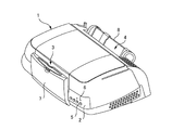
このインクジェットプリンタ1は、図1に示すように、背面から供給された印刷用紙等の媒体を前面から排出する構造を備えており、その前面部には、操作パネル2および排紙部3が設けられ、その背面部には、給紙部4が設けられている。操作パネル2には、各種操作ボタン5および表示ランプ6が設けられている。また、排紙部3には、不使用時に排紙口を塞ぐ排紙トレイ7が設けられている。給紙部4には、カット紙などの媒体を保持するための給紙トレイ8が設けられている。
As shown in FIG. 1, the
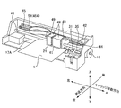
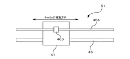
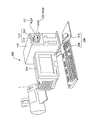
このインクジェットプリンタ1の内部には、図2に示すように、キャリッジ41が設けられている。このキャリッジ41は、左右方向に沿って相対的に移動可能に設けられている。キャリッジ41の周辺には、キャリッジモータ42と、プーリ44と、タイミングベルト45と、ガイドレール46とが設けられている。キャリッジモータ42は、DCモータなどにより構成され、キャリッジ41を左右方向(以下、キャリッジ移動方向ともいう)に沿って相対的に移動させるための駆動源である。タイミングベルト45は、プーリ44を介してキャリッジモータ42に接続されるとともに、その一部がキャリッジ41に接続され、キャリッジモータ42の回転駆動によってキャリッジ41をキャリッジ移動方向(左右方向)に沿って相対的に移動させる。ガイドレール46は、キャリッジ41をキャリッジ移動方向(左右方向)に沿って案内する。
Inside the
この他に、キャリッジ41の周辺には、キャリッジ41の位置を検出するリニア式エンコーダ51と、媒体Sをキャリッジ41の移動方向と交差する方向(図中、前後方向。以下、搬送方向ともいう)に沿って搬送するための搬送ローラ17Aと、この搬送ローラ17Aを回転駆動させる搬送モータ15とが設けられている。
In addition, in the periphery of the
一方、キャリッジ41には、各種インクを収容したインクカートリッジ48と、媒体Sに対して印刷を行うヘッド21とが設けられている。インクカートリッジ48は、例えば、イエロ(Y)やマゼンダ(M)、シアン(C)、ブラック(K)などの各色のインクを収容しており、キャリッジ41に設けられたカートリッジ装着部49に着脱可能に装着されている。また、ヘッド21は、本実施形態では、媒体Sに対してインクを吐出して印刷を施す。このために、ヘッド21には、インクを吐出するための多数のノズルが設けられている。
On the other hand, the
なお、ヘッド21は、媒体Sに対して印刷を施す「印刷ヘッド」に相当する。また、本実施形態では、このヘッド21がキャリッジ41に設けられていることから、キャリッジ41も「印刷ヘッド」に相当する。また、ガイドレール46は、キャリッジ41(ヘッド21)を所定の方向に沿って案内することから、「ガイド部」に相当する。また、キャリッジモータ42は、キャリッジ41(ヘッド21)を移動させるためのモータであることから、「モータ」に相当する。
The
この他に、このインクジェットプリンタ1の内部には、ヘッド21のノズルの目詰まりを解消するためにノズルからインクを吸い出すポンプ装置31や、ヘッド21のノズルの目詰まりを防止するために、印刷を行わないとき(待機時など)にヘッド21のノズルを封止するキャッピング装置35などが設けられている。
In addition to this, in the
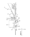
次にこのインクジェットプリンタ1の搬送部について説明する。この搬送部には、図3に示すように、給紙ローラ13と、紙検知センサ53と、搬送ローラ17Aと、排紙ローラ17Bと、プラテン14と、フリーローラ18A、18Bとが設けられている。
Next, the conveyance unit of the
印刷される媒体Sは、給紙トレイ8にセットされる。給紙トレイ8にセットされた媒体Sは、断面略D形状に成形された給紙ローラ13により、図中矢印A方向に沿って搬送されて、インクジェットプリンタ1の内部へと送られる。インクジェットプリンタ1の内部に送られてきた媒体Sは、紙検知センサ53と接触する。この紙検知センサ53は、給紙ローラ13と、搬送ローラ17Aとの間に設置されたもので、給紙ローラ13により給紙された媒体Sを検知する。
紙検知センサ53により検知された媒体Sは、搬送ローラ17Aによって、印刷が実施されるプラテン14へと順次搬送される。搬送ローラ17Aの対向位置には、フリーローラ18Aが設けられている。このフリーローラ18Aと搬送ローラ17Aとの間に、媒体Sを挟み込むことによって、媒体Sをスムーズに搬送する。
プラテン14へと送り込まれた媒体Sは、ヘッド21から吐出されたインクによって順次印刷される。プラテン14は、ヘッド21と対向して設けられ、印刷される媒体Sを下側から支持する。
印刷が施された媒体Sは、排紙ローラ17Bにより順次、プリンタ外部へと排出される。排紙ローラ17Bは、搬送モータ15と同期に駆動されていて、当該排紙ローラ17Bに対向して設けられたフリーローラ18Bとの間に媒体Sを挟み込んで、媒体Sをプリンタ外部へと排出する。
The medium S to be printed is set in the
The medium S detected by the
The medium S sent to the
The medium S on which printing has been performed is sequentially discharged out of the printer by the
<システム構成>
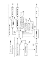
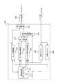
次にこのインクジェットプリンタ1のシステム構成について説明する。このインクジェットプリンタ1は、図4に示すように、バッファメモリ122と、イメージバッファ124と、コントローラ126と、メインメモリ127と、通信インターフェース129と、キャリッジモータ制御部128と、搬送制御部130と、ヘッド駆動部132とを備えている。
<System configuration>
Next, the system configuration of the
通信インターフェース129は、当該インクジェットプリンタ1が、例えばパーソナルコンピュータ等の外部のコンピュータ140とデータのやりとりを行うためのものである。通信インターフェース129は、外部のコンピュータ140と有線または無線等により通信可能に接続され、コンピュータ140から送信された印刷データ等の各種データを受信する。
The
バッファメモリ122には、通信インターフェース129により受信された印刷データ等の各種データが一時的に記憶される。また、イメージバッファ124には、バッファメモリ122に記憶された印刷データが順次記憶される。イメージバッファ124に記憶された印刷データは、順次、ヘッド駆動部132へと送られる。また、メインメモリ127は、ROMやRAM、EEPROMなどにより構成される。メインメモリ127には、当該インクジェットプリンタ1を制御するための各種プログラムや各種設定データなどが記憶される。
Various data such as print data received by the
コントローラ126は、メインメモリ127から制御用プログラムや各設定データなどを読み出して、当該制御用プログラムや各種設定データに従ってインクジェットプリンタ1全体の制御を行う。また、コントローラ126には、ロータリ式エンコーダ134やリニア式エンコーダ51、紙検知センサ53などの各種センサからの検出信号が入力される。
The
コントローラ126は、外部のコンピュータ140から送られてきた印刷データ等の各種データが通信インターフェース129により受信されてバッファメモリ122に格納されると、その格納されたデータの中から必要な情報をバッファメモリ122から読み出す。コントローラ126は、その読み出した情報に基づき、リニア式エンコーダ51やロータリ式エンコーダ134からの出力を参照しながら、制御用プログラムに従って、キャリッジモータ制御部128や搬送制御部130、ヘッド駆動部132などを各々制御する。
When various data such as print data sent from the
キャリッジモータ制御部128は、コントローラ126からの命令に従って、キャリッジモータ42の回転方向や回転数、トルクなどを駆動制御する。搬送制御部130は、コントローラ126からの命令に従って、搬送ローラ17Aを回転駆動する搬送モータ15などを制御する。
ヘッド駆動部132は、コントローラ126からの命令に従って、イメージバッファ124に格納された印刷データに基づき、ヘッド21に設けられた各色のノズルを駆動制御する。
なお、キャリッジモータ制御部128は、本実施形態では、キャリッジ41(ヘッド21)を移動させるためのキャリッジモータ42を制御することから、「モータ制御部」に相当する。
The carriage
The
In this embodiment, the carriage
<ヘッド>
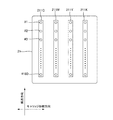
図5は、ヘッド21の下面部に設けられたインクのノズルの配列を示した図である。ヘッド21の下面部には、同図に示すように、イエロ(Y)、マゼンタ(M)、シアン(C)、ブラック(K)の各色ごとにそれぞれ複数のノズル♯1〜♯180からなるノズル列、即ちシアンノズル列211C、マゼンダノズル列211M、イエロノズル列211Y、およびブラックノズル列211Kが設けられている。
<Head>
FIG. 5 is a diagram showing the arrangement of the ink nozzles provided on the lower surface of the
各ノズル列211C、211M、211Y、211Kの各ノズル♯1〜♯180は、所定の方向(ここでは、媒体Sの搬送方向)に沿って相互に間隔をあけて直線状に1列に配列されている。各ノズル列211C、211M、211Y、211Kは、ヘッド21の移動方向(走査方向)に沿って相互に所定の間隔をあけて平行に配置されている。各ノズル♯1〜♯180には、インク滴を吐出するための駆動素子としてピエゾ素子(図示外)が設けられている。
The
===リニア式エンコーダ===
<エンコーダの構成>
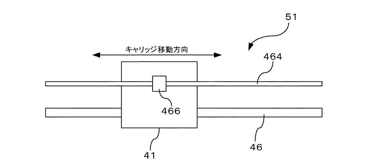
図6は、リニア式エンコーダ51の構成を概略的に示したものである。リニア式エンコーダ51は、リニア式エンコーダ符号板464と、検出部466とを備えている。リニア式エンコーダ符号板464は、図2に示すように、インクジェットプリンタ1内部のフレーム側に取り付けられている。一方、検出部466は、キャリッジ41側に取り付けられている。キャリッジ41がガイドレール46に沿って移動すると、検出部466がリニア式エンコーダ符号板464に沿って相対的に移動する。これによって、検出部466は、キャリッジ41の移動量を検出する。
=== Linear encoder ===
<Configuration of encoder>
FIG. 6 schematically shows the configuration of the
<検出部の構成>
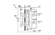
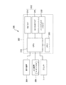
図7は、この検出部466の構成を模式的に示したものである。この検出部466は、発光ダイオード452と、コリメータレンズ454と、検出処理部456とを備えている。検出処理部456は、複数(例えば4個)のフォトダイオード458と、信号処理回路460と、例えば2個のコンパレータ462A、462Bとを有している。
<Configuration of detection unit>
FIG. 7 schematically shows the configuration of the
発光ダイオード452の両端に抵抗を介して電圧Vccが印加されると、発光ダイオード452から光が発せられる。この光はコリメータレンズ454により平行光に集光されてリニア式エンコーダ符号板464を通過する。リニア式エンコーダ符号板464には、所定の間隔(例えば、1/180インチ(1インチ=2.54cm))毎にスリットが設けられている。
When the voltage Vcc is applied to both ends of the
リニア式エンコーダ符号板464を通過した平行光は、図示しない固定スリットを通って各フォトダイオード458に入射し、電気信号に変換される。4個のフォトダイオード458から出力される電気信号は信号処理回路460において信号処理され、信号処理回路460から出力される信号はコンパレータ462A、462Bにおいて比較され、比較結果がパルスとして出力される。コンパレータ462A、462Bから出力されるパルスENC−A、ENC−Bがリニア式エンコーダ51の出力となる。
The parallel light that has passed through the linear
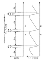
<出力信号>
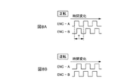
図8A及び図8Bは、キャリッジモータ42の正転時及び逆転時における検出部466の2つの出力信号の波形を示したタイミングチャートである。図8A及び図8Bに示すように、キャリッジモータ42の正転時及び逆転時のいずれの場合も、パルスENC−AとパルスENC−Bとは位相が90度だけ異なっている。キャリッジモータ42が正転しているとき、即ち、キャリッジ41がガイドレール46に沿って移動しているときは、図8Aに示すように、パルスENC−AはパルスENC−Bよりも90度だけ位相が進み、キャリッジモータ42が逆転しているときは、図8Bに示すように、パルスENC−AはパルスENC−Bよりも90度だけ位相が遅れる。そして、パルスENC−A及びパルスENC−Bの1周期Tは、キャリッジ41がリニア式エンコーダ符号板464のスリット間隔を移動する時間に等しい。
<Output signal>
8A and 8B are timing charts showing waveforms of two output signals of the
そして、リニア式エンコーダ51の出力パルスENC−A、ENC−Bの各々の立ち上がりエッジが検出され、検出されたエッジの個数が計数され、この計数値に基づいてキャリッジモータ42の回転位置が演算される。この計数はキャリッジモータ42が正転しているときは1個のエッジが検出されると「+1」を加算し、逆転しているときは、1個のエッジが検出されると「−1」を加算する。パルスENC−A及びENC−Bの各々の周期は、リニア式エンコーダ符号板464の、あるスリットが検出部466を通過してから次のスリットが検出部466を通過するまでの時間に等しく、かつ、パルスENC−AとパルスENC−Bとは位相が90度だけ異なっている。このため、上記計数のカウント値「1」はリニア式エンコーダ符号板464のスリット間隔の1/4に対応する。これにより上記計数値にスリット間隔の1/4を乗算すれば、その乗算値に基づいて、計数値が「0」に対応する回転位置からのキャリッジモータ42の移動量を求めることができる。このとき、リニア式エンコーダ51の解像度はリニア式エンコーダ符号板464のスリットの間隔の1/4となる。
Then, rising edges of the output pulses ENC-A and ENC-B of the
===キャリッジモータ制御部===
キャリッジモータ制御部128の構成について詳しく説明する。図9は、キャリッジモータ制御部128の回路構成の一例を示したブロック構成図である。キャリッジモータ制御部128は、同図に示すように、位置演算部331と、減算器332と、ゲイン333と、速度演算部334と、減算器335と、比例要素336Aと、積分要素336Bと、微分要素336Cと、加算器337と、PWM回路338と、加速制御部339Aと、タイマ339Bとを有する。
=== Carriage motor control unit ===
The configuration of the carriage
位置演算部331は、リニア式エンコーダ51の出力パルスのエッジを検出し、その個数をカウントし、このカウント値に基づきキャリッジモータ42の回転位置を演算する。位置演算部331は、リニア式エンコーダ51からの2つのパルス信号の比較処理からキャリッジモータ42の正転・逆転を認知し、1個のエッジが検出された時に正転・逆転に応じてインクリメント・デクリメントするように計数処理する。なお、この位置演算部331は、「位置検出部」に相当する。
The
減算器332は、コントローラ126から送られてくる目標停止位置と、位置演算部331により検出された検出位置との位置偏差を演算する。ゲイン333は、減算器332から出力される位置偏差にゲインKpを乗算し、目標速度Vtを出力する。ゲインKpは、位置偏差に応じて決定される。
速度演算部334は、リニア式エンコーダ51の出力パルスのパルス周期を計測し、このパルス周期に基づいてキャリッジモータ42の回転速度Vcを演算する。なお、この速度演算部334は、「速度検出部」に相当する。
減算器335は、ゲイン333から出力される目標速度Vtと、速度演算部334により検出された検出速度Vcとの速度偏差ΔVを演算する。
The
The
The
比例要素336Aは、速度偏差ΔVに定数Gpを乗算し、比例成分QPを出力する。積分要素336Bは、速度偏差ΔVに定数Giを乗算したものを1つ前の演算結果QI(j−1)に積算し、積分成分QIを出力する。微分要素336Cは、現在の速度偏差ΔV(j)(ここで、jは時刻を示す)と、1つ前の速度偏差ΔV(j−1)との差に定数Gdを乗算し、微分成分QDを出力する。なお、この微分要素336Cは、「加速度検出部」に相当する。比例要素336A、積分要素336B及び微分要素336Cの演算は、リニア式エンコーダ51の出力パルスの1周期毎に行われる。
The
ここで、各演算要素336A、336B、336Cの演算出力、即ち比例成分QP、積分成分QIおよび微分成分QDは、例えば、次の式(1)〜(3)により与えることができる。
QP(j)=ΔV(j)×Gp ………(1)
QI(j)=QI(j−1)+ΔV(j)×Gi ………(2)
QD(j)={ΔV(j)−ΔV(j−1)}×Gd ………(3)
加算器337は、比例要素336Aの比例成分QPと、積分要素336Bの積分成分QIと、微分要素336Cの微分成分QDとを加算する。これら3つの成分、即ち比例成分QP、積分成分QIおよび微分成分QDの加算結果ΣQは、デューティ信号として、PWM回路338に出力される。
加算結果ΣQは、次の式(4)により得ることができる。
ΣQ(j)=QP(j)+QI(j)+QD(j) ………(4)
PWM回路338は、加算器337の加算結果ΣQに応じた制御信号を生成する。ドライバ340は、この制御信号に基づいてキャリッジモータ42を駆動する。ドライバ340は、例えば複数個のトランジスタを備えており、PWM回路338からの制御信号に基づいて、トランジスタをオン・オフさせることで、キャリッジモータ42に電圧を印加する。
Here, the calculation outputs of the
QP (j) = ΔV (j) × Gp (1)
QI (j) = QI (j−1) + ΔV (j) × Gi (2)
QD (j) = {ΔV (j) −ΔV (j−1)} × Gd (3)
The
The addition result ΣQ can be obtained by the following equation (4).
ΣQ (j) = QP (j) + QI (j) + QD (j) (4)
The
また、加速制御部339A及びタイマ339Bは、キャリッジモータ42の加速制御時に用いられる。タイマ339Bは、コントローラ126から送られてくるクロック信号に基づいて、所定時間毎にタイマ割込信号を発生する。加速制御部339Aは、タイマ割込信号を受ける毎に所定のデューティDXPを積算し、積算結果としてデューティ信号を生成して、このデューティ信号をPWM回路338に出力する。
The
キャリッジモータ42を加速駆動するときには、PWM回路338は、加速制御部339Aから出力されるデューティ信号に基づいて制御信号を生成してキャリッジモータ42を制御する。また、キャリッジモータ42を定速駆動するとき、および、キャリッジモータ42を減速するときには、PWM回路338は、3つの成分、即ち、比例要素336Aの比例成分QP、積分要素336Bの積分成分QI、および微分要素336Cの微分成分QDの加算結果ΣQとして加算器337から出力されたデューティ信号に基づき生成された制御信号をキャリッジモータ42に出力し、キャリッジモータ42を制御する。
When the
===キャリッジモータの駆動方法===
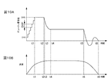
図10Aは、PWM回路338に入力されるデューティ信号の時間変化のグラフである。図10Bは、キャリッジモータ42の速度変化のグラフである。以下、これらの図を用いて、キャリッジモータ42の駆動について説明する。
=== Driving method of carriage motor ===
FIG. 10A is a graph of the time change of the duty signal input to the
キャリッジモータ42が停止している時に、キャリッジモータ42を起動させる起動指令信号がコントローラ126からキャリッジモータ制御部128へ送られると、信号値がDX0である起動初期デューティ信号が加速制御部339AからPWM回路338へ送られる。この起動初期ディユーティ信号は、起動指令信号とともにコントローラ126から加速制御部339Aへ送られてくる。そして、この起動初期ディユーティ信号は、PWM回路338によって、信号値DX0に応じた制御信号に変換されて、キャリッジモータ42の起動が開始される。
When a start command signal for starting the
キャリッジモータ制御部128が起動指令信号を受信した後、所定の時間ごとにタイマ339Bからタイマ割込信号が発生される。加速制御部339Aは、タイマ割込信号を受信する毎に、起動初期デューティ信号の信号値DX0に所定のデューティDXPを積算し、積算されたデューティを信号値とするデューティ信号をPWM回路338に送る。このデューティ信号は、PWM回路338によって、その信号値に応じた制御信号に変換されて、キャリッジモータ42の回転速度は上昇する。このため加速制御部339AからPWM回路338に送られるデューティ信号の値は、階段状に上がっていく。
After the carriage
加速制御部339Aにおけるデューティの積算処理は、積算されたデューティが所定のデューティDXSになるまで行われる。時刻t1において積算されたデューティが所定値DXSとなると、加速制御部339Aは積算処理を停止し、以後PWM回路338に一定のデューティDXSを信号値とするデューティ信号を送る。
The duty integration process in the
そして、キャリッジモータ42が所定の回転速度になると(時間t2参照)、加速制御部339Aは、PWM回路338へ出力するデューティ信号を減少させて、キャリッジモータ42に印加される電圧のデューティパーセントを減少させるよう制御する。このとき、キャリッジモータ42の回転速度は更に上昇する。そして、時間t3になると、PWM回路338は加算器337の出力を選択し、PID制御が行われる。PID制御が開始される時点(t3)において、積分要素336Bの積分値が適当な値に設定されており、積分要素336Bの出力値が所定の値になる。
When the
PID制御が開始されると、キャリッジモータ制御部128は、目標回転位置と、リニア式エンコーダ51の出力から得られる実際の回転位置との位置偏差にゲインKpを乗算して目標速度Vtを算出する。そして、キャリッジモータ制御部128は、この目標速度Vtと、リニア式エンコーダ51の出力から得られる実際の回転速度Vcとの速度偏差ΔVに基づいて、比例要素336A、積分要素336B及び微分要素336Cを用いて比例成分QP、積分成分QI及び微分成分QDの演算を行い、これらの演算結果の和ΣQに基づいて、キャリッジモータ42の制御を行う。尚、上記比例演算、積分演算及び微分演算は、例えば、リニア式エンコーダ51の出力パルスENC−Aの立ち上がりエッジに同期して行われる。これにより、キャリッジモータ42の回転速度は、時刻t4において、所望の回転速度となるように制御される。
When the PID control is started, the carriage
キャリッジモータ42が目標回転位置に近づくと(時刻t5)、位置偏差が小さくなるから目標回転速度も小さくなる。このため、速度偏差、即ち減算器335の出力が負になり、キャリッジモータ42は減速し、時刻t6に停止する。
When the
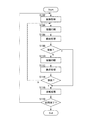
===印刷動作===
次に前述したインクジェットプリンタ1の印刷動作について説明する。ここでは、「双方向印刷」を例にして説明する。図11は、インクジェットプリンタ1の印刷動作の処理手順の一例を示したフローチャートである。以下で説明される各処理は、コントローラ126が、メインメモリ127からプログラムを読み出して、当該プログラムに従って、キャリッジモータ制御部128や搬送制御部130、ヘッド駆動部132などを各々制御することにより実行される。
=== Printing operation ===
Next, the printing operation of the above-described
コントローラ126は、コンピュータ140から印刷データを受信すると、その印刷データに基づき印刷を実行すべく、まず、給紙処理を行う(S102)。給紙処理は、印刷しようとする媒体Sをインクジェットプリンタ1内に供給し、印刷開始位置(頭出し位置とも言う)まで搬送する処理である。コントローラ126は、給紙ローラ13を回転させて、印刷しようとする媒体Sを搬送ローラ17Aまで送る。コントローラ126は、搬送ローラ17Aを回転させて、給紙ローラ13から送られてきた媒体Sを印刷開始位置(プラテン14の上方付近)に位置決めする。
Upon receiving print data from the
次に、コントローラ126は、キャリッジモータ制御部128を通じてキャリッジモータ42を駆動して、キャリッジ41を媒体Sに対して相対的に移動させて媒体Sに対して印刷を施す印刷処理を実行する。ここでは、まず、キャリッジ41をガイドレール46に沿って一の方向に向かって移動させながら、ヘッド21からインクを吐出する往路印刷を実行する(S104)。コントローラ126は、キャリッジモータ42を駆動してキャリッジ41を移動させるとともに、印刷データに基づきヘッド21を駆動してインクを吐出する。ヘッド21から吐出されたインクは、媒体Sに到達してドットとして形成される。
Next, the
このようにして印刷を行った後、次に、コントローラ126は、媒体Sを所定量だけ搬送する搬送処理を実行する(S106)。ここでは、コントローラ126は、搬送制御部130を通じて搬送モータ15を駆動して搬送ローラ17Aを回転させて、媒体Sをヘッド21に対して相対的に搬送方向に所定量だけ搬送する。この搬送処理により、ヘッド21は、先ほどの印刷した領域とは異なる領域に印刷をすることが可能になる。
After printing in this way, the
このようにして搬送処理を行った後、コントローラ126は、排紙すべきか否か排紙判断を実行する(S108)。ここで、コントローラ126は、印刷中の媒体Sに印刷すべき他のデータがなければ、排紙処理を実行する(S116)。一方、コントローラ126は、印刷中の媒体Sに印刷すべき他のデータがあれば、排紙処理は行わずに、復路印刷を実行する(S110)。この復路印刷は、キャリッジ41をガイドレール46に沿って先ほどの往路印刷とは反対の方向に移動させて印刷を行う。ここでも、コントローラ126は、キャリッジモータ制御部128を通じてキャリッジモータ42を先ほどとは逆に回転駆動させてキャリッジ41を移動させるとともに、印刷データに基づきヘッド21を駆動してインクを吐出して、印刷を施す。
After performing the carrying process in this manner, the
復路印刷を実行した後、搬送処理を実行し(S112)、その後、排紙判断を行う(S114)。ここで、印刷中の媒体Sに印刷すべき他のデータがあれば、排紙処理は行わずに、ステップS104に戻って、再度往路印刷を実行する(S104)。一方、印刷中の媒体Sに印刷すべき他のデータがなければ、排紙処理を実行する(S116)。 After performing the return pass printing, a carrying process is executed (S112), and then a paper discharge determination is made (S114). Here, if there is other data to be printed on the medium S being printed, the paper discharge process is not performed, the process returns to step S104, and the forward printing is executed again (S104). On the other hand, if there is no other data to be printed on the medium S being printed, a paper discharge process is executed (S116).
排紙処理を行った後、次に、印刷終了か否かを判断する印刷終了判断を実行する(S118)。ここでは、コンピュータ140からの印刷データに基づき、次に印刷すべき媒体Sがないかどうかチェックする。ここで、次に印刷すべき媒体Sがある場合には、ステップS102に戻り、再び給紙処理を実行して、印刷を開始する。一方、次に印刷すべき媒体Sがない場合には、印刷処理を終了する。
After the paper discharge process is performed, next, a print end determination is performed to determine whether or not to end printing (S118). Here, based on the print data from the
===スティックスリップ動作===
このようなインクジェットプリンタ1にあっては、長期間にわたり使用されなかったりした場合などに、キャリッジ41(印刷ヘッド)がガイドレール46に沿ってうまく滑らなくなり、キャリッジ41の移動速度が周期的に速くなったり遅くなったり、またキャリッジ41が動いたり停まったりする動作を繰り返す、いわゆるスティックスリップ動作(しゃくとり動作ともいう)を行ってしまうことがあった。
=== Stick-slip operation ===
In such an
このスティックスリップ動作にあっては、速度が周期的に速くなったり遅くなったりする動作である。極端な場合には、キャリッジ41が動いたり停まったりする動作を繰り返す、ぎくしゃくとした滑り運動となる。このスティックスリップ動作は、固着すべりともいう。このようなスティックスリップ動作が発生する主な原因としては、キャリッジ41とこれを案内するガイドレール46との間の摺動部の静止摩擦係数と動摩擦係数との差などが原因と考えられる。つまり、キャリッジ41とガイドレール46との間の摺動部の静止摩擦係数が、その動摩擦係数に比べて非常に大きいために、キャリッジモータ42のトルクが上昇してもキャリッジ41がなかなか動かず、キャリッジモータ42のトルクがある程度の大きさになると、キャリッジ41が動き出す。キャリッジ41が動き出すと、動摩擦係数は低いことから、キャリッジ41の移動速度が急激に上昇してしまう。このようにキャリッジ41の移動速度が急激に上昇してしまうと、キャリッジモータ制御部128は、キャリッジ41の移動速度を抑えるべくキャリッジモータ42に急激な制動を加える。このため、キャリッジ41が失速してしまうのである。
In this stick-slip operation, the speed is periodically increased or decreased. In an extreme case, it becomes a jerky sliding motion in which the
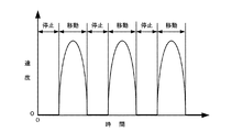
図12は、キャリッジ41がスティックスリップ動作を行ったときのキャリッジ41の移動速度の変化の一例について示したものである。キャリッジ41は、同図に示すように、キャリッジモータ42のトルクがある程度大きくならない限り、動き始めない。キャリッジ41の移動速度は、速度演算部334により検出されている(図9参照)。キャリッジモータ制御部128は、この速度演算部334を通じてキャリッジ41の移動速度を監視している。キャリッジ41の移動速度が上昇しない場合には、キャリッジモータ制御部128は、キャリッジ41を移動させるべく、キャリッジモータ42のトルクを上昇させる制御を行う。これにより、キャリッジモータ42のトルクがある程度大きくなると、キャリッジ41が動き出し、キャリッジ41の移動速度は急激に上昇する。キャリッジ41の移動速度が上昇し、所定のレベルにまで達すると、キャリッジモータ制御部128は、キャリッジ41の移動速度を抑えるべく、キャリッジモータ42に制動を加える。これにより、キャリッジ41の移動速度が低下し、キャリッジ41が失速して再び停止してしまう。そして、キャリッジモータ制御部128は、キャリッジ41を移動させるべく、再びキャリッジモータ42のトルクを上昇させる制御を行う。これにより、キャリッジ41が再び動き出して、急激に移動速度が上昇すると、再びキャリッジ41が失速して停止してしまう。このような移動動作と停止動作とが交互に繰り返される。
FIG. 12 shows an example of a change in the moving speed of the
===スティックスリップ動作が発生する場合===
このようなスティックスリップ動作をキャリッジ41が行うのは、キャリッジモータ制御部128がキャリッジモータ42を介してキャリッジ41を所定の速度以下にて定速移動させようとした場合である。つまり、キャリッジ41が所定の速度を上回る速度にて定速移動する場合、即ち例えば、キャリッジ41が、印刷実行時等において非常に高速で移動する場合には、スティックスリップ動作はほとんど発生しない。ここでいう所定の速度とは、キャリッジ41がスティックスリップ動作を行う可能性のある上限の速度のことをいう。
=== When stick-slip motion occurs ===
The
キャリッジ41がスティックスリップ動作を行うような所定の速度以下で定速移動する場合としては、例えば、次の(1)〜(4)の場合がある。
Examples of cases where the
(1)インクカートリッジ交換時
キャリッジ41に搭載されたインクカートリッジ48(図2参照)がユーザー等により交換される場合である。インクカートリッジ48がユーザー等により交換される場合には、インクカートリッジ48がユーザー等により交換し易いように所定の位置までキャリッジ41を移動させる必要がある。この場合に、ユーザー等が不用意にキャリッジ41と接触しないようにするために、キャリッジ41を所定の速度以下にてゆっくりと低速移動させる必要がある。
(1) Ink cartridge replacement In this case, the ink cartridge 48 (see FIG. 2) mounted on the
(2)キャッピング時
キャリッジ41がキャッピング装置35(図2参照)が設けられた位置まで移動する場合である。印刷を行わないとき(待機時など)などには、ヘッド21のノズル♯1〜♯180の目詰まりを防止するために、キャリッジ41がキャッピング装置35の設置位置まで移動してヘッド21のノズル♯1〜♯180を封止する動作が行われる。このような場合に、キャリッジ41を所定の速度以下にてゆっくりと低速移動させる。
(2) During capping When the
(3)電源投入時
電源が投入されたときに、キャリッジ41がキャッピング装置35から離れて、印刷処理の実行準備、例えば、ヘッド21のノズル♯1〜♯180のクリーニング等を行うために、イニシャル動作を開始する。このような場合に、キャリッジ41を所定の速度以下にてゆっくりと低速移動させる。
(3) When the power is turned on When the power is turned on, the
(4)紙幅検出時
キャリッジ41に設けられた光学センサ(図示外)により、インクジェットプリンタ1がこれから印刷しようとする媒体Sの幅を検出するために、キャリッジ41がガイドレール46に沿って移動する。このとき、媒体Sの幅を精度良く調べるために、キャリッジ41が所定の速度以下にてゆっくりと低速移動する。
(4) During paper width detection The
なお、キャリッジ41がスティックスリップ動作を行うような所定の速度以下で定速移動する場合にあっては、これら(1)〜(4)以外の他の場合であっても良い。
In the case where the
===スティックスリップ動作の判定方法===
このようなスティックスリップ動作をキャリッジ41が行った場合、キャリッジ41を目標停止位置にてスムーズに停止させることができず、ヘッド21が目標停止位置付近にて行ったり来たりするなどの不具合が発生することがあった。これによって、ユーザーが故障ではないかと不安に思う虞があった。このようなことから、ヘッド21がスティックスリップ動作を行ったときには、これを速やかに検知して、ヘッド21を目標停止位置にて停止させることができるように対応する必要がある。
=== Judgment method of stick-slip motion ===
When the
そこで、本実施形態に係るインクジェットプリンタ1では、キャリッジ41がこのようなスティックスリップ動作を行った場合に、スムーズに対応することができるようにするために、キャリッジ41がスティックスリップ動作を行ったか否かを判定することができる。なお、ここでは、キャリッジ41がスティックスリップ動作を行ったか否かの判定は、コントローラ126により行う。コントローラ126は、「判定部」に相当する。スティックスリップ動作の判定方法としては、例えば、次の(1)〜(4)の方法がある。
Therefore, in the
(1)移動速度に基く判定
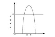
キャリッジ41の移動速度に基づき、キャリッジ41がスティックスティック動作を行ったか否か判定する。この判定方法の1つとして、キャリッジ41の移動速度が所定のしきい値V0を超えたときに、キャリッジ41がスティックスリップ動作を行っていると判定する方法がある。キャリッジ41がスティックスリップ動作を行った場合には、図13Aに説明するように、キャリッジ41の移動速度は、キャリッジ41が動き出すと、急激に上昇する。このときのキャリッジ41の移動速度は、本来のキャリッジ41の移動速度よりもずっと速い速度にまで達する。このことから、適当な所定のしきい値V0を設定して、キャリッジ41の移動速度が、この所定のしきい値V0を超えたか否かを調べることで、キャリッジ41がスティックスリップ動作を行ったか否か簡単にチェックすることができる。
(1) Determination Based on Moving Speed Based on the moving speed of the
この他に、キャリッジ41の移動速度に基づき、キャリッジ41がスティックスリップ動作を行ったか否かを判定する方法としては、図13Bにて説明するように、キャリッジ41の移動速度が所定の上限許容値V1を超え、かつその後、所定の下限許容値V2を下回ったときに、キャリッジ41がスティックスリップ動作を行っていると判定する方法がある。キャリッジ41がスティックスリップ動作を行った場合には、同図に示すように、キャリッジ41の移動速度が、キャリッジ41が動き出すと急激に上昇し、そして急激に減少する。最終的には、キャリッジ41は失速して停止状態に近くなる場合がある。キャリッジ41の移動速度は、本来想定されるキャリッジ41の移動速度の上限許容値V1よりもずっと速い速度に達し、かつその後、急激に低下して本来想定されるキャリッジ41の移動速度の下限許容値V2よりも低い速度(停止状態も含む)に達する。このことから、キャリッジ41がスティックスリップ動作を行ったか否か簡単に判定することができる。
In addition to this, as a method for determining whether or not the
なお、ここで、キャリッジ41がスティックスリップ動作を行ったか否かの判定にあっては、キャリッジ41の移動速度が所定のしきい値V0を超えた回数を計数して、その回数が所定の回数(例えば、2回等)を超えたとき、キャリッジ41がスティックスリップ動作を行っていると判定しても良い。また、キャリッジ41の移動速度が所定の上限許容値V1を超え、かつその後、所定の下限許容値V2を下回った回数を計数して、その回数が所定の回数(例えば、2回等)を超えたときに、キャリッジ41がスティックスリップ動作を行っていると判定しても良い。
Here, in determining whether or not the
(2)制御信号に基づく判定
キャリッジモータ制御部128がキャリッジモータ42を制御するために生成する制御信号に基づき、キャリッジ41がスティックスリップ動作を行ったか否かを判定する。ここで、制御信号としては、例えば、キャリッジモータ制御部128のPWM回路338(図9参照)に入力されるデューティ信号に基づき判定をする。
(2) Determination Based on Control Signal Based on the control signal generated for the carriage
図14Aは、キャリッジ41がスティックスリップ動作を行ったときのキャリッジ41の移動速度と、PWM回路338に入力されるデューディ信号の信号値との関係について説明したものである。キャリッジ41がスティックスリップ動作を行ったときには、キャリッジ41の移動速度は、同図の上段に示すように、急激に上昇して、その後、急激に低下する。そして、キャリッジ41は、このような移動動作と、停止動作とを交互に繰り返す。
FIG. 14A illustrates the relationship between the movement speed of the
一方、キャリッジモータ制御部128のPWM回路338に入力されるデューティ信号の信号値は、同図の下段に示すように、キャリッジ41が移動を開始するまでの間、徐々に上昇する。そして、キャリッジ41が移動を開始して、キャリッジ41の移動速度が急激に上昇すると、キャリッジモータ制御部128は、キャリッジ41の移動速度を抑制させるべく、キャリッジモータ42の駆動力を急速に低下させる。これにより、PWM回路338に入力されるデューディ信号の信号値が急激に減少する。その後、キャリッジ41が停止すると、キャリッジモータ制御部128は、キャリッジ41の移動速度を上昇させて移動を開始させるべく、PWM回路338に入力されるデューディ信号の信号値を徐々に上昇させる。そして、そのデューディ信号の信号値が所定のレベルに達すると、キャリッジ41が移動を開始する。キャリッジ41の移動が開始すると、再びキャリッジモータ制御部128がキャリッジ41の移動速度を抑制させるために、キャリッジモータ42の駆動力を急速に低下させる。これによって、PWM回路338に入力されるデューディ信号の信号値が再び急激に減少する。PWM回路338に入力されるデューディ信号の信号値は、このようにキャリッジ41の移動速度に応じて増減変動を繰り返す。
On the other hand, the signal value of the duty signal input to the
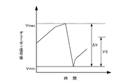
実際に、キャリッジ41がスティックスリップ動作を行ったか否か判定する方法としては、ここでは、PWM回路338に入力されるデューディ信号の信号値の極大値Vmaxと極小値Vminとを調べ、その極大値Vmaxと極小値Vminとの差ΔVに基づき、キャリッジ41がスティックスリップ動作を行ったか否か判定する。つまり、デューディ信号の信号値の極大値Vmaxと極小値Vminとの差ΔVが、所定のしきい値V0を超えたか否かチェックし、その差ΔVが所定のしきい値V0を超えていたときには、キャリッジ41がスティックスリップ動作を行っていると判定する。一方、デューディ信号の信号値の極大値Vmaxと極小値Vminとの差ΔVが、所定のしきい値V0を超えなかった場合には、キャリッジ41がスティックスリップ動作を行わなかったと判定する。
In practice, as a method for determining whether or not the
図14Bは、その判定方法の一例について詳しく説明したものである。まず、デューディ信号の信号値の極大値Vmaxと極小値Vminとを取得する。その取得した極大値Vmaxおよび極小値Vminから差ΔVを求める。キャリッジ41がスティックスリップ動作を行った場合には、同図に示すように、デューディ信号の信号値の極大値Vmaxと極小値Vminとの間に差ΔVが大きな値になる。この差ΔVを予め定めておいた所定のしきい値V0と比較することで、キャリッジ41がスティックスリップ動作を行ったか否か簡単に判定することができる。
FIG. 14B explains in detail an example of the determination method. First, the maximum value Vmax and the minimum value Vmin of the signal value of the due signal are acquired. A difference ΔV is obtained from the acquired maximum value Vmax and minimum value Vmin. When the
なお、ここで、キャリッジ41がスティックスリップ動作を行ったか否かの判定にあっては、PWM回路338に入力されるデューディ信号の信号値の極大値Vmaxと極小値Vminとの差ΔVが所定のしきい値V0を超えることが所定回数以上(例えば、2回以上等)発生した場合に、キャリッジ41がスティックスリップ動作を行っていると判定しても良い。
Here, in determining whether or not the
また、制御信号に基づきキャリッジ41がスティックスリップ動作を行ったか否かを判定する方法としては、デューディ信号の信号値の極大値Vmaxと極小値Vminとの差ΔVに基づき判定する以外に、他の方法により判定しても良い。
Further, as a method for determining whether or not the
(3)加速度に基づく判定
ここでは、キャリッジ41の加速度に基づき、キャリッジ41がスティックスリップ動作を行ったか否かを判定する。ここで、加速度は、キャリッジモータ制御部128の速度演算部334(図9参照)により取得する。つまり、速度演算部334は、リニア式エンコーダ51からの出力に基づき検出したキャリッジ41の移動速度を所定の時間間隔にて周期的に出力する。コントローラ126は、速度演算部334から周期的に送られてきたキャリッジ41の移動速度の差分からキャリッジ41の加速度を取得し、この差分に基づき、キャリッジ41がスティックスリップ動作を行ったか否かを判定する。
(3) Determination Based on Acceleration Here, it is determined based on the acceleration of the
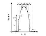
図15は、キャリッジ41の加速度に基づきスティックスリップ動作を行ったか否かを判定する方法の一例を説明したものである。キャリッジ41がスティックスリップ動作を行った場合、キャリッジ41の移動速度は、同図に示すように、急激に上昇して、その後、急激に低下する。このようにして、キャリッジ41の加速度が非常に大きくなることから、この加速度に着目すれば、キャリッジ41がスティックスリップ動作を行ったか否か判定することができる。
FIG. 15 illustrates an example of a method for determining whether or not a stick-slip operation has been performed based on the acceleration of the
コントローラ126は、キャリッジモータ制御部128の速度演算部334から所定の時間間隔T0にて周期的にキャリッジ41の移動速度V1〜V6を取得する。そして、コントローラ126は、取得したキャリッジ41の移動速度V1〜V6から差分を加速度として逐次算出する。つまり、コントローラ126は、移動速度V1と移動速度V2とから「V2−V1」により差分ΔV21を、また、移動速度V2と移動速度V3とから「V3−V2」により差分ΔV32を、移動速度V3と移動速度V4とから「V4−V3」により差分ΔV43を、移動速度V4と移動速度V5とから「V5−V4」により差分ΔV54を、移動速度V5と移動速度V6とから「V6−V5」により差分ΔV65をそれぞれ算出する。
The
そして、コントローラ126は、求めた差分ΔV21、ΔV32、ΔV43、ΔV54、ΔV65を所定のしきい値V0と比較して、その差分ΔV21、ΔV32、ΔV43、ΔV54、ΔV65が所定のしきい値V0を上回ったか否かをチェックする。その差分ΔV21、ΔV32、ΔV43、ΔV54、ΔV65が所定のしきい値V0を上回っていた場合には、コントローラ126は、キャリッジ41がスティックスリップ動作を行っていると判定する。一方、その差分ΔV21、ΔV32、ΔV43、ΔV54、ΔV65が所定のしきい値V0を上回っていなかった場合には、コントローラ126は、キャリッジ41がスティックスリップ動作を行っていないと判定する。
The
なお、ここでは、キャリッジ41の加速時に着目してキャリッジ41がスティックスリップ動作を行ったか否かを判定していたが、この他に、キャリッジ41の減速時、即ちマイナス(−)の加速度(減速度)に着目して、キャリッジ41がスティックスリップ動作を行ったか否かを判定しても良い。
Here, it is determined whether or not the
また、キャリッジ41がスティックスリップ動作を行ったか否かの判定にあっては、求めた差分が所定のしきい値V0を上回った回数が所定回数以上(例えば、2回以上等)発生した場合に、キャリッジ41がスティックスリップ動作を行っていると判定しても良い。
In determining whether or not the
(4)所定の許容速度以下の時間に基づく判定
ここでは、キャリッジ41の移動開始から移動終了までの間に、キャリッジ41の移動速度が所定の許容下限値以下になった時間を計測するタイマーの計測時間に基づき、キャリッジ41がスティックスリップ動作を行ったか否かを判定する。
(4) Determination Based on Time Less Than Predetermined Allowable Speed Here, a timer that measures the time during which the movement speed of the
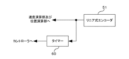
図16Aは、キャリッジモータ制御部128に設けられたタイマー60について説明したものである。タイマー60には、同図に示すように、リニア式エンコーダ51から速度演算部334や位置演算部331へと出力される出力信号が入力される。タイマー60は、リニア式エンコーダ51の出力信号を監視し、キャリッジ41の移動速度が所定の許容下限値以下になったとき、時間計測を開始する。ここでは、タイマー60は、リニア式エンコーダ51からの出力信号のパルスの周期が所定の周期よりも長くなったときに、時間計測を開始する。キャリッジ41の移動速度が所定の許容下限値以下ではなくなった場合には、タイマー60は時間計測を中止する。これにより、タイマー60は、キャリッジ41の移動速度が所定の許容下限値以下になった時間を計測する。タイマー60の計測時間に関する情報は、コントローラ126に伝達される。コントローラ126は、タイマー60から取得した計測時間に関する情報に基づき、キャリッジ41がスティックスリップ動作を行ったか否かを判定する。
FIG. 16A illustrates the
図16Bは、キャリッジ41がスティックスリップ動作を行ったか否かを判定する方法の一例を説明したものである。キャリッジ41がスティックスリップ動作を行った場合には、同図に示すように、キャリッジ41の移動速度が、急激に上昇して、急激に低下する。そして、キャリッジ41は、しばらく時間が経過してから再び移動を開始する。キャリッジ41は、移動開始から移動終了までの間に、このような移動動作と停止動作とを交互に繰り返す。
FIG. 16B illustrates an example of a method for determining whether or not the
一方、キャリッジ41がスティックスリップ動作を行わない場合には、通常、このような移動動作と停止動作とを交互に繰り返すことはない。つまり、キャリッジ41は、移動を開始してから移動を終了するまでの間に、所定時間以上、移動速度が所定の許容下限値以下になることはないのである。このことから、キャリッジ41が移動を開始した後、キャリッジ41の移動速度が所定の許容下限値VLを下回った時間Tを計測することで、キャリッジ41がスティックスリップ動作を行ったか否かを調べることができる。なお、ここで、所定の許容下限値VLは、キャリッジ41がスティックスリップ動作を行わずに移動した場合に、キャリッジ41の移動速度としては想定することができない十分に低い速度に設定される。この所定の許容下限値VLは、例えば、キャリッジ41が停止したときに時間計測を行うために、『0(ゼロ)』に近い値に設定されても良い。
On the other hand, when the
タイマー60は、リニア式エンコーダ51の出力信号を監視し、リニア式エンコーダ51からの出力信号のパルスの周期が所定の周期よりも長くなると、キャリッジ41の移動速度が所定の許容下限値VL以下であると判断して、時間計測を開始する。タイマー60による時間計測は、キャリッジ41の移動速度が所定の許容下限値VLを超えたと判断されるまで行われる。これにより、タイマー60は、キャリッジ41の移動速度が所定の許容下限値VLを下回った時間Tを計測する。タイマー60の計測結果は、タイマー60からコントローラ126へと伝達される。ここで、タイマー60からコントローラ126へは、タイマー60の計測時間Tがリアルタイムで伝達されてもよく、また、タイマー60による時間計測が終了した後、タイマー60の計測時間Tが伝達されても良い。
The
コントローラ126は、タイマー60から伝達された計測時間Tと、所定のしきい値T0とを比較して、計測時間Tが所定のしきい値T0に達していた場合には、キャリッジ41がスティックスリップ動作を行っていると判定する。一方、タイマー60の計測時間Tが所定のしきい値T0に達していなかった場合には、コントローラ126は、キャリッジ41がスティックスリップ動作を行っていないと判定する。
The
なお、ここで、キャリッジ41がスティックスリップ動作を行ったか否かの判定にあっては、計測時間Tが所定のしきい値T0に達した回数を計数して、その回数が所定回数以上(例えば、2回以上等)発生した場合に、キャリッジ41がスティックスリップ動作を行っていると判定しても良い。
また、キャリッジ41がスティックスリップ動作を行ったか否かを判定する方法としては、これら(1)〜(4)以外の他の方法により実施しても良い。
Here, in determining whether or not the
Further, as a method for determining whether or not the
===スティックスリップ動作に対する対応===
本実施形態にかかるインクジェットプリンタ1では、このようにしてキャリッジ41がスティックスリップ動作を行っていると判定された場合に、キャリッジ41を目標停止位置にてスムーズに停止させることができるようにするために、次のような対応策を実行する。
=== Corresponding to stick-slip operation ===
In the
ここでは、キャリッジ41がスティックスリップ動作を行っていると判定された場合に、キャリッジモータ制御部128がキャリッジモータ42に対して、スティックスリップ動作を行っていると判定されていない場合に比べて大きなブレーキ力にてブレーキ制御を実行してキャリッジ41を目標停止位置にて停止させる。これにより、キャリッジ41を目標停止位置にて的確に停止させることができるようにする。
Here, when it is determined that the
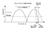
図17Aおよび図17Bは、キャリッジ41がスティックスリップ動作を行っていると判定されたときに、キャリッジモータ42に対して大きなブレーキ力にてブレーキ制御を実行した場合と、実行しなかった場合について説明したものである。図17Aは、大きなブレーキ力にてブレーキ制御を実行しなかった場合の一例について説明したものである。図17Bは、大きなブレーキ力にてブレーキ制御を実行した場合の一例について説明したものである。
FIGS. 17A and 17B illustrate a case where brake control is executed with a large brake force on the
キャリッジ41がスティックスリップ動作を行っていると判定されたときに、キャリッジモータ42に対して大きなブレーキ力にてブレーキ制御を実行しなかった場合には、図17Aに示すように、ブレーキ力が弱いためにキャリッジ41を目標停止位置P0にて的確に停止させることができないことがある。すなわち、ブレーキ力が弱いことから、キャリッジ41を十分に減速することができず、目標停止位置P0を通過してしまうことがある。これは、キャリッジ41が目標停止位置P0から所定の距離Lだけ手前のブレーキ制御開始位置P1に到達したときに、キャリッジ41の移動速度が所定の想定速度Vsを超えていた場合に発生する。つまり、通常のブレーキ力は、キャリッジ41がスティックスリップ動作を行っていないことを前提に、例えば、ブレーキ制御開始時のキャリッジ41の移動速度が所定の想定速度Vs以下であるとして設定されている。キャリッジモータ42に対してブレーキ制御を開始しようとしたときに、キャリッジ41の移動速度が所定の想定速度Vsを超えていたときには、通常のブレーキ力ではキャリッジ41を十分に減速させることができず、キャリッジ41が目標停止位置P0に到達しても、キャリッジ41の移動速度を十分に下げることができない。このため、キャリッジ41は、目標停止位置P0を過ぎて、例えば、実際の停止位置P3等に停止することになる。つまり、キャリッジモータ42に対して大きなブレーキ力にてブレーキ制御を実行しなかった場合には、キャリッジ41を所定の目標停止位置にて的確に停止させることができないことがある。
When it is determined that the
一方、キャリッジモータ42に対して大きなブレーキ力にてブレーキ制御を実行した場合には、図17Bに示すように、キャリッジ41がブレーキ制御開始位置P1に到達したときに、キャリッジ41の移動速度が所定の想定速度Vsを超えていた場合であっても、ブレーキ力が大きいことから、キャリッジ41を十分に減速させることができる。つまり、ブレーキ力が大きいことによって、キャリッジ41の移動速度の低下率(図17B中のブレーキ制御区間の実線の傾斜)が、大きなブレーキ力にてブレーキ制御を実行しなかった場合図17A中のブレーキ制御区間の実線の傾斜)に比べて大きく、これにより、キャリッジ41が目標停止位置P0に到達したときにキャリッジ41を十分に停止させることができる。つまり、キャリッジ41の移動速度が所定の測定速度Vsを超えていた場合であっても、キャリッジ41を目標停止位置にて的確に停止させることが可能である。
On the other hand, when brake control is executed with a large braking force on the
《ブレーキ制御》
ブレーキ制御とは、キャリッジ41を停止または減速させるための制御のことをいう。本実施形態では、キャリッジモータ制御部128は、生成する制御信号の信号値を小さくすることによりブレーキ制御を実施することになる。実際には、キャリッジ41が目標停止位置P0に近付くと、コントローラ126からの目標停止位置P0と、位置演算部331により検出された現在位置との位置偏差が減少して、図9にて説明したPWM回路338からドライバ340に制御信号として信号値の小さい制御信号または負の信号値の制御信号が出力されることになる。
《Brake control》
Brake control refers to control for stopping or decelerating the
本実施形態のキャリッジモータ制御部128において、ブレーキ制御のブレーキ力を大きくする方法としては、ゲイン333のゲインKpや、比例要素336Aの定数Gp、積分要素336Bの定数Gi、微分要素336Cの定数Gdを適宜変更して制御量を増大させる方法が考えられる。つまり、これらゲインKpや定数Gp、Gi、Gdを変更することによって、加算器337に入力される成分QP、QI、QDの大きさを調整して、加算器337からPWM回路338に出力される加算結果ΣQを変えて、これにより、PWM回路338から、キャリッジモータ42に対するブレーキ力が大きくなるような制御信号が出力されるようにする。
In the carriage
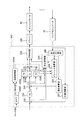
この他に、キャリッジ41を目標停止位置P0に停止させるためのブレーキ制御としては、次のようなブレーキ制御専用の制御部を備えた構成がある。図18は、このブレーキ制御専用の制御部を備えたキャリッジモータ制御部の構成の一例を説明したものである。
In addition to this, as brake control for stopping the
このキャリッジモータ制御部342は、図9に示すキャリッジモータ制御部128と同様、位置演算部331と、減算器332と、ゲイン333と、速度演算部334と、減算器335と、比例要素336Aと、積分要素336Bと、微分要素336Cと、加算器337と、PWM回路338と、加速制御部339Aと、タイマ339Bとを備えている。この他に、このキャリッジモータ制御部342は、停止制御部344と、イナーシャ演算部346と、周期計測部348とを備えている。これらのうち、停止制御部344およびイナーシャ演算部346は、ブレーキ制御専用の制御部を構成し、キャリッジ41を停止させるために用いられる。
As with the carriage
周期計測部84は、リニア式エンコーダ51の出力パルスENC−Aの1周期、例えば、立上りエッジから次の立上りエッジまでの時間を計測することにより、周期を計測する。周期計測部84の出力は、速度演算部334およびイナーシャ演算部346に入力される。
The period measurement unit 84 measures the period by measuring one period of the output pulse ENC-A of the
イナーシャ演算部346は、周期計測部348の出力と、加速制御部339Aの出力および積分要素336Bの出力に基づいて、キャリッジ41のイナーシャ(慣性モーメント)を演算する。図19は、このイナーシャ演算部346の構成の一例を説明したものである。イナーシャ演算部346は、メモリ347Aと、タイマ347Bと、演算部347Cとを備えている。メモリ347Aは、加速制御部339Aから、指令信号を受信した後に周期計測部348から送られてくる2番目の周期T2と、k(k≧3)番目の周期Tkとを記憶する。ここで、指令信号は、加速制御部339AがPWM回路338へ出力するデューディ信号が所定の目標値Iaccに達したときに加速制御部339Aから出力される。また、周期T2およびTkは、加速制御部339Aから信号値Iaccの信号が出力されているときの値である。kは、制御に応じて予め決めておく。
The
タイマ347Bは、2番目の周期T2を受信してからk番目の周期Tkを受信するまでの時間Ttをカウントする。なお、タイマ347Bは、カウントを実行する代わりに、2番目の周期T2からk番目の周期Ti(i=2,…………k)を積算して求めても良い。この場合、「Tt=T3+T4+…………+Tk」となる。
The
演算部347Cは、IaccおよびT2、Tk、Ttと、キャリッジ41(キャリッジモータ42)が定速領域から減速領域(ブレーキ制御領域)に移る直前の積分要素336Bの出力Ifとに基づいてキャリッジ41のイナーシャJを算出する。
The
停止制御部344は、減算器335の出力と、減算器335の出力が所定値以下になったときの周期計測部348からの出力Tfと、キャリッジ41(キャリッジモータ42)が定速領域から減速領域(ブレーキ制御領域)に移る直前の積分要素336Bの出力Ifと、演算部により算出されたイナーシャJとに基づいて、キャリッジ41を目標停止位置に停止させるためにPWM回路338に入力すべきデューディ値Istopを次の関係式(6)により算出する。
The
停止制御部344は、算出したデューディ値IstopをPWM回路338に向けて出力する。PWM回路338は、キャリッジ41(キャリッジモータ42)が定速領域から減速領域(ブレーキ制御領域)に移行した際に停止制御部344からの出力を選択する。
The
このようにキャリッジ41(キャリッジモータ42)が定速領域から減速領域(ブレーキ制御領域)に移行した際に、PWM回路338が停止制御部344からの出力を選択することで、キャリッジモータ制御部342は、キャリッジ41のイナーシャ(慣性モーメント)に応じた制御信号をPWM回路338から出力してキャリッジモータ42を停止制御することができる。これにより、キャリッジ41がスティックスリップ動作を行っていると判定された場合には、キャリッジ41を停止させる際に、キャリッジモータ42に対してより大きなブレーキ力にてブレーキ制御を実行することができる。したがって、キャリッジ41を目標停止位置に的確に停止させることができる。
Thus, when the carriage 41 (carriage motor 42) shifts from the constant speed region to the deceleration region (brake control region), the
この他に、ブレーキ制御としては、ブレーキ機構(減速機構)等によりキャリッジ41の移動やキャリッジモータ42の回転駆動を外部から機械的に抑制する制御方法もある。
In addition, as a brake control, there is a control method for mechanically suppressing the movement of the
《コントローラの処理》
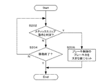
図20は、コントローラ126の対応処理の一例を説明したフローチャートである。コントローラ126は、キャリッジモータ制御部128がキャリッジ41を所定の速度以下にて定速移動させようとした際に、まず、キャリッジ41がスティックスリップ動作を行っていると判定されたか否かをチェックする(S202)。ここで、キャリッジ41がスティックスリップ動作を行っていると判定されていない場合には、コントローラ126は、次にステップS204へと進み、キャリッジ41の移動が終了したか否かをチェックする(S204)。
<Controller processing>
FIG. 20 is a flowchart illustrating an example of the handling process of the
キャリッジ41の移動が終了していない場合には、コントローラ126は、ステップS202へと戻り、再び、キャリッジ41がスティックスリップ動作を行っていると判定されたか否かチェックする(S202)。キャリッジ41がスティックスリップ動作を行っていると判定されたか否かのチェックは、キャリッジ41の移動が終了するまでの間、コントローラ126により実施される。キャリッジ41の移動が終了した場合には、コントローラ126は、処理を速やかに終了する。
If the movement of the
一方、ステップS202において、キャリッジ41がスティックスリップ動作を行っていると判定された場合には、コントローラ126は、次にステップS206へと進み、キャリッジ41を目標停止位置に停止させるときにキャリッジモータ制御部128が実行するブレーキ制御のブレーキ力がより大きな値になるようにセットする(S206)。その後、コントローラ126は、処理を速やかに終了する。
On the other hand, if it is determined in step S202 that the
===まとめ===
本実施形態にあっては、キャリッジ41がスティックスリップ動作を行っていると判定された場合には、キャリッジモータ制御部128がキャリッジモータ42に対して、キャリッジ41がスティックスリップ動作を行っていると判定されていない場合よりも大きなブレーキ力にてブレーキ制御を実行するから、キャリッジ41を停止させる際には、キャリッジ41を十分に減速させることができる。これにより、キャリッジ41を目標停止位置にて的確に停止させることができる。
=== Summary ===
In the present embodiment, when it is determined that the
===他のキャリッジモータ制御部の構成例===
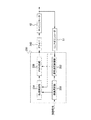
図21は、キャリッジモータ制御部の他の構成例について説明したものである。このキャリッジモータ制御部350は、図21に示すように、通常速度制御部352と、低速制御部354と、制御選択部356と、PWM回路338とを備えている。ここで、通常速度制御部352は、キャリッジ41を通常速度で移動させるための制御部である。また、低速制御部354は、キャリッジ41を先に説明したように所定の速度以下にて低速移動させるための制御部である。これら通常速度制御部352および低速制御部354については、後で詳しく説明する。
=== Configuration Example of Other Carriage Motor Control Unit ===
FIG. 21 illustrates another configuration example of the carriage motor control unit. The carriage
制御選択部356は、コントローラ126からの命令によって、これら通常速度制御部352および低速制御部354のうちのいずれか一方を選択する。そして、制御選択部356により選択された2つの制御部、即ち通常速度制御部352および低速制御部354のうちのいずれか一方からの出力がPWM回路338に入力される。PWM回路338は、通常速度制御部352または低速制御部354からの出力に基づいて、キャリッジモータ42を制御するための制御信号を生成する。
The
《通常速度制御部》
ここで、通常速度制御部352は、例えば、図9にて説明したような、PID制御にてキャリッジモータ42の制御を行うような制御部により構成される。具体的には、例えば、図9に用いて説明したように、リニア式エンコーダ51の出力パルスに基づきキャリッジモータ42の回転位置を演算する位置演算部331と、コントローラ126から送られてくる目標停止位置と、位置演算部331により検出された検出位置との位置偏差を演算する減算器332と、減算器332から出力される位置偏差にゲインKpを乗算して目標速度Vtを出力するゲイン333と、リニア式エンコーダ51の出力パルスに基づきキャリッジモータ42の回転速度Vcを演算する速度演算部334と、ゲイン333から出力される目標速度Vtと、速度演算部334により検出された検出速度Vcとの速度偏差ΔVを演算する減算器335と、速度偏差ΔVに定数Gpを乗算し、比例成分QPを出力する比例要素336Aと、速度偏差に定数Giを乗算したものを積算し、積分成分QIを出力する積分要素336Bと、現在の速度偏差ΔV(j)(ここで、jは時刻を示す)と、1つ前の速度偏差ΔV(j−1)との差に定数Gdを乗算し、微分成分QDを出力する微分要素336Cと、これら各演算要素336A、336B、336Cの演算出力QP、QIおよびQDを加算する加算器337とを備えている。そして、この加算器337の加算結果が、図21に示すように、通常速度制御部352から出力されてPWM回路338に入力される。
《Normal speed control unit》
Here, the normal
なお、通常速度制御部352にあっては、キャリッジモータ42を加速制御するために、図9にて説明したような、コントローラ126から送られてくるクロック信号に基づいて、所定時間毎にタイマ割込信号を発生するタイマ339Bと、タイマ割込信号を受ける毎に所定のデューティDXPを積算し、その積算結果としてデューティ信号を生成して出力する加速制御部339Aとを備えても良い。このようなタイマ339Bと加速制御部339Aとを備えれば、キャリッジモータ42をスムーズに加速制御することができる。
In the normal
一方、低速制御部354は、キャリッジ41を低速にて移動させるための制御部である。例えば、この低速制御部354は、前述したようなキャリッジ41を所定の速度以下にて定速移動させる場合などに利用される。以下にこの低速制御部354の具体的な構成例について説明する。
On the other hand, the low
《低速制御部》
図22は、低速制御部354の一例について説明したものである。この低速制御部354は、同図に示すように、ホールド制御部360と、タイマ割込制御部362と、エンコーダ割込制御部364と、周期カウンタ366と、位置カウンタ368と、制御選択部370と、タイマカウンタ372と、第一選択部374と、微分速度制御部376と、第二選択部378とを備えている。
《Low speed control unit》
FIG. 22 illustrates an example of the low
なお、ホールド制御部360は、キャリッジ41が目標停止位置に到達したときにキャリッジモータ42を制御するための制御部である。また、タイマ割込制御部362は、キャリッジ41が停止しているとき、またはキャリッジ41がかなりゆっくりと移動しているときに、キャリッジモータ42を制御するための制御部である。また、エンコーダ割込制御部364は、キャリッジ41がある程度の速度にて移動しているときにキャリッジモータ42を制御するための制御部である。
The
位置カウンタ368は、リニア式エンコーダ51の出力パルスを計数して、その計数結果をパルスとして出力する。また、周期カウンタ366は、リニア式エンコーダ51の出力パルスからその周期を検出して出力する。
The position counter 368 counts the output pulses of the
制御選択部370は、位置カウンタ368からの出力に基づき、ホールド制御部360、タイマ割込制御部362およびエンコーダ割込制御部364の中から適切な制御部を選択する。すなわち、キャリッジ41が目標停止位置にある場合には、制御選択部370は、ホールド制御部360を選択する。
Based on the output from the
一方、キャリッジ41が未だ目標停止位置に到達していない場合には、制御選択部370は、タイマ割込制御部362およびエンコーダ割込制御部364のうちのいずれか一方の制御部を選択する。ここで、制御選択部370は、タイマカウンタ372を備え、このタイマカウンタ372のカウント値に基づき、タイマ割込制御部362を選択するのか、エンコーダ割込制御部364を選択するのかを決定する。
On the other hand, when the
このタイマカウンタ372は、設定値が与えられると、カウントを開始し、当該カウント値がその設定値になるまでカウントを行う。このタイマカウンタ372は、位置カウンタからパルスが出力されたときには、カウント値をリセットする。そして、タイマカウンタ372は、リセット後、再びカウントを開始する。
The
制御選択部370は、このタイマカウンタ372のカウント値が所定値に達していた場合には、キャリッジ41が停止しているか、またはかなりゆっくりと移動していると判断して、制御部としてタイマ割込制御部362を選択する。一方、タイマカウンタ372のカウント値が所定値に達していない場合には、キャリッジ41がある程度の速度にて移動していると判断して、制御部としてエンコーダ割込制御部364を選択する。このようにして制御選択部370は、ホールド制御部360、タイマ割込制御部362およびエンコーダ割込制御部364の中から適切な制御部を選択する。
When the count value of the
ホールド制御部360は、制御選択部370によって選択されているときに、位置カウンタ368の出力に基づき、キャリッジ41がその目標停止位置付近にて保持されるようにキャリッジモータ42を制御するための制御値RHを決定して第二選択部378に出力する。
The
タイマ割込制御部362は、制御選択部370によって選択されているときに、位置カウンタ368の出力に基づき、キャリッジ41が所定の速度にて移動をし始めるようにキャリッジモータ42を制御するための制御値RTを決定して第一選択部374に出力する。
The timer interrupt
エンコーダ割込制御部364は、制御選択部370によって選択されているときに、位置カウンタ368からの出力と、周期カウンタ366からの出力とに基づき、キャリッジ41が所定の速度にて移動するようにキャリッジモータ42を制御するための制御値REを決定して第一選択部374に出力する。
The encoder interrupt
第一選択部374は、制御選択部370によりタイマ割込制御部362が選択されているときには、タイマ割込制御部362からの出力、即ち制御値RTを選択して微分速度制御部376に出力する。一方、第一選択部374は、制御選択部370によりエンコーダ割込制御部364が選択されたときには、エンコーダ割込制御部364からの出力、即ち制御値REを選択して微分速度制御部376に出力する。
When the timer interrupt
微分速度制御部376は、周期カウンタ366からの出力に基づいて、キャリッジ41の現在の移動速度と目標速度との速度偏差を求め、この速度偏差と、一つ前の割込時、即ち一つ前の動作時に算出した速度偏差との差に応じた値を制御値RDとして算出する。そして、微分速度制御部376は、この制御値RDを、第一選択部374から出力されたタイマ割込制御部362の制御値RTまたはエンコーダ割込制御部364の制御値REに加算する。そして、微分速度制御部376は、その加算した結果値、つまり、「RT+RD」または「RE+RD」を第二選択部378に出力する。
The differential
第二選択部378は、制御選択部370によりホールド制御部360が選択されたときには、ホールド制御部360の出力、即ち制御値RHを選択してPWM回路338に向けて出力する。一方、制御選択部370によりホールド制御部360が選択されていないとき、即ち、制御選択部370によりタイマ割込制御部362またはエンコーダ割込制御部364が選択されているときには、第二選択部378は、微分速度制御部376からの出力、即ち制御値「RT+RD」または制御値「RE+RD」を選択してPWM回路338に向けて出力する。このようにして制御選択部370によって選択された制御部360、362、364、376を通じて算出された制御値「RH」、「RT+RD」、「RE+RD」がそれぞれPWM回路338に入力される。
When the
《ブレーキ力の設定変更》
このようなキャリッジモータ制御部350において、キャリッジ41を目標停止位置に停止させるときに実行するブレーキ制御のブレーキ力を大きくする場合には、低速制御部354のホールド制御部360から出力される信号が増幅されるように設定する。つまり、このキャリッジモータ制御部350では、キャリッジ41を目標停止位置に停止させる場合には、低速制御部354によりキャリッジモータ42を制御する。低速制御部354は、キャリッジ41を停止させる際に、ホールド制御部360によりキャリッジモータ42を制御することから、このホールド制御部360から出力される信号の信号値が増幅されるように設定することで、キャリッジを目標停止位置に停止させるためのブレーキ制御のブレーキ力を大きくすることができる。
<Brake force setting change>
In such a carriage
===印刷システム等の構成===
次に、本発明に係る印刷システムの一実施形態として、印刷装置としてインクジェットプリンタ1を備えた場合を例に説明する。図23は、印刷システムの一実施形態の外観構成を示したものである。この印刷システム300は、コンピュータ140と、表示装置304と、入力装置306とを備えている。コンピュータ140は、パーソナルコンピュータなどをはじめとする各種コンピュータにより構成される。
=== Configuration of Printing System etc. ===
Next, as an embodiment of a printing system according to the present invention, a case where an
コンピュータ140は、FDドライブ装置314やCD−ROMドライブ装置316などの読み取り装置312を備える。この他に、コンピュータ140は、例えば、MO(Magnet Optical)ディスクドライブ装置やDVDドライブ装置などを備えても良い。また、表示装置304は、CRTディスプレイやプラズマディスプレイ、液晶ディスプレイ等など、各種表示装置により構成される。入力装置306は、キーボード308やマウス310などにより構成される。
The
図24は、本実施形態の印刷システムのシステム構成の一例を示したブロック構成図である。コンピュータ140は、FDドライブ装置314やCD−ROMドライブ装置316などの読み取り装置312の他に、CPU318と、メモリ320と、ハードディスクドライブ322とを備えている。
FIG. 24 is a block diagram showing an example of the system configuration of the printing system according to the present embodiment. The
CPU318は、コンピュータ140の全体の制御を行う。また、メモリ320には、各種データが記憶される。ハードディスクドライブ322には、本実施形態のインクジェットプリンタ1等の印刷装置を制御するためのプログラムとして、プリンタドライバなどがインストールされている。CPU318は、ハードディスクドライブ322に記憶されたプリンタドライバなどのプログラムを読み込んで、プログラムに従って動作する。また、CPU318には、コンピュータ140の外部に設置された表示装置304や入力装置306、インクジェットプリンタ1などが接続される。
The
なお、このようにして実現された印刷システム300は、システム全体として従来システムよりも優れたシステムとなる。
The
===その他の実施の形態===
以上、一実施形態に基づき、本発明に係るプリンタ等の印刷装置について説明したが、上記の実施の形態は、本発明の理解を容易にするためのものであり、本発明を限定して解釈するためのものではない。本発明は、その趣旨を逸脱することなく、変更または改良され得るとともに、本発明には、その等価物が含まれることは言うまでもない。特に、以下に述べる実施形態であっても、本発明に係る印刷装置に含まれるものである。
=== Other Embodiments ===
As described above, the printing apparatus such as a printer according to the present invention has been described based on one embodiment. However, the above-described embodiment is for facilitating the understanding of the present invention, and is limited to the present invention. Not meant to be The present invention can be changed or improved without departing from the gist thereof, and needless to say, the present invention includes equivalents thereof. In particular, even the embodiments described below are included in the printing apparatus according to the present invention.
<印刷ヘッドについて>
前述した実施の形態では、印刷ヘッド(ヘッド21)が、インクを吐出するノズル♯1〜♯180を有し、各ノズル♯1〜♯180からそれぞれインクを吐出して印刷をするようになっていたが、ここでいう印刷ヘッドにあっては、必ずしもこのようなヘッド21に限らない。つまり、媒体に対して印刷を施すのであれば、どのような形態の印刷ヘッドであっても構わない。
<About print head>
In the embodiment described above, the print head (head 21) has the
<モータについて>
前述した実施の形態では、「モータ」としてキャリッジモータ42が、プーリ44と、タイミングベルト45とを介してキャリッジ41を移動させていたが、「印刷ヘッド」を移動させるための「モータ」にあっては、必ずしもこのようなモータに限らない。つまり、媒体に対して印刷を施す印刷ヘッドを移動させるためのモータであれば、どのようなモータであっても構わない。
<About motor>
In the above-described embodiment, the
<ガイド部について>
前述した実施の形態では、印刷ヘッド(ヘッド21、キャリッジ41)を所定の方向に沿って案内する「ガイド部」として、印刷ヘッド(ヘッド21、キャリッジ41)を横方向に直線状に案内するガイドレール46が開示されていたが、「ガイド部」にあっては、必ずしもこのようなガイドレール46のみとは限らない。つまり、印刷ヘッド(ヘッド21、キャリッジ41)を所定の方向に沿って案内するためのガイド部であれば、どのようなタイプのガイド部であっても構わない。
<About the guide>
In the embodiment described above, the guide for guiding the print head (
<モータ制御部について>
前述した実施の形態では、「モータ制御部」としてキャリッジモータ制御部128を例にして、モータ(キャリッジモータ42)に対してPID制御を実行するモータ制御部について説明したが、ここでいう「モータ制御部」にあっては、必ずしもこのようなモータ制御部に限らない。つまり、「モータ」を制御する制御部であれば、モータを制御する制御方式はどのような方式であっても構わない。例えば、PID制御等以外の他の方式によりモータを制御するモータ制御部であっても構わない。
<About the motor controller>
In the above-described embodiment, the carriage
<ブレーキ制御について>
前述した実施の形態では、ブレーキ制御として、キャリッジモータ制御部128が制御信号として信号値の小さい制御信号を生成する制御方法や、制御信号として負の信号値の制御信号を生成する方法、この他に、ブレーキ機構(減速機構)等によりキャリッジ41の移動やキャリッジモータ42の回転駆動を外部から機械的に抑制する方法について説明したが、ブレーキ制御としては、これらの方法に限らない。キャリッジ41を停止させるための制御であれば、どのような方法であっても構わない。
<About brake control>
In the above-described embodiment, as the brake control, a control method in which the carriage
<印刷装置について>
前述した実施の形態では、印刷装置としては、前述したようなインクジェットプリンタ1の場合を例にして説明したが、このような印刷装置に限らず、他の方式によりインクを吐出するインクジェットプリンタであっても良い。
また、この他に、印刷装置としては、前述したインクジェットプリンタ1以外に、媒体に対して印刷を施し、かつ所定の方向に沿って移動可能に設けられた印刷ヘッドを備えた印刷装置であれば、どのようなタイプの印刷装置であっても構わない。
<About printing devices>
In the embodiment described above, the case of the
In addition to this, as a printing apparatus, in addition to the
<インクについて>
使用するインクについては、顔料インクであっても良く、また染料インクなど、その他各種インクであっても良い。
インクの色については、前述したイエロ(Y)、マゼンダ(M)、シアン(C)、ブラック(K)の他に、ライトシアン(LC)やライトマゼンダ(LM)、ダークイエロ(DY)をはじめ、例えば、レッドやバイオレット、ブルー、グリーンなど、その他の色のインクを使用しても良い。
<About ink>
The ink to be used may be a pigment ink, or other various inks such as a dye ink.
Regarding the ink color, in addition to the above-described yellow (Y), magenta (M), cyan (C), and black (K), for example, light cyan (LC), light magenta (LM), and dark yellow (DY), for example, Ink of other colors such as red, violet, blue, and green may be used.
<媒体について>
媒体については、普通紙やマット紙、カット紙、光沢紙、ロール紙、用紙、写真用紙、ロールタイプ写真用紙等をはじめ、これらの他に、OHPフィルムや光沢フィルム等のフィルム材や布材、金属板材などであっても構わない。すなわち、印刷対象となり得るものであれば、どのような媒体であっても構わない。
<About media>
For media, including plain paper, matte paper, cut paper, glossy paper, roll paper, paper, photo paper, roll-type photo paper, etc., in addition to these, film materials and cloth materials such as OHP film and gloss film, It may be a metal plate. That is, any medium can be used as long as it can be a printing target.
1 インクジェットプリンタ、2 操作パネル、3 排紙部、4 給紙部、
5 操作ボタン、6 表示ランプ、7 排紙トレイ、8 給紙トレイ、
13 給紙ローラ、14 プラテン、15 搬送モータ、17A 搬送ローラ、
17B 排紙ローラ、18A フリーローラ、18B フリーローラ、
21 ヘッド、31 ポンプ装置、35 キャッピング装置、41 キャリッジ、
42 キャリッジモータ、44 プーリ、45 タイミングベルト、
46 ガイドレール、48 インクカートリッジ、49 カートリッジ装着部、
51 リニア式エンコーダ、53 紙検知センサ、60 タイマー、
122 バッファメモリ、124 イメージバッファ、126 コントローラ、
127 メインメモリ、128 キャリッジモータ制御部、
129 通信インターフェース、130 搬送制御部、132 ヘッド駆動部、
134 ロータリ式エンコーダ、140 コンピュータ、
211Y イエロノズル列、211C シアンノズル列、211M マゼンダノズル列、
211K ブラックノズル列、331 位置演算部、332 減算器、
333 ゲイン、334 速度演算部、335 減算器、336A 比例要素、
336B 積分要素、336C 微分要素、337 加算器、338 PWM回路、
339A 加速制御部、339B タイマ、340 ドライバ、
342 キャリッジモータ制御部、344 停止制御部、346 イナーシャ演算部、
348 周期計測部、350 キャリッジモータ制御部、352 通常速度制御部、
354 低速制御部、356 制御選択部、360 ホールド制御部、
362 タイマ割込制御部、364 エンコーダ割込制御部、366 周期カウンタ、
368 位置カウンタ、370 制御選択部、372 タイマカウンタ、
374 第一選択部、376 微分速度制御部、378 第二選択部、
452 発光ダイオード、454 コリメータレンズ、
456 検出処理部、458 フォトダイオード、460 信号処理回路、
462A コンパレータ、462B コンパレータ、
464 リニア式エンコーダ符号板、466 検出部
1 Inkjet printer, 2 operation panel, 3 paper discharge unit, 4 paper supply unit,
5 operation buttons, 6 indicator lamps, 7 paper discharge tray, 8 paper feed tray,
13 paper feed roller, 14 platen, 15 transport motor, 17A transport roller,
17B paper discharge roller, 18A free roller, 18B free roller,
21 head, 31 pump device, 35 capping device, 41 carriage,
42 Carriage motor, 44 pulley, 45 timing belt,
46 guide rail, 48 ink cartridge, 49 cartridge mounting part,
51 linear encoder, 53 paper detection sensor, 60 timer,
122 buffer memory, 124 image buffer, 126 controller,
127 main memory, 128 carriage motor controller,
129 communication interface, 130 transport control unit, 132 head drive unit,
134 rotary encoder, 140 computer,
211Y yellow nozzle row, 211C cyan nozzle row, 211M magenta nozzle row,
211K black nozzle row, 331 position calculation unit, 332 subtractor,
333 gain, 334 speed calculation unit, 335 subtractor, 336A proportional element,
336B integral element, 336C differential element, 337 adder, 338 PWM circuit,
339A acceleration control unit, 339B timer, 340 driver,
342 Carriage motor control unit, 344 Stop control unit, 346 Inertia calculation unit,
348 Period measurement unit, 350 Carriage motor control unit, 352 Normal speed control unit,
354 Low speed control unit, 356 control selection unit, 360 hold control unit,
362 timer interrupt control unit, 364 encoder interrupt control unit, 366 period counter,
368 position counter, 370 control selection unit, 372 timer counter,
374 First selection unit, 376 Differential speed control unit, 378 Second selection unit,
452 LED, 454 collimator lens,
456 detection processing unit, 458 photodiode, 460 signal processing circuit,
462A comparator, 462B comparator,
464 linear encoder code plate, 466 detector
Claims (13)
(B)前記印刷ヘッドを移動させるためのモータと、
(C)前記印刷ヘッドを所定の方向に沿って案内するためのガイド部と、
(D)前記印刷ヘッドの移動速度を検出する速度検出部と、
(E)前記速度検出部により検出された前記移動速度に基づき、前記印刷ヘッドがスティックスリップ動作を行っているか否かを判定する判定部と、
(F)前記モータを制御するモータ制御部であって、
前記印刷ヘッドを前記ガイド部に沿って所定の速度以下にて定速移動させて目標停止位置にて停止させるべく前記モータを制御する際に、
前記印刷ヘッドを前記目標停止位置にて停止させるために前記モータに対して実行するブレーキ制御のブレーキ力は、前記印刷ヘッドがスティックスリップ動作を行っていると判定されなかったときよりも、前記印刷ヘッドがスティックスリップ動作を行っていると判定されたときの方が大きいモータ制御部と、
を備えたことを特徴とする印刷装置。 (A) a print head for printing on a medium;
(B) a motor for moving the print head;
(C) a guide portion for guiding the print head along a predetermined direction;
(D) a speed detector that detects the moving speed of the print head;
(E) a determination unit that determines whether or not the print head is performing a stick-slip operation based on the moving speed detected by the speed detection unit;
(F) a motor control unit for controlling the motor,
When controlling the motor to move the print head along the guide portion at a constant speed below a predetermined speed and stop it at a target stop position,
The brake force of the brake control executed for the motor to stop the print head at the target stop position is greater than when the print head is not determined to be performing a stick-slip operation. A motor control unit that is larger when it is determined that the head is performing a stick-slip operation;
A printing apparatus comprising:
前記モータ制御部は、前記位置検出部の検出結果に基づき、前記モータを制御することを特徴とする請求項1に記載の印刷装置。 A position detector for detecting a current position of the print head;
The printing apparatus according to claim 1 , wherein the motor control unit controls the motor based on a detection result of the position detection unit.
前記判定部は、前記加速度検出部により検出された前記加速度に基づき、前記印刷ヘッドがスティックスリップ動作を行っているか否かを判定することを特徴とする請求項1〜3のいずれか1項に記載の印刷装置。 An acceleration detection unit for detecting the acceleration of the print head;
The determination unit determines whether the print head is performing a stick-slip operation based on the acceleration detected by the acceleration detection unit. The printing apparatus as described.
前記判定部は、前記タイマーの計測時間に基づき、前記印刷ヘッドがスティックスリップ動作を行っているか否かを判定することを特徴とする請求項1〜3のいずれか1項に記載の印刷装置。 A timer for measuring a time during which the moving speed of the print head is equal to or lower than a predetermined allowable lower limit between the start of movement of the print head and the end of movement;
The printing apparatus according to claim 1, wherein the determination unit determines whether the print head is performing a stick-slip operation based on a measurement time of the timer.
(B)前記印刷ヘッドの移動速度を検出するステップと、
(C)検出した前記移動速度に基づき、前記印刷ヘッドがスティックスリップ動作を行っているか否かを判定するステップと、
(D)前記印刷ヘッドを目標停止位置にて停止させるためのステップであって、
前記印刷ヘッドを前記目標停止位置にて停止させるために前記モータに対して実行するブレーキ制御のブレーキ力は、前記印刷ヘッドがスティックスリップ動作を行っていると判定されなかったときよりも、前記印刷ヘッドがスティックスリップ動作を行っていると判定されたときの方が大きいステップと、
を有することを特徴とするスティックスリップ対応方法。 (A) controlling a motor to move a print head that performs printing on a medium at a constant speed below a predetermined speed along a guide portion that guides the print head along a predetermined direction;
(B) detecting a moving speed of the print head;
(C) determining whether the print head is performing a stick-slip operation based on the detected moving speed;
(D) a step for stopping the print head at a target stop position,
The brake force of the brake control executed for the motor to stop the print head at the target stop position is greater than when the print head is not determined to be performing a stick-slip operation. The larger step when it is determined that the head is performing stick-slip motion ,
A method for handling stick-slip, comprising:
(B)前記印刷ヘッドの移動速度を検出するステップと、
(C)検出した前記移動速度に基づき、前記印刷ヘッドがスティックスリップ動作を行っているか否かを判定するステップと、
(D)前記印刷ヘッドを目標停止位置にて停止させるためのステップであって、
前記印刷ヘッドを前記目標停止位置にて停止させるために前記モータに対して実行するブレーキ制御のブレーキ力は、前記印刷ヘッドがスティックスリップ動作を行っていると判定されなかったときよりも、前記印刷ヘッドがスティックスリップ動作を行っていると判定されたときの方が大きいステップと、
を実行することを特徴とするプログラム。 (A) controlling a motor to move a print head that performs printing on a medium at a constant speed below a predetermined speed along a guide portion that guides the print head along a predetermined direction;
(B) detecting a moving speed of the print head;
(C) determining whether the print head is performing a stick-slip operation based on the detected moving speed;
(D) a step for stopping the print head at a target stop position,
The brake force of the brake control executed for the motor to stop the print head at the target stop position is greater than when the print head is not determined to be performing a stick-slip operation. The larger step when it is determined that the head is performing stick-slip motion ,
A program characterized by executing
あって、
前記印刷装置は、
媒体に対して印刷を施す印刷ヘッドと、
前記印刷ヘッドを移動させるためのモータと、
前記印刷ヘッドを所定の方向に沿って案内するためのガイド部と、
前記印刷ヘッドの移動速度を検出する速度検出部と、
前記速度検出部により検出された前記移動速度に基づき、前記印刷ヘッドがスティックスリップ動作を行っているか否かを判定する判定部と、
前記モータを制御するモータ制御部であって、前記印刷ヘッドを前記ガイド部に沿って所定の速度以下にて定速移動させて目標停止位置にて停止させるべく前記モータを制御する際に、前記印刷ヘッドを前記目標停止位置にて停止させるために前記モータに対して実行するブレーキ制御のブレーキ力は、前記印刷ヘッドがスティックスリップ動作を行っていると判定されなかったときよりも、前記印刷ヘッドがスティックスリップ動作を行っていると判定されたときの方が大きいモータ制御部と、
を備えたことを特徴とする印刷システム。 A printing system comprising a computer and a printing device connectable to the computer,
The printing apparatus includes:
A print head for printing on a medium;
A motor for moving the print head;
A guide portion for guiding the print head along a predetermined direction;
A speed detecting unit for detecting a moving speed of the print head;
A determination unit that determines whether or not the print head is performing a stick-slip operation based on the moving speed detected by the speed detection unit;
A motor control unit for controlling the motor, wherein the print head is moved at a constant speed below a predetermined speed along the guide unit to control the motor to stop at a target stop position; The brake force of the brake control executed on the motor to stop the print head at the target stop position is greater than when the print head is not determined to be performing a stick-slip operation. A motor control unit that is larger when it is determined that is performing a stick-slip operation;
A printing system comprising:
Priority Applications (1)
| Application Number | Priority Date | Filing Date | Title |
|---|---|---|---|
| JP2005224573A JP4635771B2 (en) | 2005-08-02 | 2005-08-02 | Printing apparatus, stick-slip handling method, program, and printing system |
Applications Claiming Priority (1)
| Application Number | Priority Date | Filing Date | Title |
|---|---|---|---|
| JP2005224573A JP4635771B2 (en) | 2005-08-02 | 2005-08-02 | Printing apparatus, stick-slip handling method, program, and printing system |
Publications (2)
| Publication Number | Publication Date |
|---|---|
| JP2007038500A JP2007038500A (en) | 2007-02-15 |
| JP4635771B2 true JP4635771B2 (en) | 2011-02-23 |
Family
ID=37796924
Family Applications (1)
| Application Number | Title | Priority Date | Filing Date |
|---|---|---|---|
| JP2005224573A Expired - Fee Related JP4635771B2 (en) | 2005-08-02 | 2005-08-02 | Printing apparatus, stick-slip handling method, program, and printing system |
Country Status (1)
| Country | Link |
|---|---|
| JP (1) | JP4635771B2 (en) |
Family Cites Families (7)
| Publication number | Priority date | Publication date | Assignee | Title |
|---|---|---|---|---|
| JPH05124289A (en) * | 1991-10-31 | 1993-05-21 | Canon Inc | Recording device |
| JPH05172240A (en) * | 1991-12-20 | 1993-07-09 | Toyota Motor Corp | Judder sensing device of direct coupling clutch for vehicle |
| JP3254624B2 (en) * | 1996-05-31 | 2002-02-12 | 株式会社山武 | Stick-slip detection method and detection device |
| JPH10250184A (en) * | 1997-03-13 | 1998-09-22 | Canon Inc | Recording device |
| JP2000201499A (en) * | 1998-12-28 | 2000-07-18 | Canon Inc | Recording device and recording method |
| JP2003191558A (en) * | 2001-12-27 | 2003-07-09 | Seiko Epson Corp | Printing apparatus and carriage control method |
| JP4171886B2 (en) * | 2002-11-29 | 2008-10-29 | セイコーエプソン株式会社 | Carriage speed control device, liquid ejecting apparatus including the carriage speed control device, and carriage speed control program |
-
2005
- 2005-08-02 JP JP2005224573A patent/JP4635771B2/en not_active Expired - Fee Related
Also Published As
| Publication number | Publication date |
|---|---|
| JP2007038500A (en) | 2007-02-15 |
Similar Documents
| Publication | Publication Date | Title |
|---|---|---|
| US8235610B2 (en) | Printing apparatus and conveyance control method | |
| US6747429B2 (en) | Print control system, print control method, and recording medium having recorded print control program | |
| US8267401B2 (en) | Recording apparatus and transporting control method in recording apparatus | |
| US7222050B2 (en) | Apparatus for determining overheating of motor, method for determining overheating of motor, computer-readable medium, motor control apparatus, motor control method, and printing apparatus | |
| JP3570617B2 (en) | DC motor control device and control method | |
| US7896565B2 (en) | Printing apparatus, method for coping with stick-slip, program product, and printing system | |
| JP4586665B2 (en) | Printing apparatus, stick-slip handling method, program, and printing system | |
| JP4635771B2 (en) | Printing apparatus, stick-slip handling method, program, and printing system | |
| US6967729B1 (en) | Control unit and method for controlling motor for use in printer, and storage medium storing control program | |
| JP2007245476A (en) | Printing apparatus, stick-slip handling method, program, and printing system | |
| JP4591277B2 (en) | Printing apparatus, stick-slip handling method, program, and printing system | |
| JP4586659B2 (en) | Printing apparatus, stick-slip handling method, program, and printing system | |
| JP4529819B2 (en) | Printing apparatus, stick-slip handling method, program, and printing system | |
| JP2006281553A (en) | Printing apparatus, stick-slip detection method, program, and printing system | |
| JP2006312285A (en) | Printing apparatus, stick-slip detection method, program, and printing system | |
| JP2006312286A (en) | Printing apparatus, stick-slip detection method, program, and printing system | |
| JP4552543B2 (en) | Motor overheat determination device, motor overheat determination method, motor overheat determination program, motor control device, motor control method, and printing apparatus | |
| JP2007253542A (en) | Printing apparatus, stick-slip handling method, program, and printing system | |
| KR20080067862A (en) | Inkjet Printers and Control Methods | |
| JP2006281554A (en) | Printing apparatus, stick-slip detection method, program, and printing system | |
| JP2007245422A (en) | Printing apparatus, stick-slip handling method, program, and printing system | |
| JP2007245477A (en) | Printing apparatus, stick-slip handling method, program, and printing system | |
| JP4577037B2 (en) | Printing apparatus, medium detection method, and printing system | |
| JP7655045B2 (en) | Control System | |
| JP3705061B2 (en) | MOTOR CONTROL DEVICE, ITS CONTROL METHOD, AND RECORDING MEDIUM CONTAINING MOTOR CONTROL PROGRAM |
Legal Events
| Date | Code | Title | Description |
|---|---|---|---|
| A621 | Written request for application examination |
Free format text: JAPANESE INTERMEDIATE CODE: A621 Effective date: 20080624 |
|
| A131 | Notification of reasons for refusal |
Free format text: JAPANESE INTERMEDIATE CODE: A131 Effective date: 20100518 |
|
| A521 | Request for written amendment filed |
Free format text: JAPANESE INTERMEDIATE CODE: A523 Effective date: 20100617 |
|
| A131 | Notification of reasons for refusal |
Free format text: JAPANESE INTERMEDIATE CODE: A131 Effective date: 20100810 |
|
| A521 | Request for written amendment filed |
Free format text: JAPANESE INTERMEDIATE CODE: A523 Effective date: 20101004 |
|
| TRDD | Decision of grant or rejection written | ||
| A01 | Written decision to grant a patent or to grant a registration (utility model) |
Free format text: JAPANESE INTERMEDIATE CODE: A01 Effective date: 20101026 |
|
| A01 | Written decision to grant a patent or to grant a registration (utility model) |
Free format text: JAPANESE INTERMEDIATE CODE: A01 |
|
| A61 | First payment of annual fees (during grant procedure) |
Free format text: JAPANESE INTERMEDIATE CODE: A61 Effective date: 20101108 |
|
| FPAY | Renewal fee payment (event date is renewal date of database) |
Free format text: PAYMENT UNTIL: 20131203 Year of fee payment: 3 |
|
| R150 | Certificate of patent or registration of utility model |
Free format text: JAPANESE INTERMEDIATE CODE: R150 |
|
| LAPS | Cancellation because of no payment of annual fees |