JP4635720B2 - Vehicle steering system - Google Patents
Vehicle steering system Download PDFInfo
- Publication number
- JP4635720B2 JP4635720B2 JP2005156236A JP2005156236A JP4635720B2 JP 4635720 B2 JP4635720 B2 JP 4635720B2 JP 2005156236 A JP2005156236 A JP 2005156236A JP 2005156236 A JP2005156236 A JP 2005156236A JP 4635720 B2 JP4635720 B2 JP 4635720B2
- Authority
- JP
- Japan
- Prior art keywords
- steering
- steered
- control
- operation input
- reaction force
- Prior art date
- Legal status (The legal status is an assumption and is not a legal conclusion. Google has not performed a legal analysis and makes no representation as to the accuracy of the status listed.)
- Expired - Fee Related
Links
Images


Landscapes
- Steering Control In Accordance With Driving Conditions (AREA)
- Power Steering Mechanism (AREA)
Description
本発明は、ドライバの操舵入力を受ける操舵部と、操向輪を転舵する転舵部との間に機械的なつながりが無いステア・バイ・ワイヤシステム等に採用される車両用操舵装置の技術分野に属する。 The present invention relates to a vehicle steering apparatus used in a steer-by-wire system or the like in which there is no mechanical connection between a steering unit that receives a steering input from a driver and a steering unit that steers steered wheels. It belongs to the technical field.
従来、反力アクチュエータが一重系のステア・バイ・ワイヤ(SBW)システムでは、反力アクチュエータの異常時、反力アクチュエータ駆動電流をゼロとし、クラッチを締結して操舵部と転舵部とを機械的に連結し、バックアップモードへ移行することで、反力アクチュエータ異常時の転舵機能を維持している(例えば、特許文献1参照)。
しかしながら、上記従来技術にあっては、反力アクチュエータを停止してからクラッチが締結するまでの間、操舵反力がゼロとなる反力抜けが発生するため、ドライバが操舵を行っている場合には、ドライバの意図しない操舵オーバーシュートが発生する。また、クラッチが完全に締結するまで操向輪はフリーの状態となり、セルフアライニングトルクによって直進方向へと戻る。よって、操向輪の変位による中立ずれが発生し、ドライバの所望する走行ラインに対し、車両の軌跡がずれるという問題があった。 However, in the above prior art, since the reaction force drop that causes the steering reaction force to be zero occurs after the reaction force actuator is stopped until the clutch is engaged, when the driver is steering Steering overshoot unintended by the driver occurs. Further, the steered wheel is in a free state until the clutch is completely engaged, and returns to the straight traveling direction by the self-aligning torque. Therefore, there has been a problem that a neutral deviation occurs due to the displacement of the steering wheel, and the locus of the vehicle deviates from the travel line desired by the driver.
本発明は、上記問題に着目してなされたもので、その目的とするところは、反力アクチュエータの異常検出からバックアップモードへ移行するまでの過渡状態において、ドライバの意図しない操舵オーバーシュート、操向輪の変位量および車両の軌跡のずれを最小限に抑えることができる車両用操舵装置を提供することにある。 The present invention has been made paying attention to the above-mentioned problem, and its purpose is to avoid unintended steering overshoot and steering in a transient state from detection of an abnormality of the reaction force actuator to transition to the backup mode. An object of the present invention is to provide a vehicle steering apparatus capable of minimizing a shift amount of a wheel and a shift of a vehicle trajectory.
上述の目的を達成するため、本発明では、
操作入力手段と反力アクチュエータを有する操舵部と、
操向輪と転舵アクチュエータを有する転舵部と、
前記操作入力手段から前記操向輪に至る操舵系の途中に設けられ、正常時に前記操作入力手段と前記操向輪とを機械的に切り離し、異常時に前記操作入力手段と前記操向輪とを機械的に連結するクラッチと、
正常時には、前記操作入力手段の操作量に応じて、前記反力アクチュエータと前記転舵アクチュエータの駆動制御を行う操舵制御手段と、
を備えた車両用操舵装置において、
前記反力アクチュエータの異常を検出する反力アクチュエータ異常検出手段を備え、
前記操舵制御手段は、前記反力アクチュエータの異常が検出されてから少なくとも異常と確定するまでの間、前記転舵アクチュエータへの制御指令を一定値に保持する保持転舵制御を実行し、前記反力アクチュエータの異常と確定した場合、前記操作入力手段の操作方向と前記操向輪の転舵方向とが一致しないときは、前記保持転舵制御を中止し、前記クラッチにより前記操作入力手段と前記操向輪とが機械的に連結されるまでの間、前記操作入力手段の操作量に基づき前記転舵アクチュエータを駆動制御して前記操向輪を転舵する連結時転舵制御を実行することを特徴とする。
In order to achieve the above object, the present invention provides:
A steering unit having an operation input means and a reaction force actuator;
A steered portion having a steered wheel and a steered actuator;
Provided in the middle of the operation input unit of the steering system leading to the steering wheel, mechanically disconnected with said operation input means during normal and the steering wheel, and the operation input unit at the time of abnormality and the steering wheel A clutch that mechanically connects the
Steering control means for performing drive control of the reaction force actuator and the steered actuator according to the operation amount of the operation input means at normal time;
In a vehicle steering apparatus comprising:
Reaction force actuator abnormality detection means for detecting abnormality of the reaction force actuator,
The steering control means, the period from the abnormality of the reaction force actuator is detected until determining at least abnormality, it performs the holding steering control to maintain the control command to the steering actuator at a constant value, the counter When it is determined that the force actuator is abnormal, if the operation direction of the operation input means does not coincide with the steering direction of the steered wheels , the holding steering control is stopped, and the operation input means and the steering are controlled by the clutch. Until the steering wheel is mechanically connected, the steering control at the time of connecting is performed to drive the steering actuator based on the operation amount of the operation input means to steer the steering wheel. It is characterized by.
例えば、操作入力手段が保舵状態のときには、保持転舵制御を実行することで、ドライバの意図しない操舵オーバーシュートと操向輪の変位量および車両の軌跡のずれを抑制できるが、操作入力手段の操作方向と操向輪の転舵方向とが逆方向の場合に保持転舵制御を実行すると、操舵角と転舵角とのずれがより拡大され、操作入力手段に応じた車両の走行ラインから車両の軌跡がずれてしまう。 For example, when the operation input means is in the holding state, by executing the holding steering control, it is possible to suppress the steering overshoot unintended by the driver, the amount of displacement of the steered wheels, and the deviation of the vehicle trajectory. When the holding steering control is executed when the steering direction of the steering wheel and the steering direction of the steered wheel are opposite, the deviation between the steering angle and the steering angle is further enlarged, and the vehicle travel line according to the operation input means The vehicle trajectory will deviate from
一方、操作入力手段の操作方向と操向輪の転舵方向とが逆方向の場合には、連結転舵制御を実行することで、操向輪の変位量および車両の軌跡のずれを抑制できるが、操作入力手段が保舵状態の場合に連結転舵制御を実行すると、操向輪が内側へ切れ込み、結果車両の軌跡は内側へ巻き込んでしまう。 On the other hand, when the operation direction of the operation input means and the steering direction of the steered wheels are opposite to each other, the displacement of the steered wheels and the deviation of the vehicle trajectory can be suppressed by executing the connected steering control. However, if the coupled steering control is executed when the operation input means is in the steering holding state, the steered wheels are cut inward and as a result, the trajectory of the vehicle is engulfed inward.
本発明にあっては、操作入力手段の操舵状態に応じて保持転舵制御と連結時転舵制御とを切り替えることにより、各々の状況に応じて、ドライバの意図しない操舵オーバーシュート、操向輪の変位量および車両の軌跡のずれを最小限に抑えることが可能となる。 In the present invention, by switching between holding steering control and coupled steering control in accordance with the steering state of the operation input means, the driver does not intend to overshoot the steering wheel and steered wheels in accordance with each situation. It is possible to minimize the amount of displacement and the shift of the vehicle trajectory.
以下、本発明を実施するための最良の形態を、実施例1,2に基づいて説明する。 Hereinafter, the best mode for carrying out the present invention will be described based on Examples 1 and 2.
まず、構成を説明する。
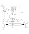
図1は、実施例1の車両用操舵装置が適用されたステア・バイ・ワイヤシステム(以下、「SBWシステム」という。)を示す全体構成図である。実施例1の車両用操舵装置は、(1)反力装置(操舵部)、(2)バックアップ装置、(3)転舵装置(転舵部)、(4)制御コントローラにより構成されている。以下、それぞれの構成を詳しく説明する。
First, the configuration will be described.
FIG. 1 is an overall configuration diagram showing a steer-by-wire system (hereinafter referred to as “SBW system”) to which the vehicle steering apparatus of the first embodiment is applied. The vehicle steering apparatus according to the first embodiment includes (1) a reaction force device (steering unit), (2) a backup device, (3) a steering device (steering unit), and (4) a control controller. Hereinafter, each configuration will be described in detail.
(1)反力装置
反力装置は、ハンドル(操作入力手段)1と、操舵角センサ2と、コラムシャフト3と、反力モータ(反力アクチュエータ)4と、反力モータ角センサ5と、を有して構成されている。
(1) Reaction force device The reaction force device comprises a handle (operation input means) 1, a
操舵角センサ2は、ハンドル1の回転角である操舵角を検出する。反力モータ4は、コラムシャフト3に路面反力等を模擬する操舵反力を付加する。反力モータ角センサ5は、反力モータ4の回転角を検出する。
The
(2)バックアップ装置
反力装置(1)と転舵装置(3)とを機械的に分離・連結することを可能とするバックアップ装置は、ケーブルコラム7とクラッチ6により構成されている。
(2) The backup device that can mechanically separate and connect the backup device reaction force device (1) and the steered device (3) includes a cable column 7 and a
ケーブルコラム7は、クラッチ6が締結されるバックアップモード時、反力装置(1)と転舵装置(3)との間に介在する部材との干渉を避けて迂回しながらも、トルクを伝達するコラムシャフト機能を発揮する機械式バックアップ機構である。ケーブルコラム7は、2つのリールに端部がリールに固定された2本のインナーケーブルを互いに逆方向へ巻き付け、2つのリールケースに2本のインナーケーブルを内挿したアウターチューブの両端を固定することにより構成されている。
In the backup mode in which the
クラッチ6は、コラムシャフト3とケーブルコラム7との間に介装され、実施例1では電磁クラッチを用いている。このクラッチ6は、締結されたとき、コラムシャフト3とピニオンシャフト8とが連結され、ハンドル1に加えられた操舵トルクは、ステアリング機構12に機械的に伝達される。
The
(3)転舵装置
転舵装置は、ピニオンシャフト8と、ホイールギア9と、転舵モータ(転舵アクチュエータ)10,10と、転舵モータ角センサ11,11と、ステアリング機構12と、ラック軸力センサ13,13と、操向輪14,14により構成されている。
(3) Steering device The steering device includes a
転舵モータ10,10は、ホイールギア9を介してピニオンシャフト8に転舵トルクを出力する。転舵モータ角センサ11,11は、転舵モータ10,10の回転角を検出する。ステアリング機構12は、ピニオンシャフト8の回転に応じて操向輪14,14を転舵する。ラック軸力センサ13,13は、ステアリング機構12に入力されるラック軸力を検出する。
The steered
(4)制御コントローラ
制御コントローラは、反力モータ4を駆動制御する反力コントローラ17と、転舵モータ10,10を駆動制御する転舵コントローラ18,18から構成され、双方向通信線19を介して情報交換可能に接続されている。
(4) Control Controller The control controller includes a
反力コントローラ17および転舵コントローラ18,18には、操舵角センサ2と、反力モータ角センサ5と、ラック軸力センサ13,13と、車速を検出する車速センサ15と、ヨーレートセンサ16と、からの検出値が入力される。
The
反力コントローラ17は、各センサ信号に基づいて、反力モータ指令角を設定し、反力モータ4を駆動制御する。転舵コントローラ18,18は、各センサ信号に基づいて、転舵モータ10,10の転舵モータ指令角を設定し、転舵モータ10,10を駆動制御する。
The
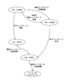
反力コントローラ17および転舵コントローラ18,18は、システムの状態をモニタリングし、システムが正常に作動している間は、SBWモード(クラッチ切り離しによるステア・バイ・ワイヤ制御)を維持し、反力モータ4または反力コントローラ17が失陥した場合には、バックアップモード(クラッチ締結による電動パワーステアリング制御)へ移行する(図2の2モータSBW→2モータEPS)。ここで、転舵モータ10,10および転舵コントローラ18,18を冗長系としているため、一方の転舵モータ10が失陥した場合でも、失陥していない方の転舵モータ10でSBW制御を継続することができる(図2の2モータSBW→1モータSBW)。なお、反力コントローラ17と2つの転舵コントローラ18,18が失陥した場合には、マニュアルステアリングモード(モータ制御無し)へ移行する。
The
次に、作用を説明する。
[反力モータ異常検出時の転舵制御処理]
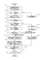
図3は、実施例1の転舵コントローラ18で実行される反力モータ異常検出時の転舵制御処理の流れを示すフローチャートで、以下、各ステップについて説明する。
Next, the operation will be described.
[Turning control processing when reaction force motor abnormality is detected]
FIG. 3 is a flowchart showing the flow of the turning control process performed when the reaction force motor abnormality is detected, which is executed by the
ステップS1では、正常制御時の転舵モータ指令角とバックアップモード移行時の転舵モータ指令角とのオフセット値を算出し、ステップS2へ移行する。実施例1では、バックアップモード移行時の転舵モータ指令角を、クラッチ6を締結してハンドル1と操向輪14,14とが機械的に連結された場合の、ステアリング機構12のメカギア比(ハンドル1の操舵角に対する操向輪14,14の転舵角の比)とする。
In step S1, an offset value between the steered motor command angle during normal control and the steered motor command angle during the backup mode transition is calculated, and the process proceeds to step S2. In the first embodiment, the steering motor command angle at the time of transition to the backup mode is determined based on the mechanical gear ratio of the
ステップS2では、反力モータ角センサ5の検出値や反力モータ4の実電流値等に基づき、反力モータ4の異常が検出されたか否かを判定する(反力アクチュエータ異常検出手段に相当)。YESの場合にはステップS3へ移行し、NOの場合にはステップS12へ移行する。
In step S2, it is determined whether or not an abnormality of the reaction force motor 4 has been detected based on the detection value of the reaction force
ステップS3では、転舵モータ指令角を異常検出時のものに保持し、ステップS4へ移行する。 In step S3, the steered motor command angle is held at the time of abnormality detection, and the process proceeds to step S4.
ステップS4では、クラッチ6に締結指令を出力し、ステップS5へ移行する。
In step S4, an engagement command is output to the
ステップS5では、反力モータ異常検出後、所定時間ΔTが経過したか否かを判定する。YESの場合にはステップS6へ移行し、NOの場合にはステップS13へ移行する。 In step S5, it is determined whether or not a predetermined time ΔT has elapsed after detecting the reaction force motor abnormality. If YES, the process proceeds to step S6, and if NO, the process proceeds to step S13.
ステップS6では、反力モータ異常を確定し、反力モータ電流を遮断してステップS7へ移行する。 In step S6, the reaction motor abnormality is confirmed, the reaction motor current is interrupted, and the process proceeds to step S7.
ステップS7では、操舵状態判断ロジックを実行する。具体的には、ハンドル1の操作方向と操向輪14,14の転舵方向とが逆相である場合にはステップS8へ移行する。保舵状態が所定時間ΔT経過したか、またはハンドル1の操作方向と操向輪14,14の転舵方向とが同相である場合にはステップS15へ移行する。
In step S7, a steering state determination logic is executed. Specifically, when the operation direction of the
ステップS8では、ハンドル1の操舵角とメカギア比を用いて転舵モータ指令角を算出し、ステップS9へ移行する。
In step S8, a steered motor command angle is calculated using the steering angle of the
ステップS9では、反力モータ4および反力コントローラ17の異常が確定した際のオフセット値を転舵モータ指令角に加算し、ステップS10へ移行する。
In step S9, the offset value when the abnormality of the reaction force motor 4 and the
ステップS10では、ステップS4でクラッチ締結指令を出力後、クラッチ締結に要する所定時間経過したか否かを判定する。YESの場合にはステップS11へ移行し、NOの場合にはステップS10を繰り返す。 In step S10, it is determined whether or not a predetermined time required for clutch engagement has elapsed after outputting the clutch engagement command in step S4. If YES, the process proceeds to step S11. If NO, step S10 is repeated.
ステップS11では、各モータをバックアップモードへ移行し、リターンへ移行する。 In step S11, each motor is shifted to the backup mode, and the flow is shifted to return.
ステップS12では、正常時のSBW制御を継続する。 In step S12, the normal SBW control is continued.
ステップS13では、クラッチ6にクラッチ解放指令を出力し、ステップS14へ移行する。
In step S13, a clutch release command is output to the
ステップS14では、正常時のSBW制御に復帰する。 In step S14, the normal SBW control is restored.
ステップS15では、転舵モータ指令角を、反力モータ異常確定時の転舵モータ指令角に保持し、ステップS10へ移行する。 In step S15, rolling the steering motor command angle, and held to the steering motor command angle when the reaction motor abnormality confirmation, the process proceeds to step S10.
[反力モータ異常検出時の転舵制御作動]
反力モータ4の異常発生時、ハンドル1の操作方向と操向輪14,14の転舵方向とが同相である場合には、図3のフローチャートにおいて、ステップS1→ステップS2→ステップS3→ステップS4→ステップS5→ステップS6→ステップS7→ステップS15→ステップS10→ステップS11へと進む流れとなる。よって、転舵角が、反力モータ異常確定時の転舵角に維持されるため、バックアップモードへ移行する過渡状態において、ドライバの操舵オーバーシュートおよびセルフアライニングトルクに起因するハンドル1と操向輪14,14との中立位置ずれを抑制でき、車両の軌跡がハンドル1に応じた走行ラインからずれるのを抑制できる。
[Turning control operation when reaction force motor abnormality is detected]
When an abnormality occurs in the reaction force motor 4, if the operation direction of the
反力モータ4の異常発生時、ハンドル1の操作方向と操向輪14,14の転舵方向とが逆相である場合には、図3のフローチャートにおいて、ステップS1→ステップS2→ステップS3→ステップS4→ステップS5→ステップS6→ステップS7→ステップS8→ステップS9→ステップS10→ステップS11へと進む流れとなる。よって、クラッチ6が完全に締結されるまでの一定時間、ハンドル1の操舵角に応じて操向輪14,14を転舵させる正常時制御と同様の制御を継続するため、操向輪14,14の変位量および車両の軌跡がハンドル1に応じた走行ラインからずれるのを最小限に抑えることができる。
When an abnormality occurs in the reaction force motor 4, if the operation direction of the
また、ハンドル1の操作方向と操向輪14,14の転舵方向とが逆相である場合には、ハンドル1の操舵角とメカギア比とから求まる転舵モータ指令角に応じて操向輪14,14が転舵される。すなわち、可変ギア比を正常時制御と同様に設定した場合、ハンドル1が操向輪14,14につられて大きく回転してしまうという問題が発生するが、可変ギア比を変化させることにより、ハンドル1が操向輪14,14につられることがなくなり、スムーズにバックアップモードへ移行することが可能となる。
Further, when the operation direction of the
[保舵状態での反力モータ故障]
一般的に、定常旋回時など、保舵状態で走行している際には、ドライバはハンドルに対し路面反力に釣り合うトルクを受動的にかけることにより、保舵状態を維持している。この状態で反力モータおよびその制御装置(反力コントローラ)の異常を検知し、反力モータ電流を遮断して反力モータの出力トルクがゼロになると、ハンドルは異常発生の直前にドライバがかけていたトルクにより、切り増し方向に動くことになる。これにより、ドライバの意図しない操舵オーバーシュートが発生する。
[Reaction force motor failure in steered state]
In general, when the vehicle is traveling in a steered state, such as during steady turning, the driver maintains the steered state by passively applying a torque that balances the road surface reaction force to the steering wheel. In this state, when an abnormality is detected in the reaction force motor and its control device (reaction force controller), the reaction force motor current is cut off and the output torque of the reaction force motor becomes zero. It will move in the direction of additional cutting by the torque. As a result, a steering overshoot unintended by the driver occurs.
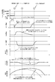
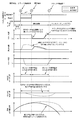
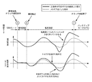
正常時の転舵制御に用いる操舵側の角度として、反力モータの回転角を用いている場合、反力モータが失陥した際には、反力モータの回転角を制御に用いることができない。図4において、時点Aでクラッチに締結指令を出力してから、時点Cでバックアップ装置のクラッチが完全に連結するまでの間、操向輪はセルフアライニングトルクにより直進方向に戻る。つまり、ドライバは保舵状態を維持しているにもかかわらず、操向輪はその意図に沿うように動作せず、ドライバに違和感を与える上、車両の軌跡が走行ラインから大きくずれてしまう。 When the rotation angle of the reaction force motor is used as the steering-side angle used for normal steering control, when the reaction force motor fails, the rotation angle of the reaction force motor cannot be used for control. . In FIG. 4, the steering wheel returns to the straight traveling direction by self-aligning torque from the time when the engagement command is output to the clutch at time A until the time when the clutch of the backup device is completely engaged. In other words, the steered wheels do not operate in accordance with the intention even though the driver maintains the steered state, giving the driver a sense of incongruity and greatly deviating from the travel line of the vehicle.
反力モータが失陥した際、操舵角または反力モータの回転角が使える場合には、転舵制御は、操舵角または反力モータの回転角に応じて転舵するため、意図しない操舵オーバーシュートにも応じて転舵されることとなり、車両はより大きく旋回してしまう。 If the steering angle or the rotation angle of the reaction force motor can be used when the reaction force motor fails, the steering control turns according to the steering angle or the rotation angle of the reaction force motor. The vehicle is steered according to the chute, and the vehicle turns more greatly.
[操舵状態での反力モータ故障]
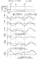
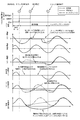
一方、図5に示すように、操舵角と転舵角との間に位相差が発生するような操舵を行っている状況(以下、操舵状態と呼ぶ)で走行している際に、反力モータおよびその制御装置に異常が発生すると、反力モータの発生するトルクがゼロになり、また、操向輪に関してはクラッチが完全に連結するまでの間はセルフアライニングトルクにより直進方向に戻される。つまり、操向輪はドライバの意図であるハンドル操作と連動すること無しに動作することになり、ドライバに違和感を与える上、車両の軌跡が走行ラインから大きくずれてしまう。すなわち、操舵状態においては、ドライバのハンドルを切った方向に操向輪を転舵させる制御を行う方が望ましい。
[Reaction force motor failure in steering state]
On the other hand, as shown in FIG. 5, when traveling in a situation where steering is performed such that a phase difference occurs between the steering angle and the turning angle (hereinafter referred to as a steering state), When an abnormality occurs in the motor and its control device, the torque generated by the reaction force motor becomes zero, and the steering wheel is returned to the straight traveling direction by the self-aligning torque until the clutch is completely connected. . That is, the steered wheel operates without being interlocked with the steering wheel operation intended by the driver, which gives the driver a sense of incongruity and causes the vehicle trajectory to deviate significantly from the travel line. That is, in the steering state, it is desirable to perform control to steer the steered wheels in the direction in which the driver's handle is turned.
[保舵状態での保持転舵制御作用]
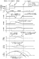
そこで、反力モータおよびその制御装置が何かしらの失陥をした場合、その制御装置により失陥を検知したと同時に転舵モータを現在の位置に保持する制御を行う(以下、保持転舵制御と呼ぶ)。これを実現する方法としては、例えば、図6のように、転舵モータ指令角を反力失陥時の値に固定する方法がある。この制御を行った場合、保舵状況で走行しているとき、反力モータの異常を検出し、バックアップモードへ移行する際、反力モータの発生トルクがゼロになるので、ハンドルが切り増し方向に動いてしまう(ハンドルを切っている方向と操向輪の向いている方向が同相)が、操向輪については、保持転舵制御を行うことによってハンドルの操作の如何にかかわらず、反力モータ異常検出時の転舵角に保持されるため、変位量は減少し、車両の軌跡も走行ラインからずれることがなくなる。
[Holding turning control action in the holding state]
Therefore, when the reaction force motor and its control device have some failure, the control device detects the failure and at the same time controls to hold the turning motor at the current position (hereinafter referred to as holding steering control). Call). As a method for realizing this, for example, as shown in FIG. 6, there is a method of fixing the steered motor command angle to a value at the time of reaction force failure. When this control is performed, when the vehicle is running in the steering-holding condition, the reaction force motor is detected to be abnormal, and the torque generated by the reaction force motor becomes zero when shifting to the backup mode. (The direction in which the steering wheel is turned and the direction in which the steering wheel is facing are in phase), but the steering wheel is controlled by holding steering control regardless of the operation of the steering wheel. Since the steering angle is maintained at the time when the motor abnormality is detected, the amount of displacement decreases, and the locus of the vehicle does not deviate from the travel line.
[操舵状態での保持転舵制御の問題]
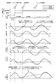
しかし、操舵状態で走行しているときには、操舵角と転舵角との間に位相差があるので、ハンドルを切っている方向と操向輪の向いている方向とが逆相となる状況が起こり得る。そういった状況下で反力モータの異常を検出し、バックアップモードへ移行する際、操向輪の保持転舵制御を行うと、ハンドルを切っている方向と車両の進む方向とが異なることとなり、走行ラインから車両の軌跡がずれてしまう。その上、ドライバの操舵意図が操向輪の転舵と連動していないため、違和感を与えることになる(図7)。
[Problem of holding steering control in steering state]
However, when traveling in a steering state, there is a phase difference between the steering angle and the steered angle, so there is a situation where the direction in which the steering wheel is turned and the direction in which the steered wheel is facing are in opposite phases. Can happen. Under such circumstances, when the abnormality of the reaction force motor is detected and the shift to the backup mode is performed, if the steering wheel holding steering control is performed, the direction in which the steering wheel is turned and the direction in which the vehicle travels will be different. The trajectory of the vehicle will deviate from the line. In addition, since the driver's steering intention is not linked to the steering of the steered wheels, a sense of incongruity is given (FIG. 7).
[操舵状態での連結時転舵制御作用]
この問題を解決するために、反力モータおよびその制御装置の異常を検出し、バックアップモードへ移行する際の過渡状態において、クラッチを締結する指令を出してから完全に締結するまでのある一定時間は、正常時制御と同様に、操舵角に応じた転舵角制御を継続する制御を行う(以下、連結時転舵制御と呼ぶ)。この連結時転舵制御を行うことによって、操舵状態で走行しているときに反力モータおよびその制御装置の異常を検出し、バックアップモードへ移行する際に、転舵モータはハンドルの操舵角に応じて転舵されるため(反力モータの回転角が使える場合は使っても良い。)、操向輪の変位量および車両の軌跡が走行ラインからずれるのを最小限に抑えることができる(図9)。
[Operation of turning control when connected in steering]
In order to solve this problem, a certain period of time from when a command to engage the clutch is issued until the clutch is completely engaged in a transient state when the reaction force motor and its control device are detected and transitioned to the backup mode. Performs control for continuing the steering angle control corresponding to the steering angle (hereinafter referred to as connected steering control), as in the normal control. By performing the steering control at the time of connection, the abnormality of the reaction force motor and its control device is detected when traveling in the steering state, and the steering motor is adjusted to the steering angle of the steering wheel when shifting to the backup mode. Since it is steered accordingly (may be used if the rotation angle of the reaction force motor can be used), it is possible to minimize the displacement of the steering wheel and the vehicle trajectory from deviating from the travel line ( FIG. 9).
[保舵状態での連結時転舵制御の問題]
ただし、連結時転舵制御を行った場合、保舵状態で走行しているときに反力モータおよびその制御装置の異常を検出し、バックアップモードへ移行する際に、ハンドルの切り増し分を操向輪の転舵角指令値として与えてしまうため、操向輪が内側へ切れ込み、結果車両の軌跡は内側へ巻き込んでしまう(図8)。
[Problems of steering control when connected in steered state]
However, when steering control is performed during connection, abnormalities in the reaction force motor and its control device are detected when the vehicle is running in the steering-holding state, and when the shift to the backup mode is performed, the steering wheel increment is manipulated. Since the steering wheel is given as the steering angle command value, the steered wheels are cut inward and as a result, the trajectory of the vehicle is caught inward (FIG. 8).
[保持転舵制御と転舵制御の切り替え作用]
これに対し、実施例1の車両用操舵装置では、上記保持転舵制御と連結時転舵制御とを切り替え、操向輪14,14を保持させた方が望ましい状況では保持転舵制御を行い、ドライバがハンドル1を切った方向に操向輪14,14を転舵させた方が望ましい状況では連結時転舵制御を行うようにする。これにより、各々の状況において操向輪14,14の変位量および車両の軌跡のずれを最小限に抑えることが可能となる。保持転舵制御を行っている場合の時系列に沿った車両挙動は、図6に示した通りである。また、連結時転舵制御を行っている場合の時系列に沿った車両挙動は、図9に示した通りである。
[Switching action between holding steering control and steering control]
On the other hand, in the vehicle steering apparatus of the first embodiment, the holding steering control is performed in a situation where it is desirable to switch between the holding steering control and the turning steering control and hold the steered
ここで、上記保持転舵制御と連結時転舵制御の切り替え条件に関して、例えば、操舵角速度を用い、ある一定値以下であれば保舵状態、逆にある一定値を超えると操舵状態と判断する方法、または操舵角速度に加えて、操舵トルク、転舵トルク(ラック軸力)を用い、ある一定値以下であれば保舵状態、それを上回れば操舵中と判断し、保舵状態、または操舵中かつ操舵トルクと転舵トルクが同相の場合は保持転舵制御を行い、操舵中で操舵トルクと転舵トルクが逆相となった場合は連結時転舵制御を行うといった方法がある。 Here, regarding the switching condition between the holding steering control and the connection-time steering control, for example, the steering angular velocity is used. If the steering angular velocity is below a certain value, the steering state is determined. In addition to the method or steering angular velocity, steering torque and steering torque (rack axial force) are used. If the torque is below a certain value, the steering state is determined. There is a method in which the holding steering control is performed when the steering torque and the turning torque are in phase, and when the steering torque and the turning torque are in the opposite phase during steering, the connection turning control is performed.
次に、効果を説明する。
実施例1の車両用操舵装置にあっては、以下に列挙する効果が得られる。
Next, the effect will be described.
In the vehicle steering apparatus according to the first embodiment, the following effects can be obtained.
(1) ハンドル1と反力モータ4を有する反力装置(1)と、操向輪14,14と転舵モータ10,10を有する転舵装置(3)と、ハンドル1から操向輪14,14に至る操舵系の途中に設けられ、正常時にハンドル1と操向輪14,14とを機械的に切り離し、異常時にハンドル1と操向輪14,14とを機械的に連結するクラッチ6と、正常時には、ハンドル1の操作量に応じて、反力モータ4と転舵モータ10,10の駆動制御を行う操舵制御手段(反力コントローラ17、転舵コントローラ18,18)と、を備えた車両用操舵装置において、反力モータ4の異常を検出する反力アクチュエータ異常検出手段(ステップS2)を備え、操舵制御手段は、反力アクチュエータ異常検出手段が異常検出してから異常と確定するまでの間、転舵モータ10,10への制御指令(転舵モータ指令角)を一定値に保持する保持転舵制御を実行し(ステップS15)、ハンドル1が所定の操舵状態のとき、保持転舵制御を中止し、操舵状態に応じた連結時転舵制御を実行する(ステップS9)。よって、各々の状況においてドライバの意図しない操舵オーバーシュート、操向輪14,14の変位量および車両の軌跡のずれを最小限に抑えることが可能となる。
(1) A reaction force device (1) having the
(2) 操舵制御手段は、ハンドル1の操作方向と操向輪14,14の転舵方向とが一致しないときには、連結時転舵制御を実行するため、ハンドル1と操向輪14,14とが逆相の場合に保持転舵制御を継続することで、操舵角と転舵角とのずれがより拡大するのを防止でき、操向輪14,14の変位量および車両の軌跡が走行ラインからずれるのを最小限に抑えることが可能となる。
(2) When the operation direction of the
(3) 操舵制御手段は、連結時転舵制御時、ハンドル1の操作量と、ハンドル1と操向輪14,14とが機械的に連結されたときのギア比(メカギア比)とに基づいて操向輪14,14を転舵する(ステップS8)。すなわち、バックアップモードへの移行時、クラッチ6は完全に繋がっていないものの、トルクの伝達は行われる。そのような状況下で可変ギア比を正常時制御と同じ値とした場合、ハンドル1が操向輪14,14につられて大きく回転してしまうという問題が発生するが、可変ギア比を変化させることより、ハンドル1が操向輪14,14につられることがなくなり、スムーズにバックアップモードへ移行することができる。
(3) The steering control means is based on the operation amount of the
実施例2は、連結時転舵制御では可変ギア比を反力モータ異常検出時よりも小さくする例である。なお、構成については図1に示した実施例1と同様であるため、説明を省略する。 The second embodiment is an example in which the variable gear ratio is made smaller in the turning control at the time of connection than when the reaction force motor abnormality is detected. The configuration is the same as that of the first embodiment shown in FIG.
次に、作用を説明する。
[反力モータ異常検出時の転舵制御処理]
図10は、実施例2の転舵コントローラ18で実行される反力モータ異常検出時の転舵制御処理の流れを示すフローチャートである。なお、図3に示した実施例1と同一処理を行うステップには、同一のステップ番号を付して説明を省略する。
Next, the operation will be described.
[Turning control processing when reaction force motor abnormality is detected]
FIG. 10 is a flowchart illustrating the flow of the turning control process when the reaction force motor abnormality is detected, which is executed by the turning
ステップS21では、ハンドル1の操舵角と減速した可変ギア比を用いて転舵モータ指令角を算出し、ステップS9へ移行する。すなわち、実施例2では、反力モータ4の異常発生時、ハンドル1の操作方向と操向輪14,14の転舵方向とが逆相である場合には、ハンドル1の操舵角と可変ギア比とから求まる転舵モータ指令角に応じて操向輪14,14が転舵され、このとき、可変ギア比は、反力モータ故障検出時よりも小さな値とし、時間の経過と共に徐々にメカギア比に近づける。
In step S21, a steered motor command angle is calculated using the steering angle of the
[連結時転舵制御における大可変ギア比の問題]
SBWシステムでは、ハンドルの操舵角に対する操向輪の転舵角の比であるギア比を可変にすることが可能である。例えば、低速域では可変ギア比は1対1よりも高いギア比とし、少量のハンドル操作で大舵角を切ることができるという特徴がある。しかし、連結時転舵制御を行う場合、通常時の可変ギア比を用いると問題が発生する。バックアップモードへ移行する過渡状態において、クラッチは完全には繋がっていないものの、トルクの伝達は行われる。この状況において、可変ギア比で増速された転舵角指令によって転舵モータが駆動されると、クラッチを介してハンドルを切り増し方向に大きく動かすことになる。これにより大きな転舵角指令が送られ、転舵モータが駆動され、ハンドルはより大きく回されることになる(図11)。
[Problem of large variable gear ratio in steering control when connected]
In the SBW system, the gear ratio, which is the ratio of the steered wheel turning angle to the steering wheel steering angle, can be made variable. For example, in the low speed range, the variable gear ratio is higher than 1: 1 and the large steering angle can be turned with a small amount of steering operation. However, when performing the turning control at the time of connection, a problem occurs if the variable gear ratio at the normal time is used. In the transition state to shift to the backup mode, torque is transmitted although the clutch is not completely engaged. In this situation, when the steered motor is driven by the steered angle command accelerated at the variable gear ratio, the steering wheel is turned through the clutch and moved greatly in the direction. As a result, a large steering angle command is sent, the steering motor is driven, and the steering wheel is rotated more (FIG. 11).
[ギア比可変作用]
実施例2では、バックアップモードへの移行状態においては、可変ギア比を変化させ、それをハンドル1の操舵角に乗じた値を転舵モータ指令角とする。ただし、この際の可変ギアの変化について、上記理由により反力モータ4およびその制御装置の異常検出時の値よりも小さな値とする。これにより、操舵状態におけるバックアップモード移行時、ハンドル1が大きく回されるという問題は解決される。
[Gear ratio variable action]
In the second embodiment, in the state of transition to the backup mode, the variable gear ratio is changed, and a value obtained by multiplying the variable gear ratio by the steering angle of the
また、バックアップモードに移行する際に可変ギア比を変化させるとき、転舵角をハンドル1と操向輪14,14とが機械的に連結されたときのメカギア比(ラック&ピニオンのギア比)の転舵角に近づけるように、可変ギア比で減速する。これにより、反力モータ4およびその制御装置の異常を検出した際の正常制御時の転舵モータ指令角から連結時転舵制御を行う際の転舵モータ指令角への値の急変は回避される(図12)。また、可変ギア比で減速するのみでも良い。
Also, when changing the variable gear ratio when shifting to the backup mode, the steering gear angle is the mechanical gear ratio when the
なお、補足として、正常時のSBWモード、バックアップEPSモード、SBWからバックアップモードへの移行時の3つの状態において、転舵側と操舵側の制御の状態を図12にまとめた。 As a supplement, FIG. 12 shows the control state of the steered side and the steering side in the three states at the time of transition from the normal SBW mode, the backup EPS mode, and the SBW to the backup mode.
次に、効果を説明する。
実施例2の車両用操舵装置にあっては、実施例1の効果(1),(2)に加え、以下に列挙する効果が得られる。
Next, the effect will be described.
In the vehicle steering apparatus of the second embodiment, the effects listed below are obtained in addition to the effects (1) and (2) of the first embodiment.
(4) 操舵制御手段は、連結時転舵制御時、ハンドル1の操作量に基づき、ハンドル1と操向輪14,14とのギア比を可変するため、ハンドル1が転舵角につられることがなく、スムーズにバックアップモードへ移行することができる。
(4) Since the steering control means varies the gear ratio between the
(5) 操舵制御手段は、連結時転舵制御時、ハンドル1と操向輪14,14とが機械的に連結されたときのギア比に対し、ハンドル1の操作量に対して操向輪14,14の転舵量が小さくなるようにギア比を可変するため、高速域では可変ギア比を減速される値に設定しているようなSBWシステムにおいて、バックアップモードでのギア比の方が高い場合、スムーズな移行を行うことができる。
(5) The steering control means is a steered wheel with respect to an operation amount of the
(6) 操舵制御手段は、連結時転舵制御時、ハンドル1の操作量と操向輪14,14の転舵量とが機械的に連結されているときの関係に近づけるようにギア比を可変するため、バックアップモード移行後のハンドル1と操向輪14,14の中立位置ずれを小さくできると共に、スムーズにバックアップモードへ移行することが可能となる。
(6) The steering control means adjusts the gear ratio so that the amount of operation of the
(他の実施例)
以上、本発明を実施するための最良の形態を、実施例1,2に基づいて説明したが、本発明の具体的な構成は、実施例1,2に限定されるものではなく、発明の要旨を逸脱しない範囲の設計変更等があっても本発明に含まれる。
(Other examples)
The best mode for carrying out the present invention has been described based on the first and second embodiments. However, the specific configuration of the present invention is not limited to the first and second embodiments. Design changes and the like within a range that does not depart from the gist are also included in the present invention.
1 ハンドル(操作入力手段)
2 操舵角センサ
3 コラムシャフト
4 反力モータ(反力アクチュエータ)
5 反力モータ角センサ
6 クラッチ
7 ケーブルコラム
8 ピニオンシャフト
9 ホイールギア
10,10 転舵モータ(転舵アクチュエータ)
11,11 転舵モータ角センサ
12 ステアリング機構
13,13 ラック軸力センサ
14,14 操向輪
15 車速センサ
16 ヨーレートセンサ
17 反力コントローラ
18,18 転舵コントローラ
19 双方向通信線
1 Handle (operation input means)
2 Steering angle sensor 3 Column shaft 4 Reaction force motor (reaction force actuator)
5 Reaction force
11, 11 Steering
Claims (7)
操向輪と転舵アクチュエータを有する転舵部と、
前記操作入力手段から前記操向輪に至る操舵系の途中に設けられ、正常時に前記操作入力手段と前記操向輪とを機械的に切り離し、異常時に前記操作入力手段と前記操向輪とを機械的に連結するクラッチと、
正常時には、前記操作入力手段の操作量に応じて、前記反力アクチュエータと前記転舵アクチュエータの駆動制御を行う操舵制御手段と、
を備えた車両用操舵装置において、
前記反力アクチュエータの異常を検出する反力アクチュエータ異常検出手段を備え、
前記操舵制御手段は、
前記反力アクチュエータの異常が検出されてから少なくとも異常と確定するまでの間、前記転舵アクチュエータへの制御指令を一定値に保持する保持転舵制御を実行し、
前記反力アクチュエータの異常と確定した場合、前記操作入力手段の操作方向と前記操向輪の転舵方向とが一致しないときは、前記保持転舵制御を中止し、前記クラッチにより前記操作入力手段と前記操向輪とが機械的に連結されるまでの間、前記操作入力手段の操作量に基づき前記転舵アクチュエータを駆動制御して前記操向輪を転舵する連結時転舵制御を実行する
ことを特徴とする車両用操舵装置。 A steering unit having an operation input means and a reaction force actuator;
A steered portion having a steered wheel and a steered actuator;
Provided in the middle of the operation input unit of the steering system leading to the steering wheel, mechanically disconnected with said operation input means during normal and the steering wheel, and the operation input unit at the time of abnormality and the steering wheel A clutch that mechanically connects the
Steering control means for performing drive control of the reaction force actuator and the steered actuator according to the operation amount of the operation input means at normal time;
In a vehicle steering apparatus comprising:
Reaction force actuator abnormality detection means for detecting abnormality of the reaction force actuator,
The steering control means includes
From the time when the abnormality of the reaction force actuator is detected to the time when it is determined that the abnormality is at least , the holding steering control for holding the control command to the steering actuator at a constant value is executed,
When it is determined that the reaction force actuator is abnormal, if the operation direction of the operation input means does not coincide with the steering direction of the steered wheels , the holding steering control is stopped and the operation input means is operated by the clutch. Until the steering wheel is mechanically connected to the steering wheel, the steering control is performed when the steering wheel is steered by driving the steering actuator based on the operation amount of the operation input means. A vehicle steering apparatus.
前記操舵制御手段は、前記反力アクチュエータの異常と確定した場合、前記操作入力手段の操作方向と前記操向輪の転舵方向とが逆相であるとき、前記連結時転舵制御を実行することを特徴とする車両用操舵装置。 The vehicle steering apparatus according to claim 1,
Said steering control unit, the case where the determined the abnormality of the reaction force actuator, when the steering direction of the operation direction of the operation input means and said steering wheel are opposite phase, perform the connection time turning control A vehicle steering apparatus.
前記操舵制御手段は、前記連結時転舵制御時、前記操作入力手段の操作量と、前記操作入力手段と前記操向輪とが機械的に連結されたときのギア比とに基づいて前記操向輪を転舵することを特徴とする車両用操舵装置。 The vehicle steering apparatus according to claim 1 or 2,
The steering control unit is configured to control the operation based on an operation amount of the operation input unit and a gear ratio when the operation input unit and the steered wheel are mechanically connected during the steering control at the time of connection. A steering apparatus for a vehicle, wherein the steering wheel is steered.
前記操舵制御手段は、前記連結時転舵制御時、前記操作入力手段の操作量に基づき、前記操作入力手段と前記操向輪とのギア比を可変することを特徴とする車両用操舵装置。 The vehicle steering apparatus according to claim 1 or 2,
The vehicle steering apparatus according to claim 1, wherein the steering control unit varies a gear ratio between the operation input unit and the steered wheel based on an operation amount of the operation input unit during the turning control at the time of connection.
前記操舵制御手段は、前記連結時転舵制御時、前記操作入力手段と前記操向輪とが機械的に連結されたときのギア比に対し、前記操作入力手段の操作量に対して前記操向輪の転舵量が小さくなるようにギア比を可変することを特徴とする車両用操舵装置。 The vehicle steering device according to claim 4,
The steering control unit is configured to control the operation amount of the operation input unit with respect to a gear ratio when the operation input unit and the steered wheel are mechanically connected during the steering control. A vehicle steering apparatus, wherein a gear ratio is varied so that a steering amount of a facing wheel is reduced.
前記操舵制御手段は、前記連結時転舵制御時、前記操作入力手段の操作量と前記操向輪の転舵量とが機械的に連結されているときの関係に近づけるようにギア比を可変することを特徴とする車両用操舵装置。 In the vehicle steering apparatus according to claim 4 or 5,
The steering control means varies the gear ratio so as to approximate the relationship between the operation amount of the operation input means and the steered amount of the steered wheel during the steering control at the time of connection. A vehicle steering apparatus.
操向輪と転舵アクチュエータを有する転舵部と、
前記操作入力手段から前記操向輪に至る操舵系の途中に設けられ、正常時に前記操作入力手段と前記操向輪とを機械的に切り離し、異常時に前記操作入力手段と前記操向輪とを機械的に連結するクラッチと、
正常時には、前記操作入力手段の操作量に応じて、前記反力アクチュエータと前記転舵アクチュエータの駆動制御を行う操舵制御手段と、
を備えた車両用操舵装置において、
前記反力アクチュエータの異常を検出してから少なくとも異常と確定するまでの間、前記転舵アクチュエータへの制御指令を一定値に保持する保持転舵制御を実行し、
前記反力アクチュエータの異常と確定した場合、前記操作入力手段の操作方向と前記操向輪の転舵方向とが一致しないときは、前記保持転舵制御を中止し、前記クラッチにより前記操作入力手段と前記操向輪とが機械的に連結されるまでの間、前記操作入力手段の操作量に基づき前記操向輪を転舵する連結時転舵制御を実行する
ことを特徴とする車両用操舵装置。 A steering unit having an operation input means and a reaction force actuator;
A steered portion having a steered wheel and a steered actuator;
Provided in the middle of the operation input unit of the steering system leading to the steering wheel, mechanically disconnected with said operation input means during normal and the steering wheel, and the operation input unit at the time of abnormality and the steering wheel A clutch that mechanically connects the
Steering control means for performing drive control of the reaction force actuator and the steered actuator according to the operation amount of the operation input means at normal time;
In a vehicle steering apparatus comprising:
From the time when the abnormality of the reaction force actuator is detected to the time when it is determined that the abnormality is at least, holding steering control for holding a control command to the steering actuator at a constant value is executed,
When it is determined that the reaction force actuator is abnormal, if the operation direction of the operation input means does not coincide with the steering direction of the steered wheels , the holding steering control is stopped and the operation input means is operated by the clutch. Vehicle steering, wherein steering control is performed to steer the steering wheel based on an operation amount of the operation input means until the steering wheel is mechanically connected to the steering wheel. apparatus.
Priority Applications (1)
| Application Number | Priority Date | Filing Date | Title |
|---|---|---|---|
| JP2005156236A JP4635720B2 (en) | 2005-05-27 | 2005-05-27 | Vehicle steering system |
Applications Claiming Priority (1)
| Application Number | Priority Date | Filing Date | Title |
|---|---|---|---|
| JP2005156236A JP4635720B2 (en) | 2005-05-27 | 2005-05-27 | Vehicle steering system |
Publications (2)
| Publication Number | Publication Date |
|---|---|
| JP2006327503A JP2006327503A (en) | 2006-12-07 |
| JP4635720B2 true JP4635720B2 (en) | 2011-02-23 |
Family
ID=37549638
Family Applications (1)
| Application Number | Title | Priority Date | Filing Date |
|---|---|---|---|
| JP2005156236A Expired - Fee Related JP4635720B2 (en) | 2005-05-27 | 2005-05-27 | Vehicle steering system |
Country Status (1)
| Country | Link |
|---|---|
| JP (1) | JP4635720B2 (en) |
Families Citing this family (3)
| Publication number | Priority date | Publication date | Assignee | Title |
|---|---|---|---|---|
| JP5239245B2 (en) * | 2007-07-27 | 2013-07-17 | 日産自動車株式会社 | Vehicle steering control device |
| JP5310088B2 (en) * | 2009-02-26 | 2013-10-09 | 日産自動車株式会社 | Vehicle steering device, vehicle steering method, and vehicle with vehicle steering device |
| JP6533772B2 (en) | 2016-11-29 | 2019-06-19 | 本田技研工業株式会社 | Steering device |
Family Cites Families (3)
| Publication number | Priority date | Publication date | Assignee | Title |
|---|---|---|---|---|
| JP2001301639A (en) * | 2000-04-24 | 2001-10-31 | Nissan Motor Co Ltd | Vehicle steering system |
| JP4114481B2 (en) * | 2003-01-07 | 2008-07-09 | 日産自動車株式会社 | Vehicle steering control device |
| JP2005096745A (en) * | 2003-08-28 | 2005-04-14 | Nissan Motor Co Ltd | Vehicle steering system |
-
2005
- 2005-05-27 JP JP2005156236A patent/JP4635720B2/en not_active Expired - Fee Related
Also Published As
| Publication number | Publication date |
|---|---|
| JP2006327503A (en) | 2006-12-07 |
Similar Documents
| Publication | Publication Date | Title |
|---|---|---|
| JP5804198B2 (en) | Vehicle steering control apparatus and steering control method | |
| US7664584B2 (en) | Steering control system | |
| EP1205371B1 (en) | Motor vehicle steering system | |
| EP1939069B1 (en) | Vehicle Steering Device and Control Method for Vehicle Steering Device | |
| EP1726511B1 (en) | Steering control | |
| JP4853053B2 (en) | Vehicle steering control device | |
| JP4884056B2 (en) | Vehicle steering control device | |
| US20160159388A1 (en) | Steering system for vehicle | |
| JP2017210213A (en) | Vehicular steering apparatus | |
| JP2005096745A (en) | Vehicle steering system | |
| JP4506509B2 (en) | Steering control device | |
| JP5239245B2 (en) | Vehicle steering control device | |
| JP5412822B2 (en) | Vehicle steering control device | |
| JP5076564B2 (en) | Drive control device and steering control device using the same | |
| JP4635720B2 (en) | Vehicle steering system | |
| JP6140091B2 (en) | Vehicle steering system | |
| JP2017001611A (en) | Steering control device | |
| JP7270463B2 (en) | vehicle steering device | |
| JP2006044378A (en) | Vehicle steering system | |
| JP4517902B2 (en) | Steering control device | |
| JP2004090783A (en) | Vehicle steering system | |
| JP4243146B2 (en) | Battery state determination device in electric steering device | |
| JP2005254982A (en) | Variable steering angle device for vehicles | |
| JP4436272B2 (en) | Vehicle steering system | |
| JP4379250B2 (en) | Vehicle steering system |
Legal Events
| Date | Code | Title | Description |
|---|---|---|---|
| A621 | Written request for application examination |
Free format text: JAPANESE INTERMEDIATE CODE: A621 Effective date: 20080325 |
|
| A131 | Notification of reasons for refusal |
Free format text: JAPANESE INTERMEDIATE CODE: A131 Effective date: 20100713 |
|
| A977 | Report on retrieval |
Free format text: JAPANESE INTERMEDIATE CODE: A971007 Effective date: 20100715 |
|
| A521 | Request for written amendment filed |
Free format text: JAPANESE INTERMEDIATE CODE: A523 Effective date: 20100803 |
|
| TRDD | Decision of grant or rejection written | ||
| A01 | Written decision to grant a patent or to grant a registration (utility model) |
Free format text: JAPANESE INTERMEDIATE CODE: A01 Effective date: 20101026 |
|
| A01 | Written decision to grant a patent or to grant a registration (utility model) |
Free format text: JAPANESE INTERMEDIATE CODE: A01 |
|
| A61 | First payment of annual fees (during grant procedure) |
Free format text: JAPANESE INTERMEDIATE CODE: A61 Effective date: 20101108 |
|
| FPAY | Renewal fee payment (event date is renewal date of database) |
Free format text: PAYMENT UNTIL: 20131203 Year of fee payment: 3 |
|
| R150 | Certificate of patent or registration of utility model |
Ref document number: 4635720 Country of ref document: JP Free format text: JAPANESE INTERMEDIATE CODE: R150 Free format text: JAPANESE INTERMEDIATE CODE: R150 |
|
| LAPS | Cancellation because of no payment of annual fees |