JP4635663B2 - Image processing system, image processing apparatus and method, recording medium, and program - Google Patents
Image processing system, image processing apparatus and method, recording medium, and program Download PDFInfo
- Publication number
- JP4635663B2 JP4635663B2 JP2005073752A JP2005073752A JP4635663B2 JP 4635663 B2 JP4635663 B2 JP 4635663B2 JP 2005073752 A JP2005073752 A JP 2005073752A JP 2005073752 A JP2005073752 A JP 2005073752A JP 4635663 B2 JP4635663 B2 JP 4635663B2
- Authority
- JP
- Japan
- Prior art keywords
- difference
- value
- subject
- image
- data
- Prior art date
- Legal status (The legal status is an assumption and is not a legal conclusion. Google has not performed a legal analysis and makes no representation as to the accuracy of the status listed.)
- Expired - Fee Related
Links
Images


Landscapes
- Closed-Circuit Television Systems (AREA)
- Studio Devices (AREA)
- Image Analysis (AREA)
- Image Processing (AREA)
Description
本発明は、画像処理システム、画像処理装置および方法、記録媒体、並びにプログラムに関し、特に、被写体の動きを検出する画像処理システム、画像処理装置および方法、記録媒体、並びにプログラムに関する。 The present invention relates to an image processing system, an image processing apparatus and method, a recording medium, and a program, and more particularly to an image processing system, an image processing apparatus and method, a recording medium, and a program for detecting the motion of a subject.
従来、ボタンやスイッチなどを操作せずに、画像認識の技術を用いてユーザの身体の動きや形を認識して、ユーザの身振りや手振りなどにより各種の装置の操作を行うインタフェース(以下、ジェスチャインタフェースと称する)の研究が行われている。例えば、車載用のナビゲーションシステムにジェスチャインタフェースを用いて、手を動かした方向に画面がスクロールしたり、指で示した数の項目が選択されるようにしたりすれば、運転中でも、簡単かつ安全にナビゲーションシステムを操作することができるようになる。 Conventionally, an interface (hereinafter referred to as a gesture) that recognizes the movement and shape of a user's body using image recognition technology without operating buttons or switches, and operates various devices by user's gestures or hand gestures. (Referred to as the interface). For example, if you use a gesture interface in an in-vehicle navigation system and scroll the screen in the direction you move your hand or select the number of items indicated by your finger, you can easily and safely even while driving. The navigation system can be operated.
ところで、ジェスチャインタフェースを実現するには、被写体の動きを正確に検出する技術が重要である。 By the way, in order to realize a gesture interface, a technique for accurately detecting the movement of a subject is important.
被写体の動きを検出する手法には、フレーム間の画像の差分をとり、フレーム間の違いを検出することにより、被写体の動きを検出する方法(以下、差分検出方法と称する)がある(例えば、特許文献1参照)。 As a method for detecting the motion of the subject, there is a method of detecting the motion of the subject by taking a difference between images between frames and detecting a difference between frames (hereinafter referred to as a difference detection method) (for example, Patent Document 1).
また、画像内の被写体の輪郭を抽出して、被写体の動きを検出する方法(以下、輪郭検出方法と称する)がある。例えば、輪郭検出方法では、例えば、まず、画像内の画素値が急激に変化する部分などから被写体の輪郭を抽出する。次に、物体形状認識の手法を用いて、予め登録されている検出対象物(例えば、ユーザの手)の特徴量に基づいて、抽出した輪郭の中から検出対象物の輪郭を検出する。そして、複数のフレーム間の検出対象物の位置や形状の変化などに基づいて、検出対象物の動きを検出する。 Further, there is a method for extracting the contour of a subject in an image and detecting the motion of the subject (hereinafter referred to as a contour detection method). For example, in the contour detection method, for example, first, the contour of the subject is extracted from a portion where the pixel value in the image changes rapidly. Next, the contour of the detection target is detected from the extracted contours based on the feature amount of the detection target (for example, the user's hand) registered in advance using the object shape recognition technique. Then, the movement of the detection target is detected based on a change in the position and shape of the detection target between a plurality of frames.
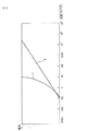
図1は、従来の撮像装置に使用されるCCD(Charge Coupled Device)撮像素子の感度特性を示すグラフである。図1の横軸は、入射光の照度(単位は、ルクス(lux))の対数値を示し、縦軸は入射光の照度に対する感度を示している。線1はCCD撮像素子の感度特性を示し、線2は人の目の感度特性を示している。なお、従来のCMOS(Complementary Metal Oxide Semiconductor)撮像素子の感度特性は、線1に示されるCCD撮像素子の感度特性とほぼ類似したものとなる。
FIG. 1 is a graph showing sensitivity characteristics of a CCD (Charge Coupled Device) image pickup element used in a conventional image pickup apparatus. The horizontal axis in FIG. 1 indicates the logarithmic value of the illuminance (unit is lux) of the incident light, and the vertical axis indicates the sensitivity to the illuminance of the incident light.
図1に示されるように、CCD撮像素子は、人の目よりダイナミックレンジが狭い。従って、CCD撮像素子を用いた撮像装置では、入射光の照度がCCD撮像素子のダイナミックレンジ内に収まるように、絞りやシャッタースピードなどを調整する必要がある。 As shown in FIG. 1, the CCD imaging device has a narrower dynamic range than the human eye. Therefore, in an image pickup apparatus using a CCD image pickup device, it is necessary to adjust an aperture, a shutter speed, and the like so that the illuminance of incident light is within the dynamic range of the CCD image pickup device.
しかしながら、被写体の光の照度の範囲がCCD撮像素子のダイナミックレンジを超える場合、被写体の明るい領域の画素の画素値がCCD撮像素子が出力可能な画素値の最大値に制限されたり、被写体の暗い領域の画素の画素値がCCD撮像素子が出力可能な画素値の最小値に制限されたりする輝度クリッピングが発生する。また、入射光量を調整した場合、例えば、被写体の輝度が変動しない領域に対応する入射光量が変動し、その領域の画素値が変動するなど、入射光量の調整に伴う画素値の変動が発生する。すなわち、従来のCCD撮像素子を用いた撮像装置では、被写体の輝度の変動および被写体の動き以外の要因により画素値が変動する。 However, when the illuminance range of the subject light exceeds the dynamic range of the CCD image sensor, the pixel value of the pixel in the bright area of the subject is limited to the maximum pixel value that can be output by the CCD image sensor, or the subject is dark Luminance clipping occurs in which the pixel value of the pixel in the region is limited to the minimum pixel value that can be output by the CCD image sensor. In addition, when the incident light amount is adjusted, for example, the incident light amount corresponding to a region where the luminance of the subject does not fluctuate fluctuates, and the pixel value of the region fluctuates. . That is, in an imaging apparatus using a conventional CCD imaging device, the pixel value varies due to factors other than the variation in luminance of the subject and the movement of the subject.
従って、被写体の動きを正確に検出するためには、被写体の輝度の変動および被写体の動きによる画素値の変動と、それ以外の要因による画素値の変動を区分する必要がある。そのため、差分検出方法においても、例えば、その被写体の画像の輪郭を強調する輪郭強調処理などを行う必要があり、処理が複雑になってしまう。また、周囲の明るさが大きく変化したり、被写体の輝度の範囲が広い場合には、被写体の輝度の変動および被写体の動きによる画素値の変動と、それ以外の要因による画素値の変動を区分することが困難であり、被写体の動きを正確に検出できない場合がある。 Therefore, in order to accurately detect the movement of the subject, it is necessary to distinguish the fluctuation of the luminance of the subject and the fluctuation of the pixel value due to the movement of the subject from the fluctuation of the pixel value due to other factors. Therefore, also in the difference detection method, for example, it is necessary to perform contour enhancement processing for enhancing the contour of the image of the subject, and the processing becomes complicated. Also, if the surrounding brightness changes significantly or the subject brightness range is wide, the pixel value variation due to subject brightness variation and subject movement is separated from the pixel value variation due to other factors. In some cases, it is difficult to accurately detect the movement of the subject.
また、輪郭検出方法では、上述したように輪郭抽出処理、検出対象物の検出処理、および、動き検出処理など複雑な処理を行う必要がある。さらに、輪郭検出方法では、周囲の明るさなどの撮像条件の変動、物体の重なり、物体の向きや変形などを考慮する必要があり、被写体の動きを正確に検出することが困難である。また、輪郭抽出処理はノイズの影響を受けやすく、被写体の動きを正確に検出することが困難である。 Further, in the contour detection method, as described above, it is necessary to perform complicated processing such as contour extraction processing, detection target detection processing, and motion detection processing. Furthermore, in the contour detection method, it is necessary to consider fluctuations in imaging conditions such as ambient brightness, object overlap, object orientation and deformation, and it is difficult to accurately detect the movement of the subject. Further, the contour extraction process is easily affected by noise, and it is difficult to accurately detect the movement of the subject.
本発明は、このような状況に鑑みてなされたものであり、より簡単かつ正確に被写体の動きを検出するようにするものである。 The present invention has been made in view of such a situation, and is intended to detect the movement of a subject more easily and accurately.
本発明の画像処理システムは、被写体を撮像し、入射光量の対数にほぼ比例した画素値からなる画像データを出力する撮像装置と、撮像装置から出力された画像データの第1のフレームの各画素値と第2のフレームの各画素値との差分である差分値からなる差分データを生成する差分データ生成手段と、差分データにおける差分値の絶対値の度数分布において、画素数が極小となる階級のうち差分値の絶対値の範囲が最小の階級の範囲内の差分値の絶対値を変動閾値に設定する閾値設定手段と、差分データにおいて差分値の絶対値が変動閾値以上の画素からなる抽出領域内の被写体の輪郭に基づいて、被写体の動きを検出する動き検出手段とを含むことを特徴とする。 An image processing system of the present invention captures an image of a subject and outputs image data composed of pixel values substantially proportional to the logarithm of the amount of incident light, and each pixel of a first frame of image data output from the imaging device. a difference data generating means for generating values and the difference data formed of the difference value is a difference between each pixel value of the second frame, Oite the frequency distribution of the absolute value of the difference value in the difference data, the number of pixels and a minimum The threshold value setting means for setting the absolute value of the difference value in the range of the class having the smallest absolute value range of the difference value as the fluctuation threshold value, and the pixels in which the absolute value of the difference value in the difference data is not less than the fluctuation threshold value And a motion detection means for detecting the motion of the subject based on the contour of the subject in the extraction area .
撮像装置は、例えば、HDRC(High Dynamic Range CMOS(Complementary Metal Oxide Semiconductor))などの対数変換型撮像素子を用い、人の目より広いダイナミックレンジで被写体を撮像できる撮像装置により構成される。 The imaging device is configured by an imaging device that uses a logarithmic conversion type imaging device such as HDRC (High Dynamic Range CMOS (Complementary Metal Oxide Semiconductor)) and can capture a subject with a dynamic range wider than the human eye.
差分データ生成手段、閾値設定手段、および、動き検出手段は、例えば、CPU(Central Processing Unit)、DSP(Digital Signal Processor)などの演算装置により構成される。 The difference data generation means, threshold setting means, and motion detection means are constituted by arithmetic devices such as a CPU (Central Processing Unit) and a DSP (Digital Signal Processor), for example.
差分データは、例えば、2枚のフレーム間の画像データの同じ位置にある画素間の差分をとることにより生成される。また、差分値は、例えば、差分データの各画素の画素値とされる。 The difference data is generated, for example, by taking a difference between pixels at the same position of image data between two frames. The difference value is, for example, the pixel value of each pixel of the difference data.
本発明の画像処理システムにおいては、被写体が撮像され、入射光量の対数にほぼ比例した画素値からなる画像データが出力され、出力された画像データの第1のフレームの各画素値と第2のフレームの各画素値との差分である差分値からなる差分データが生成され、差分データにおける差分値の絶対値の度数分布において、画素数が極小となる階級のうち差分値の絶対値の範囲が最小の階級の範囲内の差分値の絶対値が変動閾値に設定され、差分データにおいて差分値の絶対値が変動閾値以上の画素からなる抽出領域内の被写体の輪郭に基づいて、被写体の動きが検出される。 In the image processing system of the present invention, a subject is imaged, image data composed of pixel values approximately proportional to the logarithm of the incident light quantity is output, and each pixel value of the first frame of the output image data and the second image data are output. differential data consisting of the difference value is a difference between each pixel value of the frame is generated, Oite the frequency distribution of the absolute value of the difference value in the difference data, the number of pixels is an absolute value of the difference value of the class consisting of a minimum The absolute value of the difference value in the range of the class having the smallest range is set as the variation threshold, and based on the contour of the subject in the extraction area composed of pixels in which the absolute value of the difference value is greater than or equal to the variation threshold in the difference data , Motion is detected.
従って、被写体の動きを簡単かつ確実に検出することができる。これにより、動き検出を行う画像処理装置や半導体チップなどを小型化、低消費電力化、および、低価格化することができる。 Therefore, the movement of the subject can be detected easily and reliably. As a result, it is possible to reduce the size, the power consumption, and the price of an image processing device or a semiconductor chip that performs motion detection.
本発明の画像処理装置は、被写体を撮像した画像の画像データであって、入射光量の対数にほぼ比例した画素値からなる画像データの第1のフレームの各画素値と第2のフレームの各画素値との差分である差分値からなる差分データを生成する差分データ生成手段と、差分データにおける差分値の絶対値の度数分布において、画素数が極小となる階級のうち差分値の絶対値が最小の階級の範囲内の差分値の絶対値を変動閾値に設定する閾値設定手段と、差分データにおいて差分値の絶対値が変動閾値以上の画素からなる抽出領域内の被写体の輪郭に基づいて、被写体の動きを検出する動き検出手段とを含むことを特徴とする。 The image processing apparatus of the present invention is image data of an image obtained by capturing an image of a subject, and each pixel value of the first frame and each of the second frame of the image data composed of pixel values substantially proportional to the logarithm of the incident light quantity. a difference data generating means for generating differential data comprising a difference value that is the difference between pixel values, Oite the frequency distribution of the absolute value of the difference value in the difference data, an absolute difference value among the classes in which the number of pixels is minimum Based on the threshold setting means for setting the absolute value of the difference value within the range of the smallest value as the variation threshold, and the contour of the subject in the extraction area composed of pixels in which the absolute value of the difference value is equal to or greater than the variation threshold in the difference data And motion detection means for detecting the motion of the subject.
差分データ生成手段、閾値設定手段、および、動き検出手段は、例えば、CPU(Central Processing Unit)、DSP(Digital Signal Processor)などの演算装置により構成される。 The difference data generation means, threshold setting means, and motion detection means are constituted by arithmetic devices such as a CPU (Central Processing Unit) and a DSP (Digital Signal Processor), for example.
差分データは、例えば、2枚のフレーム間の画像データの同じ位置にある画素間の差分をとることにより生成される。また、差分値は、例えば、差分データの各画素の画素値とされる。 The difference data is generated, for example, by taking a difference between pixels at the same position of image data between two frames. The difference value is, for example, the pixel value of each pixel of the difference data.
本発明の画像処理装置においては、被写体を撮像した画像の画像データであって、入射光量の対数にほぼ比例した画素値からなる画像データの第1のフレームの各画素値と第2のフレームの各画素値との差分である差分値からなる差分データが生成され、差分データにおける差分値の絶対値の度数分布において、画素数が極小となる階級のうち差分値の絶対値が最小の階級の範囲内の差分値の絶対値が変動閾値に設定され、差分データにおいて差分値の絶対値が変動閾値以上の画素からなる抽出領域内の被写体の輪郭に基づいて、被写体の動きが検出される In the image processing apparatus of the present invention, image data of an image obtained by capturing an image of a subject, each pixel value of the first frame of the image data having pixel values substantially proportional to the logarithm of the incident light amount, and the second frame. differential data consisting of the difference value is a difference between each pixel value is generated, Oite the frequency distribution of the absolute value of the difference value in the difference data, the absolute value of the difference values among the classes in which the number of pixels becomes minimum is the minimum The absolute value of the difference value within the class range is set as the fluctuation threshold, and the movement of the subject is detected based on the contour of the subject in the extraction area composed of pixels in which the absolute value of the difference value is greater than or equal to the fluctuation threshold in the difference data . Ru
従って、被写体の動きを簡単かつ確実に検出することができる。これにより、動き検出を行う画像処理装置や半導体チップなどを小型化、低消費電力化、および、低価格化することができる。 Therefore, the movement of the subject can be detected easily and reliably. As a result, it is possible to reduce the size, the power consumption, and the price of an image processing device or a semiconductor chip that performs motion detection.
本発明の画像処理装置においては、動き検出手段は、抽出領域内において、被写体の輪郭を抽出し、被写体の移動方向の輪郭の幅に基づいて、被写体の動きベクトルの大きさを求め、差分データにおける差分値の位置の分布に基づいて、被写体の動きベクトルの方向を求めるようにすることができる。 In the image processing apparatus of the present invention, the motion detection means extracts the contour of the subject in the extraction region, obtains the size of the motion vector of the subject based on the width of the contour in the movement direction of the subject, and calculates the difference data The direction of the motion vector of the subject can be obtained based on the distribution of the difference value positions at.
本発明の画像処理装置においては、画像データは、半導体のサブスレッショルド特性を利用して、入射光量の対数にほぼ比例した画素値を出力する対数変換型の撮像素子を有する撮像装置により出力されるようにすることができる。 In the image processing apparatus of the present invention, the image data is output by an imaging apparatus having a logarithmic conversion type imaging element that outputs a pixel value substantially proportional to the logarithm of the incident light amount by utilizing a semiconductor sub-threshold characteristic. Can be.
従って、周囲の明るさが大きく変動する環境下においても、被写体の動きを確実に検出することができる。また、被写体の輝度などに応じて、入射光量を調整する必要がないため、動き検出処理に要する時間を短縮することができる。 Therefore, it is possible to reliably detect the movement of the subject even in an environment where the brightness of the surroundings greatly fluctuates. Further, since it is not necessary to adjust the amount of incident light according to the luminance of the subject, the time required for the motion detection process can be shortened.
本発明の画像処理装置においては、撮像素子は、HDRC(High Dynamic Range CMOS(Complementary Metal Oxide Semiconductor))であるようにすることができる。 In the image processing apparatus of the present invention, the image sensor can be an HDRC (High Dynamic Range CMOS (Complementary Metal Oxide Semiconductor)).
従って、周囲の明るさが大きく変動する環境下においても、被写体の動きを確実に検出することができる。また、被写体の輝度などに応じて、入射光量を調整する必要がないため、動き検出処理に要する時間を短縮することができる。 Therefore, it is possible to reliably detect the movement of the subject even in an environment where the brightness of the surroundings greatly fluctuates. Further, since it is not necessary to adjust the amount of incident light according to the luminance of the subject, the time required for the motion detection process can be shortened.
本発明の画像処理方法およびプログラムは、被写体を撮像した画像の画像データであって、入射光量の対数にほぼ比例した画素値からなる画像データの第1のフレームの各画素値と第2のフレームの各画素値との差分である差分値からなる差分データを生成する差分データ生成ステップと、差分データにおける差分値の絶対値の度数分布において、画素数が極小となる階級のうち差分値の絶対値が最小の階級の範囲内の差分値の絶対値を変動閾値に設定する閾値設定ステップと、差分データにおいて差分値の絶対値が変動閾値以上の画素からなる抽出領域内の被写体の輪郭に基づいて、被写体の動きを検出する動き検出ステップとを含むことを特徴とする。 The image processing method and program according to the present invention are image data of an image obtained by capturing an image of a subject, and each pixel value and second frame of the first frame of image data composed of pixel values substantially proportional to the logarithm of the incident light quantity. difference data and generating step, Oite the absolute value frequency distribution of the difference values in the difference data, the difference values among the classes in which the number of pixels is minimized for generating differential data comprising a difference value that is the difference between each pixel value of A threshold setting step for setting the absolute value of the difference value within the range of the class having the smallest absolute value as the variation threshold, and the contour of the subject in the extraction region composed of pixels in which the absolute value of the difference value is greater than or equal to the variation threshold in the difference data And a motion detection step of detecting the motion of the subject based on the above.
画像データは、例えば、HDRC(High Dynamic Range CMOS(Complementary Metal Oxide Semiconductor))などの対数変換型撮像素子を用い、人の目より広いダイナミックレンジで被写体を撮像できる撮像装置により撮像される。 The image data is imaged by an imaging device that can image a subject with a dynamic range wider than that of the human eye using, for example, a logarithmic conversion type imaging device such as HDRC (High Dynamic Range CMOS (Complementary Metal Oxide Semiconductor)).
差分データは、例えば、2枚のフレーム間の画像データの同じ位置にある画素間の差分をとることにより生成される。また、差分値は、例えば、差分データの各画素の画素値とされる。 The difference data is generated, for example, by taking a difference between pixels at the same position of image data between two frames. The difference value is, for example, the pixel value of each pixel of the difference data.
本発明の画像処理方法およびプログラムにおいては、被写体を撮像した画像の画像データであって、入射光量の対数にほぼ比例した画素値からなる画像データの第1のフレームの各画素値と第2のフレームの各画素値との差分である差分値からなる差分データが生成され、差分データにおける差分値の絶対値の度数分布において、画素数が極小となる階級のうち差分値の絶対値が最小の階級の範囲内の差分値の絶対値が変動閾値に設定され、差分データにおいて差分値の絶対値が変動閾値以上の画素からなる抽出領域内の被写体の輪郭に基づいて、被写体の動きが検出される。 In the image processing method and program of the present invention, each pixel value of the first frame of the image data including the pixel value substantially proportional to the logarithm of the incident light amount and the second differential data consisting of the difference value is a difference between each pixel value of the frame is generated, Oite the frequency distribution of the absolute value of the difference value in the difference data, the absolute value of the difference values among the classes in which the number of pixels is minimum is The absolute value of the difference value within the minimum class range is set as the variation threshold, and the movement of the subject is determined based on the contour of the subject in the extraction area composed of pixels in which the absolute value of the difference value is equal to or greater than the variation threshold in the difference data . Detected.
従って、被写体の動きを簡単かつ確実に検出することができる。これにより、動き検出を行う画像処理装置や半導体チップなどを小型化、低消費電力化、および、低価格化することができる。 Therefore, the movement of the subject can be detected easily and reliably. As a result, it is possible to reduce the size, the power consumption, and the price of an image processing device or a semiconductor chip that performs motion detection.
本発明によれば、被写体の動きを検出することができる。また、本発明によれば、より簡単かつ正確に被写体の動きを検出することができる。 According to the present invention, it is possible to detect the movement of a subject. Further, according to the present invention, the movement of the subject can be detected more easily and accurately.
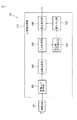
図2は、本発明を適用した画像処理システム101の一実施の形態を示す図である。画像処理システム101は、撮像装置111および画像処理装置112を含むように構成される。
FIG. 2 is a diagram showing an embodiment of an
撮像装置111は、図3を参照して後述するように、対数変換型の撮像素子を用いて約170dBの非常に広いダイナミックレンジで被写体を撮像し、撮像した被写体の画像の画像データを画像処理装置112に供給する。
As will be described later with reference to FIG. 3, the
画像処理装置112は、画像入力制御部121、画像記憶部122、差分処理部123、差分値分布検出部124、閾値決定部125、および、動き検出部126を含むように構成される。
The
画像入力制御部121は、撮像装置111から入力される画像データを画像記憶部122に記憶させる。
The image
画像記憶部122は、RAM(Random Access Memory)などの揮発性のメモリ、または、EEPROM(Electrically Erasable and Programmable Read Only Memory)などの不揮発性のメモリにより構成され、画像入力制御部121を介して、撮像装置111から入力される画像データを記憶する。
The
差分処理部123は、画像記憶部122から2枚のフレームの画像データを読み出す。差分処理部123は、2枚のフレーム間の画像データの同じ位置にある画素間の画素値の差分をとることにより差分データを生成する。差分処理部123は、生成した差分データを、差分値分布検出部124、および、動き検出部126に供給する。なお、以下、差分データの各画素の画素値を、差分値とも称する。
The
差分値分布検出部124は、図5を参照して後述するように、差分データの差分値の分布を検出する。差分値分布検出部124は、差分データの差分値の分布を示すデータを閾値決定部125に供給する。
The difference value
閾値決定部125は、図5を参照して後述するように、差分データの差分値の分布に基づいて、動いている被写体の画像の画素の差分値と、それ以外の動いていない被写体の画像の画素の差分値とを区分する閾値(以下、変動閾値と称する)を決定する。換言すれば、変動閾値は、被写体の動きにより画素値が変動した画素とそれ以外の画素とを区分する閾値である。閾値決定部125は、変動閾値示すデータを動き検出部126に供給する。
As will be described later with reference to FIG. 5, the threshold
動き検出部126は、図5を参照して後述するように、フレーム間の被写体の動きを検出し、検出した被写体の動きの方向および大きさを示すデータ(以下、動きデータと称する)を外部に出力する。
As will be described later with reference to FIG. 5, the
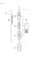
図3は、図2の撮像装置111の一実施の形態を示すブロック図である。撮像装置111は、レンズ131、および対数変換型撮像素子132を含むように構成される。対数変換型撮像素子132は、例えば、HDRC(High Dynamic Range CMOS(Complementary Metal Oxide Semiconductor))などの対数変換型の撮像素子とされ、光検出部141、対数変換部142、A/D変換部143、および撮像タイミング制御部144を含むように構成される。
FIG. 3 is a block diagram illustrating an embodiment of the
撮像装置111により撮像される被写体から発せられた光(あるいは、被写体により反射された光)は、レンズ131に入射し、対数変換型撮像素子132の光検出部141の図示せぬ光検出面に結像する。
The light emitted from the subject imaged by the imaging device 111 (or the light reflected by the subject) enters the
光検出部141は、例えば、複数のフォトダイオードからなる受光素子などにより構成される。光検出部141は、レンズ131により結像された被写体の光を、入射された光の明るさ(照度)に応じた電荷に変換し、変換した電荷を蓄積する。光検出部141は、撮像タイミング制御部144から供給される制御信号に同期して、蓄積した電荷を対数変換部142に供給する。
The
対数変換部142は、例えば、複数のMOSFET(Metal Oxide Semiconductor Field Effect Transistor)などにより構成される。対数変換部142は、MOSFETのサブスレッショルド特性を利用して、光検出部141から供給される電荷を、画素ごとに電荷の数(電流の強さ)の対数(被写体の光の光量の対数)にほぼ比例した電圧値に変換したアナログの電気信号を生成する。対数変換部142は、生成したアナログの電気信号をA/D変換部143に供給する。
The
A/D変換部143は、撮像タイミング制御部144から供給される制御信号に同期して、アナログの電気信号をデジタルの画像データにA/D変換する。例えば、14bitの符号なし2進数のデジタルの画像データに変換される場合、画像データの画素値は、最も暗い0から最も明るい214−1の範囲の値をとる。A/D変換部143は、変換したデジタルの画像データを画像処理装置112に供給する。なお、上述した画像データのビット数および画素値の範囲は、その一例であり、それぞれ14bitおよび0乃至214−1に限定されるものではない。
The A /
このように、撮像装置111は、光検出部141に入射した被写体の光の明るさ(入射光量)の対数に比例した画素値からなるデジタルの画像データを出力する。なお、対数変換型の撮像素子については、例えば、特表平7−506932公報などにその詳細が開示されている。
As described above, the
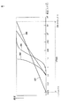
図4は、対数変換型撮像素子132、CCD撮像素子、銀塩フィルム、および、人の目の感度特性を示すグラフである。図4の横軸は、入射光の照度(単位は、ルクス(lux))の対数値を示し、縦軸は入射光の照度に対する感度を示している。線201は対数変換型撮像素子132の感度特性を示し、線202はCCD撮像素子の感度特性を示し、線203は銀塩フィルムの感度特性を示し、線204は人の目の感度特性を示している。なお、CCD撮像素子の感度特性を示す線202は図1の線1に対応し、人の目の感度特性を示す線204は図1の線2に対応する。
FIG. 4 is a graph showing sensitivity characteristics of the logarithmic conversion
対数変換型撮像素子132は、上述したように、入射光量の対数にほぼ比例した画素値からなる画像データを出力することにより、対数変換型撮像素子132を構成するフォトダイオードやMOSFETなどの容量を飽和させずに、CCD撮像素子、銀塩フィルム、および、人の目より広い、約1ミリルクスから太陽光の輝度より高い約500キロルクスまでの約170dBのダイナミックレンジで被写体を撮像することができる。
As described above, the logarithmic conversion
従って、対数変換型撮像素子132を用いた撮像装置111は、人が視認できる輝度範囲において、輝度クリッピングが発生しないため、絞りやシャッタースピードなどを調整して入射光量を調整する必要がない。すなわち、撮像装置111は、入射光量を調整しなくても、被写体の詳細な輝度分布を忠実に撮像することができる。
Accordingly, the
例えば、昼間に車内から車の前方を撮像する場合、画角内に太陽が入っていても、撮像装置111により撮像された画像は、入射光量を調整しなくても、太陽と前方の道路の輝度の分布を忠実に再現した画像となる。また、夜間に車内から車の前方を撮像する場合、対向車のヘッドライトが前方から照らされていても、撮像装置111により撮像された画像は、入射光量を調整しなくても、対向車のヘッドライトの光から自車のヘッドライトに照らされていない領域までの輝度の分布を忠実に再現した画像となる。
For example, when imaging the front of a vehicle from inside the vehicle during the daytime, the image captured by the
また、CCD撮像素子および銀塩フィルムでは、線202および線203に示されるように、ガンマ特性などの要因により感度特性が入射光の照度の対数に比例しないのに比べて、対数変換型撮像素子132では、感度特性が入射光の照度の対数にほぼ比例する。
Further, in the CCD image pickup device and the silver salt film, as shown by the
このように、対数変換型撮像素子132を用いた撮像装置111は、輝度クリッピングの発生、入射光量の調整、ガンマ特性の影響を受けないため、撮像装置111により撮像された画像データの画素値は、被写体の輝度の変動および被写体の動きをほぼ忠実に反映するように変動する。すなわち、フレーム間の画像データの差分をとった差分データの各画素の差分値は、被写体の輝度の変動および被写体の動きがほぼ忠実に反映された値となる。
As described above, the
また、撮像装置111から出力される画像データの画素値は、入射光量の対数にほぼ比例した値となるので、被写体に照射される光の明るさ(照度)に関わらず、その被写体を撮像した画像データにおける画素値の分布は、その被写体の反射率の分布がほぼ同様に反映されたものとなる。例えば、反射率の最大値と最小値の比率が10:1である被写体を、1回目と2回目とで約100倍の照度差がある光を照射して撮像した場合、1回目の画像データと2回目の画像データとの画素値の分布を示すヒストグラムの幅はほぼ同じ値(1=log1010)となる。一方、画像データの画素値が入射光量に比例する場合、1回目の画像データと2回目の画像データの画素値の分布を示すヒストグラムの幅の差は約100倍となる。
Further, since the pixel value of the image data output from the
また、被写体の輝度(反射率)の分布に関わらず、被写体の輝度がほぼ同じ比率で変動した場合、その被写体を撮像した画像データの画素値の変動値は、ほぼ同様になる。例えば、被写体内に輝度の比が100:1となる2つの領域がある場合、被写体に照射される光の照度がほぼ一様に変化し、被写体の輝度がほぼ同じ比率の+5%変動したとき、2つの領域に対応する画素値の変動値はほぼ同じ値(log101.05)となる。一方、画像データの画素値が入射光量に比例する場合、上述した2つの領域に対応する画素値の変動値の差は、約100倍となる。 Further, regardless of the distribution of the luminance (reflectance) of the subject, when the luminance of the subject fluctuates at substantially the same ratio, the variation values of the pixel values of the image data obtained by imaging the subject are substantially the same. For example, if there are two areas in the subject where the luminance ratio is 100: 1, the illuminance of the light radiated to the subject changes almost uniformly, and the subject's luminance changes by + 5%, which is almost the same ratio The variation values of the pixel values corresponding to the two areas are almost the same value (log 10 1.05). On the other hand, when the pixel value of the image data is proportional to the amount of incident light, the difference between the fluctuation values of the pixel values corresponding to the two regions described above is about 100 times.
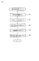
次に、図5のフローチャートを参照して、監視システム101により実行される動き検出処理を説明する。なお、この処理は、例えば、ユーザにより動き検出処理の開始の指令が、画像処理装置112に入力されたとき開始される。
Next, the motion detection process executed by the
ステップS1において、撮像装置111は被写体を撮像する。具体的には、撮像装置111は被写体を撮像し、撮像した画像データを画像入力制御部121に出力する。画像入力制御部121は、取得した画像データを画像記憶部122に記憶させる。
In step S1, the
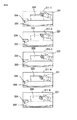
なお、以下、適宜、図6に示されるフレーム211−1乃至211−5が撮像装置111により撮像され、フレーム211−1とフレーム211−2の間における被写体の動き、および、フレーム211−3とフレーム211−4の間における被写体の動きを検出する場合の例について説明する。
Hereinafter, as appropriate, the frames 211-1 to 211-5 shown in FIG. 6 are imaged by the
なお、図6に示される全てのフレームには、手221、机222、椅子223、および、棚224が写っている。そのうち、机222、椅子223、および、棚224の位置は、全てのフレームにおいて同じである。机222は、フレーム内のほぼ下半分を占める位置にある。椅子223は、机222の後方であって、フレームの中央やや左よりの位置にある。棚224は、机222の後方かつ左側であって、フレームの縦方向のほぼ中央かつ左端にある。手221は、手のひらをほぼ正面に向けた状態で、机222および椅子223の前方であって、フレームの右側の位置にある。手221は、フレーム211−1から211−5に進むにつれて、手のひらを広げたまま、フレーム内の下方向に移動している。
Note that the
また、フレーム211−1乃至211−3において、周囲の明るさはほぼ一定であり、フレーム211−3とフレーム211−4との間において、周囲の明るさが暗くなり、フレーム211−4および211−5において、周囲の明るさはほぼ一定であるものとする。従って、フレーム211−4および211−5内の被写体の輝度は、フレーム211−1乃至211−3内の被写体の輝度に比べて、全体的にほぼ一様に下がっている。 In the frames 211-1 to 211-3, the ambient brightness is substantially constant, and the ambient brightness becomes dark between the frames 211-3 and 211-4. In −5, it is assumed that the ambient brightness is substantially constant. Therefore, the luminance of the subjects in the frames 211-4 and 211-5 is substantially uniform as compared with the luminance of the subjects in the frames 211-1 to 211-3.
ステップS2において、差分処理部123は、差分データを生成する。具体的には、例えば、フレーム211−1とフレーム211−2との間の画像データの差分を取る場合、差分処理部123は、フレーム211−1および211−2の画像データを画像記憶部122から読み出す。差分処理部123は、読み出した画像データの同じ位置の画素間の画素値の差分をとることにより差分データを生成する。差分処理部123は、生成した差分データを差分値分布検出部124および動き検出部126に供給する。
In step S2, the
図7の差分画像231は、フレーム211−1と211−2との間の差分をとった差分データに基づく画像を模式的に示しており、差分画像232は、フレーム211−3と211−4との間の差分をとった差分データに基づく画像を模式的に示している。
A
上述したように、撮像装置111から出力される画像データの画素値は、被写体の輝度の変動および被写体の動きをほぼ忠実に反映するよう変動する。従って、差分画像231において、フレーム間で動いている被写体に対応する(被写体の動きがあった)領域(フレーム211−1または211−2において手221が写っている領域)は、差分値の絶対値は大きくなり、明るくなる。また、フレーム211−1とフレーム211−2間で、周囲の明るさがほぼ同じで、被写体の輝度がほとんど変動しないため、差分画像231において、フレーム間で動いていない被写体に対応する(被写体の動きがなかった)領域(フレーム211−1および211−2において手221が写っていない領域)は、差分値の絶対値が0かまたはそれに近い値となり、非常に暗くなる。従って、差分画像231において、フレーム間で動いている被写体に対応する領域が明確に現れる。
As described above, the pixel value of the image data output from the
また、動いている被写体の移動方向の輪郭付近の領域(フレーム211−1で手221が写っていなくて、フレーム211−2で手221が写っている領域)は、特に画素値の変動が大きく、差分画像231において、顕著に明るくなる。従って、差分画像231において、動いている被写体(手221)の移動方向の輪郭が明確に現れる。
In addition, in the region near the contour of the moving subject in the moving direction (the region where the
また、フレーム211−3とフレーム211−4の間で、周囲の明るさが変化し、被写体の輝度が全体的にほぼ一様に変動することにより、差分画像232において、フレーム間で動いていない被写体に対応する領域(フレーム211−3および211−4において手221が写っていない領域)は、差分画像231におけるフレーム間で動いていない被写体に対応する領域に比べて、ほとんどの画素の差分値の絶対値が大きくなり、全体的に明るくなる。しかし、通常のフレーム速度(例えば、30fps(Frame per second))において、フレーム間の周囲の明るさの変動は小さいため、差分画像232においても、フレーム間で動いている被写体に対応する領域(フレーム211−3または211−4において手221が写っている領域)が明確に現れる。
Further, the brightness of the surroundings changes between the frames 211-3 and 211-4, and the luminance of the subject fluctuates almost uniformly, so that the
また、動いている被写体の移動方向の輪郭付近の領域(フレーム211−3で手221が写っていなくて、フレーム211−4で手221が写っている領域)は、特に画素値の変動が大きく、差分画像232において、顕著に明るくなる。従って、差分画像232において、動いている被写体(手221)の移動方向の輪郭が明確に現れる。
In addition, in the region near the contour of the moving subject in the moving direction (the region in which the
ステップS3において、差分値分布検出部124は、差分データの差分値の分布を検出する。具体的には、差分値分布検出部124は、差分値の絶対値の範囲を所定の数(例えば、100)の階級に区分して、差分データ内の各画素の差分値の絶対値がどの階級に属するかを検出する。そして、各階級に属する画素の数(度数)を集計することにより、差分データの差分値の分布を検出する。すなわち、差分値の絶対値の度数分布を検出する。なお、例えば、階級の数が100の場合、各階級には、含まれる差分値の絶対値が小さい階級から順に0から99までの値(以下、階級識別値と称する)が割り当てられる。
In step S3, the difference value
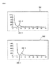
図8のグラフ241は、差分画像231の差分データの差分値の分布を示し、グラフ242は、差分画像232の差分データの差分値の分布を示している。グラフ241および242において、横軸は階級識別値を示し、縦軸は各階級に属する画素の数を示している。また、グラフ241および242において、縦軸方向の画素数が1000を超える領域の表示を省略している。
The
グラフ241において、階級識別値が0または0に近い階級に属する画素数、すなわち、差分値の絶対値が0または0に近い値の画素数が突出している。この画素数の突出したピークは、差分画像231において、フレーム間で被写体の動いていない領域の画素数が反映されたものである。
In the
そして、グラフ241を原点から階級識別値(差分値の絶対値)が大きくなる方向(右方向)に見た場合、画素数は急激に減少し、極小点241−1において極小となる。なお、フレーム211−1とフレーム211−2との間で周囲の明るさがほとんど変化せず、被写体が動いていない領域の画素値はほとんど変動しないため、極小点241−1は原点に近い位置となる。その後、画素数は増加に転じ、極大点241−2において極大となり、再び減少傾向となり、階級識別値(差分値の絶対値)が大きくなるに従い、0に近づいていく。図7の差分画像231を見て明らかなように、この極小点241−1より右側の画素数の変化は、差分値の絶対値が大きい被写体(手221)が動いている領域内の画素数が反映されたものである。
Then, when the
差分画像232の差分データでは、フレーム211−3とフレーム211−4との間で周囲の明るさが変化したため、全体的に差分値の絶対値が大きくなる傾向となる。また、上述したように、撮像装置111から出力される画像データの画素値の分布は、被写体に照射される光の照度に関わらず、被写体の反射率の分布がほぼ同様に反映される。従って、グラフ242の波形は、グラフ241の波形を右方向(差分値の絶対値が大きくなる方向)に平行移動させたものに近い波形となる。それに合わせて、極小点242−1および極大点242−2は、極大点241−1および極小点241−2と比べて、右方向に移動する。
In the difference data of the
差分値分布検出部124は、差分データの差分値の分布を示すデータを閾値決定部125に供給する。
The difference value
なお、差分データの差分値の分布を、差分値の絶対値の範囲を階級に区分せずに、差分値ごとに検出するようにしてもよい。 In addition, you may make it detect the distribution of the difference value of difference data for every difference value, without dividing the range of the absolute value of a difference value into a class.
ステップS4において、閾値決定部125は、変動閾値を決定する。具体的には、閾値決定部125は、差分データの差分値の分布において、画素数が極小となる階級のうち、階級識別値が最小値となる階級(以下、閾値階級と称する)を求める。例えば、差分画像231の差分データにおいて、グラフ241の極小点241−1に対応する階級が閾値階級となり、差分画像232の差分データにおいて、グラフ242の極小点242−1に対応する階級が閾値階級となる。閾値決定部125は、例えば、閾値階級の範囲内の差分値の絶対値の最大値、最小値、または、中間値を変動閾値とする。
In step S4, the threshold
このように、差分データの差分値の分布において、周囲の明るさの変化に関わらず、動いている被写体の画像の画素の差分値と、動いていない被写体の画像の画素の差分値との差が明確に現れるため、変動閾値を簡単かつ確実に決定することができる。 Thus, in the difference value distribution of the difference data, the difference between the pixel difference value of the moving subject image and the pixel difference value of the non-moving subject image regardless of the change in ambient brightness. Clearly appears, the variation threshold can be determined easily and reliably.
なお、差分データの差分値の分布を、差分値の絶対値の範囲を所定の範囲の階級に区分せずに検出した場合、変動閾値は、差分値の分布において、差分値の絶対値が同じ画素の数が極小となる差分値の絶対値のうち最小の値に決定される。 In addition, when the distribution of the difference value of the difference data is detected without dividing the absolute value range of the difference value into a class of a predetermined range, the variation threshold is the same as the absolute value of the difference value in the difference value distribution. The absolute value of the difference value that minimizes the number of pixels is determined to be the smallest value.
また、差分値の分布の画素数の細かな変動(振動)による変動閾値の誤検出を防止するために、差分値の絶対値の範囲を階級に区分した場合、画素数が所定の閾値以下となる階級のみを閾値階級の対象とするようにし、差分値の絶対値の範囲を階級に区分しない場合、画素数が所定の閾値以下となる画素値の絶対値のみを変動閾値とするようにしてもよい。 In addition, when the range of absolute value of the difference value is divided into classes in order to prevent erroneous detection of the fluctuation threshold due to fine fluctuation (vibration) of the number of pixels of the difference value distribution, the number of pixels is less than a predetermined threshold value. If the absolute value range of the difference value is not divided into classes, only the absolute value of the pixel value whose number of pixels is equal to or less than the predetermined threshold value is set as the variation threshold value. Also good.
閾値決定部125は、変動閾値を示すデータを動き検出部126に供給する。
The threshold
ステップS5において、動き検出部126は、被写体の動きを検出し、動き検出処理は終了する。具体的には、まず、動き検出部126は、差分データから、動いている被写体に対応する領域を抽出する。例えば、動き検出部126は、差分データにおいて、差分値の絶対値が変動閾値未満の画素の値(差分値)を0にする。これにより、差分データから、差分値の絶対値が変動閾値以上の画素の領域、すなわち、動いている被写体に対応する領域(以下、抽出領域と称する)が抽出される。
In step S5, the
次に、動き検出部126は、抽出領域内の画像の輪郭を抽出する。差分画像231および232に示されるように、差分画像において、動いている被写体の移動方向の輪郭が明確に現れるため、輪郭抽出の手法によらず、動いている被写体の移動方向の輪郭を、ほぼ正確に抽出することができる。また、抽出領域以外の領域については、輪郭の抽出処理を行う必要がないため、輪郭抽出に要する計算量を削減することができる。
Next, the
そして、動き検出部126は、動いている被写体の移動方向の輪郭に基づいて、被写体の動きベクトルを検出する。例えば、動き検出部126は、動いている被写体の移動方向の輪郭の幅に基づいて、被写体の動きベクトルの大きさを求め、差分データにおける差分値の位置分布に基づいて、被写体の動きベクトルの方向を求める。動き検出部126は、被写体の動きベクトルを示す動きデータを外部に出力する。
Then, the
以上のようにして、被写体の動きを簡単かつ確実に検出することができる。これにより、動き検出を行う画像処理装置や半導体チップなどを小型化、低消費電力化、および、低価格化することができる。また、周囲の明るさが大きく変動する環境下においても、被写体の動きを確実に検出することができる。さらに、被写体の輝度などに応じて、入射光量を調整する必要がないため、動き検出処理に要する時間を短縮することができる。 As described above, the movement of the subject can be detected easily and reliably. As a result, it is possible to reduce the size, the power consumption, and the price of an image processing device or a semiconductor chip that performs motion detection. In addition, it is possible to reliably detect the movement of the subject even in an environment where the brightness of the surroundings varies greatly. Furthermore, since it is not necessary to adjust the amount of incident light according to the luminance of the subject, the time required for the motion detection process can be shortened.
なお、撮像装置111のフレーム間隔は、動きを検出する対象となる被写体の動きの早さに応じて設定することが望ましい。例えば、被写体のフレーム間における移動距離が、検出したい移動距離の最小値となるようにフレーム間隔を設定することが望ましい。例えば、手のひらの動きを検出する場合、フレーム間の手の移動距離が指の幅程度となるフレーム間隔(例えば、30fps(Frame per second))に設定する。これにより、フレーム間の周囲の明るさの変動による画素値の変動を抑えることができ、被写体の動きによる画素値の変動値と、他の要因による画素値の変動値との差をより大きくすることができるため、被写体の動きの検出精度が向上する。
Note that the frame interval of the
また、以上では、図8の極小点241−1および242−1を、グラフ241および242を原点から階級識別値(差分値の絶対値)が大きくなる方向(右方向)に見て検索する例を説明したが、グラフ241および242を階級識別値の最大値から階級識別値(差分値の絶対値)が小さくなる方向(左方向)に見て、まず、顕著な極大点241−2および242−2を検索して、その次に画素数が極小となる点を検索することにより、極小点241−1および242−1を検索するようにしてもよい。
In the above example, the local minimum points 241-1 and 242-1 in FIG. 8 are searched by looking at the
なお、本発明は、ジェスチャインタフェースを用いた機器に適用することができる。例えば、本発明を車載用のナビゲーションシステムに適用することにより、周囲の明るさが大きく変動する走行中においても、誤動作のないジェスチャインタフェースを実現することができる。また、例えば、本発明を携帯電話機やデジタルカメラに適用することにより、使用する環境によって周囲の明るさが大きく変動しても、ユーザのジェスチャにより携帯電話機やデジタルカメラの操作が行えるようになる。 The present invention can be applied to a device using a gesture interface. For example, by applying the present invention to an in-vehicle navigation system, it is possible to realize a gesture interface that does not malfunction even during traveling in which ambient brightness varies greatly. Further, for example, by applying the present invention to a mobile phone or a digital camera, the mobile phone or the digital camera can be operated by a user's gesture even if the ambient brightness varies greatly depending on the environment in which it is used.
上述した一連の処理は、ハードウェアにより実行させることもできるし、ソフトウェアにより実行させることもできる。一連の処理をソフトウェアにより実行させる場合には、そのソフトウェアを構成するプログラムが、専用のハードウェアに組み込まれているコンピュータ、または、各種のプログラムをインストールすることで、各種の機能を実行することが可能な、例えば汎用のパーソナルコンピュータなどに、ネットワークや記録媒体からインストールされる。 The series of processes described above can be executed by hardware or can be executed by software. When a series of processing is executed by software, a program constituting the software may execute various functions by installing a computer incorporated in dedicated hardware or various programs. For example, it is installed from a network or a recording medium into a general-purpose personal computer or the like.
図9は、汎用のパーソナルコンピュータ900の内部の構成例を示す図である。CPU(Central Processing Unit)901は、ROM(Read Only Memory)902に記憶されているプログラム、または記録部908からRAM(Random Access Memory)903にロードされたプログラムに従って各種の処理を実行する。RAM903にはまた、CPU901が各種の処理を実行する上において必要なデータなども適宜記憶される。
FIG. 9 is a diagram illustrating an internal configuration example of a general-purpose
CPU901、ROM902、およびRAM903は、バス904を介して相互に接続されている。このバス904にはまた、入出力インタフェース905も接続されている。
The
入出力インタフェース905には、ボタン、スイッチ、キーボードあるいはマウスなどで構成される入力部906、CRT(Cathode Ray Tube)やLCD(Liquid Crystal Display)などのディスプレイ、並びにスピーカなどで構成される出力部907、ハードディスクなどで構成される記録部908、およびモデムやターミナルアダプタなどで構成される通信部909が接続されている。通信部909は、インターネットを含むネットワークを介して通信処理を行う。
The input /
入出力インタフェース905にはまた、必要に応じてドライブ910が接続され、磁気ディスク、光ディスク、光磁気ディスク、あるいは半導体メモリなどよりなるリムーバブルメディア911が適宜装着され、そこから読み出されたコンピュータプログラムが、記録部908にインストールされる。
A
コンピュータにインストールされ、コンピュータによって実行可能な状態とされるプログラムを記録する記録媒体は、図9に示されるように、装置本体とは別に、ユーザにプログラムを提供するために配布される、プログラムが記録されている磁気ディスク(フレキシブルディスクを含む)、光ディスク(CD-ROM(Compact Disc-Read Only Memory)、DVD(Digital Versatile Disc)を含む)、光磁気ディスク(MD(Mini-Disc)(登録商標)を含む)、もしくは半導体メモリなどよりなるリムーバブルメディア911により構成されるだけでなく、装置本体にあらかじめ組み込まれた状態でユーザに提供される、プログラムが記録されているROM902または記録部908に含まれるハードディスクなどで構成される。
As shown in FIG. 9, a recording medium that records a program that is installed in a computer and can be executed by the computer is distributed to provide a program to a user separately from the apparatus main body. Recording magnetic disk (including flexible disk), optical disk (including CD-ROM (Compact Disc-Read Only Memory), DVD (Digital Versatile Disc)), magneto-optical disk (MD (Mini-Disc) (registered trademark) )), Or a
なお、本明細書において、プログラム格納媒体に格納されるプログラムを記述するステップは、記載された順序に沿って時系列的に行われる処理はもちろん、必ずしも時系列的に処理されなくとも、並列的あるいは個別に実行される処理をも含むものである。 In the present specification, the step of describing the program stored in the program storage medium is not limited to the processing performed in chronological order according to the described order, but is not necessarily performed in chronological order. Or the process performed separately is also included.
また、本明細書において、システムの用語は、複数の装置、手段などにより構成される全体的な装置を意味するものである。 Further, in the present specification, the term “system” means an overall apparatus constituted by a plurality of apparatuses and means.
101 画像処理システム
111 撮像装置
112 画像処理装置
121 画像入力制御部
122 画像記憶部
123 差分処理部
124 差分値分布検出部
125 閾値決定部
126 動き検出部
132 対数変換型撮像素子
141 光検出部
142 対数変換部
901 CPU
902 ROM
903 RAM
908 記録部
910 ドライブ
921 リムーバブルメディア
DESCRIPTION OF
902 ROM
903 RAM
908
Claims (8)
前記撮像装置から出力された前記画像データの第1のフレームの各画素値と第2のフレームの各画素値との差分である差分値からなる差分データを生成する差分データ生成手段と、
前記差分データにおける前記差分値の絶対値の度数分布において、画素数が極小となる階級のうち前記差分値の絶対値の範囲が最小の階級の範囲内の前記差分値の絶対値を変動閾値に設定する閾値設定手段と、
前記差分データにおいて前記差分値の絶対値が前記変動閾値以上の画素からなる抽出領域内の前記被写体の輪郭に基づいて、前記被写体の動きを検出する動き検出手段と
を含むことを特徴とする画像処理システム。 An imaging device that captures an image of a subject and outputs image data composed of pixel values substantially proportional to the logarithm of the incident light amount;
Difference data generating means for generating difference data comprising difference values that are differences between the pixel values of the first frame and the pixel values of the second frame of the image data output from the imaging device;
Varying the absolute value of the difference value in the range of Oite the frequency distribution of the absolute value, the class range minimum of the absolute value of the difference value among the classes in which the number of pixels becomes minimum the difference value in the difference data Threshold setting means for setting the threshold;
A motion detection unit that detects a motion of the subject based on an outline of the subject in an extraction region composed of pixels in which the absolute value of the difference value is greater than or equal to the variation threshold in the difference data . Processing system.
前記差分データにおける前記差分値の絶対値の度数分布において、画素数が極小となる階級のうち前記差分値の絶対値が最小の階級の範囲内の前記差分値の絶対値を変動閾値に設定する閾値設定手段と、
前記差分データにおいて前記差分値の絶対値が前記変動閾値以上の画素からなる抽出領域内の前記被写体の輪郭に基づいて、前記被写体の動きを検出する動き検出手段と
を含むことを特徴とする画像処理装置。 Image data of an image obtained by capturing an image of a subject, and a difference that is a difference between each pixel value of the first frame and each pixel value of the second frame of image data composed of pixel values substantially proportional to the logarithm of the incident light quantity Difference data generation means for generating difference data consisting of values;
Oite the frequency distribution of the absolute value of the difference value in the difference data, the variation threshold absolute value of the difference value in the range absolute value of the minimum of the rank of the difference value among the classes in which the number of pixels is minimum and a threshold value setting means for setting,
A motion detection unit that detects a motion of the subject based on an outline of the subject in an extraction region composed of pixels in which the absolute value of the difference value is greater than or equal to the variation threshold in the difference data . Processing equipment.
ことを特徴とする請求項2に記載の画像処理装置。The image processing apparatus according to claim 2.
ことを特徴とする請求項2に記載の画像処理装置。 The image data, by using a subthreshold characteristic of a semiconductor, according to claim 2, characterized in that output by approximately proportional to the logarithm conversion type image pickup apparatus having an image pickup device that outputs a pixel value to the logarithm of incident light quantity An image processing apparatus according to 1.
ことを特徴とする請求項4に記載の画像処理装置。 The image processing apparatus according to claim 4, wherein the imaging element is HDRC (High Dynamic Range CMOS (Complementary Metal Oxide Semiconductor)).
前記差分データにおける前記差分値の絶対値の度数分布において、画素数が極小となる階級のうち前記差分値の絶対値が最小の階級の範囲内の前記差分値の絶対値を変動閾値に設定する閾値設定ステップと、
前記差分データにおいて前記差分値の絶対値が前記変動閾値以上の画素からなる抽出領域内の前記被写体の輪郭に基づいて、前記被写体の動きを検出する動き検出ステップと
を含むことを特徴とする画像処理方法。 Image data of an image obtained by capturing an image of a subject, and a difference that is a difference between each pixel value of the first frame and each pixel value of the second frame of image data composed of pixel values substantially proportional to the logarithm of the incident light quantity A difference data generation step for generating difference data consisting of values;
Oite the frequency distribution of the absolute value of the difference value in the difference data, the variation threshold absolute value of the difference value in the range absolute value of the minimum of the rank of the difference value among the classes in which the number of pixels is minimum A threshold setting step to be set ;
A motion detection step of detecting a motion of the subject based on an outline of the subject in an extraction area composed of pixels in which the absolute value of the difference value is greater than or equal to the variation threshold in the difference data . Processing method.
前記差分データにおける前記差分値の絶対値の度数分布において、画素数が極小となる階級のうち前記差分値の絶対値が最小の階級の範囲内の前記差分値の絶対値を変動閾値に設定する閾値設定ステップと、
前記差分データにおいて前記差分値の絶対値が前記変動閾値以上の画素からなる抽出領域内の前記被写体の輪郭に基づいて、前記被写体の動きを検出する動き検出ステップと
を含むことを特徴とするプログラム。 Image data of an image obtained by capturing an image of a subject, and a difference that is a difference between each pixel value of the first frame and each pixel value of the second frame of image data composed of pixel values substantially proportional to the logarithm of the incident light quantity A difference data generation step for generating difference data consisting of values;
Oite the frequency distribution of the absolute value of the difference value in the difference data, the variation threshold absolute value of the difference value in the range absolute value of the minimum of the rank of the difference value among the classes in which the number of pixels is minimum A threshold setting step to be set ;
A motion detection step of detecting a motion of the subject based on an outline of the subject in an extraction region composed of pixels in which the absolute value of the difference value is greater than or equal to the variation threshold in the difference data . .
Priority Applications (1)
| Application Number | Priority Date | Filing Date | Title |
|---|---|---|---|
| JP2005073752A JP4635663B2 (en) | 2005-03-15 | 2005-03-15 | Image processing system, image processing apparatus and method, recording medium, and program |
Applications Claiming Priority (1)
| Application Number | Priority Date | Filing Date | Title |
|---|---|---|---|
| JP2005073752A JP4635663B2 (en) | 2005-03-15 | 2005-03-15 | Image processing system, image processing apparatus and method, recording medium, and program |
Publications (2)
| Publication Number | Publication Date |
|---|---|
| JP2006259899A JP2006259899A (en) | 2006-09-28 |
| JP4635663B2 true JP4635663B2 (en) | 2011-02-23 |
Family
ID=37099121
Family Applications (1)
| Application Number | Title | Priority Date | Filing Date |
|---|---|---|---|
| JP2005073752A Expired - Fee Related JP4635663B2 (en) | 2005-03-15 | 2005-03-15 | Image processing system, image processing apparatus and method, recording medium, and program |
Country Status (1)
| Country | Link |
|---|---|
| JP (1) | JP4635663B2 (en) |
Families Citing this family (6)
| Publication number | Priority date | Publication date | Assignee | Title |
|---|---|---|---|---|
| US8525888B2 (en) | 2008-01-17 | 2013-09-03 | Nikon Corporation | Electronic camera with image sensor and rangefinding unit |
| US8687918B2 (en) | 2008-03-05 | 2014-04-01 | Semiconductor Energy Laboratory Co., Ltd. | Image processing method, image processing system, and computer program |
| FR2967804B1 (en) * | 2010-11-19 | 2013-01-04 | Total Immersion | METHOD AND DEVICE FOR DETECTING AND TRACKING REAL-TIME MOVING NON-RIGID OBJECTS IN A VIDEO STREAM ENABLING A USER TO INTERACT WITH A COMPUTER SYSTEM |
| JP5994425B2 (en) * | 2012-06-25 | 2016-09-21 | オムロン株式会社 | Game machine |
| JP5949207B2 (en) * | 2012-06-25 | 2016-07-06 | オムロン株式会社 | Motion sensor and object motion detection method |
| WO2014002803A1 (en) * | 2012-06-25 | 2014-01-03 | オムロン株式会社 | Motion sensor, method for detecting object action, and game device |
Family Cites Families (5)
| Publication number | Priority date | Publication date | Assignee | Title |
|---|---|---|---|---|
| JPH08106534A (en) * | 1994-10-06 | 1996-04-23 | Hitachi Ltd | Moving object detection device |
| JP4020982B2 (en) * | 1995-03-10 | 2007-12-12 | 松下電器産業株式会社 | Moving image processing device |
| JPH09293141A (en) * | 1996-04-24 | 1997-11-11 | Hitachi Ltd | Moving object detection device |
| JP4300654B2 (en) * | 1999-07-22 | 2009-07-22 | コニカミノルタホールディングス株式会社 | Solid-state imaging device |
| JP2004304378A (en) * | 2003-03-31 | 2004-10-28 | Minolta Co Ltd | Photographing apparatus |
-
2005
- 2005-03-15 JP JP2005073752A patent/JP4635663B2/en not_active Expired - Fee Related
Also Published As
| Publication number | Publication date |
|---|---|
| JP2006259899A (en) | 2006-09-28 |
Similar Documents
| Publication | Publication Date | Title |
|---|---|---|
| JP4678487B2 (en) | Image processing system, image processing apparatus and method, recording medium, and program | |
| KR102523510B1 (en) | Generation of static images using event cameras | |
| US7936336B2 (en) | Optical mouse and image capture chip thereof | |
| KR101468351B1 (en) | Object tracking device, object tracking method, and control program | |
| KR101661215B1 (en) | Image processing method and image processing apparatus | |
| JP4835593B2 (en) | Image processing apparatus, image processing method, program, and recording medium | |
| CN109903324B (en) | Depth image acquisition method and device | |
| US9674441B2 (en) | Image processing apparatus, image processing method, and storage medium | |
| JP4985394B2 (en) | Image processing apparatus and method, program, and recording medium | |
| EP1871093A1 (en) | Image processor, image processing method, image processing system, program and recording medium | |
| CN111246092B (en) | Image processing method, device, storage medium and electronic device | |
| US20150093032A1 (en) | Image processing apparatus and method, and program | |
| CN110519485A (en) | Image processing method, image processing device, storage medium and electronic equipment | |
| US10311327B2 (en) | Image processing apparatus, method of controlling the same, and storage medium | |
| WO2021043061A1 (en) | Image processing method and apparatus, and storage medium and electronic device | |
| CN104902182A (en) | Method and device for realizing continuous auto-focus | |
| WO2007074659A1 (en) | Video signal processing method and video signal processing device | |
| US8717491B2 (en) | Auto focusing method, recording medium for recording the method, and auto focusing apparatus | |
| JP4635663B2 (en) | Image processing system, image processing apparatus and method, recording medium, and program | |
| KR102861769B1 (en) | Image processing method and appratus | |
| KR102809465B1 (en) | Delay equalization in event-based vision sensors | |
| KR20080032746A (en) | Motion recognition method and device | |
| US20220408008A1 (en) | High-dynamic-range detecting system | |
| US12088925B1 (en) | Flicker detection using event-based readout circuits | |
| CN101142811A (en) | Image processing apparatus, image processing method, program, and recording medium |
Legal Events
| Date | Code | Title | Description |
|---|---|---|---|
| A621 | Written request for application examination |
Free format text: JAPANESE INTERMEDIATE CODE: A621 Effective date: 20080117 |
|
| A977 | Report on retrieval |
Free format text: JAPANESE INTERMEDIATE CODE: A971007 Effective date: 20100813 |
|
| A131 | Notification of reasons for refusal |
Free format text: JAPANESE INTERMEDIATE CODE: A131 Effective date: 20100824 |
|
| A521 | Request for written amendment filed |
Free format text: JAPANESE INTERMEDIATE CODE: A523 Effective date: 20101008 |
|
| TRDD | Decision of grant or rejection written | ||
| A01 | Written decision to grant a patent or to grant a registration (utility model) |
Free format text: JAPANESE INTERMEDIATE CODE: A01 Effective date: 20101026 |
|
| A01 | Written decision to grant a patent or to grant a registration (utility model) |
Free format text: JAPANESE INTERMEDIATE CODE: A01 |
|
| A61 | First payment of annual fees (during grant procedure) |
Free format text: JAPANESE INTERMEDIATE CODE: A61 Effective date: 20101108 |
|
| FPAY | Renewal fee payment (event date is renewal date of database) |
Free format text: PAYMENT UNTIL: 20131203 Year of fee payment: 3 |
|
| R150 | Certificate of patent or registration of utility model |
Ref document number: 4635663 Country of ref document: JP Free format text: JAPANESE INTERMEDIATE CODE: R150 Free format text: JAPANESE INTERMEDIATE CODE: R150 |
|
| R250 | Receipt of annual fees |
Free format text: JAPANESE INTERMEDIATE CODE: R250 |
|
| LAPS | Cancellation because of no payment of annual fees |