JP4635648B2 - Vehicle steering system - Google Patents

Vehicle steering system Download PDF

Info

Publication number
JP4635648B2
JP4635648B2 JP2005057613A JP2005057613A JP4635648B2 JP 4635648 B2 JP4635648 B2 JP 4635648B2 JP 2005057613 A JP2005057613 A JP 2005057613A JP 2005057613 A JP2005057613 A JP 2005057613A JP 4635648 B2 JP4635648 B2 JP 4635648B2
Authority
JP
Japan
Prior art keywords
steering
reaction force
control
road surface
active
Prior art date
Legal status (The legal status is an assumption and is not a legal conclusion. Google has not performed a legal analysis and makes no representation as to the accuracy of the status listed.)
Expired - Fee Related
Application number
JP2005057613A
Other languages
Japanese (ja)
Other versions
JP2006240440A (en
Inventor
由之 柴田
富夫 永田
省二 小川
寿男 高野
Current Assignee (The listed assignees may be inaccurate. Google has not performed a legal analysis and makes no representation or warranty as to the accuracy of the list.)
JTEKT Corp
Original Assignee
JTEKT Corp
Priority date (The priority date is an assumption and is not a legal conclusion. Google has not performed a legal analysis and makes no representation as to the accuracy of the date listed.)
Filing date
Publication date
Application filed by JTEKT Corp filed Critical JTEKT Corp
Priority to JP2005057613A priority Critical patent/JP4635648B2/en
Publication of JP2006240440A publication Critical patent/JP2006240440A/en
Application granted granted Critical
Publication of JP4635648B2 publication Critical patent/JP4635648B2/en
Anticipated expiration legal-status Critical
Expired - Fee Related legal-status Critical Current

Links

Images

Landscapes

  • Steering Control In Accordance With Driving Conditions (AREA)
  • Power Steering Mechanism (AREA)

Description

本発明は、車両用操舵装置に関するものである。   The present invention relates to a vehicle steering apparatus.

近年、各種センサにより検出される車両状態量及び車両周囲の状況信号(車間距離や白線検知信号等)に基づいて、ステアリング操作によらず自動的に転舵輪の舵角(転舵角)を制御することにより、所謂レーンキープ等、車両の自動操縦を可能とする車両用操舵装置が提案されている。そして、こうした自動操舵機能を備えたものにおいては、その自動操縦自体の完成度はもとより、同制御の終了を速やかに運転者に知らしめることもまた重要な課題の一つとなっている。   In recent years, the steering angle (steering angle) of the steered wheels is automatically controlled regardless of the steering operation based on the vehicle state quantity detected by various sensors and the situation signals around the vehicle (distance between vehicles, white line detection signal, etc.) Thus, there has been proposed a vehicle steering apparatus that enables automatic steering of the vehicle, such as a so-called lane keep. For those equipped with such an automatic steering function, not only the completeness of the automatic steering itself but also promptly informing the driver of the end of the control is also an important issue.

例えば、上例のレーンキープでは、走行路の白線(マーキング)が途切れた場合等、明確なる状況信号の検知が不能となった場合に、その自動制御は終了する。従って、こうした場合、当然のことながら、その操縦(運転)は速やかに運転者に引き継がれなければならない。しかしながら、そもそも、こうした自動操縦機能は運転者の負担を軽減すべく導入されるものであり、自動操縦中の運転者に、自らが運転する時と同様の緊張感及び注意力は期待できない。このため、音響的又は視覚的な手法によりその終了を告知したとしても、聞き逃され、或いは見過ごされる可能性は否定できず、その対応の遅れによって車両が走行車線から逸脱してしまうおそれがある。そこで、従来、その自動操縦制御の終了時、ステアリングに振動等の触覚的信号を付与するものがある。そして、このような構成を採用することで、運転者に対しその自動制御の終了を速やかに知らしめることができるようになる(例えば、特許文献1参照)。   For example, in the lane keep in the above example, the automatic control ends when the clear status signal cannot be detected, such as when the white line (marking) of the travel path is interrupted. Therefore, in such a case, as a matter of course, the maneuvering (driving) must be immediately handed over to the driver. However, in the first place, such an autopilot function is introduced in order to reduce the burden on the driver, and a driver who is driving automatically cannot expect the same tension and attention as when driving himself. For this reason, even if the end is announced by an acoustic or visual method, the possibility of being overlooked or overlooked cannot be denied, and the vehicle may deviate from the driving lane due to a delay in the response. . Therefore, there is a conventional technique that gives a tactile signal such as vibration to the steering wheel at the end of the automatic steering control. And by employ | adopting such a structure, a driver | operator can be immediately notified about the completion | finish of the automatic control (for example, refer patent document 1) here.

ところで、自動操舵システムには、上記のような自動操縦機能以外にも、車両状態量と車両の運動状態との関係をモデル化した車両モデルに基づいて、車両のヨーモーメントを制御すべく自動的に転舵輪の舵角(転舵角)を変更するものがある(アクティブ転舵制御、例えば、特許文献2参照)。そして、このようなアクティブ転舵制御には、上記自動操縦制御時とは、全く逆の要因によって引き起こされる問題がある。   By the way, in addition to the automatic steering function as described above, the automatic steering system automatically controls the yaw moment of the vehicle based on the vehicle model that models the relationship between the vehicle state quantity and the vehicle motion state. There are some which change the steering angle (steering angle) of the steered wheels (active steering control, for example, see Patent Document 2). Such active steering control has a problem caused by factors that are completely opposite to those in the automatic steering control.

即ち、アクティブ転舵制御により与えられる転舵輪の舵角は、通常、ステアリングの舵角(操舵角)に応じたものとならない。そのため、転舵輪に作用する路面反力もまたその操舵角に応じたものとはならず、ステアリングに運転者の想定と反する操舵反力が作用することになる。そして、アクティブ転舵制御は、基本的に運転者自らの運転中において、必要に応じて速やかに実行されるものであり、このとき、運転者は緊張感及び注意力の何れもが高い状態にある。従って、運転者は、そのアクティブ転舵制御時の操舵反力の変化に対して敏感に反応しやすく、その変動を操舵フィーリングの悪化として捉えるおそれがある。   That is, the steering angle of the steered wheels given by the active steering control does not usually correspond to the steering angle (steering angle) of the steering. Therefore, the road surface reaction force acting on the steered wheels also does not correspond to the steering angle, and a steering reaction force contrary to the driver's assumption acts on the steering. The active steering control is basically executed promptly as needed during the driver's own driving. At this time, the driver is in a state where both the tension and the attention are high. is there. Therefore, the driver tends to react sensitively to the change in the steering reaction force during the active steering control, and there is a risk that the fluctuation is regarded as a deterioration in the steering feeling.

そこで、従来、こうした操舵反力の変動に伴う操舵フィーリングの悪化を抑制すべく、路面反力に応じた操舵反力をステアリングに付与すべく制御される反力アクチュエータを備えた所謂ステアバイワイヤ式の車両用操舵装置において、路面反力を操舵反力として反映させる路面反力反映モードと、路面反力を反映させない解除モードとを有し、その車両状態に応じて、これら2つのモードを切り替え可能としたものがある(例えば、特許文献3参照)。そして、このような構成をアクティブ転舵制御時に適用することにより、上記のごとく、運転者の想定に反する操舵反力を付与することによる操舵フィーリングの悪化を防止することができるようになる。
特開2004−210276号公報 特開2002−254964号公報 特開2003−182618号公報
Therefore, conventionally, a so-called steer-by-wire type equipped with a reaction force actuator that is controlled to give a steering reaction force according to the road surface reaction force to the steering wheel in order to suppress the deterioration of the steering feeling due to the fluctuation of the steering reaction force. The vehicle steering system has a road surface reaction force reflection mode that reflects the road surface reaction force as a steering reaction force and a release mode that does not reflect the road surface reaction force, and switches between these two modes according to the vehicle state. Some have been made possible (see, for example, Patent Document 3). Then, by applying such a configuration at the time of active steering control, as described above, it is possible to prevent the deterioration of the steering feeling due to the application of the steering reaction force contrary to the driver's assumption.
Japanese Patent Laid-Open No. 2004-210276 JP 2002-254964 A JP 2003-182618 A

しかしながら、上記従来例のごとく、単にステアリングへの路面反力の反映を解除する構成とした場合、その解除に伴って路面反力に相当する分だけ操舵反力が急激に減少することになる。このため、例えば、その操舵反力の減少により所謂舵抜け感が発生する等、却って操舵フィーリングの悪化を招くおそれがある。また、路面反力の反映を解除することで、運転者はアクティブ転舵制御の実行中であることを知りえなくなる。このため、例えば、車両がオーバーステア状態にある場合に、アクティブ転舵制御によってヨーモーメントの方向と逆方向の舵角、即ちカウンタステアをあてるよう制御しているにも関わらず、運転者がヨーモーメント方向にステアリングを切り続けるといった状況が想定される。そして、こうした場合には、そのアクティブ転舵制御の有効性が低下する、或いは転舵角が操舵角に対応する角度と離れることにより、アクティブ転舵制御の終了が遅れてしまうといった問題がある。   However, as in the above-described conventional example, when the configuration in which the reflection of the road surface reaction force on the steering is simply cancelled, the steering reaction force is drastically reduced by the amount corresponding to the road surface reaction force. For this reason, for example, a so-called rudder feeling may occur due to a decrease in the steering reaction force, and the steering feeling may be deteriorated. Further, by canceling the reflection of the road surface reaction force, the driver cannot know that the active steering control is being executed. For this reason, for example, when the vehicle is in an oversteer state, the driver can control the yaw angle in a direction opposite to the direction of the yaw moment, that is, the counter steer is applied by the active steering control. A situation where the steering is continuously turned in the moment direction is assumed. In such a case, there is a problem that the effectiveness of the active steering control is reduced, or the end of the active steering control is delayed because the turning angle is away from the angle corresponding to the steering angle.

本発明は、上記問題点を解決するためになされたものであって、その目的は、アクティブ転舵制御時の良好な操舵フィーリングを確保するとともに、運転者に対しより確実に同制御の実行中であることを知らしめることのできる車両用操舵装置を提供することにある。   The present invention has been made to solve the above-mentioned problems, and its purpose is to ensure a good steering feeling during active steering control and to perform the control more reliably for the driver. It is an object of the present invention to provide a vehicle steering apparatus that can make it known that the vehicle is inside.

上記問題点を解決するために、請求項1に記載の発明は、転舵輪と機械的に分離されたステアリングと、ステアリング操作に応じた前記転舵輪の転舵角を発生させるべく制御される転舵アクチュエータと、前記転舵輪に作用する路面反力を検出する路面反力検出手段と、前記検出される路面反力に応じた操舵反力を前記ステアリングに付与すべく制御される反力アクチュエータと、前記転舵アクチュエータ及び反力アクチュエータの作動を制御する制御手段とを備え、前記制御手段は、ステアリング操作によらず自動的に前記転舵角を変更すべく前記転舵アクチュエータの作動を制御するアクティブ転舵制御機能を有する車両用操舵装置であって、前記制御手段は、前記アクティブ転舵制御時には、前記ステアリングに付与する操舵反力をアクティブ転舵制御の開始時の値に所定の波動成分を重畳した値とすべく前記反力アクチュエータの作動を制御すること、を要旨とする。 In order to solve the above-mentioned problems, the invention according to claim 1 is directed to a steering mechanically separated from the steered wheels, and to be controlled to generate a steered angle of the steered wheels according to the steering operation. A rudder actuator, a road surface reaction force detecting means for detecting a road surface reaction force acting on the steered wheels, and a reaction force actuator controlled to apply a steering reaction force according to the detected road surface reaction force to the steering wheel. And a control means for controlling the operation of the steering actuator and the reaction force actuator, and the control means controls the operation of the steering actuator to automatically change the steering angle regardless of a steering operation. a vehicle steering apparatus having an active steering control function, the control means, wherein the the active steering control, a steering reaction force imparted to the steering The order to the value at the beginning of the revertive turning control a value obtained by superimposing a predetermined wave components to control the operation of the reaction force actuator, and the gist.

上記構成によれば、アクティブ転舵制御時に発生する操舵反力の変動を排除して良好な操舵フィーリングを確保することができる。また、波動成分の重畳によってステアリングが揺動することにより、同アクティブ転舵制御の実行中であることをより確実に運転者に知らしめることができる。従って、例えば、カウンタステア時等、アクティブ転舵制御によって、車両が運転者の想定と異なる挙動を示すような場合であっても、運転者は、その挙動がアクティブ転舵制御によるものであることを認識することができ、これにより、アクティブ転舵制御と逆行するステアリング操作の発生を未然に防止することができる。その結果、こうしたアクティブ転舵制御と逆行するステアリング操作によるアクティブ転舵制御の有効性低下やアクティブ転舵制御の終了遅れ等を効果的に抑制することができるようになる。   According to the above configuration, it is possible to ensure a good steering feeling by eliminating the fluctuation of the steering reaction force that occurs during the active steering control. In addition, since the steering is swung by the superposition of the wave component, the driver can be more surely informed that the active steering control is being executed. Therefore, for example, even when the vehicle exhibits a behavior different from the driver's assumption due to active steering control, such as during counter-steering, the driver must be aware that the behavior is due to active steering control. Thus, it is possible to prevent the occurrence of a steering operation reverse to the active steering control. As a result, it is possible to effectively suppress a decrease in the effectiveness of the active steering control due to a steering operation that goes against the active steering control, a delay in the end of the active steering control, and the like.

請求項2に記載の発明は、前記制御手段は、前記検出される路面反力の変化速度に応じて、前記波動成分の振幅又は周波数の少なくとも一方を変更すること、を要旨とする。
請求項3に記載の発明は、前記制御手段は、前記検出される路面反力の変化速度が大であるほど、前記振幅を小とすること、を要旨とする。
The gist of the invention described in claim 2 is that the control means changes at least one of an amplitude and a frequency of the wave component in accordance with the detected change speed of the road surface reaction force.
The gist of the invention described in claim 3 is that the control means decreases the amplitude as the change speed of the detected road surface reaction force increases.

請求項4に記載の発明は、前記制御手段は、前記検出される路面反力の変化速度が大であるほど、前記周波数を大とすること、を要旨とする。
上記各構成によれば、実行中のアクティブ転舵制御の状態を、効果的に運転者に告知することができ、運転者にさらなる安心感を与えることが可能になる。特に、請求項3の構成では、検出される路面反力の変化速度が大きいほど振幅を小さく、また請求項4の構成では、周波数を大きくするため、アクティブ制御量が大きな場合であっても、それによってステアリングがとられることがない。
The gist of the invention described in claim 4 is that the control means increases the frequency as the change speed of the detected road surface reaction force increases.
According to each said structure, the state of active steering control in execution can be notified to a driver | operator effectively, and it becomes possible to give a driver | operator a further sense of security. In particular, in the configuration of claim 3, the amplitude decreases as the change speed of the detected road surface reaction force increases, and in the configuration of claim 4, the frequency is increased. As a result, steering is not taken.

本発明によれば、アクティブ転舵制御時の良好な操舵フィーリングを確保するとともに、運転者に対しより確実に同制御の実行中であることを知らしめることが可能な車両用操舵装置を提供することができる。   According to the present invention, there is provided a vehicle steering apparatus capable of ensuring a good steering feeling during active steering control and informing the driver that the control is being executed more reliably. can do.

以下、本発明をステアバイワイヤ式の車両用操舵装置(ステアリング装置)に具体化した一実施形態を図面に従って説明する。
図1に示すように、本実施形態のステアリング装置1は、ステアリング(ハンドル)2を含む操舵機構3と転舵輪4の舵角を変更するための転舵機構5とが機械的に非連結、即ちステアリング2と転舵輪4とが機械的に分離された所謂ステアバイワイヤ式の車両用操舵装置である。
DESCRIPTION OF EXEMPLARY EMBODIMENTS Hereinafter, an embodiment in which the present invention is embodied in a steer-by-wire vehicle steering device (steering device) will be described with reference to the drawings.
As shown in FIG. 1, in the steering device 1 of this embodiment, a steering mechanism 3 including a steering (handle) 2 and a steering mechanism 5 for changing the steering angle of the steered wheels 4 are mechanically disconnected. That is, this is a so-called steer-by-wire vehicle steering device in which the steering wheel 2 and the steered wheels 4 are mechanically separated.

操舵機構3は、ステアリング2が固定されたステアリングシャフト6と、ステアリング操作に伴うステアリング2の舵角、即ち操舵角θsを検出するための操舵角検出手段としての操舵角センサ7とを備えている。そして、転舵機構5は、操舵角センサ7により検出される操舵角θsに基づいて、そのステアリング操作に応じた転舵輪4の舵角を発生させるための転舵アクチュエータ8を備えている。本実施形態では、転舵機構5は、タイロッド9及びナックルアーム10を介して左右の転舵輪4を連結する転舵軸12を有しており、転舵アクチュエータ8は、駆動源としてのモータ13と該モータ13の回転を転舵軸12の往復動に変換する変換機構14とを備えている。尚、本実施形態の転舵アクチュエータ8は、転舵軸12と同軸配置されたブラシレスモータを有し、変換機構14としてボール螺子機構を備えている。そして、この転舵アクチュエータ8により駆動された転舵軸12の往復動が転舵輪4に伝達されることにより、同転舵輪4の舵角、即ち転舵角θtが変更されるようになっている。   The steering mechanism 3 includes a steering shaft 6 to which the steering 2 is fixed, and a steering angle sensor 7 as a steering angle detection means for detecting the steering angle of the steering 2 accompanying the steering operation, that is, the steering angle θs. . The steering mechanism 5 includes a steering actuator 8 for generating a steering angle of the steered wheels 4 corresponding to the steering operation based on the steering angle θs detected by the steering angle sensor 7. In this embodiment, the steered mechanism 5 has a steered shaft 12 that connects the left and right steered wheels 4 via a tie rod 9 and a knuckle arm 10, and the steered actuator 8 is a motor 13 as a drive source. And a conversion mechanism 14 that converts the rotation of the motor 13 into the reciprocating motion of the steered shaft 12. The steered actuator 8 of this embodiment includes a brushless motor that is coaxially disposed with the steered shaft 12 and includes a ball screw mechanism as the conversion mechanism 14. Then, the reciprocating motion of the steered shaft 12 driven by the steered actuator 8 is transmitted to the steered wheels 4, so that the steered angle of the steered wheels 4, that is, the steered angle θt is changed. Yes.

また、本実施形態では、操舵機構3は、ステアリング操作によってステアリング2に印加される操舵トルクτを検出するための操舵トルク検出手段としてのトルクセンサ16と、該検出された操舵トルクτ(及び後述する路面反力Fr)に応じた操舵反力をステアリング2に付与するための反力アクチュエータ17とを備えている。反力アクチュエータ17は、駆動源としてのモータ18と、該モータ18の回転を減速してステアリングシャフト6に伝達する減速機構19とを備えている。尚、本実施形態では、反力アクチュエータ17のモータ18には、転舵アクチュエータ8のモータ13と同様にブラシレスモータが採用されている。そして、反力アクチュエータ17は、減速機構19を介してモータ18の発生するモータトルクをステアリングシャフト6に伝達することによりステアリング2に操舵反力を付与するようになっている。   In the present embodiment, the steering mechanism 3 includes a torque sensor 16 as a steering torque detection means for detecting the steering torque τ applied to the steering wheel 2 by a steering operation, and the detected steering torque τ (and will be described later). And a reaction force actuator 17 for applying a steering reaction force corresponding to the road surface reaction force Fr) to the steering wheel 2. The reaction force actuator 17 includes a motor 18 as a drive source and a speed reduction mechanism 19 that decelerates the rotation of the motor 18 and transmits it to the steering shaft 6. In the present embodiment, a brushless motor is employed as the motor 18 of the reaction force actuator 17 in the same manner as the motor 13 of the steering actuator 8. The reaction force actuator 17 transmits a motor torque generated by the motor 18 to the steering shaft 6 via the speed reduction mechanism 19 to apply a steering reaction force to the steering 2.

本実施形態では、転舵アクチュエータ8及び反力アクチュエータ17は、制御装置20によりその作動が制御されている。詳述すると、転舵アクチュエータ8のモータ13及び反力アクチュエータ17のモータ18は、制御装置20と接続されており、各モータ13,18は、制御装置20から供給される三相(U,V,W)の駆動電力に基づいて回転する。そして、制御装置20は、その駆動電力の供給を通じて各モータ13,18の回転を制御することにより、転舵アクチュエータ8及び反力アクチュエータ17の作動を制御する。具体的には、制御装置20は、上記操舵角センサ7及びトルクセンサ16、並びに車速センサ21の出力信号に基づいて操舵角θs、操舵トルクτ及び車速Vを検出する。また、転舵軸12には、変位量センサ22が設けられており、制御装置20は、この変位量センサ22の出力信号に基づいて転舵輪4の転舵角θtを決定する同転舵軸12の軸方向の変位量Xを検出する。そして、制御装置20は、その検出された操舵角θs、車速V及び変位量Xに基づいて、転舵輪4の転舵角θtを変更すべく転舵アクチュエータ8の作動を制御し、操舵トルクτ及び車速V(並びに路面反力Fr)に基づいて、操舵反力を付与すべく反力アクチュエータ17の作動を制御する。   In the present embodiment, the operation of the steering actuator 8 and the reaction force actuator 17 is controlled by the control device 20. More specifically, the motor 13 of the steering actuator 8 and the motor 18 of the reaction force actuator 17 are connected to the control device 20, and each of the motors 13 and 18 has three phases (U, V) supplied from the control device 20. , W) based on the driving power. And the control apparatus 20 controls the action | operation of the steering actuator 8 and the reaction force actuator 17 by controlling rotation of each motor 13 and 18 through the supply of the drive electric power. Specifically, the control device 20 detects the steering angle θs, the steering torque τ, and the vehicle speed V based on the output signals from the steering angle sensor 7, the torque sensor 16, and the vehicle speed sensor 21. Further, the turning shaft 12 is provided with a displacement amount sensor 22, and the control device 20 determines the turning angle θt of the steered wheels 4 based on the output signal of the displacement amount sensor 22. Twelve axial displacement amounts X are detected. Then, the control device 20 controls the operation of the steered actuator 8 to change the steered angle θt of the steered wheels 4 based on the detected steering angle θs, vehicle speed V, and displacement X, and the steering torque τ Based on the vehicle speed V (and the road surface reaction force Fr), the operation of the reaction force actuator 17 is controlled to apply the steering reaction force.

次に、制御装置20による転舵アクチュエータ8及び反力アクチュエータ17の制御態様について詳述する。
図2は、本実施形態のステアリング装置1の制御ブロック図である。同図に示すように、制御装置20は、転舵アクチュエータ8を制御するための第1ECU23と、反力アクチュエータ17を制御するための第2ECU24とを備えている。そして、これら第1ECU23及び第2ECU24は、それぞれ各モータ13,18を制御するためのモータ制御信号を出力するマイコン25,26と、そのモータ制御信号に基づいて各モータ13,18に駆動電力を供給する駆動回路27,28とを備えている。尚、以下に示す、各マイコン25,26内の各制御ブロックは、これらマイコン25,26が実行するコンピュータプログラムにより実現されるものである。
Next, the control aspect of the steering actuator 8 and the reaction force actuator 17 by the control device 20 will be described in detail.
FIG. 2 is a control block diagram of the steering device 1 of the present embodiment. As shown in the figure, the control device 20 includes a first ECU 23 for controlling the steering actuator 8 and a second ECU 24 for controlling the reaction force actuator 17. The first ECU 23 and the second ECU 24 supply microcomputers 25 and 26 that output motor control signals for controlling the motors 13 and 18, respectively, and supply driving power to the motors 13 and 18 based on the motor control signals. Drive circuits 27 and 28. Each control block in the microcomputers 25 and 26 shown below is realized by a computer program executed by the microcomputers 25 and 26.

先ず、転舵アクチュエータ8を制御する第1ECU23側のマイコン25の構成について説明する。マイコン25は、転舵輪4の制御目標角に対応する転舵軸12の変位量指令X*を生成する変位量指令生成部31と、その変位量指令X*及び検出された変位量Xに基づいて位置制御量εを演算する位置制御演算部32と、その位置制御量εに基づいて駆動回路27に出力するモータ制御信号を生成するモータ制御信号生成部33とを備えている。   First, the configuration of the microcomputer 25 on the first ECU 23 side that controls the steering actuator 8 will be described. The microcomputer 25 is based on the displacement amount command generation unit 31 that generates the displacement amount command X * of the steered shaft 12 corresponding to the control target angle of the steered wheels 4, and the displacement amount command X * and the detected displacement amount X. A position control calculation unit 32 that calculates the position control amount ε, and a motor control signal generation unit 33 that generates a motor control signal to be output to the drive circuit 27 based on the position control amount ε.

変位量指令生成部31には、操舵角θs及び車速Vが入力され、変位量指令生成部31は、これら操舵角θs及び車速Vに基づいて変位量指令X*を生成し、その変位量指令X*を位置制御演算部32に出力する。位置制御演算部32には、この変位量指令X*とともに、変位量センサ22により検出された変位量Xが入力される。そして、位置制御演算部32は、これら変位量指令X*及び変位量Xに基づくフィードバック制御により位置制御量εを演算し、その位置制御量εをモータ制御信号生成部33に出力する。モータ制御信号生成部33には、位置制御演算部32により算出された位置制御量εとともに、電流センサ34により検出された実電流値及び回転角センサ35により検出されたモータ13の回転角が入力される。そして、モータ制御信号生成部33は、これら位置制御量ε、実電流値及び回転角に基づいてモータ制御信号を生成し、このモータ制御信号を駆動回路27に出力する。そして、そのモータ制御信号に応じた駆動電流がモータ13に供給されることにより、転舵輪4の転舵角θtをその制御目標角に追従させるべくモータ13の回転、即ち転舵アクチュエータ8の作動が制御されるようになっている。   The steering angle θs and the vehicle speed V are input to the displacement amount command generation unit 31, and the displacement amount command generation unit 31 generates a displacement amount command X * based on the steering angle θs and the vehicle speed V, and the displacement amount command X * is output to the position control calculation unit 32. The displacement control unit 32 receives the displacement X detected by the displacement sensor 22 together with the displacement command X *. Then, the position control calculation unit 32 calculates the position control amount ε by feedback control based on the displacement amount command X * and the displacement amount X, and outputs the position control amount ε to the motor control signal generation unit 33. In addition to the position control amount ε calculated by the position control calculation unit 32, the motor control signal generation unit 33 receives the actual current value detected by the current sensor 34 and the rotation angle of the motor 13 detected by the rotation angle sensor 35. Is done. The motor control signal generation unit 33 generates a motor control signal based on the position control amount ε, the actual current value, and the rotation angle, and outputs the motor control signal to the drive circuit 27. Then, when a drive current corresponding to the motor control signal is supplied to the motor 13, the rotation of the motor 13, that is, the operation of the turning actuator 8, causes the turning angle θt of the steered wheels 4 to follow the control target angle. Is to be controlled.

また、本実施形態では、変位量指令生成部31は、ステアリング操作に応じた転舵角θtを発生させるための制御目標成分、即ち通常制御目標量Xn*を演算する通常制御演算部36に加え、ステアリング操作によらず自動的に転舵角θtを変更するための制御目標成分であるアクティブ制御目標量Xa*を演算するアクティブ制御演算部37を備えている。即ち、本実施形態の制御装置20(第1ECU23)は、ステアリング操作によらず自動的に転舵角θtを変更すべく転舵アクチュエータ8の作動を制御するアクティブ転舵機能を有している。   In the present embodiment, the displacement command generation unit 31 is added to the normal control calculation unit 36 that calculates the control target component for generating the turning angle θt according to the steering operation, that is, the normal control target amount Xn *. In addition, an active control calculation unit 37 that calculates an active control target amount Xa * that is a control target component for automatically changing the turning angle θt irrespective of the steering operation is provided. That is, the control device 20 (first ECU 23) of the present embodiment has an active steering function for controlling the operation of the steering actuator 8 so as to automatically change the steering angle θt regardless of the steering operation.

詳述すると、通常制御演算部36には、操舵角θs及び車速Vが入力され、同通常制御演算部36は、これら操舵角θs及び車速Vに基づいて通常制御目標量Xn*を演算する。一方、アクティブ制御演算部37には、これら操舵角θs及び車速Vに加え、ヨーレイト等、その他複数の車両状態量γが入力される。尚、本実施形態では、アクティブ制御演算部37には、車両状態量γとして、ヨーレイト、横方向加速度(横G)、スリップ角、車輪速差、ブレーキON信号等が入力される(図1参照)。そして、アクティブ制御演算部37は、これらの車両状態量に基づいてアクティブ制御目標量Xa*を演算する。   More specifically, the steering angle θs and the vehicle speed V are input to the normal control calculation unit 36, and the normal control calculation unit 36 calculates the normal control target amount Xn * based on the steering angle θs and the vehicle speed V. On the other hand, in addition to the steering angle θs and the vehicle speed V, a plurality of other vehicle state quantities γ such as yaw rate are input to the active control calculation unit 37. In this embodiment, yaw rate, lateral acceleration (lateral G), slip angle, wheel speed difference, brake ON signal, etc. are input to the active control calculation unit 37 as the vehicle state quantity γ (see FIG. 1). ). Then, the active control calculation unit 37 calculates an active control target amount Xa * based on these vehicle state quantities.

具体的には、アクティブ制御演算部37は、車両状態量γと車両の運動状態との関係をモデル化した車両モデルに基づいて車両のステアリング特性(オーバーステア/アンダーステア)を判定し、及び車両が所謂μスプリット制動状態(左右の車輪がそれぞれ摩擦抵抗μの著しく異なる2つの路面上にある状態での制動)にあるか否かを判定する。そして、アクティブ制御演算部37は、そのステアリング特性をニュートラルステアに是正し、或いはその進行方向の偏向を抑制する等、そのヨーモーメントを積極的に制御すべく自動的に転舵角θtを変更するためのアクティブ制御目標量Xa*を演算する。尚、この場合における自動的な転舵角θtの変更には、例えば、ステアリング2の操作方向と逆向きに転舵角θtを変更する所謂カウンタステア等が含まれる。   Specifically, the active control calculation unit 37 determines the steering characteristics (oversteer / understeer) of the vehicle based on a vehicle model that models the relationship between the vehicle state quantity γ and the motion state of the vehicle. It is determined whether or not the vehicle is in a so-called μ split braking state (braking in a state where the left and right wheels are on two road surfaces with significantly different frictional resistances μ). Then, the active control calculation unit 37 automatically changes the steering angle θt so as to positively control the yaw moment such as correcting the steering characteristic to neutral steer or suppressing the deflection in the traveling direction. An active control target amount Xa * is calculated for this purpose. In this case, the automatic change of the turning angle θt includes, for example, so-called counter steer for changing the turning angle θt in the direction opposite to the operation direction of the steering 2.

通常制御演算部36により算出された通常制御目標量Xn*、及びアクティブ制御演算部37により算出されたアクティブ制御目標量Xa*は、加算器38に入力される。そして、この加算器38において、これら通常制御目標量Xn*及びアクティブ制御目標量Xa*が重畳された値が変位量指令X*として位置制御演算部32に出力されるようになっている。   The normal control target amount Xn * calculated by the normal control calculation unit 36 and the active control target amount Xa * calculated by the active control calculation unit 37 are input to the adder 38. In the adder 38, a value obtained by superimposing the normal control target amount Xn * and the active control target amount Xa * is output to the position control calculation unit 32 as a displacement amount command X *.

また、アクティブ制御演算部37は、上記アクティブ転舵制御の実行(アクティブ転舵制御オン)及びその終了(アクティブ転舵制御オフ)を示すアクティブ転舵信号Saを生成し、マイコン25(第1ECU23)は、そのアクティブ転舵信号Saを第2ECU24へと出力する。そして、このアクティブ転舵信号Saに基づいて、後述するアクティブ転舵制御時の操舵反力波動制御が開始され、及び終了されるようになっている。尚、本実施形態では、アクティブ制御演算部37は、演算されたアクティブ制御目標量Xa*の大きさに基づいてアクティブ転舵信号Saを生成する。具体的には、アクティブ制御演算部37は、アクティブ制御目標量Xa*の絶対値が予め設定された第1所定値以上の大きさとなる(詳しくはその変化量に基づいて推定される)場合にアクティブ転舵信号Saを「ON」とし、その絶対値が予め設定された第2所定値以下となる場合にアクティブ転舵信号Saを「OFF」とする。   Moreover, the active control calculating part 37 produces | generates the active steering signal Sa which shows execution (active steering control ON) of the said active steering control, and the completion | finish (active steering control OFF), and the microcomputer 25 (1ECU23). Outputs the active steering signal Sa to the second ECU 24. And based on this active steering signal Sa, steering reaction force wave control at the time of active steering control, which will be described later, is started and ended. In the present embodiment, the active control calculation unit 37 generates an active steering signal Sa based on the calculated active control target amount Xa *. Specifically, the active control calculation unit 37 determines that the absolute value of the active control target amount Xa * is greater than or equal to a preset first predetermined value (specifically, estimated based on the amount of change). The active steering signal Sa is set to “ON”, and the active steering signal Sa is set to “OFF” when the absolute value thereof is equal to or less than a second predetermined value set in advance.

一方、反力アクチュエータ17を制御する第2ECU24側のマイコン26は、ステアリング2に付与する操舵反力の制御目標量、即ちモータ18に供給する駆動電流の電流指令値として操舵反力指令Iq*を演算する操舵反力指令演算部41と、この操舵反力指令Iq*に基づいて駆動回路28に出力するモータ制御信号を生成するモータ制御信号生成部42とを備えている。   On the other hand, the microcomputer 26 on the second ECU 24 side that controls the reaction force actuator 17 outputs the steering reaction force command Iq * as the control target amount of the steering reaction force applied to the steering 2, that is, the current command value of the drive current supplied to the motor 18. A steering reaction force command calculation unit 41 for calculating and a motor control signal generation unit 42 for generating a motor control signal to be output to the drive circuit 28 based on the steering reaction force command Iq * are provided.

また、本実施形態では、マイコン26は、転舵輪4に作用する路面反力Frを推定する路面反力推定演算部43を備えており、操舵反力指令演算部41は、この路面反力推定演算部43により推定された路面反力Frに基づいて操舵反力指令Iq*を演算する。即ち、本実施形態では、路面反力推定演算部43により路面反力検出手段が構成されている。そして、その操舵反力指令Iq*に基づく駆動電力がモータ18に供給、即ち反力アクチュエータ17の作動が制御されることにより転舵輪4に作用する路面反力Frに応じた(路面反力Frの反映された)操舵反力がステアリング2に付与されるようになっている。   In the present embodiment, the microcomputer 26 includes a road surface reaction force estimation calculation unit 43 that estimates the road surface reaction force Fr acting on the steered wheels 4, and the steering reaction force command calculation unit 41 estimates the road surface reaction force. A steering reaction force command Iq * is calculated based on the road surface reaction force Fr estimated by the calculation unit 43. That is, in the present embodiment, the road surface reaction force estimation calculation unit 43 constitutes a road surface reaction force detection means. Then, drive power based on the steering reaction force command Iq * is supplied to the motor 18, that is, the operation of the reaction force actuator 17 is controlled, and the road reaction force Fr acting on the steered wheels 4 is controlled (road surface reaction force Fr). The steering reaction force is reflected on the steering 2.

詳述すると、本実施形態では、路面反力推定演算部43には、上記変位量X及び電流センサ34により検出された実電流値、即ち転舵アクチュエータ8側のモータ13に通電される実電流値が入力される。そして、路面反力推定演算部43は、これら変位量X及び実電流値に基づいて転舵軸12に作用する軸力を演算し、その軸力を転舵輪4に作用する路面反力Frと推定する。操舵反力指令演算部41には、この路面反力推定演算部43により推定された路面反力Frとともに、操舵トルクτ及び車速Vが入力される。そして、操舵反力指令演算部41は、これら操舵トルクτ、路面反力Fr、及び車速Vに基づいて操舵反力指令Iq*を演算し、その操舵反力指令Iq*をモータ制御信号生成部42へと出力する。モータ制御信号生成部42には、操舵反力指令Iq*とともに、電流センサ44により検出された実電流値及び回転角センサ45により検出されたモータ18の回転角が入力される。そして、モータ制御信号生成部42は、これら操舵反力指令Iq*、実電流値及び回転角に基づきモータ制御信号を生成し、そのモータ制御信号を駆動回路28へと出力する。そして、このモータ制御信号に応じた電流値を有する駆動電流がモータ18に供給されることにより、その操舵トルクτ、路面反力Fr、及び車速Vに応じた操舵反力がステアリング2に付与されるようになっている。   More specifically, in the present embodiment, the road surface reaction force estimation calculation unit 43 has the displacement X and the actual current value detected by the current sensor 34, that is, the actual current supplied to the motor 13 on the steering actuator 8 side. A value is entered. Then, the road surface reaction force estimation calculation unit 43 calculates an axial force acting on the steered shaft 12 based on the displacement amount X and the actual current value, and the road surface reaction force Fr acting on the steered wheel 4 with the axial force. presume. A steering torque τ and a vehicle speed V are input to the steering reaction force command calculation unit 41 together with the road surface reaction force Fr estimated by the road surface reaction force estimation calculation unit 43. The steering reaction force command calculation unit 41 calculates a steering reaction force command Iq * based on the steering torque τ, the road surface reaction force Fr, and the vehicle speed V, and the steering reaction force command Iq * is calculated as a motor control signal generation unit. Output to 42. The motor control signal generator 42 is supplied with the steering reaction force command Iq * and the actual current value detected by the current sensor 44 and the rotation angle of the motor 18 detected by the rotation angle sensor 45. Then, the motor control signal generation unit 42 generates a motor control signal based on the steering reaction force command Iq *, the actual current value, and the rotation angle, and outputs the motor control signal to the drive circuit 28. A drive current having a current value corresponding to the motor control signal is supplied to the motor 18, whereby a steering reaction force corresponding to the steering torque τ, the road surface reaction force Fr, and the vehicle speed V is applied to the steering 2. It has become so.

(アクティブ転舵制御時の操舵反力波動制御)
次に、本実施形態の制御装置20によるアクティブ転舵制御時の操舵反力波動制御について説明する。図3は、アクティブ転舵制御時の操舵角θsと転舵角θtとの関係、及びその際の路面反力Frを反映させた場合の操舵反力の変化を示す波形図、そして、図4は、操舵反力波動制御を行った場合の操舵反力Fhの変化を示す波形図である。尚、図3において、曲線mは操舵角θsの変化を示す操舵角曲線、曲線nは転舵角θtの変化を示す転舵角曲線である。また、説明の便宜のため、同図中、操舵角と転舵角との間の比率(伝達比)を補正した上で、操舵角曲線と転舵角曲線とを重ねて記載するものとする。
(Steering reaction force wave control during active steering control)
Next, steering reaction force wave control at the time of active turning control by the control device 20 of the present embodiment will be described. FIG. 3 is a waveform diagram showing the relationship between the steering angle θs and the steering angle θt during active steering control, and the change in the steering reaction force when the road surface reaction force Fr is reflected, and FIG. These are wave form diagrams which show the change of the steering reaction force Fh at the time of performing steering reaction force wave control. In FIG. 3, a curve m is a steering angle curve showing a change in the steering angle θs, and a curve n is a turning angle curve showing a change in the turning angle θt. In addition, for convenience of explanation, the steering angle curve and the turning angle curve are described in an overlapping manner after correcting the ratio (transmission ratio) between the steering angle and the turning angle in the figure. .

上述のように、アクティブ転舵制御時に発生する路面反力Frは、多くの場合、その操舵角θsに応じたものとならず、こうした路面反力Frを操舵反力Fhに反映させることとすれば、その操舵反力Fhは、運転者の想定と異なるものとなる。例えば、図3に示すように、アクティブ転舵制御により所謂カウンタステアをあてるべく転舵角θtを変更する場合において、転舵輪4に作用する路面反力Frを操舵反力Fhに反映させるとすれば、その操舵反力Fhは、同制御の開始直後(図中領域αに示す部分)及び終了直前(図中領域βに示す部分)において大きく変動する。これは、開始直後には、転舵角θtが、操舵角θsの方向(運転者によるステアリング操作方向)と逆方向に向かって大きく変更され、その終了時には、ステアリング操作方向と同方向に向かって大きく変更される。即ち、同図に示すように、操舵角θの変化(曲線m:操舵角曲線)と転舵角θtの変化(曲線n:転舵角曲線)とが一致しなくなるためである。そして、こうした操舵反力Fhの変動が運転者の想定範囲にないことは明らかであり、その変動を操舵フィーリングの悪化として捉えるおそれがある。   As described above, the road surface reaction force Fr generated at the time of active steering control is often not in accordance with the steering angle θs, and the road surface reaction force Fr is reflected in the steering reaction force Fh. In this case, the steering reaction force Fh is different from the driver's assumption. For example, as shown in FIG. 3, when the turning angle θt is changed so as to apply a so-called counter steer by active turning control, the road surface reaction force Fr acting on the turning wheel 4 is reflected in the steering reaction force Fh. For example, the steering reaction force Fh greatly fluctuates immediately after the start of the control (portion shown in the region α in the figure) and immediately before the end (portion shown in the region β in the drawing). This is because immediately after the start, the turning angle θt is greatly changed in the direction opposite to the direction of the steering angle θs (the steering operation direction by the driver), and at the end, the steering angle θt is directed in the same direction as the steering operation direction. It will be changed greatly. That is, as shown in the figure, the change in the steering angle θ (curve m: steering angle curve) and the change in the turning angle θt (curve n: turning angle curve) do not coincide. And it is clear that the fluctuation of the steering reaction force Fh is not within the range assumed by the driver, and the fluctuation may be regarded as deterioration of the steering feeling.

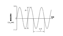
この点を踏まえ、本実施形態の制御装置20は、図4に示すように、こうしたアクティブ転舵制御時には、ステアリング2に付与する操舵反力Fhの値を、その開始時の値(保持値F0)に所定の波動成分を重畳した値とすべく反力アクチュエータ17の作動を制御する(操舵反力波動制御)。そして、これにより、アクティブ転舵制御時に発生する操舵角θsと対応しない路面反力Frに基づく操舵反力Fhの変動を排除するとともに、波動成分の重畳によってステアリング2を揺動させることにより、同アクティブ転舵制御の実行中であることを運転者に知らしめることができるようになっている。   In consideration of this point, as shown in FIG. 4, the control device 20 of the present embodiment sets the value of the steering reaction force Fh to be applied to the steering wheel 2 to the value at the start (holding value F0) during such active steering control. ), The operation of the reaction force actuator 17 is controlled so that a predetermined wave component is superimposed on it (steering reaction force wave control). As a result, the fluctuation of the steering reaction force Fh based on the road surface reaction force Fr that does not correspond to the steering angle θs generated during the active steering control is eliminated, and the steering 2 is swung by the superposition of the wave components, thereby The driver can be informed that the active steering control is being executed.

詳述すると、図2に示すように、本実施形態では、第2ECU24側のマイコン26は、同操舵反力指令演算部41がアクティブ転舵制御の開始時に出力した操舵反力指令Iq*を保持操舵反力指令Iq_s*として記憶し、その保持操舵反力指令Iq_s*を出力する操舵反力指令保持部47と、所定の波動成分としての波動制御量Iq_w*を出力する波動制御量演算部48とを備えている。   More specifically, as shown in FIG. 2, in the present embodiment, the microcomputer 26 on the second ECU 24 side holds the steering reaction force command Iq * output by the steering reaction force command calculation unit 41 at the start of the active steering control. A steering reaction force command holding unit 47 that stores the steering reaction force command Iq_s * and outputs the held steering reaction force command Iq_s *, and a wave control amount calculation unit 48 that outputs a wave control amount Iq_w * as a predetermined wave component. And.

操舵反力指令保持部47には、操舵反力指令演算部41により演算された操舵反力指令Iq*とともに、第1ECU23(アクティブ制御演算部37)の出力するアクティブ転舵信号Saが入力されるようになっており、同操舵反力指令保持部47は、このアクティブ転舵信号Saが「ON」となった時の操舵反力指令Iq*を保持操舵反力指令Iq_s*として記憶する。即ち、操舵反力指令保持部47は、アクティブ転舵制御が開始された時点の操舵反力指令Iq*を保持操舵反力指令Iq_s*として記憶する。そして、操舵反力指令保持部47は、入力されるアクティブ転舵信号Saが「OFF」、即ちアクティブ転舵制御が終了するまでその保持操舵反力指令Iq_s*を出力する。   The steering reaction force command holding unit 47 receives the steering reaction force command Iq * calculated by the steering reaction force command calculation unit 41 and the active steering signal Sa output from the first ECU 23 (active control calculation unit 37). The steering reaction force command holding unit 47 stores the steering reaction force command Iq * when the active steering signal Sa is “ON” as the holding steering reaction force command Iq_s *. That is, the steering reaction force command holding unit 47 stores the steering reaction force command Iq * at the time when the active steering control is started as the holding steering reaction force command Iq_s *. Then, the steering reaction force command holding unit 47 outputs the held steering reaction force command Iq_s * until the input active steering signal Sa is “OFF”, that is, until the active steering control is finished.

一方、本実施形態では、波動制御量演算部48には、路面反力推定演算部43により推定(検出)された路面反力Frの微分値αFrが入力されるようになっている。そして、図5に示すように、波動制御量演算部48は、この入力される路面反力Frの微分値αFr、即ち検出される路面反力Frの変化速度に応じて、その出力する波動制御量Iq_w*の振幅A及び周波数fを変更するようになっている。   On the other hand, in this embodiment, the differential value αFr of the road surface reaction force Fr estimated (detected) by the road surface reaction force estimation calculation unit 43 is input to the wave control amount calculation unit 48. Then, as shown in FIG. 5, the wave control amount calculation unit 48 outputs the wave control according to the differential value αFr of the input road surface reaction force Fr, that is, the change speed of the detected road surface reaction force Fr. The amplitude A and the frequency f of the quantity Iq_w * are changed.

具体的には、本実施形態では、波動制御量演算部48は、路面反力Frの微分値αFrと波動制御量Iq_w*の振幅Aとが関係付けられたマップ48a、及び同微分値αFrと波動制御量Iq_w*の周波数fとが関係付けられたマップ48bを有している(図6(a)(b)参照)。より具体的には、マップ48aにおいて、振幅Aは、微分値αFrが大となるほど小となるように設定されている(約0.2〜0.5Nm)。また、マップ48bにおいて、周波数fは、微分値αFrが大となるほど大となるように設定されている(約5〜20Hz)。そして、波動制御量演算部48は、これらのマップ48a,48bに基づいて、出力する波動制御量Iq_w*の振幅A及び周波数fを決定する。即ち、本実施形態では、波動制御量演算部48は、検出される路面反力Frの変化速度(路面反力Frの微分値αFr)が大きいほど、振幅Aが小さく周波数fの高い波動制御量Iq_w*を出力し、路面反力Frの変化速度(路面反力Frの微分値αFr)が小さいほど、振幅Aが大きく周波数fの低い波動制御量Iq_w*を出力する。   Specifically, in the present embodiment, the wave control amount calculation unit 48 includes the map 48a in which the differential value αFr of the road surface reaction force Fr and the amplitude A of the wave control amount Iq_w * are related, and the differential value αFr. A map 48b is associated with the frequency f of the wave control amount Iq_w * (see FIGS. 6A and 6B). More specifically, in the map 48a, the amplitude A is set so as to decrease as the differential value αFr increases (approximately 0.2 to 0.5 Nm). In the map 48b, the frequency f is set so as to increase as the differential value αFr increases (approximately 5 to 20 Hz). Then, the wave control amount calculation unit 48 determines the amplitude A and the frequency f of the wave control amount Iq_w * to be output based on these maps 48a and 48b. In other words, in the present embodiment, the wave control amount calculation unit 48 increases the wave control amount having a smaller amplitude A and a higher frequency f as the change speed of the detected road surface reaction force Fr (the differential value αFr of the road surface reaction force Fr) is larger. Iq_w * is output, and the wave control amount Iq_w * having a larger amplitude A and a lower frequency f is output as the change speed of the road surface reaction force Fr (the differential value αFr of the road surface reaction force Fr) is smaller.

本実施形態では、波動制御量演算部48の出力する波動制御量Iq_w*は、操舵反力指令保持部47の出力する保持操舵反力指令Iq_s*とともに加算器49に入力され、同加算器49において保持操舵反力指令Iq_s*に重畳される。そして、その重畳後の波動操舵反力指令Iq_s**は、操舵反力指令演算部41の出力する操舵反力指令Iq*、及びアクティブ転舵信号Saとともに、出力切替部50に入力される。そして、出力切替部50は、アクティブ転舵信号Saが「OFF」の場合には、操舵反力指令演算部41が出力する操舵反力指令Iq*をモータ制御信号生成部42に出力し、アクティブ転舵信号Saが「ON」の場合には、保持操舵反力指令Iq_s*に波動制御量Iq_w*が重畳された波動操舵反力指令Iq_s**をモータ制御信号生成部42に出力する。   In the present embodiment, the wave control amount Iq_w * output from the wave control amount calculation unit 48 is input to the adder 49 together with the holding steering reaction force command Iq_s * output from the steering reaction force command holding unit 47. Is superimposed on the holding steering reaction force command Iq_s *. The superposed wave steering reaction force command Iq_s ** is input to the output switching unit 50 together with the steering reaction force command Iq * output from the steering reaction force command calculation unit 41 and the active steering signal Sa. Then, when the active steering signal Sa is “OFF”, the output switching unit 50 outputs the steering reaction force command Iq * output from the steering reaction force command calculation unit 41 to the motor control signal generation unit 42 to be active. When the turning signal Sa is “ON”, the wave steering reaction force command Iq_s ** in which the wave control amount Iq_w * is superimposed on the holding steering reaction force command Iq_s * is output to the motor control signal generation unit 42.

即ち、図7のフローチャートに示すように、マイコン26は、先ず、センサ値(車両状態量)として変位量X、実電流値Is、操舵トルクτ、操舵角θs、及び車速Vを取得し(ステップ101)、続いて路面反力Frの推定(ステップ102)、及びその路面反力Frに応じた操舵反力Fhをステアリングに付与するための操舵反力指令Iq*の演算を実行する(ステップ103)。   That is, as shown in the flowchart of FIG. 7, the microcomputer 26 first obtains the displacement amount X, the actual current value Is, the steering torque τ, the steering angle θs, and the vehicle speed V as sensor values (vehicle state quantities) (steps). 101) Subsequently, the road surface reaction force Fr is estimated (step 102), and the steering reaction force command Iq * for giving the steering reaction force Fh corresponding to the road surface reaction force Fr to the steering is executed (step 103). ).

次に、マイコン26は、第1ECU23側から入力されるアクティブ転舵信号Saが「ON」であるか否か、即ち上記アクティブ転舵制御が「オン」であるか否かを判定する(ステップ104)。そして、その判定が「オン」である場合(Sa=ON、ステップ104:YES)には、続いて操舵反力波動制御が実行されているか否か、即ち既に実行中であるか否かを判定する(ステップ105)。尚、実行中であるか否かの判定は、後述する実行フラグがセットされているか否かにより行われる。そして、マイコン26は、このステップ105において、実行中ではない、即ち操舵反力波動制御の開始時であると判定した場合(ステップ105:NO)には、実行フラグをセットし(ステップ106)、その時点の操舵反力指令Iq*を保持値、即ち保持操舵反力指令Iq_s*として記憶する(ステップ107)。尚、上記ステップ105において、既に実行中であると判定した場合(ステップ105:YES)には、マイコン26は、上記ステップ106,107の処理を実行することなく、以下に示すステップ108以降の処理を実行する。   Next, the microcomputer 26 determines whether or not the active steering signal Sa input from the first ECU 23 side is “ON”, that is, whether or not the active steering control is “ON” (step 104). ). If the determination is “ON” (Sa = ON, Step 104: YES), it is determined whether the steering reaction force wave control is subsequently executed, that is, whether it is already being executed. (Step 105). Whether or not the execution is in progress is determined based on whether or not an execution flag described later is set. If the microcomputer 26 determines in step 105 that the steering reaction force wave control is not being executed (step 105: NO), an execution flag is set (step 106). The steering reaction force command Iq * at that time is stored as a holding value, that is, a holding steering reaction force command Iq_s * (step 107). If it is determined in step 105 that the process is already being executed (step 105: YES), the microcomputer 26 does not execute the processes in steps 106 and 107, but performs the processes in and after step 108 shown below. Execute.

次に、マイコン26は、上記ステップ102において推定(検出)された路面反力Fr、詳しくはその微分値αFrに基づいて、波動成分として、その微分値αFr、即ち路面反力Frの変化速度に応じた振幅A及び周波数fを有する波動制御量Iq_w*を演算する(ステップ108)。そして、この波動制御量Iq_w*を上記ステップ107において記憶された保持値(操舵反力指令Iq*)に重畳し(ステップ109)、その重畳された波動値(波動操舵反力指令Iq_s**)に基づくモータ制御信号を駆動回路28へと出力する(ステップ110)。   Next, the microcomputer 26 uses the road surface reaction force Fr estimated (detected) in the above step 102, more specifically, the differential value αFr as a wave component, to change the differential value αFr, that is, the change speed of the road surface reaction force Fr. A wave control amount Iq_w * having a corresponding amplitude A and frequency f is calculated (step 108). The wave control amount Iq_w * is superimposed on the holding value (steering reaction force command Iq *) stored in step 107 (step 109), and the superimposed wave value (wave steering reaction force command Iq_s **) Is output to the drive circuit 28 (step 110).

一方、上記ステップ104において、ステップ104における判定が「オフ」であると判定した場合(Sa=OFF、ステップ104:NO)、マイコン26は、続いて実行中であるか否かを判定する(ステップ111)。そして、このステップ111において、実行中であると判定した場合(ステップ111:YES)には、実行フラグをリセットし(ステップ112)、上記ステップ103において演算された操舵反力指令Iq*、即ち現在の路面反力Frが反映された現在値に基づくモータ制御信号を駆動回路28に出力する(ステップ113)。尚、上記ステップ111において、実行中ではないと判定した場合(ステップ111:NO)には、上記ステップ112を実行することなく、ステップ113において、現在値(操舵反力指令Iq*)に基づくモータ制御信号を駆動回路28に出力する。   On the other hand, if it is determined in step 104 that the determination in step 104 is “OFF” (Sa = OFF, step 104: NO), the microcomputer 26 subsequently determines whether or not the execution is in progress (step 111). If it is determined in step 111 that the process is being executed (step 111: YES), the execution flag is reset (step 112), and the steering reaction force command Iq * calculated in step 103, that is, the current A motor control signal based on the current value reflecting the road surface reaction force Fr is output to the drive circuit 28 (step 113). If it is determined in step 111 that the motor is not being executed (step 111: NO), the motor based on the current value (steering reaction force command Iq *) is not executed in step 113 without executing step 112. A control signal is output to the drive circuit 28.

こうした上記一連の処理によって、通常時(非アクティブ転舵制御時)には、操舵反力指令演算部41の出力する操舵反力指令Iq*に基づく駆動電力がモータ18に供給され、これにより、現在の路面反力Frが反映された操舵反力Fhがステアリング2に付与される。また、アクティブ転舵制御時には、操舵反力指令保持部47の出力する保持操舵反力指令Iq_s*に波動制御量演算部48の出力する波動制御量Iq_w*が重畳された波動操舵反力指令Iq_s**に基づく駆動電力がモータ18に供給される。そして、これにより同アクティブ転舵制御の開始時点の値に所定の波動成分が重畳された値を有する操舵反力Fhがステアリング2に付与されるようになっている。   Through the series of processes described above, during normal operation (during inactive steering control), drive power based on the steering reaction force command Iq * output from the steering reaction force command calculation unit 41 is supplied to the motor 18, thereby A steering reaction force Fh reflecting the current road surface reaction force Fr is applied to the steering 2. In active steering control, the wave steering reaction force command Iq_s in which the wave control amount Iq_w * output from the wave control amount calculation unit 48 is superimposed on the holding steering reaction force command Iq_s * output from the steering reaction force command holding unit 47. Drive power based on ** is supplied to the motor 18. As a result, a steering reaction force Fh having a value obtained by superimposing a predetermined wave component on the value at the start of the active steering control is applied to the steering 2.

以上、本実施形態によれば、以下のような特徴を得ることができる。
(1)制御装置20は、アクティブ転舵制御時には、ステアリング2に付与する操舵反力Fhの値を、その開始時の値(保持値F0)に所定の波動成分を重畳した値とすべく反力アクチュエータ17の作動を制御する(操舵反力波動制御)。このような構成とすれば、アクティブ転舵制御時に発生する操舵角θsと対応しない路面反力Frに基づく操舵反力Fhの変動を排除して良好な操舵フィーリングを確保することができる。また、波動成分の重畳によってステアリングが揺動することにより、同アクティブ転舵制御の実行中であることをより確実に運転者に知らしめることができる。従って、例えば、カウンタステア時等、アクティブ転舵制御によって、車両が運転者の想定と異なる挙動を示すような場合であっても、運転者は、その挙動がアクティブ転舵制御によるものであることを認識することができ、これにより、アクティブ転舵制御と逆行するステアリング操作の発生を未然に防止することができる。その結果、こうしたアクティブ転舵制御と逆行するステアリング操作によるアクティブ転舵制御の有効性低下やアクティブ転舵制御の終了遅れ等を効果的に抑制することができるようになる。
As described above, according to the present embodiment, the following features can be obtained.
(1) At the time of active steering control, the control device 20 reacts so that the value of the steering reaction force Fh applied to the steering wheel 2 is a value obtained by superimposing a predetermined wave component on the starting value (holding value F0). The operation of the force actuator 17 is controlled (steering reaction force wave control). With such a configuration, it is possible to ensure a good steering feeling by eliminating the fluctuation of the steering reaction force Fh based on the road surface reaction force Fr that does not correspond to the steering angle θs generated during the active steering control. In addition, since the steering is swung by the superposition of the wave component, the driver can be more surely informed that the active steering control is being executed. Therefore, for example, even when the vehicle exhibits a behavior different from the driver's assumption due to active steering control, such as during counter-steering, the driver must have the behavior due to active steering control. Thus, it is possible to prevent the occurrence of a steering operation reverse to the active steering control. As a result, it is possible to effectively suppress a decrease in the effectiveness of the active steering control due to a steering operation that goes against the active steering control, a delay in the end of the active steering control, and the like.

(2)波動制御量演算部48は、入力される路面反力Frの微分値αFr、即ち検出される路面反力Frの変化速度に応じて、その出力する波動成分としての波動制御量Iq_w*の振幅A及び周波数fを変更する。このような構成とすれば、実行中のアクティブ転舵制御の状態を、効果的に運転者に告知することができ、運転者にさらなる安心感を与えることが可能になる。特に、本実施形態では、波動制御量演算部48は、検出される路面反力Frの変化速度(路面反力Frの微分値αFr)が大きいほど、振幅Aが小さく周波数fの高い波動制御量Iq_w*を出力し、路面反力Frの変化速度(路面反力Frの微分値αFr)が小さいほど、振幅Aが大きく周波数fの低い波動制御量Iq_w*を出力する。従って、アクティブ制御量が大きな場合には、振幅Aが小さく周波数fが高くなるため、それによってステアリングがとられることもない。   (2) The wave control amount calculation unit 48 determines the wave control amount Iq_w * as the wave component to be output in accordance with the differential value αFr of the input road surface reaction force Fr, that is, the change speed of the detected road surface reaction force Fr. Are changed in amplitude A and frequency f. With such a configuration, it is possible to effectively notify the driver of the state of the active steering control that is being executed, and it is possible to give the driver a further sense of security. In particular, in the present embodiment, the wave control amount calculation unit 48 increases the wave control amount having a smaller amplitude A and a higher frequency f as the change speed of the detected road surface reaction force Fr (the differential value αFr of the road surface reaction force Fr) is larger. Iq_w * is output, and the wave control amount Iq_w * having a larger amplitude A and a lower frequency f is output as the change speed of the road surface reaction force Fr (the differential value αFr of the road surface reaction force Fr) is smaller. Therefore, when the amount of active control is large, the amplitude A is small and the frequency f is high, so that steering is not taken.

なお、本実施形態は以下のように変更してもよい。
・本実施形態では、制御手段としての制御装置20は、転舵アクチュエータ8を制御するための第1ECU23と、反力アクチュエータ17を制御するための第2ECU24とを備えることとした。しかし、これに限らず、転舵アクチュエータ8及び反力アクチュエータ17を制御する制御手段は、第1ECU23及び第2ECU24に相当するものが各々別体に設けられた構成であってもよい。
In addition, you may change this embodiment as follows.
In the present embodiment, the control device 20 as the control means includes a first ECU 23 for controlling the steering actuator 8 and a second ECU 24 for controlling the reaction force actuator 17. However, the present invention is not limited to this, and the control means for controlling the steered actuator 8 and the reaction force actuator 17 may have a configuration in which components corresponding to the first ECU 23 and the second ECU 24 are provided separately.

・本実施形態では、制御装置20は、検出された操舵角θs、車速V及び変位量Xに基づいて、転舵輪4の転舵角θtを変更すべく転舵アクチュエータ8の作動を制御することとした。しかし、これに限らず、転舵アクチュエータ8は、少なくとも操舵角θsに基づいて制御されるものであればよい。また、制御装置20は、操舵トルクτ及び車速V(並びに路面反力Fr)に基づいて、操舵反力を付与すべく反力アクチュエータ17の作動を制御することとしたが、路面反力Frに応じた操舵反力を付与可能なものであれば、路面反力Fr以外のパラメータは、操舵トルクτ及び車速Vに限るものではない。   In the present embodiment, the control device 20 controls the operation of the steered actuator 8 to change the steered angle θt of the steered wheels 4 based on the detected steering angle θs, vehicle speed V, and displacement amount X. It was. However, the present invention is not limited to this, and the steered actuator 8 only needs to be controlled based on at least the steering angle θs. The control device 20 controls the operation of the reaction force actuator 17 to apply the steering reaction force based on the steering torque τ and the vehicle speed V (and the road surface reaction force Fr). The parameters other than the road surface reaction force Fr are not limited to the steering torque τ and the vehicle speed V as long as a corresponding steering reaction force can be applied.

・本実施形態では、路面反力推定演算部43は、変位量センサ22により検出された変位量X及び転舵アクチュエータ8の駆動源であるモータ13の実電流値に基づいて転舵軸12に作用する軸力を演算し、その軸力を転舵輪4に作用する路面反力Frと推定することとした。しかし、これに限らず、路面反力Frの推定には、位置制御演算部32により算出された位置制御量εを用いる構成としてもよい。   In the present embodiment, the road surface reaction force estimation calculation unit 43 applies the turning shaft 12 to the turning shaft 12 based on the displacement amount X detected by the displacement amount sensor 22 and the actual current value of the motor 13 that is the drive source of the turning actuator 8. The acting axial force is calculated, and the axial force is estimated as the road surface reaction force Fr acting on the steered wheels 4. However, the present invention is not limited to this, and the road surface reaction force Fr may be estimated using the position control amount ε calculated by the position control calculation unit 32.

・また、制御装置20は、推定された路面反力Frを用いて反力アクチュエータの作動を制御することとしたが、路面反力Frは、歪みゲージ等を用いて転舵軸12に作用する軸力を検出する等、路面反力Frを直接的に検出する構成としてもよい。   Further, the control device 20 controls the operation of the reaction force actuator using the estimated road surface reaction force Fr, but the road surface reaction force Fr acts on the steered shaft 12 using a strain gauge or the like. A configuration may be adopted in which the road surface reaction force Fr is directly detected, such as detecting an axial force.

・また、変位量Xは、必ずしも変位量センサ22により検出することはなく、回転角センサ35により検出されるモータ13の回転角から推定する構成としてもよい。
・本実施形態では、波動制御量演算部48は、検出される路面反力Frの変化速度(路面反力Frの微分値αFr)が大きいほど、振幅Aが小さく周波数fの高い波動制御量Iq_w*を出力し、路面反力Frの変化速度(路面反力Frの微分値αFr)が小さいほど、振幅Aが大きく周波数fの低い波動制御量Iq_w*を出力することとした。しかし、これに限らず、路面反力Frの変化速度に応じて振幅A又は周波数fの一方を変更する構成としてもよい。即ち振幅A又は周波数fの少なくとも何れかを変更する構成であってもよい。また、路面反力Frの変化速度が大きいほど振幅Aを大きくする、或いは周波数fを低くする等、その変更する形態はどのようなものであってもよい。
In addition, the displacement amount X is not necessarily detected by the displacement amount sensor 22 and may be estimated from the rotation angle of the motor 13 detected by the rotation angle sensor 35.
In this embodiment, the wave control amount calculation unit 48 increases the wave control amount Iq_w having a smaller amplitude A and a higher frequency f as the change speed of the detected road surface reaction force Fr (the differential value αFr of the road surface reaction force Fr) is larger. * Is output, and as the change speed of the road surface reaction force Fr (the differential value αFr of the road surface reaction force Fr) is smaller, the wave control amount Iq_w * having a larger amplitude A and a lower frequency f is output. However, the present invention is not limited to this, and one of the amplitude A and the frequency f may be changed according to the changing speed of the road surface reaction force Fr. That is, it may be configured to change at least one of the amplitude A and the frequency f. Further, any change may be made, such as increasing the amplitude A or decreasing the frequency f as the change speed of the road surface reaction force Fr increases.

・本実施形態では、振幅Aの変更幅を約0.2〜0.5Nmとし、周波数fの変更幅を約5〜20Hzとした。しかし、これに限らず、周波数fの変更幅を100Hz程度まで拡張する等、これら振幅A又は周波数fの変更幅は、任意に設定してもよい。   In this embodiment, the change width of the amplitude A is about 0.2 to 0.5 Nm, and the change width of the frequency f is about 5 to 20 Hz. However, the present invention is not limited to this, and the change width of the amplitude A or the frequency f may be arbitrarily set, such as extending the change width of the frequency f to about 100 Hz.

・本実施形態では、本発明を所謂ステアバイワイヤ式の車両用操舵装置に具体化したが、これに限らず、反力アクチュエータを備えたものであれば、ステアリングと転舵輪が機械的に連結されたもの、例えば、伝達比可変装置付きの車両用操舵装置等に具体化してもよい。   In the present embodiment, the present invention is embodied in a so-called steer-by-wire vehicle steering apparatus. However, the present invention is not limited thereto, and the steering wheel and the steered wheels are mechanically connected as long as the reaction force actuator is provided. For example, the present invention may be embodied in a vehicle steering device with a variable transmission ratio device.

ステアリング装置の概略構成図。The schematic block diagram of a steering device. ステアリング装置の制御ブロック図。The control block diagram of a steering device. アクティブ転舵制御時に路面反力を反映させた場合の操舵反力の変化を示す波形図。The wave form diagram which shows the change of steering reaction force at the time of reflecting road surface reaction force at the time of active steering control. 操舵反力波動制御を行った場合の操舵反力の変化を示す波形図。The wave form diagram which shows the change of steering reaction force at the time of performing steering reaction force wave control. 波動成分として重畳される波動制御量の波形図。The wave form diagram of the wave control amount superimposed as a wave component. (a)(b)マップの概略構成図。(A) (b) The schematic block diagram of a map. 操舵反力波動制御の処理手順を示すフローチャート。The flowchart which shows the process sequence of steering reaction force wave control.

符号の説明Explanation of symbols

1…ステアリング装置、2…ステアリング(ハンドル)、3…操舵機構、4…転舵輪、5…転舵機構、6…ステアリングシャフト、7…操舵角センサ、8…転舵アクチュエータ、12…転舵軸、16…トルクセンサ、17…反力アクチュエータ、20…制御装置、21…車速センサ、22…変位量センサ、23…第1ECU、24…第2ECU、25,26…マイコン、31…変位量指令演算部、50…出力切替部、γ…車両状態量、θs…操舵角、θt…転舵角、τ…操舵トルク、V…車速、X…変位量、X*…変位量指令、Xn*…通常制御目標量、Xa*…アクティブ制御目標量、ε…位置制御量、Fr…路面反力、αFr…微分値、Fh…操舵反力、Sa…アクティブ転舵信号、Iq*…操舵反力指令、Iq_s*…保持操舵反力指令、Iq_w*…波動制御量、Iq_s**…波動操舵反力指令、A…振幅、f…周波数。   DESCRIPTION OF SYMBOLS 1 ... Steering device, 2 ... Steering (handle), 3 ... Steering mechanism, 4 ... Steering wheel, 5 ... Steering mechanism, 6 ... Steering shaft, 7 ... Steering angle sensor, 8 ... Steering actuator, 12 ... Steering shaft , 16 ... torque sensor, 17 ... reaction force actuator, 20 ... control device, 21 ... vehicle speed sensor, 22 ... displacement sensor, 23 ... first ECU, 24 ... second ECU, 25, 26 ... microcomputer, 31 ... displacement amount command calculation 50, output switching unit, γ ... vehicle state quantity, θs ... steering angle, θt ... steering angle, τ ... steering torque, V ... vehicle speed, X ... displacement quantity, X * ... displacement quantity command, Xn * ... normal Control target amount, Xa *: Active control target amount, ε: Position control amount, Fr: Road reaction force, αFr: Differential value, Fh: Steering reaction force, Sa: Active steering signal, Iq *: Steering reaction force command, Iq_s *: Holding steering reaction force command, Iq_w *: Wave control amount, Iq_s * * ... Wave steering reaction force command, A ... Amplitude, f ... Frequency.

Claims (4)

転舵輪と機械的に分離されたステアリングと、ステアリング操作に応じた前記転舵輪の転舵角を発生させるべく制御される転舵アクチュエータと、前記転舵輪に作用する路面反力を検出する路面反力検出手段と、前記検出される路面反力に応じた操舵反力を前記ステアリングに付与すべく制御される反力アクチュエータと、前記転舵アクチュエータ及び反力アクチュエータの作動を制御する制御手段とを備え、前記制御手段は、ステアリング操作によらず自動的に前記転舵角を変更すべく前記転舵アクチュエータの作動を制御するアクティブ転舵制御機能を有する車両用操舵装置であって、
前記制御手段は、前記アクティブ転舵制御時には、前記ステアリングに付与する操舵反力をアクティブ転舵制御の開始時の値に所定の波動成分を重畳した値とすべく前記反力アクチュエータの作動を制御すること、を特徴とする車両用操舵装置。
Steering mechanically separated from the steered wheels, a steered actuator that is controlled to generate a steered angle of the steered wheels according to steering operation, and a road surface reaction that detects a road reaction force acting on the steered wheels Force detection means, reaction force actuators controlled to give a steering reaction force corresponding to the detected road surface reaction force to the steering, and control means for controlling the operation of the steering actuator and the reaction force actuator And the control means is a vehicle steering apparatus having an active steering control function for controlling the operation of the steering actuator to automatically change the steering angle irrespective of a steering operation,
The control means controls the operation of the reaction force actuator so that a steering reaction force applied to the steering is a value obtained by superimposing a predetermined wave component on a value at the start of the active steering control during the active steering control. A vehicle steering apparatus characterized by that.
請求項1に記載の車両用操舵装置において、
前記制御手段は、前記検出される路面反力の変化速度に応じて、前記波動成分の振幅又は周波数の少なくとも一方を変更すること、を特徴とする車両用操舵装置。
The vehicle steering apparatus according to claim 1,
The vehicle steering apparatus according to claim 1, wherein the control means changes at least one of an amplitude and a frequency of the wave component in accordance with the detected change speed of the road surface reaction force.
請求項2に記載の車両用操舵装置において、
前記制御手段は、前記検出される路面反力の変化速度が大であるほど、前記振幅を小とすること、を特徴とする車両用操舵装置。
The vehicle steering apparatus according to claim 2,
The vehicle steering apparatus according to claim 1, wherein the control means decreases the amplitude as the change speed of the detected road surface reaction force increases.
請求項2又は請求項3に記載の車両用操舵装置において、
前記制御手段は、前記検出される路面反力の変化速度が大であるほど、前記周波数を大とすること、を特徴とする車両用操舵装置。
In the vehicle steering apparatus according to claim 2 or 3,
The vehicle steering apparatus, wherein the control means increases the frequency as the change speed of the detected road surface reaction force increases.
JP2005057613A 2005-03-02 2005-03-02 Vehicle steering system Expired - Fee Related JP4635648B2 (en)

Priority Applications (1)

Application Number Priority Date Filing Date Title
JP2005057613A JP4635648B2 (en) 2005-03-02 2005-03-02 Vehicle steering system

Applications Claiming Priority (1)

Application Number Priority Date Filing Date Title
JP2005057613A JP4635648B2 (en) 2005-03-02 2005-03-02 Vehicle steering system

Publications (2)

Publication Number Publication Date
JP2006240440A JP2006240440A (en) 2006-09-14
JP4635648B2 true JP4635648B2 (en) 2011-02-23

Family

ID=37047271

Family Applications (1)

Application Number Title Priority Date Filing Date
JP2005057613A Expired - Fee Related JP4635648B2 (en) 2005-03-02 2005-03-02 Vehicle steering system

Country Status (1)

Country Link
JP (1) JP4635648B2 (en)

Families Citing this family (1)

* Cited by examiner, † Cited by third party
Publication number Priority date Publication date Assignee Title
JP5853589B2 (en) * 2011-10-26 2016-02-09 日産自動車株式会社 Driving assistance device

Family Cites Families (7)

* Cited by examiner, † Cited by third party
Publication number Priority date Publication date Assignee Title
JPH0577751A (en) * 1991-09-17 1993-03-30 Fuji Heavy Ind Ltd Steering control device for vehicle
JP2004182008A (en) * 2002-11-29 2004-07-02 Toyoda Mach Works Ltd Steering control system of vehicle and steering system control method
JP3689403B2 (en) * 2002-12-12 2005-08-31 三菱電機株式会社 Vehicle steering system
JP4283550B2 (en) * 2003-01-24 2009-06-24 本田技研工業株式会社 Steering device
JP4120427B2 (en) * 2003-03-06 2008-07-16 トヨタ自動車株式会社 Steering control device for vehicle
JP4193576B2 (en) * 2003-05-14 2008-12-10 トヨタ自動車株式会社 Vehicle steering system
JP4294401B2 (en) * 2003-07-25 2009-07-15 富士重工業株式会社 Vehicle travel support device

Also Published As

Publication number Publication date
JP2006240440A (en) 2006-09-14

Similar Documents

Publication Publication Date Title
CN109963766B (en) Control steer-by-wire type steering system
EP2492168A1 (en) Electric power steering device for vehicle
WO2019171447A1 (en) Vehicle steering control method and vehicle steering control device
JP2009023542A (en) Vehicle steering system
JP4997478B2 (en) Vehicle steering system
JP4617946B2 (en) Vehicle steering system
JP5181563B2 (en) Vehicle steering system
JP7200981B2 (en) POWER STEERING CONTROL DEVICE AND POWER STEERING CONTROL METHOD
JP7307000B2 (en) steering controller
JP7404027B2 (en) Steering control device
JP4826347B2 (en) Vehicle steering device
JP2014184745A (en) Steering control device
JP5546431B2 (en) Electric power steering device
JP6634872B2 (en) Vehicle control device
JP2009101885A (en) Transmission ratio variable device
JP4635648B2 (en) Vehicle steering system
JP2010188909A (en) Electric power steering device
JP2008254521A (en) Steering device
JP4635661B2 (en) Vehicle steering system
WO2013132807A1 (en) Vehicle steering controller and vehicle steering control method
JP4978347B2 (en) Vehicle steering system
JP2005059645A (en) Blinker cancellation device in steer-by-wire steering system
JP4604840B2 (en) Vehicle steering system
JP5012314B2 (en) Vehicle steering system
JP4586551B2 (en) Vehicle steering system

Legal Events

Date Code Title Description
A621 Written request for application examination

Free format text: JAPANESE INTERMEDIATE CODE: A621

Effective date: 20080212

A977 Report on retrieval

Free format text: JAPANESE INTERMEDIATE CODE: A971007

Effective date: 20091217

A131 Notification of reasons for refusal

Free format text: JAPANESE INTERMEDIATE CODE: A131

Effective date: 20100720

A521 Request for written amendment filed

Free format text: JAPANESE INTERMEDIATE CODE: A523

Effective date: 20100917

TRDD Decision of grant or rejection written
A01 Written decision to grant a patent or to grant a registration (utility model)

Free format text: JAPANESE INTERMEDIATE CODE: A01

Effective date: 20101026

A01 Written decision to grant a patent or to grant a registration (utility model)

Free format text: JAPANESE INTERMEDIATE CODE: A01

A61 First payment of annual fees (during grant procedure)

Free format text: JAPANESE INTERMEDIATE CODE: A61

Effective date: 20101108

FPAY Renewal fee payment (event date is renewal date of database)

Free format text: PAYMENT UNTIL: 20131203

Year of fee payment: 3

R150 Certificate of patent or registration of utility model

Ref document number: 4635648

Country of ref document: JP

Free format text: JAPANESE INTERMEDIATE CODE: R150

Free format text: JAPANESE INTERMEDIATE CODE: R150

LAPS Cancellation because of no payment of annual fees