JP4635643B2 - Deposition boat and sheath thermocouple - Google Patents
Deposition boat and sheath thermocouple Download PDFInfo
- Publication number
- JP4635643B2 JP4635643B2 JP2005052660A JP2005052660A JP4635643B2 JP 4635643 B2 JP4635643 B2 JP 4635643B2 JP 2005052660 A JP2005052660 A JP 2005052660A JP 2005052660 A JP2005052660 A JP 2005052660A JP 4635643 B2 JP4635643 B2 JP 4635643B2
- Authority
- JP
- Japan
- Prior art keywords
- vapor deposition
- deposition boat
- boat
- plate
- container
- Prior art date
- Legal status (The legal status is an assumption and is not a legal conclusion. Google has not performed a legal analysis and makes no representation as to the accuracy of the status listed.)
- Expired - Fee Related
Links
Images


Landscapes
- Physical Vapour Deposition (AREA)
Description
本発明は蒸着材料を抵抗加熱蒸着する際に用いられる昇華性材料用蒸着ボートおよび蒸着ボート温度測定用シース熱電対に関するものである。 The present invention relates to a vapor deposition boat for a sublimable material and a sheathed thermocouple for vapor deposition boat temperature measurement used when vapor deposition material is subjected to resistance heating vapor deposition.
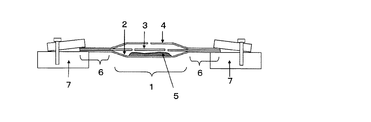
近年、有機デバイスの研究開発が盛んになり、機能性の有機薄膜が用いられている。蒸着に用いる有機材料は昇華性または溶融蒸発性の材料がある。実験室レベルでの簡易的な小型蒸着装置では多くの場合、どちらのタイプの材料を蒸着する場合でも図5に示すような昇華性材料用蒸着ボートが用いられてきた。 In recent years, research and development of organic devices has become active, and functional organic thin films have been used. Organic materials used for vapor deposition include sublimation or melt evaporation materials. In many cases, a simple small vapor deposition apparatus at a laboratory level has used a vapor deposition boat for a sublimable material as shown in FIG. 5 for depositing either type of material.
有機EL素子においてホスト材料とドーパント発光材料を共蒸着するような場合においてはホスト材料中のドーパント濃度を少なくとも0.1%以下の濃度で制御する必要があるため、蒸着ボートの精密な温度制御が要求されていた。 In the case where the host material and the dopant light-emitting material are co-evaporated in the organic EL element, it is necessary to control the dopant concentration in the host material at a concentration of at least 0.1%. It was requested.
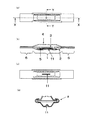
代表的な昇華性材料用蒸着ボートの形状の例は図5(a)、図5(b)、図6に示した。これらは蒸着材料を入れる容器部(1)を有する底板(2)、2穴またはメッシュ状の穴の開いた中板(3)、直径1mm程度の穴の開いたカバー(4)を順に重ね合わせた構造になっている。蒸着ボートの材質はタンタル、タングステン、モリブデン、ニオブ等から選ばれた高融点金属が従来使われている。 The example of the shape of the vapor deposition boat for typical sublimation materials was shown to Fig.5 (a), FIG.5 (b), and FIG. They are composed of a bottom plate (2) having a container part (1) for storing a vapor deposition material, a middle plate (3) with two holes or mesh holes, and a cover (4) with a hole having a diameter of about 1 mm. It has a structure. As a material for the evaporation boat, a refractory metal selected from tantalum, tungsten, molybdenum, niobium and the like has been used.
これらの蒸着ボートは、図6で示すように蒸着材料(5)を入れる長さ3から4cm、幅9mmから16mm、深さ3から5mm程度の容器部(1)の両側に、平板上の長さ3cm程度の電極板部(6)が付いた構造で、銅製の電極ジグ(7)で挟み通電され加熱される。底板には、容器部の長さより数mm長く、かつ数mm程度幅広い金属板を30から60度程度の角度に折り返したガイド部(8)が両脇に作られている。底板上に、中板とカバーをガイド部に差し込み、さらにガイド部を折り込むことにより底板に中板とカバーを挟み込み、図5(b)のように密着させることができるようになっている。 As shown in FIG. 6, these vapor deposition boats are provided on both sides of a container portion (1) having a length of 3 to 4 cm, a width of 9 mm to 16 mm, and a depth of 3 to 5 mm. It has a structure with an electrode plate part (6) of about 3 cm in length, and is energized and heated between copper electrode jigs (7). On the bottom plate, guide portions (8) are formed on both sides by folding back a metal plate several mm longer than the length of the container and several mm wide at an angle of about 30 to 60 degrees. On the bottom plate, the middle plate and the cover are inserted into the guide portion, and the guide portion is further folded so that the middle plate and the cover are sandwiched between the bottom plates and can be brought into close contact as shown in FIG.
昇華性材料は蒸着ボートの温度が少しでも高すぎる場合は急激に昇華し大きな粒が噴出する場合があり、また溶融蒸発性の材料は突沸し材料が飛び出す場合がある。急激な昇華や突沸が起き難い材料の場合は中板(3)を省略し、底板(2)とカバー(4)のみを重ねて使用することも可能であるが、通常は昇華性材料を蒸着する場合には、底板(2)、中板(3)、カバー(4)を重ねあわせ、中板(3)とカバー(4)が邪魔板として働き大きな粒の噴出を抑制している。 If the temperature of the vapor deposition boat is too high, the sublimable material may sublime rapidly and large particles may be ejected, and the melt-evaporable material may bump and the material may jump out. In the case of materials that do not easily undergo sublimation or bumping, it is possible to omit the middle plate (3) and use only the bottom plate (2) and cover (4), but usually a sublimable material is deposited. When doing so, the bottom plate (2), the middle plate (3), and the cover (4) are overlapped, and the middle plate (3) and the cover (4) act as a baffle plate to suppress ejection of large particles.
しかし、温度制御が十分でない場合は大きな粒の噴出を完全に防ぐことはできず蒸着膜中に大きな粒が入り欠陥が生じる問題があった。また、蒸着ボートの容器部(1)の中央の温度より、熱が逃げる電極板部(6)に近い端の部分の温度は低くなり、電極板部に近い部分に蒸着材料が残り易い問題があり、容器部の温度の均一化が課題となっていた。 However, when the temperature control is not sufficient, the ejection of large grains cannot be completely prevented, and there is a problem that large grains enter into the deposited film and defects occur. Moreover, the temperature of the edge part near the electrode plate part (6) from which heat escapes is lower than the temperature at the center of the container part (1) of the vapor deposition boat, and the vapor deposition material tends to remain in the part near the electrode plate part. There was a problem of uniform temperature of the container part.
従来、昇華性材料用蒸着ボートの温度を熱電対で測定する場合には底板、中板、カバーの各金属板が3枚重なった電極板部の間に細いシース熱電対(9)または先端を絶縁被覆した熱電対の素線からなる温度センサーを図7(a)のように差し込み温度を測定していた。しかし、蒸着ボートの容器部の中心付近でないために容器部の温度より低い温度を測定する問題があったり、また差し込む位置がずれやすく温度を再現性良く制御することが難い問題があった。 Conventionally, when measuring the temperature of a vapor deposition boat for sublimable materials with a thermocouple, a thin sheath thermocouple (9) or tip is placed between the electrode plates where three metal plates of the bottom plate, the middle plate, and the cover overlap. A temperature sensor made of a thermocouple element wire with insulation coating was inserted as shown in FIG. However, since it is not near the center of the container part of the vapor deposition boat, there is a problem of measuring a temperature lower than the temperature of the container part, and there is a problem that it is difficult to control the temperature with good reproducibility because the insertion position tends to shift.
また熱電対は蒸着装置内のアース電位となっている内部ジグと接触した場合、熱電対を通して電流が流れ熱電対がジュール熱により加熱し正確な温度を示さない場合もあった。
昇華性材料用蒸着ボートの容器部の中心の温度を測定するためには直径が1mmより太い剛性のある棒状のシース熱電対またはシース測温抵抗体をバネでボートの底に押し付ける図7(b)のような熱電対押し付け装置(10)が必要になり、真空チャンバーの直径が30cm程度の小型の蒸着装置に取り付けるにはスペース的に問題があった。また、ボートの底と点接触になるため熱電対または測温抵抗体に熱が伝わり難く、かつ強度のある太い棒状熱電対を用いると熱電対の熱容量が大きく正確な温度を短時間で測れない問題があり、できるだけゆっくり温度を制御する必要があった。また熱電対押し付け装置に蒸着物が大量に付着し掃除にも不便であった。
In addition, when the thermocouple comes into contact with the internal jig at the ground potential in the vapor deposition apparatus, a current flows through the thermocouple, and the thermocouple is heated by Joule heat, and sometimes does not show an accurate temperature.
In order to measure the temperature at the center of the vessel portion of the vapor deposition boat for sublimable materials, a rod-shaped sheathed thermocouple having a diameter larger than 1 mm or a sheathed resistance thermometer is pressed against the bottom of the boat with a spring. ) And a thermocouple pressing device (10) as described above is required, and there is a problem in terms of space in attaching to a small vapor deposition device having a vacuum chamber diameter of about 30 cm. In addition, because it is in point contact with the bottom of the boat, it is difficult for heat to be transferred to the thermocouple or resistance thermometer, and if a thick, thick rod-shaped thermocouple is used, the thermocouple has a large heat capacity and it is not possible to measure the exact temperature in a short time. There was a problem and it was necessary to control the temperature as slowly as possible. In addition, a large amount of deposits adhered to the thermocouple pressing device, which was inconvenient for cleaning.
特許文献1においては大量の有機物を仕込む必要がある大型蒸着装置用に昇華性材料用蒸着ボートの底板に相当するバイアスヒーターをタンタル板を溶接し作製している。その容器部内に、容器部の深さよりも背の高い蒸着用有機材料を入れる絶縁容器を挿入し、中板またはカバーにあたる気化ヒーターを被せ、絶縁容器で電気的に分離されたバイアスヒーターと気化ヒーターを別々の電源を用いて加熱し温度制御を行っている。
In
この際、バイアスヒータの温度は光学式高温計または熱電対で測定すると記載されているが、具体的な熱電対取り付け方法の記載は無かった。またこの方法は絶縁容器内の有機物の温度に比べ外側のバイアスヒーターの方が高温になり、さらに絶縁容器の大きな熱容量のために急速な昇温降温や応答速度の速い温度制御をすることは困難と予想された。また、従来のタンタル、タングステン、モリブデン、ニオブ等の昇華性材料用蒸着ボートに用いられてきた高融点金属材料は高価であるという問題もあった。
本発明は簡便な方法で温度を正確に測定し制御できる昇華性材料用蒸着ボートを提供すること、さらにはその蒸着ボートと温度測定用のシース熱電対を用い簡便で再現性良く精度の高い温度制御を低コストで可能にすることを課題としたものである。 The present invention provides a vapor deposition boat for sublimable materials capable of accurately measuring and controlling the temperature by a simple method, and further, using the vapor deposition boat and a sheath thermocouple for temperature measurement, a simple, highly reproducible and accurate temperature. The object is to enable control at low cost.
本発明において上記課題を解決するために、まず請求項1に係る発明は、蒸着材料を入れる容器部を有する底板と、少なくとも穴の開いた中板または穴の開いたカバーの一方を備えた抵抗加熱式金属製昇華性材料用蒸着ボートにおいて、前記底板の蒸着材料が入る容器部の底部の外側に温度センサーを接触、保持するための金属バンドを有する蒸着ボートとした。
In order to solve the above problems in the present invention, the invention is first described in
また、請求項2に係る発明は前記蒸着ボートにおいて、前記底板の容器部の底部が少なくとも1つ以上の線状溝部を有する請求項1記載の蒸着ボートとした。
The invention according to
また、請求項3に係る発明は前記線状溝部が、容器部の底部の中心から20mm以内の場所を含み、且つ、深さ0.3mm以上1.0mm以下、長さ5mm以上30mm以下、幅0.3mm以上3.0mm以下であることを特徴とする請求項2記載の蒸着ボートとした。
In the invention according to
また、請求項4に係る発明は前記蒸着ボートの電極板部と容器部を含む底板がタンタル、モリブデン、ニオブ、ニッケルから選ばれた純度99質量%以上かつ炭素濃度0.02質量%以下の金属板であって、プレス加工により一体で製造されたことを特徴とする請求項1乃至3のいずれかに記載の蒸着ボートとした。
The invention according to
また、請求項5に係る発明は前記蒸着ボートの電極板部と容器部を含む底板がランクフォード値2以上かつ炭素濃度0.01質量%以下のステンレス板をプレス加工により一体で作られたことを特徴とする請求項1乃至3のいずれかに記載の昇華性材料用蒸着ボートとした。
Further, in the invention according to
また、請求項6に係る発明は前記金属バンドが、幅5mm以上25mm以下であり、厚さが0.03mm以上0.3mmであって、前記蒸着ボート容器底部の外側にある温度センサーを包み込むように配置し、金属バンド端部を蒸着ボートの底板のガイド部に固定したことを特徴とする請求項1乃至5のいずれかに記載の蒸着ボートとした。
According to a sixth aspect of the present invention, the metal band has a width of 5 mm or more and 25 mm or less, a thickness of 0.03 mm or more and 0.3 mm, and encloses a temperature sensor outside the bottom of the vapor deposition boat container. placed, and the deposition boat according to claim 1 to 5, wherein the fixed metal band end on the guide portion of the bottom plate of metallization boats.
また、請求項7に係る発明は前記温度センサーがシース熱電対であって、シース長10cm以上2m以下であって、前記蒸着ボートと接触する感熱部を除いた部分を耐熱樹脂により絶縁保護した請求項1乃至6のいずれかに記載の蒸着ボート用シース熱電対とした。
According to a seventh aspect of the present invention, the temperature sensor is a sheath thermocouple, and the sheath length is 10 cm or more and 2 m or less, and a portion excluding the heat sensitive portion that contacts the vapor deposition boat is insulated and protected by a heat resistant resin.
本発明の蒸着ボートを用いて、温度センサーを接触・保持させる保持機構を設けることにより、蒸着ボートの温度を制御することが可能となり、また、本発明の金属板を用いることによって容器部の温度をより均一化することが可能となった。以上より、蒸着ボートの設定温度をオーバーシュートすることがなく、また、蒸着物の突沸や分解を起こすことなく、安定な速度で蒸着することができた。したがって、有機ELデバイスや有機半導体デバイス用等の欠陥の少ない成膜やドープ濃度が一定の共蒸着膜の成膜に有用となった。また、本発明の蒸着ボートを低コストで手に入れることが可能となった。 By using the vapor deposition boat of the present invention, it is possible to control the temperature of the vapor deposition boat by providing a holding mechanism for contacting and holding the temperature sensor, and by using the metal plate of the present invention, the temperature of the container portion can be controlled. Can be made more uniform. From the above, it was possible to deposit at a stable rate without overshooting the set temperature of the deposition boat and without causing bumping and decomposition of the deposited material. Therefore, it has become useful for film formation with few defects such as for organic EL devices and organic semiconductor devices, and film formation of a co-deposition film having a constant doping concentration. In addition, the vapor deposition boat of the present invention can be obtained at low cost.
本発明の抵抗加熱式昇華性材料用蒸着ポートは、昇華性材料または溶融性材料のどちらの材料を蒸着する際にも用いられる蒸着ボートである。蒸着する材料としては銅フタロシアニン、アルミニウムオキシン錯体、テトラフェニルベンジジン誘導体、キナクリドン誘導体といった有機EL素子材料、GeO、SiO、LiF、MgF2といったものが挙げられるが、この限りではない。特に、有機EL素子においてホスト材料、ドーパント材料を共蒸着する場合は、蒸着材料の精密な温度制御が必要であるため好適である。 The vapor deposition port for resistance heating type sublimable materials of the present invention is a vapor deposition boat used when vapor depositing either a sublimable material or a meltable material. Examples of the material to be deposited include organic EL element materials such as copper phthalocyanine, aluminum oxine complex, tetraphenylbenzidine derivative, quinacridone derivative, GeO, SiO, LiF, and MgF2, but are not limited thereto. In particular, when a host material and a dopant material are co-evaporated in an organic EL element, it is preferable because precise temperature control of the evaporation material is necessary.
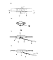
本発明の蒸着ボートのうち、線状溝部を1つ設け、温度センサーとしてシース熱電対を設けた場合について図1を用いて示す。図1(a)は、本発明の蒸着ボートの上面から見た模式図である。図1(b)は図1(a)のX―X線断面の模式図である。図1(c)は底面から見たの模式図である。図1(d)は(a)のY―Y線断面の模式図である。 In the vapor deposition boat of the present invention, a case where one linear groove portion is provided and a sheath thermocouple is provided as a temperature sensor will be described with reference to FIG. Fig.1 (a) is the schematic diagram seen from the upper surface of the vapor deposition boat of this invention. FIG.1 (b) is a schematic diagram of the XX cross section of Fig.1 (a). FIG.1 (c) is the schematic diagram seen from the bottom face. FIG. 1D is a schematic diagram of a cross section taken along line YY in FIG.
蒸着ボートは昇華性材料または有機材料を蒸着する際に用いられる蒸着材料を入れる容器部(1)を有する底板(2)と、少なくとも2穴またはメッシュ状の穴の開いた中板(3)または少なくとも1つ以上の穴の開いたカバー(4)のうちの少なくともどちらかまたは両方を重ね合わせたものである。 The vapor deposition boat has a bottom plate (2) having a container portion (1) for containing a vapor deposition material used for vaporizing a sublimable material or an organic material, and an intermediate plate (3) having at least two holes or mesh holes. It is a superposition of at least one or both of at least one or more perforated covers (4).
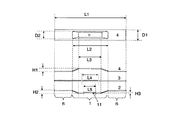
通常、該昇華性材料用蒸着ボートの大きさは図2において幅D1=8〜25mm、長さL1=80〜150mm程度である。底板、中板、カバーの板厚は0.05〜0.3mm程度である。底板の上に中板、カバーの順に重ねて通常は使用するが、粉や大きな粒子が舞い上がり難い材料やプレス成型した蒸着材料等を用いる場合は中板を省略して使用することもできる。 Usually, the size of the vapor deposition boat for sublimable materials is about width D1 = 8-25 mm and length L1 = 80-150 mm in FIG. The thickness of the bottom plate, the middle plate, and the cover is about 0.05 to 0.3 mm. Usually, the middle plate and the cover are stacked on the bottom plate in this order, and are normally used. However, when using a material in which powder or large particles do not rise easily, a press-deposited vapor deposition material, or the like, the middle plate can be omitted.
本発明の該蒸着ボート用基部の底に形成した線状溝部(11)は蒸着材料が入る容器部の容器の底の中心位置から容器の長辺方向に沿って20mm以内の場所を少なくとも一部に含み、かつ容器の内側に対し凸に深さ0.3mmから1.0mm、長さ5mmから30mm、幅0.3mmから3.0mmの線状溝部(11)を有する必要がある。 The linear groove portion (11) formed on the bottom of the base for the vapor deposition boat of the present invention has at least a part within 20 mm along the long side direction of the container from the center position of the container bottom of the container portion into which the vapor deposition material enters. And a linear groove (11) having a depth of 0.3 mm to 1.0 mm, a length of 5 mm to 30 mm, and a width of 0.3 mm to 3.0 mm, which is convex to the inside of the container.
線状溝部の位置が容器の底の中心位置から容器の長辺方向に沿って20mm以内の場所を少なくとも一部に含むことが必要である。もし、線状溝部がこれらの範囲を含まない場合、測定温度が蒸着材料の温度を正確に反映しない可能性がある。また、線状溝部の長さは5mmより短い場合はシース熱電対が抜けやすく、30mmより長い場合はシース熱電対を差し込む毎に熱電対の先端位置が一定せず測定温度の再現性が低下する。さらに好ましくは10mmから20mmの長さが望ましい。 It is necessary that the position of the linear groove part includes at least a portion within 20 mm from the center position of the bottom of the container along the long side direction of the container. If the linear groove does not include these ranges, the measured temperature may not accurately reflect the temperature of the vapor deposition material. In addition, when the length of the linear groove is shorter than 5 mm, the sheath thermocouple can be easily removed. When the length of the linear groove is longer than 30 mm, the tip position of the thermocouple is not constant every time the sheath thermocouple is inserted, and the reproducibility of the measurement temperature is lowered. . More preferably, a length of 10 mm to 20 mm is desirable.
また、線状溝部の深さは0.3mmより浅いと熱電対が差し込めず、1.0mmより深いとプレス時に底板にヒビが入る場合がある。好ましい深さは熱電対の直径と同程度から2〜3倍である。また、線状溝部の幅は0.3mmより狭いとシース熱電対が差し込めず、3.0mmより広いとシース熱電対が抜けやすくなる。好ましい幅はシース熱電対を容易に差し込める幅であり、シース熱電対の直径よりもやや広めから2〜3倍である。 Further, if the depth of the linear groove is less than 0.3 mm, the thermocouple cannot be inserted, and if it is deeper than 1.0 mm, the bottom plate may be cracked during pressing. The preferred depth is about the same as the diameter of the thermocouple to 2-3 times. Further, when the width of the linear groove is smaller than 0.3 mm, the sheath thermocouple cannot be inserted, and when it is larger than 3.0 mm, the sheath thermocouple is easily removed. The preferred width is a width that allows the sheath thermocouple to be easily inserted, and is a little wider than the diameter of the sheath thermocouple and is 2 to 3 times.
以上より、本発明の該蒸着ボート用基部の底に形成した線状溝部(11)にシース熱電対(9)を差し込むことができ、蒸着ボート中心付近の温度を再現性良く安定して測ることができる。 As described above, the sheath thermocouple (9) can be inserted into the linear groove (11) formed at the bottom of the base for the vapor deposition boat of the present invention, and the temperature near the center of the vapor deposition boat can be measured stably with good reproducibility. Can do.
シース熱電対(9)差し込み用線状溝部(11)を有する該蒸着ボートの電極板部と容器部を含む底板(2)はタンタル、モリブデン、ニオブ、ニッケルの中から選ばれた純度99質量%以上の金属板をプレス加工して溶接加工せずに一体で作られる。純度99質量%以上、好ましくは99.9質量%以上の高純度の高融点金属は真空中の加熱によるガス放出や素材成分の蒸発が少ない。通常の蒸着ボートに用いられているタンタル、モリブデン、ニオブの高融点金属を用いた場合にはボート自体は1000℃以上の高温まで使用することができる。 The bottom plate (2) including the electrode plate portion and the vessel portion of the vapor deposition boat having the linear groove portion (11) for inserting the sheath thermocouple (9) has a purity of 99% by mass selected from tantalum, molybdenum, niobium and nickel The above-mentioned metal plate is integrally formed without pressing and welding. A high-purity refractory metal having a purity of 99% by mass or more, preferably 99.9% by mass or less, emits less gas and evaporates material components by heating in vacuum. In the case of using a refractory metal such as tantalum, molybdenum, or niobium used in ordinary vapor deposition boats, the boat itself can be used up to a high temperature of 1000 ° C. or higher.
ニッケル板を用いる場合には好ましくは含有炭素量0.02質量%以下のニッケルを用いると300℃以上の温度でも炭素による脆化がなく有機物蒸着時の150℃から600℃の温度範囲で問題なく蒸着ボートとして使用できる。ニッケルを使用すると、高融点金属を使う場合よりもプレス加工しやすく、材料費も低コストになる。 In the case of using a nickel plate, it is preferable that nickel having a carbon content of 0.02% by mass or less is used, and there is no embrittlement due to carbon even at a temperature of 300 ° C. or higher, and there is no problem in a temperature range from 150 ° C. to 600 ° C. Can be used as a vapor deposition boat. When nickel is used, it is easier to press than using a refractory metal, and the material cost is also low.
また、底板は1枚の薄板からプレス加工で作られることにより、電気溶接の場合に溶接痕が付き表面が凸凹になり、凸凹部に蒸着材料が焼き付いたりすることがなく洗浄も容易で生産性が高い。また、折り紙のような折込み加工でなく、プレス加工で電極板部、容器部を一体で作るため金属板を薄く成形でき、抵抗加熱電流を少なくでき小さい蒸着電源の使用ですむ利点がある。プレスの際はひび割れを防ぐためにフッ素系等の潤滑油または潤滑樹脂を使っても良い。 In addition, the bottom plate is made from a single thin plate by pressing, so that in the case of electric welding, the surface becomes uneven and the surface becomes uneven, and the deposition material does not burn into the uneven portion, making it easy to clean and productive. Is expensive. In addition, since the electrode plate part and the container part are integrally formed by pressing rather than folding like origami, the metal plate can be formed thin, and there is an advantage that a resistance heating current can be reduced and a small evaporation power source can be used. In pressing, a fluorine-based lubricating oil or a lubricating resin may be used to prevent cracking.
また、底板はランクフォード値(薄板の引っ張り試験において、板幅方向の対数歪み/板厚方向の対数歪み 以下r値と略す)が2以上、好ましくは2.5以上のステンレス板をプレス加工して一体で作られる。 The bottom plate is a stainless plate having a Rankford value (logarithmic strain in the plate width direction / logarithmic strain in the plate thickness direction, hereinafter abbreviated as r value) of 2 or more, preferably 2.5 or more. And made in one piece.
フェライト系ステンレス鋼(クロム系ステンレス鋼)のランクフォード値を大きくするためには含有炭素濃度を0.01質量%以下、好ましくは0.001質量%以下にすることおよび熱間圧延工程での微小フェライト粒径化加工が重要である。ステンレスは純金属ではないが、マンガン等の蒸気圧の高い成分をほとんど含まず、且つ、炭素含有量の少ないプレス加工性の良いステンレスを用いた場合、有機物の蒸着温度範囲である150℃から600℃では放出ガスは少なく問題なく使用でき、高融点純金属材料やニッケルを用いた場合に比べさらに低コスト化できる利点がある。底板にステンレス鋼を用いた場合もプレスの際はひび割れを防ぐためにフッ素系等の潤滑油または潤滑樹脂を使っても良い。 In order to increase the Rankford value of ferritic stainless steel (chromium stainless steel), the concentration of contained carbon should be 0.01% by mass or less, preferably 0.001% by mass or less, and minute in the hot rolling process. Ferrite grain size processing is important. Although stainless steel is not a pure metal, it contains almost no high vapor pressure components such as manganese and has a low carbon content and good press workability. At 0 ° C., the emitted gas is small and can be used without any problem, and there is an advantage that the cost can be further reduced as compared with the case of using a high melting point pure metal material or nickel. Even when stainless steel is used for the bottom plate, fluorine-based lubricating oil or lubricating resin may be used during pressing in order to prevent cracking.
カバー(4)、中板(3)に用いられる材質は、底板(2)の材質と同じにした方が熱膨張による反り等の変形が小さくより望ましいが、熱膨張の近い材料ならば別々でも良い。また、カバー(4)、中板(3)における穴はプレス時に同時に形成するか、後で所望の直径と数にパンチで抜き打ち加工するか、ドリルで穴加工を行っても良い。 The material used for the cover (4) and the middle plate (3) is preferably the same as the material of the bottom plate (2), so that deformation such as warpage due to thermal expansion is less desirable. good. Further, the holes in the cover (4) and the intermediate plate (3) may be formed at the same time as pressing, or may be punched to a desired diameter and number later, or may be drilled.
本発明の蒸着ボートにおいて容器部の底部の外側に温度センサーを接触保持させる保持機構としては、底部に容器内側に向かって線状溝部を設け溝部に温度センサーを固定する方法以外に、容器外側に向かって線状凸部を2つ以上設けその2つの線状凸部の間の溝部に温度センサーを固定する方法、また、金属バンドを用いて温度センサーを固定する方法が挙げられるがこの限りではない。金属バンドは温度センサーを固定するための線状溝部または線状凸部を1つ以上有していてもかまわない。また、これらの方法を組み合わせることによって温度センサーを固定することも可能である。 In the vapor deposition boat of the present invention, as a holding mechanism for holding the temperature sensor in contact with the outside of the bottom of the container part, a linear groove part is provided on the bottom part toward the inside of the container, and the temperature sensor is fixed to the groove part. There are a method of fixing two or more linear protrusions toward the groove between the two linear protrusions, and a method of fixing the temperature sensor using a metal band. Absent. The metal band may have one or more linear grooves or linear protrusions for fixing the temperature sensor. It is also possible to fix the temperature sensor by combining these methods.
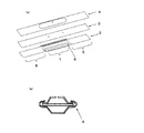
次に本発明蒸着ボートのうち、蒸着ボート底部に線状溝部を設け、金属バンドをあわせて用い、温度センサーとしてシース熱電対を使用した場合について図3、図4を用いて示す。 Next, in the vapor deposition boat of the present invention, a case where a linear groove portion is provided at the bottom of the vapor deposition boat, a metal band is used together, and a sheath thermocouple is used as a temperature sensor will be described with reference to FIGS.
図4(a)は線状溝部(11)に差し込んだ直径0.1mmから0.7mmのシース熱電対(9)を固定可能な図3に示す幅Wが5mmから25mmで板厚が0.03mmから0.3mmの金属板で作った固定用金属バンド(12)を昇華性材料用蒸着ボートの容器部に巻き込み、バンド両端を内側に少し折り曲げたツメ部(13)をガイド部(8)に引っ掛けはめ込み、差し込んだシース熱電対(9)を固定できるようにした蒸着ボートである。図4(b)はシース熱電対(9)を固定した状態でのY−Y断面の模式図、図4(c)はそのX−X断面の模式図、図4(d)は側面からの模式図である。 FIG. 4 (a) shows that a sheath thermocouple (9) having a diameter of 0.1 mm to 0.7 mm inserted into the linear groove (11) can be fixed. The width W shown in FIG. A fixing metal band (12) made of a metal plate of 03 mm to 0.3 mm is wound around the container part of the vapor deposition boat for sublimable materials, and a claw part (13) in which both ends of the band are bent slightly inside is a guide part (8). This is a vapor deposition boat that can be hooked on and fixed to the inserted sheathed thermocouple (9). 4 (b) is a schematic view of the YY cross section with the sheath thermocouple (9) fixed, FIG. 4 (c) is a schematic view of the XX cross section, and FIG. 4 (d) is a side view. It is a schematic diagram.
シース熱電対を外す場合には固定用金属バンド(12)をスライドさせるかツメ部(13)を引っ張ることにより、容易に脱着することができる。 When the sheath thermocouple is removed, it can be easily detached by sliding the fixing metal band (12) or pulling the claw portion (13).
板厚は0.03mmより薄いと熱電対を固定するための強度が足りず、固定用金属バンドの幅Wは5mmより短いとシース熱電対がふらつき外れ易く、板厚が0.3mmより厚く幅Wが25mmより長いと、金属バンドの板厚分だけ蒸着ボートの電気抵抗が下がるため、加熱により多くの電流が必要となる。 If the plate thickness is less than 0.03 mm, the strength for fixing the thermocouple is insufficient, and if the width W of the metal band for fixing is less than 5 mm, the sheath thermocouple is likely to come off and the plate thickness is thicker than 0.3 mm. If W is longer than 25 mm, the electric resistance of the vapor deposition boat is lowered by the thickness of the metal band, so that more current is required for heating.
しかし、固定用金属バンドを蒸着ボートの中央付近に装着することによりボート中央部の電気抵抗値を下げ中央部での発熱量を下げ、温度が高くなり易い中央部の温度を下げて、容器部の温度をより均一化する効果がある。より好ましくは固定用金属バンドの幅Wが10mm〜20mm程度、板厚0.05mm〜0.1mm程度である。固定用金属バンドの材質は600℃以下の温度で使う場合、少なくとも600℃で十分な強度を持ち融着せずガス放出が少ない金属であれば良い。より好ましくはタンタル、モリブデン、ニオブ、ニッケルの金属板またはステンレスの中から選ばれ使うことができる。好ましくは底板と同じ材質が良い。 However, by attaching a metal band for fixing near the center of the vapor deposition boat, the electrical resistance value at the center of the boat is lowered, the amount of heat generated at the center is lowered, the temperature at the center where the temperature tends to rise is lowered, and the container part This has the effect of more uniformizing the temperature. More preferably, the width W of the fixing metal band is about 10 mm to 20 mm and the plate thickness is about 0.05 mm to 0.1 mm. When the metal band for fixing is used at a temperature of 600 ° C. or lower, it may be a metal that has sufficient strength at least at 600 ° C. and does not melt and emits less gas. More preferably, a metal plate of tantalum, molybdenum, niobium, nickel, or stainless steel can be selected and used. The same material as the bottom plate is preferable.
また、シース熱電対はシース長10cm以上2m以下で、少なくとも先端から1cm、好ましくは10cmの感熱部を除き内部ジグと接触する恐れのある部分を絶縁保護した直径0.3mmから0.7mm、さらに好ましくは直径0.3mmから0.5mmのシース熱電対を蒸着装置の真空槽への導入用スリーブまたはフランジに1本以上通したものである。図8に1例としてスリーブに2本の熱電対を通し固定したものを示す。 The sheath thermocouple has a sheath length of 10 cm or more and 2 m or less, and has a diameter of 0.3 mm to 0.7 mm in which a portion that may come into contact with the internal jig except at least 1 cm from the tip, preferably 10 cm, may be in contact with the internal jig. Preferably, one or more sheath thermocouples having a diameter of 0.3 mm to 0.5 mm are passed through a sleeve or flange for introduction into the vacuum chamber of the vapor deposition apparatus. FIG. 8 shows an example in which two thermocouples are fixed to the sleeve through the sleeve.
本シース熱電対は柔軟に曲げてボート底部の線状溝部に差し込むために、直径は0.7mm以下が望ましい。0.3mm以下の場合は曲げにより切れやすくなる。さらに好ましくは0.3mmから0.5mmのシース熱電対を用いる。長さは10cmより短い場合はボートの底に差し込むために十分な長さではなく、2mより長い場合は小さい径に巻いて収容しても小型蒸着装置内での収容場所に問題が生じる。さらに好ましい長さは20cmから40cmであり、蒸着ボートと同程度の高さの導入ポートからスリーブ(14)またはフランジ付き熱電対を導入するのが望ましい。 In order to bend the sheath thermocouple flexibly and insert it into the linear groove at the bottom of the boat, the diameter is preferably 0.7 mm or less. In the case of 0.3 mm or less, it becomes easy to cut by bending. More preferably, a sheath thermocouple of 0.3 mm to 0.5 mm is used. When the length is shorter than 10 cm, the length is not sufficient to be inserted into the bottom of the boat. When the length is longer than 2 m, a problem arises in the accommodation place in the small vapor deposition apparatus even if it is wound around a small diameter. A more preferred length is 20 cm to 40 cm, and it is desirable to introduce a sleeve (14) or a flanged thermocouple from an introduction port as high as the vapor deposition boat.
シース熱電対は蒸着装置真空槽内のアース電位となっている内部ジグと接触し、シース熱電対を通して電流が流れジュール熱によりシース熱電対が加熱される場合がある。本発明のシース熱電対は、その問題を防ぐために先端部以外をポリイミドチューブを被せ被覆するか、またはポリイミド等の耐熱絶縁樹脂を塗布し絶縁膜被覆部(15)を形成したものである。その際、シース熱電対先端から少なくとも1cmまでの感熱部、さらに好ましくは10cmのところまでの部分は、耐熱温度以上に加熱され分解する恐れがあるために絶縁膜非被覆部(16)を設ける。 In some cases, the sheath thermocouple contacts an internal jig having a ground potential in the vacuum chamber of the vapor deposition apparatus, current flows through the sheath thermocouple, and the sheath thermocouple is heated by Joule heat. In order to prevent the problem, the sheath thermocouple of the present invention is formed by covering a portion other than the tip portion with a polyimide tube or applying a heat-resistant insulating resin such as polyimide to form an insulating film covering portion (15). At that time, the heat sensitive part from the tip of the sheath thermocouple to at least 1 cm, more preferably the part up to 10 cm, is heated to a temperature higher than the heat resistant temperature and may be decomposed, so an insulating film non-covering part (16) is provided.
シース熱電対(9)を真空蒸着装置の導入ポートより導入し、本発明の蒸着ボートに固定することにより、真空蒸着中の蒸着ボートの温度に対応した熱電対の出力を正確に再現性良く測定し、該出力電圧をディジタル指示調節計またはプログラム調節計等の蒸着電源制御装置の入力端子に入力し、所望の設定温度に対応する制御信号電流または電圧をスイッチング方式直流電源またはサイリスタ方式交流電源等の蒸着ボート加熱用電源に出力し、電源の直流または交流における電流値、電圧、周波数、出力波形等のいずれかを制御し、昇華性材料用蒸着ボートに流れる電流を実効電流200A以下において±0.1A以下の精度かつ0.1秒以下の制御周期で制御することで蒸着ボートの温度を150℃から600℃の温度範囲において±1℃以下の精度で制御できる。 The sheath thermocouple (9) is introduced from the introduction port of the vacuum vapor deposition device and fixed to the vapor deposition boat of the present invention, so that the thermocouple output corresponding to the temperature of the vapor deposition boat during vacuum vapor deposition is accurately measured with good reproducibility. The output voltage is input to an input terminal of a vapor deposition power supply controller such as a digital indicating controller or a program controller, and a control signal current or voltage corresponding to a desired set temperature is input to a switching DC power supply or a thyristor AC power supply. Is output to the power source for heating the vapor deposition boat, and the current value, voltage, frequency, output waveform or the like of the direct current or the alternating current of the power source is controlled, and the current flowing through the vapor deposition boat for sublimable material is ± 0 at an effective current of 200 A or less. . ± 1 ° C within the temperature range from 150 ° C to 600 ° C by controlling the accuracy of 1A or less with a control cycle of 0.1 second or less It can be controlled with the following accuracy.
以下本発明の実施例について述べる。
〔蒸着ボート作製実施例1〕
純度99.9%以上のモリブデン板を金型を使ってプレス打ち抜き加工をで、0.1mm厚のカバー(4)および底板(2)、0.05mm厚の中板(3)、を作製し本発明の昇華性材料用蒸着ボートを作製した。蒸着ボートの寸法を図2で示した寸法記号を用いて示す。L1=100mm、L2=40mm、L3=30mm、L4=20mm、L5=13mm、D1=12mm、H1=3mm、H2=3mm、H3=1mmである。
Examples of the present invention will be described below.
[Vapor deposition boat production example 1]
Press punching of a 99.9% or higher molybdenum plate using a die to produce a cover (4) with a thickness of 0.1 mm, a bottom plate (2), and a middle plate (3) with a thickness of 0.05 mm. A vapor deposition boat for a sublimable material of the present invention was produced. The dimension of a vapor deposition boat is shown using the dimension symbol shown in FIG. L1 = 100 mm, L2 = 40 mm, L3 = 30 mm, L4 = 20 mm, L5 = 13 mm, D1 = 12 mm, H1 = 3 mm, H2 = 3 mm, H3 = 1 mm.
熱電対固定用金属バンド(12)は熱膨張を合わせるために蒸着ボートの底板(2)と同じ材質であるモリブデンで板厚0.05mm、幅W=10mmで作製した。
固定用金属バンド付昇華性材料用蒸着ボートに熱電対作製例で作製した熱電対を差し込み固定し蒸着物を入れずにターボポンプ(排気速度300L/s)付蒸着装置(真空チャンバー直径30cm、高さ60cm)にセットし0.0004Pa下で通電し、室温から600℃まで通電加熱を行った。真空度は電離真空計でモニターした。蒸着ボートからの放出ガスによる急激な真空度の悪化は無く0.001Pa以下の圧力が維持された。蒸着ボートの熱による実用上の強度低下はなかった。
The thermocouple-fixing metal band (12) was made of molybdenum, which is the same material as the bottom plate (2) of the vapor deposition boat, with a plate thickness of 0.05 mm and a width W = 10 mm in order to match thermal expansion.
Vapor deposition equipment (vacuum chamber diameter: 30 cm, high) with a turbo pump (pumping speed: 300 L / s) without inserting the vapor deposition material into the vapor deposition boat for sublimation materials with a metal band for fixation. And was energized under 0.0004 Pa, and energized and heated from room temperature to 600 ° C. The degree of vacuum was monitored with an ionization vacuum gauge. There was no sudden deterioration of the degree of vacuum due to the gas released from the vapor deposition boat, and a pressure of 0.001 Pa or less was maintained. There was no practical decrease in strength due to the heat of the evaporation boat.
〔蒸着ボート作製実施例2〜4〕
モリブデン板に代えてタンタル(作製実施例2)、タングステン(作製実施例3)、ニオブ(作製実施例4)の純度99.9%以上の各材料を用いた場合にも蒸着ボート作製実施例1と同様に作製できた。真空蒸着装置中で各蒸着ボートの通電加熱を行ったところ、600℃以下での蒸着ボートからの放出ガスによる急激な真空度の悪化は無く0.001Pa以下の圧力が維持された。蒸着ボートの熱による実用上の強度低下はなかった。
[Vapor deposition boat production examples 2 to 4]
Vapor deposition boat manufacturing example 1 also when each material of purity 99.9% or more of tantalum (manufacturing example 2), tungsten (manufacturing example 3), niobium (manufacturing example 4) is used instead of the molybdenum plate. It was possible to produce similarly. When energization heating of each vapor deposition boat was performed in a vacuum vapor deposition apparatus, there was no sudden deterioration of the degree of vacuum due to the gas released from the vapor deposition boat at 600 ° C. or lower, and a pressure of 0.001 Pa or lower was maintained. There was no practical decrease in strength due to the heat of the evaporation boat.
〔蒸着ボート作製実施例5〜6〕
ニッケル270(純度99.9質量%以上)板(作製実施例5)およびニッケル201板(純度99.6質量%、炭素濃度0.02質量%以下)(作製実施例6)を用いた場合にも蒸着ボート作製実施例1と同様に作製できた。真空蒸着装置中で各蒸着ボートの通電加熱を行ったところ、600℃以下での蒸着ボートからの放出ガスによる急激な真空度の悪化は無く0.001Pa以下の圧力が維持された。蒸着ボートの熱による実用上の強度低下はなかった。
[Vapor deposition boat production examples 5 to 6]
When using a nickel 270 (purity 99.9% by mass or more) plate (production example 5) and a nickel 201 plate (purity 99.6% by mass, carbon concentration 0.02% by mass or less) (production example 6) Was also produced in the same manner as in the vapor deposition boat production example 1. When energization heating of each vapor deposition boat was performed in a vacuum vapor deposition apparatus, there was no sudden deterioration of the degree of vacuum due to the gas released from the vapor deposition boat at 600 ° C. or lower, and a pressure of 0.001 Pa or lower was maintained. There was no practical decrease in strength due to the heat of the evaporation boat.
〔蒸着ボート作製比較例1〕
ニッケル200板(純度99.6質量%、炭素濃度0.15質量%)を用い蒸着ボート作製例1と同様に作製した。真空蒸着装置中で各蒸着ボートの通電加熱を行ったところ、600℃以下での蒸着ボートからの放出ガスによる急激な真空度の悪化は無く0.001Pa以下の圧力が維持されたが、熱劣化で金属がもろくなり折れやすくなった。
[Vapor deposition boat production comparative example 1]
A nickel 200 plate (purity 99.6 mass%, carbon concentration 0.15 mass%) was used in the same manner as in the vapor deposition boat production example 1. When energization heating of each vapor deposition boat was performed in a vacuum vapor deposition system, the pressure of 0.001 Pa or less was maintained while there was no sudden deterioration in the degree of vacuum due to the gas released from the vapor deposition boat at 600 ° C. or lower. The metal became fragile and easily broken.
〔蒸着ボート作製実施例7〕
炭素濃度0.001質量%以下、r=2.6のクロム系ステンレス鋼(川崎製鉄製RSX−1の完全連続熱間圧延板)を用いて蒸着ボート作製例1と同様に蒸着ボートを作製した。真空蒸着装置中で各蒸着ボートの通電加熱を行ったところ、600℃以下での蒸着ボートからの放出ガスによる急激な真空度の悪化は無く0.001Pa以下の圧力が維持された。蒸着ボートの熱による実用上の強度低下はなかった。また、底板の線状溝部を幅0.5mm、深さ1mm程度の深絞りプレス加工をしてもヒビ割れが生じなかった。
[Vapor deposition boat manufacturing example 7]
A vapor deposition boat was produced in the same manner as in vapor deposition boat production example 1 using a chromium-based stainless steel (RSX-1 made by Kawasaki Steel, RSX-1) having a carbon concentration of 0.001% by mass or less and r = 2.6. . When energization heating of each vapor deposition boat was performed in a vacuum vapor deposition apparatus, there was no sudden deterioration of the degree of vacuum due to the gas released from the vapor deposition boat at 600 ° C. or lower, and a pressure of 0.001 Pa or lower was maintained. There was no practical decrease in strength due to the heat of the evaporation boat. Further, even if the linear groove portion of the bottom plate was subjected to deep drawing press processing having a width of about 0.5 mm and a depth of about 1 mm, no cracks were generated.
〔蒸着ボート作製比較例2〕
r値が1.0のステンレス304を用い蒸着ボート作製例7と同様に作成した場合には、線状溝部を幅0.5mmで深さ1mmにプレスした場合にヒビが入る場合があった。
[Evaporation boat production comparative example 2]
When stainless steel 304 having an r value of 1.0 was used in the same manner as in vapor deposition boat production example 7, cracks sometimes occurred when the linear groove was pressed to a width of 0.5 mm and a depth of 1 mm.
〔熱電対作製実施例〕
シース熱電対は、導入ポート(真空ゲージポートと共通)へ差し込むためのO−リングシール付きステンレス製スリーブに材質NCF600(インコネル)製シース付きK熱電対(直径0.5mm、シース長40cm)を2本通しエポキシ接着剤で開口を密封固定し使用した。スリーブとシース熱電対先端から10cmまでの間を古河電工性ポリイミドチューブ(耐熱温度400℃)で絶縁保護した。
[Examples of thermocouple production]
The sheath thermocouple is a stainless steel sleeve with an O-ring seal that is inserted into the introduction port (common with the vacuum gauge port) and a K thermocouple with a material NCF600 (Inconel) sheath (diameter 0.5 mm, sheath length 40 cm). The opening was hermetically fixed with a permanent epoxy adhesive and used. Insulation protection was performed between the sleeve and the sheath thermocouple from the tip to 10 cm with a Furukawa Electric polyimide tube (heat-resistant temperature 400 ° C.).
〔蒸着実施例1〕
Ni270製の本発明の線状溝部付き蒸着ボートをプレス加工により作製した。ボートの寸法はL1=100mm、L2=40mm、L3=30mm、L4=20mm、L5=13mm、D1=18mm、H1=5mm、H2=5mm、H3=1mmであった。蒸着ボートの底板に蒸着材料として(化1)に示すAlq3化合物をハンドプレスで圧縮し100mg入れた後、中板とカバーを被せ、ガイド部をかしめて底板に中板とカバーを密着させた。その後固定用金属バンドを底板の中央付近に取り付け、線状溝部に本発明のシース熱電対の1本を差し込み固定した。
[Vapor deposition example 1]
A vapor deposition boat with linear grooves of the present invention made of Ni270 was produced by pressing. The boat dimensions were L1 = 100 mm, L2 = 40 mm, L3 = 30 mm, L4 = 20 mm, L5 = 13 mm, D1 = 18 mm, H1 = 5 mm, H2 = 5 mm and H3 = 1 mm. After compressing 100 mg of Alq 3 compound shown in (Chemical Formula 1) as a vapor deposition material on the bottom plate of the vapor deposition boat with a hand press, the intermediate plate and the cover were covered, and the guide portion was crimped to adhere the intermediate plate and the cover to the bottom plate. . Thereafter, a fixing metal band was attached near the center of the bottom plate, and one of the sheathed thermocouples of the present invention was inserted and fixed in the linear groove.
熱電対の補償導線は横河電機製ディジタル指示調節計に接続され、ディジタル指示調節計からの4−20mA出力信号はシマデン製サイリスタ電力調整器に入力され蒸着ボートに印加される電流を調整した。蒸着装置の電極ジグに蒸着ボートを固定後、0.001Pa以下まで三菱重工製ターボポンプで減圧した。電流を73.0Aまで徐々に上げ±0.1A以下の精度、かつ0.1秒以下の制御周期で制御し250.0℃±0.1℃の精度で加熱を行った。 The compensation wire of the thermocouple was connected to a Yokogawa digital indicating controller, and a 4-20 mA output signal from the digital indicating controller was input to a Shimaden thyristor power adjuster to adjust the current applied to the evaporation boat. After fixing the vapor deposition boat to the electrode jig of the vapor deposition apparatus, the pressure was reduced with a turbo pump manufactured by Mitsubishi Heavy Industries to 0.001 Pa or less. The current was gradually raised to 73.0 A, and heating was performed with an accuracy of ± 0.1 A or less and a control cycle of 0.1 seconds or less and an accuracy of 250.0 ° C. ± 0.1 ° C.
蒸着材料は蒸着ボート上から30cm離したガラス基板上に約0.1±0.001nm/sの蒸着速度で安定に蒸着した。蒸着速度は水晶振動子式膜厚計でモニターでした。その後、一定温度で50nmの膜厚まで蒸着を行った。蒸着ボート内の蒸着材料は容器部内で中央部からだけでなくほぼ均一に昇華し減っていた。蒸着膜中に分解や噴出による粒子の付着はなかった。 The deposition material was stably deposited at a deposition rate of about 0.1 ± 0.001 nm / s on a glass substrate 30 cm away from the deposition boat. The deposition rate was monitored with a quartz crystal film thickness meter. Thereafter, vapor deposition was performed at a constant temperature to a film thickness of 50 nm. The vapor deposition material in the vapor deposition boat sublimated almost uniformly in the container part as well as from the central part. There was no adhesion of particles due to decomposition or eruption in the deposited film.
〔蒸着実施例2〕
RSX−1製の本発明の線状溝部付き蒸着ボートをプレス加工により作製した。ボートの寸法はL1=100mm、L2=40mm、L3=30mm、L4=20mm、L5=13mm、D1=18mm、H1=5mm、H2=5mm、H3=1mmであった。(化2)に示すDMQdを蒸着材料とし100mg入れた後、蒸着実施例1のAlq3の入ったボートと並べてセットし、185℃±0.1℃で0.0005±0.00003nm/sの蒸着速度でAlq3と共蒸着を行った。50nm厚のDMQdドープAlq3蒸着膜を成膜した。膜中に分解や噴出による粒子の付着はなく、膜厚方向でドープ濃度が0.5%(膜厚比)で一定の蒸着膜ができた。蒸着ボート内の蒸着材料は容器部内で中央部からだけでなくほぼ均一に昇華し減っていた。
[Deposition Example 2]
A vapor deposition boat with linear grooves of the present invention made of RSX-1 was produced by pressing. The boat dimensions were L1 = 100 mm, L2 = 40 mm, L3 = 30 mm, L4 = 20 mm, L5 = 13 mm, D1 = 18 mm, H1 = 5 mm, H2 = 5 mm and H3 = 1 mm. After adding 100 mg of DMQd shown in (Chemical Formula 2) as a vapor deposition material, it was set side by side with the boat containing Alq 3 of vapor deposition example 1, and 0.0005 ± 0.00003 nm / s at 185 ° C. ± 0.1 ° C. Co-deposition with Alq 3 was performed at a deposition rate. A 50 nm thick DMQd-doped Alq 3 vapor deposition film was formed. There was no adhesion of particles due to decomposition or ejection in the film, and a constant vapor deposition film was formed at a dope concentration of 0.5% (film thickness ratio) in the film thickness direction. The vapor deposition material in the vapor deposition boat sublimated almost uniformly in the container part as well as from the central part.
〔蒸着実施例3〕
Mo製の本発明の線状溝部付き蒸着ボートをプレス加工により作製した。ボートの寸法はL1=100mm、L2=40mm、L3=30mm、L4=20mm、L5=13mm、D1=12mm、H1=3mm、H2=3mm、H3=1mmであった。銅フタロシアニンを蒸着材料とし40mg入れ、61.0A、470℃±1℃で0.050±0.005nm/sの蒸着速度で50nm厚の蒸着膜を作製できた。膜中に分解や噴出による粒子の付着はなかった。蒸着ボート内の蒸着材料は容器部内で中央部からだけでなくほぼ均一に昇華し減っていた。
[Deposition Example 3]
The vapor deposition boat with the linear groove part of this invention made from Mo was produced by press work. The dimensions of the boat were L1 = 100 mm, L2 = 40 mm, L3 = 30 mm, L4 = 20 mm, L5 = 13 mm, D1 = 12 mm, H1 = 3 mm, H2 = 3 mm, H3 = 1 mm. 40 mg of copper phthalocyanine was used as a deposition material, and a 50 nm thick deposited film was prepared at a deposition rate of 0.050 ± 0.005 nm / s at 61.0 A, 470 ° C. ± 1 ° C. There was no adhesion of particles due to decomposition or eruption in the film. The vapor deposition material in the vapor deposition boat sublimated almost uniformly in the container part as well as from the central part.
1・・・・容器部
2・・・・底板
3・・・・中板
4・・・・カバー
5・・・・蒸着材料
6・・・・電極板部
7・・・・電極ジグ
8・・・・ガイド部
9・・・・シース熱電対
10・・・・熱電対押し付け装置
11・・・・線状溝部
12・・・・固定用金属バンド
13・・・・ツメ部
14・・・・スリーブ
15・・・・絶縁膜被覆部
16・・・・絶縁膜非被覆部
17・・・・補償導線
18・・・・Oリング
DESCRIPTION OF
Claims (7)
It said temperature sensor is a sheathed thermocouple, a the sheath length 10cm or 2m or less, according to any one of claims 1 to 6 is insulated protect portions other than the heat-sensitive part which is in contact with the deposition boat by a heat-resistant resin Sheath thermocouple for vapor deposition boats.
Priority Applications (1)
| Application Number | Priority Date | Filing Date | Title |
|---|---|---|---|
| JP2005052660A JP4635643B2 (en) | 2005-02-28 | 2005-02-28 | Deposition boat and sheath thermocouple |
Applications Claiming Priority (1)
| Application Number | Priority Date | Filing Date | Title |
|---|---|---|---|
| JP2005052660A JP4635643B2 (en) | 2005-02-28 | 2005-02-28 | Deposition boat and sheath thermocouple |
Publications (2)
| Publication Number | Publication Date |
|---|---|
| JP2006233304A JP2006233304A (en) | 2006-09-07 |
| JP4635643B2 true JP4635643B2 (en) | 2011-02-23 |
Family
ID=37041284
Family Applications (1)
| Application Number | Title | Priority Date | Filing Date |
|---|---|---|---|
| JP2005052660A Expired - Fee Related JP4635643B2 (en) | 2005-02-28 | 2005-02-28 | Deposition boat and sheath thermocouple |
Country Status (1)
| Country | Link |
|---|---|
| JP (1) | JP4635643B2 (en) |
Families Citing this family (2)
| Publication number | Priority date | Publication date | Assignee | Title |
|---|---|---|---|---|
| JP6952972B2 (en) * | 2016-12-27 | 2021-10-27 | 助川電気工業株式会社 | Nickel sheath thermocouple |
| CN116140632A (en) * | 2023-02-21 | 2023-05-23 | 郑州大学 | Multi-layer boat and method for preparing refractory metal powder by using multi-layer boat |
Family Cites Families (4)
| Publication number | Priority date | Publication date | Assignee | Title |
|---|---|---|---|---|
| JPS58204173A (en) * | 1982-05-20 | 1983-11-28 | Toshiba Corp | Device and method for vapor deposition |
| JPS6254075A (en) * | 1985-09-02 | 1987-03-09 | Fujitsu Ltd | Vapor deposition boat |
| JPS6428366A (en) * | 1987-07-22 | 1989-01-30 | Shimadzu Corp | Crucible of vacuum deposition device |
| JP2002246175A (en) * | 2001-02-16 | 2002-08-30 | Sony Corp | Method and apparatus for forming organic material thin film, and method for manufacturing organic electroluminescent element |
-
2005
- 2005-02-28 JP JP2005052660A patent/JP4635643B2/en not_active Expired - Fee Related
Also Published As
| Publication number | Publication date |
|---|---|
| JP2006233304A (en) | 2006-09-07 |
Similar Documents
| Publication | Publication Date | Title |
|---|---|---|
| JP5284961B2 (en) | Pressure gauge for organic matter | |
| US7946762B2 (en) | Thermocouple | |
| US20060275933A1 (en) | Thermally conductive ceramic tipped contact thermocouple | |
| JP4879060B2 (en) | Substrate heating device | |
| JP2006153706A (en) | Thermometer and vapor phase growth apparatus | |
| JP2012080103A (en) | Susceptor and manufacturing method therefor | |
| CN112703268B (en) | Nitriding treatment device and nitriding treatment method | |
| KR20140004758A (en) | Methods and apparatus for a multi-zone pedestal heater | |
| WO1996035932A1 (en) | Temperature sensor element, temperature sensor having the same and method for producing the same temperature sensor element | |
| KR100445275B1 (en) | Tool tip and bonding tool comprising the tool tip and control method for the bonding tool | |
| TW201128739A (en) | Component package for maintaining safe operating temperature of components | |
| CN102221417A (en) | Contact temperature probe and method for manufacturing the same | |
| JP4635643B2 (en) | Deposition boat and sheath thermocouple | |
| JPH11312570A (en) | Ceramic heater | |
| US9846084B2 (en) | Vacuum heat treatment apparatus | |
| JP5320104B2 (en) | Ceramic heater and manufacturing method thereof | |
| US5944903A (en) | Effusion cell crucible with thermocouple | |
| US11862488B2 (en) | Substrate stage | |
| JP2008298617A (en) | Catalytic combustion type gas sensor and manufacturing method of catalytic combustion type gas sensor | |
| JPH07218348A (en) | Thin film thermocouple | |
| KR20140136142A (en) | self plasma chamber contaminating delay apparatus | |
| JP6319566B2 (en) | Metal nitride material for thermistor, manufacturing method thereof, and film type thermistor sensor | |
| JP4863176B2 (en) | Thin film heating element | |
| JP6319567B2 (en) | Metal nitride material for thermistor, manufacturing method thereof, and film type thermistor sensor | |
| JP7205079B2 (en) | temperature sensor |
Legal Events
| Date | Code | Title | Description |
|---|---|---|---|
| A621 | Written request for application examination |
Free format text: JAPANESE INTERMEDIATE CODE: A621 Effective date: 20080124 |
|
| A977 | Report on retrieval |
Free format text: JAPANESE INTERMEDIATE CODE: A971007 Effective date: 20100421 |
|
| A131 | Notification of reasons for refusal |
Free format text: JAPANESE INTERMEDIATE CODE: A131 Effective date: 20100427 |
|
| A521 | Request for written amendment filed |
Free format text: JAPANESE INTERMEDIATE CODE: A523 Effective date: 20100611 |
|
| TRDD | Decision of grant or rejection written | ||
| A01 | Written decision to grant a patent or to grant a registration (utility model) |
Free format text: JAPANESE INTERMEDIATE CODE: A01 Effective date: 20101026 |
|
| A01 | Written decision to grant a patent or to grant a registration (utility model) |
Free format text: JAPANESE INTERMEDIATE CODE: A01 |
|
| A61 | First payment of annual fees (during grant procedure) |
Free format text: JAPANESE INTERMEDIATE CODE: A61 Effective date: 20101108 |
|
| FPAY | Renewal fee payment (event date is renewal date of database) |
Free format text: PAYMENT UNTIL: 20131203 Year of fee payment: 3 |
|
| R150 | Certificate of patent or registration of utility model |
Ref document number: 4635643 Country of ref document: JP Free format text: JAPANESE INTERMEDIATE CODE: R150 Free format text: JAPANESE INTERMEDIATE CODE: R150 |
|
| LAPS | Cancellation because of no payment of annual fees |