JP4635569B2 - Roll mold manufacturing method and roll mold - Google Patents
Roll mold manufacturing method and roll mold Download PDFInfo
- Publication number
- JP4635569B2 JP4635569B2 JP2004321767A JP2004321767A JP4635569B2 JP 4635569 B2 JP4635569 B2 JP 4635569B2 JP 2004321767 A JP2004321767 A JP 2004321767A JP 2004321767 A JP2004321767 A JP 2004321767A JP 4635569 B2 JP4635569 B2 JP 4635569B2
- Authority
- JP
- Japan
- Prior art keywords
- master
- roll
- mold
- outer peripheral
- base material
- Prior art date
- Legal status (The legal status is an assumption and is not a legal conclusion. Google has not performed a legal analysis and makes no representation as to the accuracy of the status listed.)
- Expired - Fee Related
Links
Images


Description
本発明は、フィルムなどの表面加工に使用するロール金型の製造方法及びロール金型に関するものである。とくに、液晶表示装置のバックライトユニットに使用されるプリズムシート、プロジェクションテレビやマイクロフィルムリーダ等の投射スクリーンに使用されるフレネルレンズシート、レンチキュラレンズシート、光拡散シート等の光学シートの製造に使用されるロール金型の製造方法及びロール金型に関する。 The present invention relates to a method for manufacturing a roll mold used for surface processing of a film or the like and a roll mold . In particular, it is used to manufacture optical sheets such as prism sheets used in backlight units of liquid crystal display devices, Fresnel lens sheets used in projection screens such as projection televisions and microfilm readers, lenticular lens sheets, and light diffusion sheets. The present invention relates to a roll mold manufacturing method and a roll mold.
従来、円筒表面に凹凸を有するロール金型は、その凹凸形状を目的とする部材に押出成形などにより転写し機能を発現させるために使用されている。とくに液晶表示装置のバックライトユニットに使用されるプリズムシート、プロジェクションテレビやマイクロフィルムリーダ等の投射スクリーンに使用されるフレネルレンズシート、レンチキュラレンズシート、光拡散シート等の光学シートの用途では、その微細な凹凸形状に所定の光学性能が要求されるため、その製造に使用されるロール金型にもその円筒表面にサブミクロンオーダーの寸法精度で凹凸形状が形成されることが求められている。 2. Description of the Related Art Conventionally, roll dies having irregularities on a cylindrical surface have been used to develop functions by transferring the irregularities to members intended for the irregular shape by extrusion molding or the like. Especially in the use of prism sheets used in backlight units of liquid crystal display devices, optical sheets such as Fresnel lens sheets, lenticular lens sheets, and light diffusion sheets used in projection screens such as projection televisions and microfilm readers. Since a predetermined optical performance is required for such a concave and convex shape, it is required that the concave and convex shape is formed on the surface of the cylinder with a dimensional accuracy on the order of submicrons also in the roll mold used for the manufacture thereof.
このような用途で使用されるロール金型の製造方法として、表面に微細な凹凸形状が刻印された雄型を転写して該雄型に対応するフィルム状又は薄板状の雌型を作製し、該雌型をロール型母材の円筒表面に取り付けることによりロール金型を得る方法が提案されている(例えば、特許文献1参照。)。 As a method for producing a roll mold used in such applications, a male mold with a fine uneven shape engraved on its surface is transferred to produce a film-shaped or thin-plate female mold corresponding to the male mold, A method for obtaining a roll mold by attaching the female mold to the cylindrical surface of a roll mold base material has been proposed (see, for example, Patent Document 1).
しかしながら、フィルム状の雌型をロール型母材へ取り付けるにはハンドリングが困難であり、取り付けたとしても雌型に寄りやシワが入りやすく、目標の寸法精度でのロール金型の作製は難しかった。とくにロール金型が大きくなるほど、その作製が困難であった。
加えて、雌型取り付け時に凹凸に触れることがあり、凹凸面が汚れたり損傷を受けたりする問題があった。
However, it is difficult to handle the film-shaped female mold on the roll mold base material, and even if it is mounted, the female mold tends to slip and wrinkle, making it difficult to produce a roll mold with the target dimensional accuracy. . In particular, the larger the roll mold, the more difficult it was to produce.
In addition, there is a problem that the uneven surface may be touched when the female mold is attached, and the uneven surface becomes dirty or damaged.
また、上記方法では雄型をマスター原盤として雌型フィルムを繰り返し作製することが可能であるが、雌型は硬質であるために雄型のダメージが大きいために、1つの雄型で雌型を繰り返し作製できる回数は少なく限度があった。 In the above method, it is possible to repeatedly produce a female film using the male mold as a master master. However, since the female mold is hard and the male mold is damaged, the female mold is formed by one male mold. There were few limits to the number of times it could be produced repeatedly.
本発明は、以上の従来技術における問題に鑑みてなされたものであり、円筒表面の凹凸を寸法精度よく容易に作製することができる金型ロールの製造方法、及びその方法を用いた加工対象のシートに凹凸を寸法精度よく形成することができる金型ロールを提供することを目的とする。 The present invention has been made in view of the above-described problems in the prior art, and a method for manufacturing a mold roll capable of easily producing irregularities on a cylindrical surface with high dimensional accuracy, and a processing target using the method. It is an object of the present invention to provide a mold roll capable of forming irregularities on a sheet with high dimensional accuracy.
前記課題を解決するために提供する本発明は、外周表面に微細な凹凸を備えるロール金型の製造方法であって、可撓性を有し、一方の主面上に微細な凹凸が形成された平板形状の原盤の該凹凸形成面にめっき処理を施し、ついで前記原盤を、めっき面を内側に向けて撓ませながら円筒形状のロール型母材の外周面に巻き付けた後に、前記原盤をはずして前記凹凸が転写されためっき部分をロール型母材の外周面上に固定することを特徴とするロール金型の製造方法である(請求項1)。 The present invention provided to solve the above problems is a method of manufacturing a roll mold having fine irregularities on the outer peripheral surface, which is flexible and has fine irregularities formed on one main surface. The uneven surface of the flat plate-shaped master plate is plated, and then the master plate is wound around the outer peripheral surface of the cylindrical roll-shaped base material while bending the plated surface inward, and then the master plate is removed. Then, the plating part to which the unevenness is transferred is fixed on the outer peripheral surface of the roll mold base material (claim 1).
ここで、前記原盤は、基板の表面に微細な凹凸を形成した後、該基板の凹凸形状を可撓性を有するシートの表面に転写したものであることが好ましい。 Here, the master is preferably formed by forming fine irregularities on the surface of the substrate and then transferring the irregular shape of the substrate to the surface of the flexible sheet.
また、前記めっき処理として、最初に無電解めっき処理を施し、ついで電気めっき処理を施すとよい。 Further, as the plating treatment, electroless plating treatment may be performed first, followed by electroplating treatment.
前記課題を解決するために提供する本発明は、請求項1〜3のいずれか一に記載のロール金型の製造方法により製造され、円筒形状のロール型母材と、該ロール型母材の外周面に固定され外周表面に微細な凹凸を有する金属層とからなることを特徴とするロール金型である(請求項4)。 This invention provided in order to solve the said subject is manufactured by the manufacturing method of the roll metal mold | die as described in any one of Claims 1-3, A cylindrical roll type | mold base material, and this roll type | mold base material A roll mold characterized by comprising a metal layer fixed to the outer peripheral surface and having fine irregularities on the outer peripheral surface (Claim 4).
本発明のロール金型の製造方法によれば、原盤によりめっき部分が補強された状態でロール型母材の外周面への取り付け作業が行えるため、ハンドリングが容易であり、寄りやシワを発生させることなくめっき部分の取り付けが可能となる。また、めっき部分の凹凸転写面はロール型母材への該めっき部分の取り付けがおわるまでは原盤により保護されている状態であるため、取り付け作業時にめっき部分の凹凸を汚したり損傷させたりすることがない。また、基板からシートへの凹凸の転写は平面上で行われるために、寸法精度よく凹凸形状が写し取れるので、最終的にロール金型上に凹凸を目標通り形成することができる。さらに、可撓性を有するシートを使用することにより、所望の円筒形状に撓ませることができるのでロール型母材への取り付けが容易である。また、微細な凹凸を形成した基板を硬質のマスター原盤とし、該マスター原盤から比較的軟質のシートへの凹凸の転写が行われて原盤(マザー原盤)が作製されるようにすると、マスター原盤のダメージは少なく、1つのマスター原盤から多くのマザー原盤を繰り返し作製することが可能である。
本発明のロール金型によれば、寄りやシワなく金属層(めっき部分)がロール型母材外周面に固定され、かつ外周表面の凹凸に汚れや損傷がないので、本ロール金型を使用した加工によりシート上に凹凸を寸法精度よく形成することが可能となる。しかも、ロール金型の大型化が容易であり、大面積のシートを凹凸の寸法精度よく加工することが可能となる。
According to the method for manufacturing a roll mold of the present invention, since the work of attaching the roll mold base material to the outer peripheral surface can be performed in a state in which the plated portion is reinforced by the master, handling is easy, and deviation and wrinkles are generated. The plated portion can be attached without any problems. Also, since the uneven transfer surface of the plating part is protected by the master until the plating part is attached to the roll-type base material, the unevenness of the plating part may be soiled or damaged during the mounting operation. There is no. Further, since the unevenness is transferred from the substrate to the sheet on a flat surface, the uneven shape can be copied with high dimensional accuracy, so that the unevenness can be finally formed on the roll mold as desired. Furthermore, by using a flexible sheet, it can be bent into a desired cylindrical shape, so that it can be easily attached to a roll-type base material. In addition, if a substrate having fine irregularities is used as a hard master master and the irregularities are transferred from the master master to a relatively soft sheet to produce a master (mother master), the master master There is little damage, and many mother masters can be repeatedly produced from one master master.
According to the roll mold of the present invention, the metal layer (plated portion) is fixed to the outer peripheral surface of the roll mold base material without any deviation or wrinkle, and the irregularities on the outer peripheral surface are not soiled or damaged. As a result of the processing, irregularities can be formed on the sheet with high dimensional accuracy. In addition, it is easy to increase the size of the roll mold, and it becomes possible to process a large-area sheet with high dimensional accuracy .
以下、本発明に係るロール金型の製造方法について、その作製手順に従って説明する。
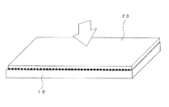
(S1)基板表面を加工して微細な凹凸を形成して、マスター原盤10とする(図1)。マスター原盤10の縦幅方向は最終的にロール金型の幅方向となり、横幅方向はロール金型の円周方向となる。
Hereinafter, the manufacturing method of the roll metal mold | die which concerns on this invention is demonstrated according to the preparation procedure.
(S1) The substrate surface is processed to form fine irregularities to form a master master 10 (FIG. 1). The longitudinal width direction of the
基板は、凹凸を形成する加工ができ、該凹凸部分が型としてある程度の強度をもつものであれば特に限定されない。例えば、アルミニウム、真鍮、ステンレス、銅、無酸素銅、ニッケル等の金属板;ポリメチルメタクリレート、ポリカーボネート、ポリエチレン、ポリプロピレン、エポキシ樹脂等の樹脂板などが挙げられる。 The substrate is not particularly limited as long as it can be processed to form unevenness, and the uneven portion has a certain degree of strength as a mold. Examples thereof include metal plates such as aluminum, brass, stainless steel, copper, oxygen-free copper, and nickel; resin plates such as polymethyl methacrylate, polycarbonate, polyethylene, polypropylene, and epoxy resin.
凹凸形状は、ロール金型の加工対象であるシートの用途、要求特性に応じて設定する。例えば、プリズムシートを作製するためのものであれば、マスター原盤10の横幅方向の断面形状を三角形状の溝あるいは突起が連続して配列されたもの(図1(b))とし、縦幅方向にこの断面形状の三角柱がマスター原盤10上に規則的に配置されたものとする(図1(a))。あるいは、マスター原盤10の横幅方向の断面形状を半球形状のピットとし、縦幅方向にこの断面形状の溝が原盤10上に規則的に配置されたものとしてもよい。また、光拡散シートを作製するためのものであれば、微細な凹凸がランダムに配列されたものとしてもよい。
The concavo-convex shape is set according to the use and required characteristics of the sheet to be processed by the roll mold. For example, if the prism sheet is to be manufactured, the cross-sectional shape of the
この凹凸を形成する加工方法は、上記凹凸形状に応じて適切な方法を選択すればよい。例えば、精密加工機を用いて基材表面を切削加工、あるいはUV、電子線又はレーザー光を用いたフォトリソグラフィの手法を用いて凹凸形状を作製する方法、サンドブラストにより研削剤を吹き付けて基板表面を研削して凹凸形状を作製する方法等が挙げられる。 As a processing method for forming the unevenness, an appropriate method may be selected according to the uneven shape. For example, the substrate surface is cut using a precision processing machine, or a concavo-convex shape is created using a photolithographic technique using UV, electron beam, or laser light, and the substrate surface is sprayed with abrasive by sandblasting. Examples thereof include a method of grinding to produce an uneven shape.
(S2)つぎに、可撓性のあるフィルム20をマスター原盤10の凹凸形成面に重ねて(図2)、所定の処理によりマスター原盤10表面の凹凸形状を、フィルム20の表面に転写させる(図3)。その後、マスター原盤10から表面に凹凸形状が転写されたフィルム20を剥して、マザー原盤21とする(図4)。
(S2) Next, the
具体的には、マスター原盤10の凹凸面上にアクリル系UV樹脂、あるいは光硬化型のPSA(Pressure Sensitive Adhesive)などのエネルギーを吸収して硬化するタイプの樹脂を介してフィルム20を重ね合わせ、加圧しながらUV照射することにより前記樹脂を硬化させてマスター原盤10の凹凸を転写する層とし、同時にフィルム20に接着させるとよい。マスター原盤10とフィルム20との間に挟む樹脂として、熱硬化型のものでもよい。この場合、加圧しながら加熱して硬化させる。
Specifically, the
なお、フィルム20は後述の工程において撓ませて円筒形状とできる程度に可撓性のあるものであれば特に限定されないが、例えば、ポリエチレンテレフタレート(PET)フィルムが好適である。また、フィルム20の厚さは、薄すぎると後述のロール型母材への取り付け作業時の取り扱いが困難になり、厚すぎると円筒形状に撓ませることが困難となることから、例えばPETフィルムの場合、0.2〜1mm程度が好ましい。
The
(S3)つぎに、マザー原盤21の凹凸面にめっき処理を施す。具体的には、めっき処理として、最初に無電解めっき処理を施し、ついで電気めっき処理を施すことが好ましい。めっき材料は、マザー原盤21の凹凸形状を転写することができ、さらにロール金型として使用する際の加工に耐えられる程度の耐磨耗性を有していることが必要である。例えば、NiやCrが挙げられる。
なお、めっき処理前に必要に応じて、マザー原盤21の凹凸面について脱脂などの清浄化処理を行うとよい。また、めっき層の応力でマザー原盤21が変形することがあるため、マザー原盤21の外周端部(4辺)を「額縁」状の治具で押さえて変形を防止するとよい。めっき処理終了後にこの治具を外してつぎの工程に進む。
(S3) Next, the uneven surface of the
In addition, it is good to perform cleaning processes, such as degreasing, about the uneven surface of the mother
図5に、無電解めっき処理の状態を示す。
図4に示す平板形状のマザー原盤21を、無電解めっき浴B1の無電解めっき液m1中に浸漬させ、無電解めっき処理を行い、マザー原盤21の凹凸面上に無電解めっき層30aを形成する。このとき、無電解めっき液m1を攪拌して常にマザー原盤21の凹凸面上に新鮮なめっき液が供給されるようにするとよい。無電解めっき層30aの膜厚は、少なくともマザー原盤21の凹凸を埋め、つぎの電気めっき処理においてカソード電極となる程度の膜厚であることが好ましい(図5(b))。
FIG. 5 shows the state of the electroless plating treatment.
The
図6に、電気めっき処理の状態を示す。
無電解めっき処理が終了したマザー原盤21を、電気めっき浴B2の電気めっき液m2中に浸漬させ、マザー原盤21の凹凸面上の無電解めっき層30aをカソード電極とし、この無電解めっき層30aに対向するようにアノード電極Eを配置して電気めっき処理を行い、マザー原盤21の凹凸面の無電解めっき層30a上に電気めっき層30bを形成する。電気めっき層30bの膜厚は、金型ロールとして使用に耐えられる程度の強度をもつような膜厚であることが好ましい。
FIG. 6 shows the state of the electroplating process.
The
以上のめっき処理により、マザー原盤21上に、めっき部分(無電解めっき層30a及び電気めっき層30b)からなるサン原盤30を得る(図7)。このとき、めっき面(図7において露出している面、凹凸面から見た場合の裏面)のめっき処理でできた微小な凹凸を除去するように研磨するとよい。ロール型母材に巻きつけたときに外周表面にその微小な凹凸が浮き出てシート加工面に悪影響を及ぼすことを防止するためである。
By the above plating process, the
(S4)つぎに、マザー原盤21及びサン原盤30を、サン原盤30が内側になるように撓ませながら(図8)、円筒形状のロール型母材MRの外周面に巻き付ける(図9)。また、サン原盤30の横幅方向の両端部は継ぎ目部分eで突き合わされた状態である。
(S4) Next, the
このとき、サン原盤30をロール型母材MRの外周面に固定する。その固定は、例えば、ロール型母材MRの外周に磁性を持たせてその磁性の吸引力によりサン原盤30をロール型母材MRの外周面に貼り付けて固定する方法、サン原盤30の裏面とロール型母材MRの外周面との間に接着剤または接着シートを挟んで両者を接着・固定する方法、サン原盤30をきつく巻き継ぎ目部分eを溶接などで留めることにより固定する方法などによればよい。
At this time, the
(S5)つぎに、マザー原盤21をサン原盤30からはずす(図10(a))ことにより、ロール金型40を完成する(図11)。これにより、サン原盤30は、ロール型母材MRの外周面に固定された状態で残る。
マザー原盤21が取り除かれることにより、サン原盤30は外周表面に微細な凹凸を有する金属層となる(図10)。また、その凹凸形状は、MMS(マスター・マザー・サン)プロセスで転写されてきた凹凸の形状である。例えば、プリズムシート加工用であれば円筒外周方向の断面形状は三角形状の溝あるいは突起が連続して配列されたもの(図10(b))であり、円筒長手方向にこの断面形状の三角柱が規則的に配置されたものとなる(図10(a))。
(S5) Next, the mother die 21 is removed from the sun master 30 (FIG. 10A), thereby completing the roll mold 40 (FIG. 11). As a result, the
By removing the
なお、ロール金型40は、円柱形状のロール型母材MRと、該ロール型母材の外周面に固定され外周表面に微細な凹凸を有する金属層のサン原盤30とからなる構成である(図11)。
The
図12にロール金型40の使用例を示す。上記ロール金型40の外周にサポートロール41,42を使用してシートS1を押し当ててシートS1の表面上に連続的にロール金型40の凹凸形状を転写する押出成形加工により、所望の凹凸形状の光学シートS2を得ることができる。
このとき、本発明のロール金型40によれば、金型表面の凹凸に寄りやシワの発生はなく、汚れや損傷もないために、シートS1を加工した際に均一な面が得られ、大面積の光学シートを作製することができる。
FIG. 12 shows an example of using the
At this time, according to the
本発明の実施例を以下に示す。なお、本実施例は例示であり、本発明の範囲はこれに限定されるものではない。 Examples of the present invention are shown below. In addition, a present Example is an illustration and the scope of the present invention is not limited to this.
(実施例)
本発明のロール金型を次の手順で作製した。
(S11)以下の条件で基板を加工してマスター原盤10を作製した。
・基板:Niめっきが施され、その表面が鏡面に仕上げられたステンレス基板(厚さ20mm、横幅1.6m、縦幅1m)
・凹凸加工機:先端部分の頂角が90度の二等辺三角形であり、加工方向に対して逃げ角を設けたV字溝加工用のダイヤモンドバイトを用いた精密切削加工機
・加工方法:基板の鏡面に対して、ダイヤモンドバイトが深さ30μmまで彫るように設定し、横平均ピッチ50μm、平均深さ30μmのV字溝を縦幅方向にスライド加工により隙間なく形成した。
(Example)
The roll mold of the present invention was produced by the following procedure.
(S11) The
-Substrate: Stainless steel substrate with Ni plating and a mirror finished surface (
・ Concavity and convexity processing machine: Precise cutting machine using diamond bit for V-groove processing with a tip angle isosceles triangle of 90 degrees and clearance angle with respect to the processing direction ・ Processing method: Substrate A V-groove with a horizontal average pitch of 50 μm and an average depth of 30 μm was formed in the vertical width direction without any gaps by slide processing.
(S12)つぎに、前記マスター原盤10上に、50μmに光硬化型のPSAシートを乗せ、次いで厚さ0.2mmのPETフィルム(フィルム20)を乗せて上から加圧してPSAシートをマスター原盤10の凹凸に沿うように変形させ、ついでUV照射してPSAシートを硬化させることによりマスター原盤10の凹凸が転写された層とし、同時にフィルム20に接着させた(図3)。このとき、フィルム20の横幅、縦幅は、マスター原盤10と同寸法とし、PSAシートの横幅、縦幅はマスター原盤10の各寸法より5mm小さいものを用いた。その後、マスター原盤10からフィルム20及びPSAシートを剥し、この出来上がったシートをマザー原盤21とした(図4)。
(S12) Next, a photocurable PSA sheet is placed on 50 μm on the
(S13)つぎに、マザー原盤21の凹凸転写面が露出し、外周端部(4辺)が押さえられるように「額縁」状の治具を装着した。
ついで、該額縁状治具に装着されたマザー原盤21の凹凸面に無電解Niめっき処理のための前処理を行った。詳しくは、純水リンスの後、表面処理液による脱脂処理10sec後、純水リンスを行い、次いで純水、触媒付与液を塗布10sec後、純水リンスを十分に行い、次いで触媒活性化液を塗布20sec後、純水で十分に洗浄を行った。
(S13) Next, a “frame” -shaped jig was mounted so that the uneven transfer surface of the
Then, a pretreatment for electroless Ni plating was performed on the uneven surface of the
(無電解めっき)
前処理された額縁状治具に装着されたマザー原盤21を、塩化ニッケル、コハク酸ナトリウム、ホスフィン酸ナトリウムなどを含むNi−Pの無電解めっき液m1を満たした無電解めっき浴B1に5分間浸漬させた(図5)。このとき、該無電解めっき液m1は、pH7.1、液温50℃に管理し、攪拌により反応面に対して絶えず新しいめっき液が供給されるようにしてめっきを行った。この時のめっき層30aの膜厚は、100nmとした。
(Electroless plating)
The
(電気めっき)
ついで、pH4.0、液温50℃に管理されたスルファミン酸ニッケル、界面活性剤を含む電気めっき液m2を満たしたNiめっきB2に、額縁状治具に装着されたマザー原盤21を浸漬させカソード電極につないだ。一方、Niめっきされた電極板をアノード電極Eとし、該マザー原盤21の凹凸面から一定距離となるよう配置した。ついで循環ポンプによりめっき液m2を撹拌し、剥がれなどが起きないように電流レベルを徐々に上げながら通電しマザー原盤21内面のめっき層30a上にめっきを行った(図6)。この時のめっき層30bの膜厚は200μmとした。
(Electroplating)
Then, pH 4.0, the liquid temperature 50 ° C. to managed nickel sulfamate, the Ni plating B2 filled with electroplating solution m 2 containing a surfactant, is immersed
(裏面研磨)
以上のめっき処理により、マザー原盤21上に、めっき部分(無電解めっき層30a及び電気めっき層30b)からなるサン原盤30を得た(図7)。ここで、マザー原盤21上のめっき面(凹凸面から見た場合の裏面)をめっき処理でできた微小な凹凸を除去するように研磨した。
(Backside polishing)
By the above plating treatment, a
(切断)
つぎに、マザー原盤21及びサン原盤30の横幅寸法がロール型母材の外周長さに合うように、マザー原盤21とともにサン原盤30の横幅方向を切断した。ここでは、用いるロール型母材の直径は50cmであることから、横幅寸法が1.57mとなるように切断した。
(Cut)
Next, the width direction of the
(S14)つぎに、マザー原盤21及びサン原盤30を、サン原盤30が内側になるように撓ませながら(図8)、サン原盤30のNiめっき面がロール型母材MRの外周面に巻き付けた(図9)。なお、ロール型母材MRの外周面は鏡面となっており、かつ磁石構造とした。これにより、サン原盤30のNiめっき面はロール型母材MRの外周面に空隙がないように密着して固定された。また、マザー原盤21とサン原盤30とは一体となった状態であるため、その厚みは十分にあり巻き付けの取り扱い作業は容易であり、サン原盤30に寄りやシワが発生することはなかった。さらに、サン原盤30の凹凸面はマザー原盤21で保護された状態で露出していないため、該凹凸に汚れや損傷を与えることはなかった。
(S14) Next, while bending the
(S15)つぎに、マザー原盤21をサン原盤30から剥離させた(図10(a))。これにより、サン原盤30は、ロール型母材MRの外周面に固定された状態で残る。
最後に、サン原盤30の継ぎ目部分eを溶接により接合し、ロール金型40を完成した(図11)。
(S15) Next, the
Finally, the seam portion e of the
図12に示すシート押出成形加工機に作製したロール金型40を用い、透明の光学用途のシートS1について押出成形を行い、ロール金型40外周面の凹凸を転写させたシートS2を作製した。 Using the roll die 40 produced in the sheet extrusion molding machine shown in FIG. 12, the sheet S1 for transparent optical use was subjected to extrusion molding to produce a sheet S2 to which the irregularities on the outer peripheral surface of the roll die 40 were transferred.
(比較例)
比較例としてのロール金型を次の手順で作製した。
(S21)実施例と同じ条件で基板を加工してマスター原盤10を作製した。
(Comparative example)
A roll mold as a comparative example was produced by the following procedure.
(S21) A
(S22)ついで、マスター原盤10の凹凸面を過マンガンカリウムで表面酸化させた。その後、pH4.0、液温50℃に管理されたスルファミン酸ニッケル、硝酸、界面活性剤からなるめっき液で満たされたNiめっき浴に、該マスター原盤10を浸漬させカソード電極につないだ。一方、Ni板電極をアノード電極とし、該マスター原盤10の凹凸面から一定距離となるよう冶具を用いて配置した。ついで、循環ポンプによりめっき液を撹拌しながら、剥がれなどが起きないように電流レベルを徐々に上げながら通電しマスター原盤10の凹凸面上にめっき処理を施して、めっき層部分を凹凸が転写されたマザー原盤として得た。なお、この時のめっき層の膜厚は200μmとした。
(S22) Next, the uneven surface of the
(S23)つぎに、得られたマザー原盤を、その凹凸面を外側に向けて円筒形状のロール型母材の外周面に巻き付け、両者をエポキシ樹脂を介して接着して、比較用のロール金型とした。得られたロール金型を用いて実施例と同様のシートの押出成形の加工を行った。 (S23) Next, the obtained mother master is wound around the outer peripheral surface of a cylindrical roll-shaped base material with the concavo-convex surface facing outward, and both are bonded via an epoxy resin, and a comparative roll metal The type. Using the obtained roll mold, the same sheet extrusion processing as in the example was performed.
以上の結果、実施例のロール金型で作製したシートでは、金型ロールの外周表面の凹凸に寄りやシワの発生がなく損傷などもないため、均一な加工面が得られ、加工面とは反対面(裏面)から光を当てて加工面(おもて面)側からその光を目視観察してもシート上のどの箇所においても異常は認められず、大面積のシートとして使用可能であることが確認された。
これに対して比較例のロール金型で作製したシートでは、金型ロールの外周表面の凹凸にマザー原盤の巻き付け作業時に発生した寄り、シワ及び汚れがあるため、加工面の凹凸にムラが発生しており、裏面から光を当てておもて面から目視観察するとこのムラに起因して光の放射状態に異常が認められ製品として成り立たなかった。
As a result of the above, in the sheet produced with the roll mold of the example, because there is no occurrence of wrinkles and damage on the outer peripheral surface of the mold roll, there is no damage, so a uniform processed surface is obtained, what is a processed surface? Even if light is applied from the opposite surface (back surface) and the light is visually observed from the processed surface (front surface) side, no abnormality is observed in any part on the sheet, and it can be used as a large area sheet It was confirmed.
On the other hand, in the sheet made with the roll mold of the comparative example, unevenness on the processed surface is uneven because the unevenness on the outer peripheral surface of the mold roll has misalignment, wrinkles and dirt that occurred during the winding operation of the mother master. When the light was applied from the back surface and visually observed from the front surface, abnormalities were observed in the light emission state due to this unevenness, and the product was not realized.
10・・・マスター原盤(基板)、20・・・フィルム、21・・・マザー原盤、30・・・金属層(サン原盤)、30a・・・無電解めっき層、30b・・・電気めっき層、40・・・ロール金型、41,42・・・サポートロール、B1・・・無電解めっき浴、B2・・・電気めっき浴、E・・・電極、e・・・継ぎ目部分、m1…無電解めっき液、m2・・・電気めっき液、MR・・・ロール型母材、S1・・・シート、S2・・・光学シート
10 ... Master master (substrate), 20 ... Film, 21 ... Mother master, 30 ... Metal layer (Sun master), 30a ... Electroless plating layer, 30b ... Electroplating layer , 40 ... roll mold, 41, 42 ... support roll, B1 ... electroless plating bath, B2 ... electroplating bath, E ... electrode, e ... seam portion, m 1 ...
Claims (4)
可撓性を有し、一方の主面上に微細な凹凸が形成された平板形状の原盤の該凹凸形成面にめっき処理を施し、ついで前記原盤を、めっき面を内側に向けて撓ませながら円筒形状のロール型母材の外周面に巻き付けた後に、前記原盤をはずして前記凹凸が転写されためっき部分をロール型母材の外周面上に固定することを特徴とするロール金型の製造方法。 A method for manufacturing a roll mold having fine irregularities on the outer peripheral surface,
Applying plating treatment to the uneven surface of a flat master plate having flexibility and having fine unevenness formed on one main surface, and then bending the original disk with the plating surface facing inward After being wound around the outer peripheral surface of a cylindrical roll-type base material, the master is removed, and the plated portion onto which the irregularities are transferred is fixed on the outer peripheral surface of the roll-type base material. Method.
ことを特徴とする請求項1に記載のロール金型の製造方法。 The method for producing a roll mold according to claim 1, wherein as the plating process, an electroless plating process is performed first, followed by an electroplating process.
Priority Applications (1)
| Application Number | Priority Date | Filing Date | Title |
|---|---|---|---|
| JP2004321767A JP4635569B2 (en) | 2004-11-05 | 2004-11-05 | Roll mold manufacturing method and roll mold |
Applications Claiming Priority (1)
| Application Number | Priority Date | Filing Date | Title |
|---|---|---|---|
| JP2004321767A JP4635569B2 (en) | 2004-11-05 | 2004-11-05 | Roll mold manufacturing method and roll mold |
Publications (2)
| Publication Number | Publication Date |
|---|---|
| JP2006130760A JP2006130760A (en) | 2006-05-25 |
| JP4635569B2 true JP4635569B2 (en) | 2011-02-23 |
Family
ID=36724728
Family Applications (1)
| Application Number | Title | Priority Date | Filing Date |
|---|---|---|---|
| JP2004321767A Expired - Fee Related JP4635569B2 (en) | 2004-11-05 | 2004-11-05 | Roll mold manufacturing method and roll mold |
Country Status (1)
| Country | Link |
|---|---|
| JP (1) | JP4635569B2 (en) |
Families Citing this family (1)
| Publication number | Priority date | Publication date | Assignee | Title |
|---|---|---|---|---|
| ES2550955T3 (en) * | 2011-06-29 | 2015-11-13 | Hueck Rheinische Gmbh | Pressed or pressed sheet or endless belt with a sandwich structure, process for manufacturing said endless sheet or tape and method for manufacturing embossed materials using said pressure plate or continuous belt |
Citations (4)
| Publication number | Priority date | Publication date | Assignee | Title |
|---|---|---|---|---|
| JPH07314567A (en) * | 1994-05-25 | 1995-12-05 | Toppan Printing Co Ltd | Manufacture of fresnel lens sheet |
| JP2003025431A (en) * | 2001-07-19 | 2003-01-29 | Sekisui Chem Co Ltd | Method for manufacturing roll mold, and roll mold |
| JP2003053834A (en) * | 2001-08-21 | 2003-02-26 | Kuraray Co Ltd | Method for producing resin sheet |
| JP2003181918A (en) * | 2001-12-19 | 2003-07-03 | Dainippon Printing Co Ltd | Shaping roller, method for manufacturing laminated film having shaped surface, and shaped laminated film |
-
2004
- 2004-11-05 JP JP2004321767A patent/JP4635569B2/en not_active Expired - Fee Related
Patent Citations (4)
| Publication number | Priority date | Publication date | Assignee | Title |
|---|---|---|---|---|
| JPH07314567A (en) * | 1994-05-25 | 1995-12-05 | Toppan Printing Co Ltd | Manufacture of fresnel lens sheet |
| JP2003025431A (en) * | 2001-07-19 | 2003-01-29 | Sekisui Chem Co Ltd | Method for manufacturing roll mold, and roll mold |
| JP2003053834A (en) * | 2001-08-21 | 2003-02-26 | Kuraray Co Ltd | Method for producing resin sheet |
| JP2003181918A (en) * | 2001-12-19 | 2003-07-03 | Dainippon Printing Co Ltd | Shaping roller, method for manufacturing laminated film having shaped surface, and shaped laminated film |
Also Published As
| Publication number | Publication date |
|---|---|
| JP2006130760A (en) | 2006-05-25 |
Similar Documents
| Publication | Publication Date | Title |
|---|---|---|
| US7470386B2 (en) | Roll-to-roll embossing tools and processes | |
| JP5427225B2 (en) | Manufacturing method of printing resin original plate | |
| WO2013058230A1 (en) | Reflector array optical device and method of manufacture thereof | |
| TW201338648A (en) | Carrier-attached metal foil | |
| JP4635569B2 (en) | Roll mold manufacturing method and roll mold | |
| JP2000153543A (en) | Method for molding optical part | |
| JP2003181918A (en) | Shaping roller, method for manufacturing laminated film having shaped surface, and shaped laminated film | |
| JP4635561B2 (en) | Roll mold manufacturing method and roll mold | |
| KR100614039B1 (en) | Embossing belt manufacturing method for self-reflective plastic sheet | |
| TWI383884B (en) | A method of producing lens pattern on roll for producing optical film and roll for producing optical film with the lens pattern therefrom | |
| JP2021081451A (en) | Method for manufacturing light control panel and method for manufacturing stereoscopic image forming device | |
| US20110156293A1 (en) | Embossing assembly, manufacturing method thereof, and embossing method using the same | |
| JP2006212780A (en) | Uneven shape forming apparatus | |
| JP3975444B2 (en) | Manufacturing method of replica mold for microlens array | |
| JPH0836151A (en) | Laminating method of planer substrate | |
| JP4509299B2 (en) | Roll mold | |
| JP2005349596A (en) | Mold manufacturing method and part manufacturing method | |
| JP2008155547A (en) | Manufacturing process of optical element, optical element, and optical apparatus | |
| JPH03219441A (en) | Long-sized stamper and its manufacture | |
| JP2007078884A (en) | Manufacturing method of display optical sheet | |
| CN215856390U (en) | Detachable and reusable microprism ring cylinder master mold | |
| JP2010184425A (en) | Method of manufacturing screen molding mold, screen molding mold, and method of manufacturing screen | |
| JP2020181174A (en) | Method for manufacturing optical image forming device | |
| JPWO2010016465A1 (en) | Mold and mold manufacturing method | |
| JP2010127329A (en) | Method for manufacturing embossing roll and embossing roll |
Legal Events
| Date | Code | Title | Description |
|---|---|---|---|
| A621 | Written request for application examination |
Free format text: JAPANESE INTERMEDIATE CODE: A621 Effective date: 20071022 |
|
| RD03 | Notification of appointment of power of attorney |
Free format text: JAPANESE INTERMEDIATE CODE: A7423 Effective date: 20090907 |
|
| RD04 | Notification of resignation of power of attorney |
Free format text: JAPANESE INTERMEDIATE CODE: A7424 Effective date: 20091119 |
|
| A977 | Report on retrieval |
Free format text: JAPANESE INTERMEDIATE CODE: A971007 Effective date: 20100806 |
|
| A131 | Notification of reasons for refusal |
Free format text: JAPANESE INTERMEDIATE CODE: A131 Effective date: 20100817 |
|
| A521 | Written amendment |
Free format text: JAPANESE INTERMEDIATE CODE: A523 Effective date: 20101005 |
|
| TRDD | Decision of grant or rejection written | ||
| A01 | Written decision to grant a patent or to grant a registration (utility model) |
Free format text: JAPANESE INTERMEDIATE CODE: A01 Effective date: 20101026 |
|
| A01 | Written decision to grant a patent or to grant a registration (utility model) |
Free format text: JAPANESE INTERMEDIATE CODE: A01 |
|
| A61 | First payment of annual fees (during grant procedure) |
Free format text: JAPANESE INTERMEDIATE CODE: A61 Effective date: 20101108 |
|
| FPAY | Renewal fee payment (event date is renewal date of database) |
Free format text: PAYMENT UNTIL: 20131203 Year of fee payment: 3 |
|
| FPAY | Renewal fee payment (event date is renewal date of database) |
Free format text: PAYMENT UNTIL: 20131203 Year of fee payment: 3 |
|
| LAPS | Cancellation because of no payment of annual fees |