JP4635483B2 - Battery storage case, battery module, and assembled battery - Google Patents
Battery storage case, battery module, and assembled battery Download PDFInfo
- Publication number
- JP4635483B2 JP4635483B2 JP2004190356A JP2004190356A JP4635483B2 JP 4635483 B2 JP4635483 B2 JP 4635483B2 JP 2004190356 A JP2004190356 A JP 2004190356A JP 2004190356 A JP2004190356 A JP 2004190356A JP 4635483 B2 JP4635483 B2 JP 4635483B2
- Authority
- JP
- Japan
- Prior art keywords
- battery
- casing
- storage case
- wall surface
- recess
- Prior art date
- Legal status (The legal status is an assumption and is not a legal conclusion. Google has not performed a legal analysis and makes no representation as to the accuracy of the status listed.)
- Expired - Fee Related
Links
Images

Classifications
-
- H—ELECTRICITY
- H01—ELECTRIC ELEMENTS
- H01M—PROCESSES OR MEANS, e.g. BATTERIES, FOR THE DIRECT CONVERSION OF CHEMICAL ENERGY INTO ELECTRICAL ENERGY
- H01M50/00—Constructional details or processes of manufacture of the non-active parts of electrochemical cells other than fuel cells, e.g. hybrid cells
- H01M50/30—Arrangements for facilitating escape of gases
- H01M50/342—Non-re-sealable arrangements
- H01M50/3425—Non-re-sealable arrangements in the form of rupturable membranes or weakened parts, e.g. pierced with the aid of a sharp member
-
- H—ELECTRICITY
- H01—ELECTRIC ELEMENTS
- H01M—PROCESSES OR MEANS, e.g. BATTERIES, FOR THE DIRECT CONVERSION OF CHEMICAL ENERGY INTO ELECTRICAL ENERGY
- H01M50/00—Constructional details or processes of manufacture of the non-active parts of electrochemical cells other than fuel cells, e.g. hybrid cells
- H01M50/10—Primary casings; Jackets or wrappings
- H01M50/138—Primary casings; Jackets or wrappings adapted for specific cells, e.g. electrochemical cells operating at high temperature
-
- H—ELECTRICITY
- H01—ELECTRIC ELEMENTS
- H01M—PROCESSES OR MEANS, e.g. BATTERIES, FOR THE DIRECT CONVERSION OF CHEMICAL ENERGY INTO ELECTRICAL ENERGY
- H01M50/00—Constructional details or processes of manufacture of the non-active parts of electrochemical cells other than fuel cells, e.g. hybrid cells
- H01M50/30—Arrangements for facilitating escape of gases
- H01M50/317—Re-sealable arrangements
-
- H—ELECTRICITY
- H01—ELECTRIC ELEMENTS
- H01M—PROCESSES OR MEANS, e.g. BATTERIES, FOR THE DIRECT CONVERSION OF CHEMICAL ENERGY INTO ELECTRICAL ENERGY
- H01M10/00—Secondary cells; Manufacture thereof
- H01M10/04—Construction or manufacture in general
- H01M10/0413—Large-sized flat cells or batteries for motive or stationary systems with plate-like electrodes
-
- H—ELECTRICITY
- H01—ELECTRIC ELEMENTS
- H01M—PROCESSES OR MEANS, e.g. BATTERIES, FOR THE DIRECT CONVERSION OF CHEMICAL ENERGY INTO ELECTRICAL ENERGY
- H01M10/00—Secondary cells; Manufacture thereof
- H01M10/34—Gastight accumulators
-
- H—ELECTRICITY
- H01—ELECTRIC ELEMENTS
- H01M—PROCESSES OR MEANS, e.g. BATTERIES, FOR THE DIRECT CONVERSION OF CHEMICAL ENERGY INTO ELECTRICAL ENERGY
- H01M50/00—Constructional details or processes of manufacture of the non-active parts of electrochemical cells other than fuel cells, e.g. hybrid cells
- H01M50/20—Mountings; Secondary casings or frames; Racks, modules or packs; Suspension devices; Shock absorbers; Transport or carrying devices; Holders
- H01M50/204—Racks, modules or packs for multiple batteries or multiple cells
- H01M50/207—Racks, modules or packs for multiple batteries or multiple cells characterised by their shape
- H01M50/211—Racks, modules or packs for multiple batteries or multiple cells characterised by their shape adapted for pouch cells
-
- H—ELECTRICITY
- H01—ELECTRIC ELEMENTS
- H01M—PROCESSES OR MEANS, e.g. BATTERIES, FOR THE DIRECT CONVERSION OF CHEMICAL ENERGY INTO ELECTRICAL ENERGY
- H01M50/00—Constructional details or processes of manufacture of the non-active parts of electrochemical cells other than fuel cells, e.g. hybrid cells
- H01M50/20—Mountings; Secondary casings or frames; Racks, modules or packs; Suspension devices; Shock absorbers; Transport or carrying devices; Holders
- H01M50/218—Mountings; Secondary casings or frames; Racks, modules or packs; Suspension devices; Shock absorbers; Transport or carrying devices; Holders characterised by the material
- H01M50/22—Mountings; Secondary casings or frames; Racks, modules or packs; Suspension devices; Shock absorbers; Transport or carrying devices; Holders characterised by the material of the casings or racks
- H01M50/222—Inorganic material
- H01M50/224—Metals
-
- H—ELECTRICITY
- H01—ELECTRIC ELEMENTS
- H01M—PROCESSES OR MEANS, e.g. BATTERIES, FOR THE DIRECT CONVERSION OF CHEMICAL ENERGY INTO ELECTRICAL ENERGY
- H01M50/00—Constructional details or processes of manufacture of the non-active parts of electrochemical cells other than fuel cells, e.g. hybrid cells
- H01M50/20—Mountings; Secondary casings or frames; Racks, modules or packs; Suspension devices; Shock absorbers; Transport or carrying devices; Holders
- H01M50/218—Mountings; Secondary casings or frames; Racks, modules or packs; Suspension devices; Shock absorbers; Transport or carrying devices; Holders characterised by the material
- H01M50/22—Mountings; Secondary casings or frames; Racks, modules or packs; Suspension devices; Shock absorbers; Transport or carrying devices; Holders characterised by the material of the casings or racks
- H01M50/227—Organic material
-
- H—ELECTRICITY
- H01—ELECTRIC ELEMENTS
- H01M—PROCESSES OR MEANS, e.g. BATTERIES, FOR THE DIRECT CONVERSION OF CHEMICAL ENERGY INTO ELECTRICAL ENERGY
- H01M50/00—Constructional details or processes of manufacture of the non-active parts of electrochemical cells other than fuel cells, e.g. hybrid cells
- H01M50/20—Mountings; Secondary casings or frames; Racks, modules or packs; Suspension devices; Shock absorbers; Transport or carrying devices; Holders
- H01M50/271—Lids or covers for the racks or secondary casings
-
- H—ELECTRICITY
- H01—ELECTRIC ELEMENTS
- H01M—PROCESSES OR MEANS, e.g. BATTERIES, FOR THE DIRECT CONVERSION OF CHEMICAL ENERGY INTO ELECTRICAL ENERGY
- H01M6/00—Primary cells; Manufacture thereof
- H01M6/42—Grouping of primary cells into batteries
-
- Y—GENERAL TAGGING OF NEW TECHNOLOGICAL DEVELOPMENTS; GENERAL TAGGING OF CROSS-SECTIONAL TECHNOLOGIES SPANNING OVER SEVERAL SECTIONS OF THE IPC; TECHNICAL SUBJECTS COVERED BY FORMER USPC CROSS-REFERENCE ART COLLECTIONS [XRACs] AND DIGESTS
- Y02—TECHNOLOGIES OR APPLICATIONS FOR MITIGATION OR ADAPTATION AGAINST CLIMATE CHANGE
- Y02E—REDUCTION OF GREENHOUSE GAS [GHG] EMISSIONS, RELATED TO ENERGY GENERATION, TRANSMISSION OR DISTRIBUTION
- Y02E60/00—Enabling technologies; Technologies with a potential or indirect contribution to GHG emissions mitigation
- Y02E60/10—Energy storage using batteries
Landscapes
- Chemical & Material Sciences (AREA)
- Chemical Kinetics & Catalysis (AREA)
- Electrochemistry (AREA)
- General Chemical & Material Sciences (AREA)
- Battery Mounting, Suspending (AREA)
- Gas Exhaust Devices For Batteries (AREA)
- Sealing Battery Cases Or Jackets (AREA)
- Electric Propulsion And Braking For Vehicles (AREA)
Description
本発明は、ラミネート外装電池を収納するための電池収納ケース、電池モジュール、および、組電池に関するものである。 The present invention relates to a battery housing case, a battery module, and an assembled battery for housing a laminated exterior battery.
近年、電気を動力源とする電気自動車(EV)や、エンジンとモータとを組み合わせたハイブリッドカー(HEV)の動力源として、軽量化などの観点から、ラミネートフィルムによって被覆された電池すなわちラミネート外装電池が注目されている。 In recent years, as a power source of an electric vehicle (EV) that uses electricity as a power source or a hybrid car (HEV) that combines an engine and a motor, a battery covered with a laminate film, that is, a laminated exterior battery, from the viewpoint of weight reduction or the like. Is attracting attention.
ラミネート外装電池は、一般的に、可撓性を有するラミネートフィルムを備え、発電要素は、ラミネートフィルムの外周縁部を熱融着することにより密封されている。発電要素に一端が電気的に接続された電極リードの他端は、ラミネートフィルムの外部に突出している(特許文献1参照)。 A laminate-clad battery generally includes a laminate film having flexibility, and the power generation element is sealed by heat-sealing the outer peripheral edge of the laminate film. The other end of the electrode lead whose one end is electrically connected to the power generation element protrudes outside the laminate film (see Patent Document 1).
特許文献1には、電池内で発生したガスが所定の圧力に達したときに開口してガスを外部に放出するガス放出機構が記載されている。 Patent Document 1 describes a gas release mechanism that opens when a gas generated in a battery reaches a predetermined pressure and releases the gas to the outside.
EVやHEVの動力源としてラミネート外装電池を使用するような場合にあっては、電池の長寿命化のために、ラミネートフィルムの腐食を長期間にわたって防止する必要がある。このため、ラミネート外装電池を、電池収納ケース内に密閉状態で収納し、水分からシールすることが考えられる。かかる形態の場合には、ラミネート外装電池から異常時に放出されたガスはケース内に充満するので、電池収納ケース側にもガス放出機構を設けて、電池収納ケースを保護しなければならい。 In the case where a laminated battery is used as a power source for EV or HEV, it is necessary to prevent corrosion of the laminate film for a long period of time in order to extend the life of the battery. For this reason, it is conceivable that the laminated outer battery is stored in a sealed state in a battery storage case and sealed from moisture. In such a configuration, the gas released from the laminated battery at the time of abnormality fills the case, so a gas release mechanism must also be provided on the battery storage case side to protect the battery storage case.
ケース側のガス放出機構にあっては、ラミネート外装電池から異常時に放出されたガスやラミネート外装電池のガス放出前の膨張によってケース自体が多少変形ないし膨出したとしても、ガスを外部に放出する機能を十分に発揮することが要請される。
本発明は、上記の要請に応えるべくなされたものであり、ラミネート外装電池から異常時に放出されたガスやラミネート外装電池のガス放出前の膨張によってケース自体が多少変形したとしても、ガスを外部に放出する機能を十分に発揮し得るガス放出機構を備えた電池収納ケース、電池モジュール、および、組電池を提供することを目的としている。 The present invention has been made to meet the above-mentioned demands, and even if the case itself is slightly deformed due to the gas released from the laminate-covered battery at the time of abnormality or the expansion of the laminate-covered battery before the gas is released, the gas is discharged to the outside. It is an object of the present invention to provide a battery storage case, a battery module, and an assembled battery provided with a gas release mechanism that can sufficiently exhibit the function of releasing.
上記目的を達成するための請求項1に記載の発明は、可撓性を有するラミネートフィルムによって発電要素が密封されたラミネート外装電池を収納するための電池収納ケースであって、
ラミネート外装電池を密閉状態で収納するための略扁平形状を呈するケーシングと、
断面凹形状を有し、前記ケーシングの表面から窪むように形成された凹部と、
前記凹部を形成する壁面に配置され、前記ラミネート外装電池から異常時に前記ケーシング内に放出されたガスを外部に放出するガス放出機構と、を有してなる電池収納ケースである。
The invention according to claim 1 for achieving the above object is a battery storage case for storing a laminated exterior battery in which a power generation element is sealed by a flexible laminate film,
A casing having a substantially flat shape for storing the laminate-sheathed battery in a sealed state;
A concave portion having a concave cross-section and formed to be recessed from the surface of the casing;
A battery storage case having a gas release mechanism that is disposed on the wall surface forming the recess and discharges the gas released from the laminate-cased battery into the casing at the time of abnormality.
本発明によれば、ラミネート外装電池から異常時に放出されたガスやラミネート外装電池のガス放出前の膨張によってケーシング自体が多少変形したとしても、ガス放出機構はケース内に放出されたガスを外部に放出することができ、異常時の信頼性を向上することが可能となるという効果を奏する。 According to the present invention, even if the casing itself is slightly deformed due to the gas released from the laminate-covered battery at the time of abnormality or the expansion of the laminate-covered battery before the gas is released, the gas release mechanism allows the gas released into the case to be discharged to the outside. It is possible to release, and there is an effect that it is possible to improve the reliability at the time of abnormality.
以下、本発明の実施形態を図面を参照しつつ説明する。 Embodiments of the present invention will be described below with reference to the drawings.
なお、本明細書においては、「単電池」、「電池モジュール」および「組電池」は、それぞれ、以下のように定義される。「単電池」とは、1個の電池を指称し、本明細書では、可撓性を有するラミネートフィルムによって発電要素が密封された電池、いわゆるラミネート外装電池の個々それぞれの電池をいう。「電池モジュール」とは、1個または複数のラミネート外装電池を電気的に接続した電池をいう。「組電池」とは、複数の電池モジュールを電気的に接続した電池をいう。「単電池」はもちろんのこと、「電池モジュール」および「組電池」のそれぞれも電池として用いられる。「単電池」、「電池モジュール」および「組電池」のそれぞれの名称は、電池の大きさの違いを理解し易くするために用いられる。 In the present specification, “unit cell”, “battery module”, and “assembled battery” are respectively defined as follows. The “single cell” refers to a single battery, and in this specification, a battery in which a power generation element is sealed with a flexible laminate film, that is, a so-called laminated battery. “Battery module” refers to a battery in which one or more laminated exterior batteries are electrically connected. The “assembled battery” refers to a battery in which a plurality of battery modules are electrically connected. Each of “battery module” and “assembled battery” as well as “single cell” is used as a battery. The names “single cell”, “battery module”, and “assembled battery” are used to facilitate understanding of the difference in battery size.
(第1の実施形態)
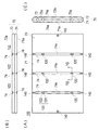
図1は、本発明の第1の実施形態に係る電池モジュール60を示す正面図である。図2は、ラミネート外装電池11の一例を示す斜視図、図3(A)は、同ラミネート外装電池11を示す平面図、図3(B)は、図3(A)の3B−3B線に沿う断面図である。図4(A)〜(C)は、それぞれ、図1に示される電池収納ケース61を示す正面図、上面図および側面図、図5は、図4(A)の5−5線に沿う断面図である。
(First embodiment)
FIG. 1 is a front view showing a
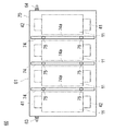
図1を参照して、電池モジュール60は、電池収納ケース61内にラミネート外装電池11を収納して構成されている。電池収納ケース61を、以下、単に、「ケース61」とも称する。ラミネート外装電池11を任意の個数直並列に接続することによって、所望の電流、電圧、容量に対応できる電池モジュール60を提供することができる。ケース61は空冷式であり、電池モジュール60の使用時には、冷却風がケース61の周囲を通過する。
Referring to FIG. 1, the
図示する電池モジュール60では、ラミネート外装電池11を前後方向(図1の紙面に直交する方向)に2枚、幅方向(図1の左右方向)に4枚並べた計8枚を直列に接続して電池群を構成し、この電池群をケース61に収納してある。なお、図示省略するが、ケース61内でラミネート外装電池11を直並列に接続する際には、スペーサやバスバーのような適当な接続部材が用いられている。
In the illustrated
ケース61の両側面には、電池モジュール60の正極端子63および負極端子64が設けられている。正極端子63は、図示しないリード線を介して、電池群の先頭のラミネート外装電池11の正極電極端子41に電気的に接続されている。負極端子64は、図示しないリード線を介して、電池群の末尾のラミネート外装電池11の負極電極端子42に電気的に接続されている。
A
ケース61内の上部空間および下部空間には、絶縁性のポッティング材、例えば、ウレタン系の低温熱硬化型ポッティング材が充填されている。ポッティング材を充填して接続回路を絶縁封止および固定することにより、各ラミネート外装電池11のガタが抑えられ、電極端子41、42自体が破損したり、スペーサやバスバーなどを用いた電気的な接続回路が断線したりすることが防止される。
The upper space and the lower space in the
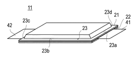
図2および図3を参照して、ラミネート外装電池11は、可撓性を有する一対のラミネートフィルム21、22と、ラミネートフィルム21、22の外周縁部23を熱融着することにより密封される発電要素31と、発電要素31に一端が電気的に接続された正負の電極端子41、42と、を有している。電極端子41、42のそれぞれは、発電要素31の対向する端面に接続されている。各電極端子41、42の他端は、ラミネートフィルム21、22の外周縁辺から外部に突出している。
2 and 3, the laminated
図示するラミネート外装電池11は、例えば、リチウムイオン二次電池であり、正極板、負極板およびセパレータを順に積層した積層型の発電要素31がラミネートフィルム21、22により密封されている。積層型の発電要素31を備えるラミネート外装電池11にあっては、電極板間の距離を均一に保って電池性能の維持を図るために、発電要素31に圧力を掛けて押さえる必要がある。このため、ラミネート外装電池11は、発電要素31が押さえつけられるようにケース61に収納されている。
The illustrated laminated
前記ラミネートフィルム21、22は、一般的に、2層以上のシートからなる複合シートであり、内方から表面にかけて順に、熱融着されるシール層24と、アルミラミネートフィルムなどの金属層25と、外装を形成する樹脂層26とを有している。シール層24は、熱融着性の樹脂から形成されている。熱融着性の樹脂材料としては、たとえば、ポリプロピレン(PP)、ポリエチレン(PE)などの熱可塑性樹脂材料が適用される。
The
各ラミネートフィルム21、22は、略矩形状を有し、発電要素31を挟み込むように被覆している。一対のラミネートフィルム21、22は、発電要素31の外側からフィルム端部にかけて、シール層24同士が熱融着によって接合されている。電極端子41、42が突出する部分においては、電極端子41、42をなすアルミ板とシール層24とが熱融着によって直接接合されている。外周縁部23の4辺23a〜23dのうち電極端子41、42が突出する2つの辺23a、23cは、電極端子41、42を介して振動が伝達されて微小隙間が発生し易い箇所である。このため、一般的に、電極端子41、42が突出する辺23a、23cにおける引裂き強度は、他の2つの辺23b、23dにおける引裂き強度に比べて高めてある。辺23a、23cにおける引裂き強度は、例えば、電極端子41、42に表面処理を施したり、シール層24の材質を調整したり、熱融着の手法や条件を変えたりすることによって、辺23b、23dよりも高められている。熱融着された外周縁部23をシール部23ともいう。
Each of the
過充電などの異常により電池内部でガスが発生した場合において、ガスの圧力が所定の圧力よりも高くなると、ラミネート外装電池11は膨張を開始し、いずれシール部23の4辺23a〜23dのうち引裂き強度が弱い側の辺23bまたは23dの熱融着状態が開裂し、ここからガスが外部に放出されることになる。これにより、ラミネート外装電池11の破裂などの事態が防止され、異常時の信頼性が向上する。辺23bまたは23dが熱融着状態を開裂する所定の圧力は、シール部23の幅や熱融着条件などを変えることで適宜設定可能であるが、例えば、約1kgf/cm2である。
In the case where gas is generated inside the battery due to an abnormality such as overcharge, when the gas pressure becomes higher than a predetermined pressure, the laminate-sheathed
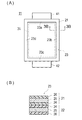
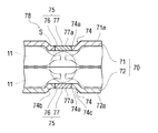
図4および図5を参照して、第1の実施形態に係るケース61は、可撓性を有するラミネートフィルム21、22によって発電要素31が密封されたラミネート外装電池11を収納するために好適に用いられる。当該ケース61は、概説すれば、ラミネート外装電池11を密閉状態で収納するための略扁平形状を呈するケーシング70と、断面凹形状を有し、ケーシング70の表面から窪むように形成された凹部74と、凹部74を形成する壁面に配置され、ラミネート外装電池11から異常時にケーシング70内に放出されたガスを外部に放出する開裂弁75(ガス放出機構に相当する)と、を有している。以下、詳述する。
With reference to FIGS. 4 and 5, the
前記ケーシング70は、図4(A)〜(C)に示すように、突き合わされて内部に電池収納空間を形成する第1と第2のケーシング71、72を含んでいる。第1と第2のケーシング71、72は、扁平な矩形形状を有し(図4(A)参照)、上端部および下端部は円弧形状に形成されている(図4(C)参照)。ケーシング70の寸法は適宜選択できる。図示例のケーシング70は、ラミネート外装電池11を前後方向に2枚、幅方向に4枚並べた計8枚を収納するための寸法を備えている。第1と第2のケーシング71、72の材質は、金属材料や樹脂材料など適宜の材料を選択し得るが、冷却性および強度の観点からは、アルミやステンレスなどの金属材料から形成するのが好ましい。第1と第2のケーシング71、72は、図示しない締結ねじにより相互に締結され、電池収納空間を密閉状態とし、水分からシールしている。第1と第2のケーシング71、72の突き合わせ面に、シール材を塗布したり、パッキンなどのシール部材を介装したりして、水密性を高めてもよい。突き合わせた第1と第2のケーシング71、72の両側面には、円形状の通孔73が形成される。この通孔73に、電池モジュール60の正極端子63および負極端子64が配置される(図1参照)。
As shown in FIGS. 4A to 4C, the
なお、説明の便宜上、第1と第2のケーシング71、72の表面71a、72aを、総称して、ケーシング表面71a、72aとも言い、第1ケーシング71の表面71aをケーシング70の「前面71a」と、第2ケーシング72の表面72aをケーシング70の「背面72a」とも言う。
For convenience of explanation, the
前記凹部74は、図4に示すように、図示例では第1と第2のケーシング71、72のそれぞれに3列上下方向に伸びて形成されている。各凹部74は、幅方向に隣接する電池同士の間に位置する箇所に設けられている。凹部74は、図5に示すように、断面凹形状を有し、第1と第2のケーシング71、72の表面71a、72aから窪んで形成されている。凹部74は、プレス加工により形成されている。凹部74の幅および深さの寸法は適宜選択できるが、一例を挙げれば、幅は6mm〜8mm程度、深さは1mm〜2mm程度である。凹部74の長さは、第1と第2のケーシング71、72の上端部および下端部の円弧部分に至る長さである。この凹部74の少なくとも一の端部は、凹部74を形成したケーシング表面71a、72aが他の部材(図4(B)に2点鎖線で示される)に密着した状態においても、雰囲気空間と連通している。
As shown in FIG. 4, the
前記開裂弁75は、凹部74を形成する壁面に配置されている。図示例では、凹部74の底壁面74aに、開裂弁75を配置してある。開裂弁75は、各列の凹部74ごとに、2個ずつ配置してある。この開裂弁75は、図5に示すように、凹部74の底壁面74aに開口したガス放出孔76と、ガス放出孔76を封止するとともにケーシング70の内圧が所定の圧力に達したときにガス放出孔76を開放する封止板77と、を有している。ガス放出孔76は、長孔形状を有している。封止板77は、シール材、金属材料または樹脂材料など適宜の材料から形成され、ガス放出孔76を封止するように、接着剤や熱融着などの接合手段によって取り付けられている。ラミネート外装電池11から異常時にケーシング70内に放出されたガスが所定の圧力に達したときには、封止板77が開裂あるいは破裂し、ケーシング70内に充満したガスをガス放出孔76から外部に放出する。これにより、ケース61の異常膨張や破損などが防止される。開裂弁75が作動する所定の圧力は、封止板77の材質や肉厚、使用する接着剤の種類、熱融着条件などを変えることにより適宜設定可能であるが、ラミネート外装電池11のシール部23が開裂する圧力と同じ圧力、例えば、約1kgf/cm2である。
The
開裂弁75を配置する凹部74の壁面は、水分が滞留しないことが好ましい。封止板77の腐食を防止し、開裂弁75の正常な作動と、ケース61の水密性とを長期にわたって維持するためである。このため、封止板77の表面77aは、ガス放出孔76を開口した底壁面74aの表面と面一に形成してある。このようにすれば、封止板77の周囲に水分が滞留することが抑えられる。
It is preferable that moisture does not stay on the wall surface of the
開裂弁75を、ケーシング70の前面71aおよび/または背面72aに配置する必要性について説明する。ラミネート外装電池11は厚さ方向では押さえつけられてケース61に収納され、さらに、このケース61内の上部空間および下部空間はポッティング材が充填されている。上面および/または下面に開裂弁75を設けた場合には、充填されたポッティング材が通気抵抗となるため、異常時に放出されたガスの圧力が開裂弁75にすぐに作用せず、開裂弁75は、その機能を十分かつ迅速に発揮できなくなる。したがって、ラミネート外装電池11から異常時に放出されたガスの主な通路としては、幅方向に隣接する電池同士の間に形成される隙間空間S(図5を参照)を利用するのが好ましい。この隙間空間Sは、ラミネート外装電池11のシール部23の辺23b、23dに臨んでいるので、ラミネート外装電池11から放出されたガスが直接導かれる空間でもある。したがって、幅方向に隣接する電池同士の間に形成される隙間空間Sを、異常時にラミネート外装電池11から放出されたガスの通路78に利用するのが好ましいと言える。そこで、このガス通路78に開裂弁75を直接連通させるために、開裂弁75を、ケーシング70の前面71aおよび/または背面72aに配置する必要がある。
The necessity of disposing the
開裂弁75を、凹部74を形成する壁面に配置する必要性について説明する。図示例のケーシング70はラミネート外装電池と接触面積を確保して冷却効果を高める目的から厚さが比較的薄い扁平な形状を有しているので、ラミネート外装電池11から異常時に放出されたガスやラミネート外装電池のガス放出前の膨張によって変形ないし膨出する度合いは、上下面および左右側面に比べて、前面71aおよび背面72aの方が大きい。このため、前面71aおよび/または背面72aの平坦な表面上に開裂弁75を直接配置すると、ラミネート外装電池11から異常時に放出されたガスによって前面71aおよび/または背面72aが膨らんで、開裂弁75が他の部材に押し付けられてしまい、ガスを外部に放出する機能を十分に発揮し得なくなる。「他の部材」は、例えば、隙間を隔てて積層状態に配置された他の電池モジュールなどもあり、限られたスペースに搭載するにあたっては車両等の構造体に隣接して配置された場合である。そこで、ラミネート外装電池11から異常時に放出されたガスによってケーシング70自体が多少変形したとしても、ケース61内に充満したガスを外部に放出することができるようにするために、開裂弁75を、凹部74を形成する壁面に配置する必要がある。
The necessity of arranging the
図示例にあっては、ケーシング70の左右側面に、開裂弁75と同様に構成される開裂弁75aを設けてある(図4(C)参照)。ケーシング70の左右側面は、前述したように、変形の度合いが前面71aおよび/または背面72aに比べて小さいので、開裂弁75aが他の部材に押し付けられることが事実上生じない。このため、開裂弁75aは、左右側面の平坦な表面上に直接配置してある。
In the example of illustration, the
なお、ケーシング70を耐圧容器とし、異常時にラミネート外装電池11からケーシング70内に放出されたガスの圧力に抗して変形しないようにすることも考えられる。しかしながら、耐圧容器とするためには、ケーシング70の肉厚、第1と第2のケーシング71、72を締結する箇所や構造などを改変しなければならず、ケーシング70が大型となり重量も重くなることから現実的な解決策にはなり得ない。本実施形態では、電池モジュール60の小型軽量化を図る観点から、ケーシング70を耐圧容器としていない。このため、異常時にラミネート外装電池11からガスが放出されると、これと同時に、ケーシング70の一部、特に、前面71aおよび背面72aが膨れてくる。
It is also conceivable to use the
次に、開裂弁75の作用を説明する。
Next, the operation of the
過充電などの異常により、ラミネート外装電池11の内部でガスが発生することがある。このガスによる応力は、熱融着されたシール部23に作用する。電池内のガス圧力が所定の圧力に達すると、シール部23の辺23bまたは23dの熱融着状態が開裂し、ここからガスが外部に放出される。異常時にラミネート外装電池11からガスが放出される向きは、隙間空間Sに向かう方向である。ここで、シール部23は、発電要素31を囲繞する部分に比べると厚さが非常に薄いため、ラミネート外装電池11を厚さ方向で押さえつけてケース61に収納した状態でも、シール部23の周辺には隙間が必ず存在する。したがって、異常時に電池内で発生したガスは、開裂したシール部23の部分を通って外部に必ず放出されるため、ラミネート外装電池11の破裂などの事態が防止され、異常時の信頼性が向上する。
Due to abnormalities such as overcharge, gas may be generated inside the
異常時にラミネート外装電池11から放出されたガスによって、ケーシング70の一部、特に、前面71aおよび背面72aも同時に膨れてくる。そして、ケース61の内圧が所定の圧力に達すると、開裂弁75または開裂弁75aの封止板77が開裂あるいは破裂して、ケーシング70内に充満したガスをガス放出孔76から外部に放出する。これにより、ケース61の異常膨張や破損などが防止される。
A part of the
本実施形態の電池モジュール60では、隙間空間Sに向けて放出されたガスは、当該隙間空間Sにより構成されるガス通路78を通り、当該ガス通路78に直接連通している開裂弁75にすぐに至る。このため、開裂弁75の機能を十分かつ迅速に発揮させることができ、ケース61が破損する事態を確実に防止することが可能となる。
In the
ここで、開裂弁75は凹部74の底壁面74aに配置してあるので、ケーシング70の前面71aおよび/または背面72aが膨らんだとしても、開裂弁75が他の部材に押し付けられてしまう事態が発生しない。したがって、開裂弁75は、ガスを外部に放出する機能を十分に発揮することになる。また、開裂弁75は、凹部74の底壁面74aに配置してあるので、比較的大きな開口面積を備える開裂弁75とすることができ、異常時のガスを迅速に放出できる。
Here, since the
また、凹部74を形成したケーシング70表面が他の部材に密着した状態においても、凹部74の少なくとも一の端部が雰囲気空間と連通するようにしてあるため、開裂弁75は、ガスを外部に放出する機能をより一層十分に発揮する。
Even when the surface of the
また、封止板77の表面77aを底壁面74aの表面と面一に形成したので、凹部74の底壁面74aの上に水分が滞留することを抑えて封止板77の腐食を防止でき、開裂弁75の正常な作動と、ケース61の水密性とを長期にわたって維持することが可能となる。
Further, since the
以上説明したように、第1の実施形態のケース61は、ラミネート外装電池11を密閉状態で収納するための略扁平形状を呈するケーシング70と、断面凹形状を有し、ケーシング70の表面71a、72aから窪むように形成された凹部74と、凹部74を形成する壁面74aに配置され、ラミネート外装電池11から異常時にケーシング70内に放出されたガスを外部に放出するガス放出機構としての開裂弁75を有しているので、ラミネート外装電池11から異常時に放出されたガスによってケーシング70自体が多少変形したとしても、開裂弁75はケース61内に放出されたガスを外部に放出することができ、異常時の信頼性を向上することが可能となるという効果を奏する。
As described above, the
凹部74を形成したケーシング表面71a、72aが他の部材に密着した状態においても、凹部74の少なくとも一の端部は、雰囲気空間と連通しているので、ラミネート外装電池11から異常時に放出されたガスを雰囲気空間に確実に放出でき、異常時の信頼性をさらに向上することができる。
Even in a state where the casing surfaces 71a and 72a in which the
開裂弁75は、凹部74の底壁面74aに配置されているので、比較的大きな開口面積を備える開裂弁75とすることができ、異常時のガスを迅速に放出できる。
Since the
開裂弁75は、凹部74の壁面に開口したガス放出孔76と、ガス放出孔76を封止するとともにケーシング70の内圧が所定の圧力に達したときにガス放出孔76を開放する封止板77と、を有するので、開裂弁75を簡便に形成することができる。
The
封止板77の表面77aは、ガス放出孔76を開口した凹部壁面74aの表面と面一に形成されているので、水分が滞留することを抑えて開裂弁75の腐食を防止でき、開裂弁75の正常な作動と、ケース61の水密性とを長期にわたって維持することが可能となる。
Since the
さらに、ケース61内にラミネート外装電池11を収納して電池モジュール60を構成すると、高容量、高出力の電池モジュール60を形成することができる。また、電池モジュール60を構成する際に開裂弁75を設ける位置を容易に設定でき、ケース61や開裂弁75の設計が容易になる。
Furthermore, when the
なお、凹部74の底壁面74aに開裂弁75を配置した実施形態について図示したが、底壁面74aから立ち上がる対向する側壁面74b、74c(図5参照)の一方または両方に開裂弁75を配置することも可能である。
In addition, although illustrated about embodiment which has arrange | positioned the
第1ケーシング71の凹部74と、第2ケーシング72の凹部74とを向かい合う位置に形成した実施形態について図示したが(図5参照)、これは、前後方向(図5においては上下方向)に並べたラミネート外装電池11が、幅方向(図5においては左右方向)にずれていないからである。したがって、前側のラミネート外装電池11と後側のラミネート外装電池11とを幅方向にずらしてケース61内に収納する形態の場合には、当然ながら、第1ケーシング71の凹部74と、第2ケーシング72の凹部74とは向かい合わない。このような形態であっても、凹部74の壁面に配置した開裂弁75に所定の機能を発揮させることができる。
Although the embodiment in which the
また、電池モジュール60は、実施形態で説明したものに制限されるべきものではなく、従来公知のものを適宜採用することができる。電池モジュール60には、使用用途に応じて、各種計測機器や制御機器類、例えば、電池電圧を監視するために電圧計測用コネクタを設けてもよい。さらに、ラミネート外装電池11同士を連結するためには、超音波溶接、熱溶接、レーザ溶接または電子ビーム溶接により、または、リベットを用いて、またはカシメの手法を用いて、連結してもよい。
Moreover, the
また、正負の電極端子41、42のそれぞれが発電要素31の対向する端面に接続されている形態のラミネート外装電池11を示したが、正負の電極端子41、42の両者が発電要素31の一の端面に接続されている形態のラミネート外装電池を収納する場合にも本発明は適用可能である。
In addition, the laminated
(第2の実施形態)
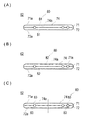
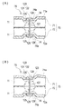
図6(A)〜(C)は、第2の実施形態に係るケース62の要部を示す断面図である。
(Second Embodiment)
6A to 6C are cross-sectional views showing the main parts of the
第2の実施形態は、開裂弁75を配置する凹部74の壁面に、水分を滞留させない排水手段80を施したものである。水分を滞留させない理由は、前述したように、開裂弁75の腐食を防止することにより、開裂弁75の正常な作動と、ケース62の水密性とを長期にわたって維持するためである。
In the second embodiment, the drainage means 80 that does not retain moisture is applied to the wall surface of the
前記排水手段80は、開裂弁75を配置する凹部74の壁面を傾斜面81〜83に形成することにより構成されている。凹部74の底壁面74aに開裂弁75を配置し、かつ、前面71aおよび背面72aが水平方向をなすようにケース62を配置する場合を例に挙げれば、凹部74の底壁面74aを傾斜面に形成すればよい。具体的には、図6(A)(B)に示すように、凹部74の長手方向に沿う一の端部から他方の端部まで傾斜面81、82とする形態、図6(C)に示すように、凹部74の長手方向に沿う略中央部分から各端部に向けて下る傾斜面83とする形態などが例示できる。図6(A)では、上位側の第1ケーシング71では図中左側へ下る傾斜面81とされ、下位側の第2ケーシング72では図中右側へ下る傾斜面81とされている。図6(B)では、第1と第2のケーシング71、72はともに図中右側へ下る平行な傾斜面82とされている。
The drainage means 80 is configured by forming the wall surface of the
このように、凹部74の底壁面74aを傾斜面81〜83に形成することにより、水分は傾斜面81〜83に沿って流れて排出されるので、底壁面74aに水分は滞留しない。
したがって、開裂弁75の腐食を防止することにより、開裂弁75の正常な作動と、ケース62の水密性とを長期にわたって維持することができる。
In this way, by forming the
Therefore, by preventing the
以上説明したように、第2の実施形態によれば、開裂弁75を配置する凹部74の壁面は、水分を滞留させない排水手段80が施されているので、水分が滞留することを抑えて開裂弁75の腐食を防止でき、開裂弁75の正常な作動と、ケース62の水密性とを長期にわたって維持することが可能となる。
As described above, according to the second embodiment, the wall surface of the
排水手段80は凹部74の壁面を傾斜面81〜83に形成することにより構成されているので、排水手段80を容易に形成することができる。
Since the drainage means 80 is formed by forming the wall surface of the
なお、排水手段80は、第2の実施形態のように、凹部74の壁面を傾斜面81〜83に形成して構成する場合に限定されるものではない。例えば、凹部74の壁面に撥水剤を塗布することにより、排水手段80を構成してもよい。この場合も、同様に、水分が滞留することを抑えて開裂弁75の腐食を防止でき、開裂弁75の正常な作動と、ケース62の水密性とを長期にわたって維持することが可能となる。
The drainage means 80 is not limited to the case where the wall surface of the
また、傾斜面81〜83と撥水剤の塗布とを組み合わせて、排水手段80を構成することもできる。
Further, the drainage means 80 can be configured by combining the
さらに、凹部74の底壁面74aがフラットである第1の実施形態で説明したケース61を、前面71aおよび背面72aが水平方向に対して傾斜するようにケース61を配置すれば、凹部74の底壁面74aが実質的に傾斜面となる。このように配置することにより、排水手段80を構成してもよい。
Furthermore, if the
(第3の実施形態)
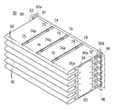
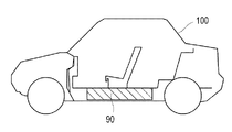
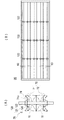
図7は、本発明の第3の実施形態に係る組電池90を示す斜視図、図8は、組電池90が搭載された車両100を模式的に表す図である。
(Third embodiment)
FIG. 7 is a perspective view showing an assembled
第3の実施形態は、第1の実施形態の電池モジュール60を、電気的に並列および/または直列に複数個接続して組電池90を構成したものである。組電池90とすることで、使用目的ごとの電池容量や出力に対する要求に、新たに専用の電池モジュール60を作製することなく、比較的安価に対応することが可能になる。
In the third embodiment, a
図7に示したように、電池モジュール60を6組並列に接続して組電池90とするには、各電池モジュール60の正極端子63を、外部正極端子部91aを有する正極端子連結板91を用いて電気的に接続し、負極端子64を、外部負極端子部92aを有する負極端子連結板92を用いて電気的に接続する。また、各ケース61の両側面に設けられた各ネジ孔部(図示せず)に、該ネジ孔部に対応する開口部を有する連結板93を固定ネジ94で固定し、各電池モジュール60同士を連結する。各電池モジュール60の正極端子63および負極端子64は、それぞれ正極および負極絶縁カバー95、96により保護され、適当な色、例えば、赤色と青色に色分けすることで識別されている。上位の電池モジュール60と下位の電池モジュール60との間には、冷却風を通過させるための隙間が設けられている。
As shown in FIG. 7, in order to connect six
このように、電池モジュール60を複数直並列接続されてなる組電池90は、一部の電池11や電池モジュール60が故障しても、その故障部分を交換するだけで修理が可能である。
As described above, the assembled
組電池90を、電気自動車(EV)に搭載するには、図8に示すように、電気自動車100の車体中央部の座席下に搭載する。座席下に搭載すれば、車内空間およびトランクルームを広く取ることができるからである。なお、電池を搭載する場所は、座席下に限らず、後部トランクルームの下部でもよい。EVやFCV(燃料電池自動車)のようにエンジンを搭載しない車両であれば、エンジンが一般的に搭載される車両前方に設置することもできる。
In order to mount the assembled
さらに、ラミネート外装電池11は金属製の外装缶を用いる電池と比較して軽量であるため、組電池90の軽量化、引いては車両100全体の軽量化を通して、EV車などの走行距離の向上に寄与することができる。
Furthermore, since the laminate-clad
なお、本発明では、組電池90だけではなく、使用用途によっては、電池モジュール60を搭載したり、組電池90と電池モジュール60とを組み合わせて搭載したり、電池モジュール60のみを搭載したり、一のラミネート外装電池11を単電池として搭載したりしてもよい。また、本発明のラミネート外装電池11、電池モジュール60または組電池90を搭載することのできる車両100としては、EV、FCV、ハイブリッドカー(HEV)が好ましいが、これらに制限されるものではない。
In the present invention, not only the assembled
以上説明したように、電池モジュール60を、電気的に並列および/または直列に複数個接続して組電池90を構成すると、その組電池90は、基本となる電池モジュール60の数や接続方法を変えるだけで、種々の容量や電圧の組電池90を得ることができる。
As described above, when the assembled
また、電池モジュール60または組電池90を搭載することによって、車両100の重量を極度に増加させることがなくなり、また、車両100の有効スペースを極端に狭めることがなくなり、燃費、走行性能に優れた車両100が提供できる。
Further, by mounting the
(第4の実施形態)
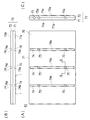
図9(A)〜(C)は、本発明の第4の実施形態に係る電池収納ケース110を示す正面図、上面図および側面図である。図10(A)(B)は、図9(A)の10−10線に沿う断面図であり、第4の実施形態の作用の説明に供する図である。なお、第1の実施形態と共通する部材には同じ符号を付し、その説明は省略する。
(Fourth embodiment)
FIGS. 9A to 9C are a front view, a top view, and a side view showing a
第4の実施形態は、ガス放出機構としての開裂弁120を、ラミネート外装電池11が異常時に膨張することを利用して開裂させている。この点において、ケーシング70の内圧を利用して開裂弁75を開裂させるようにした第1〜第3の実施形態と相違している。
In the fourth embodiment, the
第4の実施形態の開裂弁120は、概説すれば、凹部74の壁面に設けられるとともに変形することによってガス放出部123を形成する脆弱部121と、ケーシング70が膨張変形するのに伴う力を脆弱部121に伝達しつつ脆弱部121の変形を抑制するための固定部122と、を有している。そして、ラミネート外装電池11が異常時に膨張することによってケーシング70が膨張変形したときに伴う力を、固定部122を介して脆弱部121に伝達し、当該脆弱部121を変形させてガス放出部123を形成するようにしてある。
In summary, the
脆弱部121の強度は、凹部74の壁面自体の強度よりも低下させることが必要であるが、水密性を保つために必要な強度以上であって、異常膨張したラミネート外装電池11がケース110に加える機械的な圧力以下で変形する強度に設定されている。
The strength of the
図示する脆弱部121は、凹部74の壁面に開口したガス放出孔124と、ガス放出孔124を封止する封止板125との境界面126によって構成され、ガス放出部123は、ガス放出孔124の周囲の壁面および/または封止板125が変形することによって形成される。封止板125は、第1の実施形態と同様に、シール材、金属材料または樹脂材料など適宜の材料から形成され、ガス放出孔124を封止するように、接着剤や熱融着などの接合手段によって取り付けられている。
The
ケーシング70は、脆弱部121が設けられる側の一の面(例えば、前面71a)と、ラミネート外装電池11を収納する空間を隔てて一の面の反対側に位置する他の面(例えば、背面71b)と、を含んでいる。固定部122は、脆弱部121をケーシング70の他の面に対して固定するための部材127を含んでいる。固定するための部材127は、封止板125の前後方向(図10においては上下方向)の移動を規制するシャフト部材、例えば、リベットやボルトなどからなる。シャフト部材127の両端には係止片128が設けられている。かかる構成により、第1ケーシング71側の封止板125はシャフト部材127を介して反対側の第2ケーシング72に対して相対的に固定され、第2ケーシング72側の封止板125はシャフト部材127を介して反対側の第1ケーシング71に対して相対的に固定されることになる。
The
異常時にラミネート外装電池11が膨張した場合には、ケーシング70を膨張変形させる力(図10においては上下に押し広げる力)が生じる。第1の実施形態では、ケーシング70が膨張変形したときの応力は、第1と第2のケーシング71、72を相互に締結する締結ねじ140(図9(A)参照)のみに集中する。これに対して、第4の実施形態にあっては、ケーシング70が膨張変形したときの応力は、締結ねじ140のみならず、シャフト部材127を含む固定部122に対しても集中する。この応力は、固定部122を介して、強度が低下している脆弱部121、すなわちガス放出孔124と封止板125との境界面126に伝達される。
When the laminate-cased
ケーシング70の膨張変形量が比較的小さく、脆弱部121に作用する力が比較的小さい場合には、脆弱部121は、作用する力に十分に抗し、変形しない。ケーシング70の膨張変形量が大きくなり、脆弱部121に作用する力が脆弱部121の強度よりも大きくなると、脆弱部121は、作用する力に抗することができずに変形する。これにより、ガス放出部123が開放形成される。図10(B)には、ガス放出孔124の周囲の壁面が変形して、ガス放出部123が開放形成された状態が示されている。ラミネート外装電池11からケーシング70内に放出されたガスは、ガス放出部123を通って外部に放出される。ガス放出部123が形成される以前にラミネート外装電池11から異常時にケーシング70内にガスが放出されることもあるが、ケーシング70内に充満していたガスも、ガス放出部123を通って外部に放出される。これらにより、ケース110の異常膨張や破損などが防止される。
When the expansion deformation amount of the
第4の実施形態の開裂弁120は、ラミネート外装電池11が異常時に膨張することを利用しており、ケーシング70の内圧に影響を受けることなく、ケース110の変形量に基づいて開裂弁120を開裂させることができる。ケーシング70の内圧に基づいて開裂弁75を開裂させる場合には、開裂弁75が開裂する条件、つまり作動圧力に多少のバラツキが生じ得る。これに比べて、ケース110の変形量に基づいて開裂弁120を開裂させる場合には、開裂弁120を開裂させる際のケース110の変形量を比較的容易に一律に保つことができ、開裂弁120が開裂する条件にバラツキが生じ難い。
The
以上説明したように、第4の実施形態によっても、第1〜第3の実施形態と同様に、異常時にラミネート外装電池11が膨張することによってケーシング70自体が多少変形したとしても、開裂弁120はケース110内に放出されたガスを外部に放出することができ、異常時の信頼性を向上することが可能となるという効果を奏する。
As described above, also in the fourth embodiment, as in the first to third embodiments, even if the
また、ガス放出機構としての開裂弁120はラミネート外装電池11が異常時に膨張することを利用して開裂するため、開裂弁120を開裂させる際のケース110の変形量を比較的容易に一律に保つことができ、開裂弁120が開裂する条件にバラツキが生じ難い。
Further, since the
また、第3の実施形態のように電池モジュール60を積み重ねて組電池とする場合(図7参照)、図11(A)(B)に示すように、隣接する電池モジュール60の固定部122同士を図中上下方向に連結することで、モジュールの連結部材93に代用することもできる。
When the
なお、図中上下の封止板125を連結するようにシャフト部材127を設けた場合を図示したが、図中上側または下側の一方のみの封止板125を固定する形態でもよい。
Although the case where the
また、封止板125にシャフト部材127を貫通させた場合を図示したが、固定部122は、ケーシング70が膨張変形するのに伴う力を脆弱部121に伝達しつつ脆弱部121の変形を抑制するものであればよい。したがって、固定部122を、封止板125を貫通させずに、当該封止板125に近接して設けてもよい。
Although the case where the
図12(A)は、第4の実施形態における開裂弁120と同タイプの開裂弁120aを示す断面図である。
FIG. 12A is a cross-sectional view showing a
脆弱部121は、ケーシング70とは別体の部材である封止板125を用いて構成する場合に限定されない。例えば、図12(A)に示すように、脆弱部121は、凹部74の壁面の一部に形成した薄肉部130によって、ケーシング70の一部として構成することもできる。この場合のガス放出部131は、薄肉部130が変形破断することによって形成される。薄肉部130は、ケーシング70に溝または切り欠きを設けて、強度が弱い部分となるようにしたものである。薄肉部130は、固定部122の周囲に形成されている。但し、上述したのと同様に、固定部122を、薄肉部130に近接して設けてもよい。また、薄肉部130は、図12(B)〜(D)に示すように、ケーシング70の内側(図12(B))、外側(図12(C))、内側外側の両方(図12(D))に設けるようにしてもよい。なお、図12(B)〜(D)には、第1ケーシング71を示してある。
The
かかる構成の開裂弁120aも、上述した開裂弁120と同様の作用効果を奏する。
The
(その他の変形例)
第1、第4の実施形態で説明した電池モジュール60にあっては、複数個のラミネート外装電池11をケース61内に収納してあるが、当然ながら、1個のラミネート外装電池11をケース内に収納した電池モジュールとすることも可能である。
(Other variations)
In the
11 ラミネート外装電池、
21、22 ラミネートフィルム、
23 外周縁部、
31 発電要素、
60 電池モジュール、
61、62 電池収納ケース、
70 ケーシング、
71、72 第1と第2のケーシング、
71a 第1ケーシングの表面、ケーシング表面、ケーシングの前面、一の面、
72a 第2ケーシングの表面、ケーシング表面、ケーシングの背面、他の面、
74 凹部、
74a 凹部の底壁面、
75 開裂弁(ガス放出機構)、
75a 開裂弁、
76 ガス放出孔、
77 封止板、
77a 封止板の表面、
78 ガス通路、
80 排水手段、
81〜83 傾斜面、
90 組電池、
100 車両、
110 電池収納ケース、
120、120a 開裂弁(ガス放出機構)、
121 脆弱部、
122 固定部、
123 ガス放出部、
124 ガス放出孔、
125 封止板、
126 境界面、
127 シャフト部材(脆弱部をケーシングの他の面に対して固定するための部材)、
130 薄肉部、
131 ガス放出部、
S 隙間空間。
11 Laminated exterior battery,
21, 22 Laminated film,
23 outer periphery,
31 power generation elements,
60 battery module,
61, 62 Battery storage case,
70 casing,
71, 72 first and second casings,
71a surface of the first casing, casing surface, front surface of the casing, one surface,
72a The surface of the second casing, the casing surface, the back surface of the casing, the other surface,
74 recess,
74a The bottom wall surface of the recess,
75 Cleavage valve (gas release mechanism),
75a cleavage valve,
76 outgassing holes,
77 sealing plate,
77a The surface of the sealing plate,
78 Gas passageway,
80 drainage means,
81-83 inclined surface,
90 battery packs,
100 vehicles,
110 battery storage case,
120, 120a cleavage valve (gas release mechanism),
121 vulnerable part,
122 fixing part,
123 gas discharge part,
124 outgassing holes,
125 sealing plate,
126 interface,
127 shaft member (member for fixing the weakened portion to the other surface of the casing),
130 Thin part,
131 gas discharge part,
S Clearance space.
Claims (15)
ラミネート外装電池を密閉状態で収納するための略扁平形状を呈するケーシングと、
断面凹形状を有し、前記ケーシングの表面から窪むように形成された凹部と、
前記凹部を形成する壁面に配置され、前記ラミネート外装電池から異常時に前記ケーシング内に放出されたガスを外部に放出するガス放出機構と、を有してなる電池収納ケース。 A battery storage case for storing a laminated exterior battery in which a power generation element is sealed by a flexible laminate film,
A casing having a substantially flat shape for storing the laminate-sheathed battery in a sealed state;
A concave portion having a concave cross-section and formed to be recessed from the surface of the casing;
A battery storage case, comprising: a gas release mechanism that is disposed on a wall surface that forms the concave portion and discharges the gas released from the laminated exterior battery into the casing in an abnormal state to the outside.
前記ガス放出部は、前記ガス放出孔の周囲の壁面および/または前記封止板が変形することによって形成されることを特徴とする請求項9に記載の電池収納ケース。 The fragile portion is constituted by a boundary surface between a gas discharge hole opened in the wall surface of the recess and a sealing plate for sealing the gas discharge hole,
The battery storage case according to claim 9, wherein the gas discharge part is formed by deformation of a wall surface around the gas discharge hole and / or the sealing plate.
前記ガス放出部は、前記薄肉部が変形破断することによって形成されることを特徴とする請求項9に記載の電池収納ケース。 The fragile portion is constituted by a thin portion formed on a part of the wall surface of the recess,
The battery storage case according to claim 9, wherein the gas discharge part is formed by deforming and breaking the thin part.
前記固定部は、前記脆弱部を前記ケーシングの前記他の面に対して固定するための部材を含んでいることを特徴とする請求項9に記載の電池収納ケース。 The casing includes one surface on the side where the fragile portion is provided, and another surface located on the opposite side of the one surface across a space for storing the laminated exterior battery,
The battery storage case according to claim 9, wherein the fixing portion includes a member for fixing the fragile portion to the other surface of the casing.
Priority Applications (4)
| Application Number | Priority Date | Filing Date | Title |
|---|---|---|---|
| JP2004190356A JP4635483B2 (en) | 2003-09-29 | 2004-06-28 | Battery storage case, battery module, and assembled battery |
| US10/950,533 US7378179B2 (en) | 2003-09-29 | 2004-09-28 | Battery accommodation casing, battery module and assembled battery |
| DE602004030648T DE602004030648D1 (en) | 2003-09-29 | 2004-09-29 | Battery case, battery module and assembled battery |
| EP04023173A EP1519430B1 (en) | 2003-09-29 | 2004-09-29 | Battery accomodation casing, battery module and assembled battery |
Applications Claiming Priority (2)
| Application Number | Priority Date | Filing Date | Title |
|---|---|---|---|
| JP2003338522 | 2003-09-29 | ||
| JP2004190356A JP4635483B2 (en) | 2003-09-29 | 2004-06-28 | Battery storage case, battery module, and assembled battery |
Publications (2)
| Publication Number | Publication Date |
|---|---|
| JP2005129487A JP2005129487A (en) | 2005-05-19 |
| JP4635483B2 true JP4635483B2 (en) | 2011-02-23 |
Family
ID=34197275
Family Applications (1)
| Application Number | Title | Priority Date | Filing Date |
|---|---|---|---|
| JP2004190356A Expired - Fee Related JP4635483B2 (en) | 2003-09-29 | 2004-06-28 | Battery storage case, battery module, and assembled battery |
Country Status (4)
| Country | Link |
|---|---|
| US (1) | US7378179B2 (en) |
| EP (1) | EP1519430B1 (en) |
| JP (1) | JP4635483B2 (en) |
| DE (1) | DE602004030648D1 (en) |
Families Citing this family (40)
| Publication number | Priority date | Publication date | Assignee | Title |
|---|---|---|---|---|
| US20080019120A1 (en) * | 2004-01-27 | 2008-01-24 | Carmen Rapisarda | Lighting systems for attachment to wearing apparel |
| JP2007157678A (en) * | 2005-05-23 | 2007-06-21 | Matsushita Electric Ind Co Ltd | Laminated battery safety mechanism |
| WO2007043510A1 (en) * | 2005-10-14 | 2007-04-19 | Nec Corporation | System for receiving film-coated electric device |
| JP5837271B2 (en) * | 2006-03-30 | 2015-12-24 | 大日本印刷株式会社 | Battery module |
| TWI348778B (en) * | 2006-07-27 | 2011-09-11 | Lg Chemical Ltd | Electrochemical device with high safety at over-voltage and high temperature |
| JP4251204B2 (en) * | 2006-08-31 | 2009-04-08 | 日産自動車株式会社 | Battery module |
| WO2008106949A2 (en) * | 2007-03-05 | 2008-09-12 | Temic Automotive Electric Motors Gmbh | Housing for accommodating a power storage cell |
| JP4788646B2 (en) | 2007-04-26 | 2011-10-05 | トヨタ自動車株式会社 | Power storage device and vehicle |
| JP4780079B2 (en) * | 2007-10-15 | 2011-09-28 | ソニー株式会社 | Battery pack and manufacturing method thereof |
| US8318333B2 (en) * | 2007-10-15 | 2012-11-27 | Sony Corporation | Battery pack and method for producing the same |
| EP2279539A1 (en) * | 2008-05-15 | 2011-02-02 | Johnson Controls Saft Advanced Power Solutions LLC | Battery system |
| JP5113034B2 (en) * | 2008-12-26 | 2013-01-09 | Udトラックス株式会社 | Power storage device and module power storage unit |
| US8257848B2 (en) | 2009-01-12 | 2012-09-04 | A123 Systems, Inc. | Safety venting mechanism with tearing tooth structure for batteries |
| US8277965B2 (en) * | 2009-04-22 | 2012-10-02 | Tesla Motors, Inc. | Battery pack enclosure with controlled thermal runaway release system |
| DE102009020185A1 (en) | 2009-05-06 | 2010-11-25 | Continental Automotive Gmbh | Energy storage for hybrid vehicle, has safety device that is dimensioned to release closure of opening of battery case during exceeding pressure threshold value and/or temperature threshold value in battery case |
| US20110052969A1 (en) * | 2009-09-01 | 2011-03-03 | Gm Global Technology Operations, Inc. | Cell tab joining for battery modules |
| US8642205B2 (en) * | 2010-08-09 | 2014-02-04 | Motorola Mobility Llc | Electrochemical battery pack with reduced magnetic field emission and corresponding devices |
| KR101223519B1 (en) | 2010-11-05 | 2013-01-17 | 로베르트 보쉬 게엠베하 | Battery module |
| KR101191660B1 (en) | 2010-11-08 | 2012-10-17 | 에스비리모티브 주식회사 | Battery module |
| KR101401230B1 (en) | 2010-12-24 | 2014-05-28 | 주식회사 엘지화학 | Pouch for secondary battery and Secondary battery using the same |
| KR101261707B1 (en) * | 2011-02-11 | 2013-05-06 | 삼성에스디아이 주식회사 | Battery pack including gas discharging portion |
| US8758931B2 (en) * | 2011-12-02 | 2014-06-24 | Lenovo (Singapore) Pte. Ltd. | Electrochemical cell package |
| JP5958545B2 (en) * | 2012-09-14 | 2016-08-02 | 日産自動車株式会社 | Pressure release structure for in-vehicle battery pack |
| JP2014127692A (en) * | 2012-12-27 | 2014-07-07 | Nippon Chemicon Corp | Capacitor and sealing plate thereof |
| DE102013013752B4 (en) * | 2013-08-17 | 2020-10-15 | Audi Ag | High-voltage battery for an electric drive system of a motor vehicle and method for producing a high-voltage battery |
| KR101904587B1 (en) | 2015-09-01 | 2018-10-04 | 주식회사 엘지화학 | Battery cell and method for manufacturing the same |
| US10388916B2 (en) | 2015-09-18 | 2019-08-20 | Gs Yuasa International Ltd. | Energy storage apparatus |
| JP6778545B2 (en) * | 2016-08-09 | 2020-11-04 | 株式会社東芝 | Batteries |
| US10374211B2 (en) | 2016-09-12 | 2019-08-06 | Cps Technology Holdings Llc | System and method for battery modules having terminal block assemblies with drainage channels |
| CN106816560B (en) * | 2017-02-28 | 2019-06-28 | 安徽江淮汽车集团股份有限公司 | Automobile power cell cabinet |
| JP6935746B2 (en) * | 2017-12-27 | 2021-09-15 | トヨタ自動車株式会社 | In-vehicle battery device |
| JP6680425B1 (en) * | 2018-08-20 | 2020-04-15 | 大日本印刷株式会社 | Valve device, container, power storage device, and valve device mounting method |
| JP7205136B2 (en) * | 2018-09-25 | 2023-01-17 | 大日本印刷株式会社 | Electrical storage device valve device and electrical storage device |
| KR102745195B1 (en) * | 2019-10-08 | 2024-12-23 | 주식회사 엘지에너지솔루션 | Case for secondary battery, secondary battery including the same and method of manufacturing the case for secondary battery |
| JPWO2021256328A1 (en) * | 2020-06-15 | 2021-12-23 | ||
| KR20220026790A (en) | 2020-08-26 | 2022-03-07 | 주식회사 엘지에너지솔루션 | Battery module and battery pack including the same |
| JP7380630B2 (en) * | 2021-03-31 | 2023-11-15 | トヨタ自動車株式会社 | assembled battery |
| KR102929568B1 (en) * | 2021-06-17 | 2026-02-20 | 주식회사 엘지에너지솔루션 | Battery module and battery pack including the same and vehicle including the same |
| KR20250004814A (en) * | 2022-10-20 | 2025-01-08 | 컨템포러리 엠퍼렉스 테크놀로지 (홍콩) 리미티드 | Battery boxes, batteries and electrical devices |
| CN116053684A (en) * | 2023-01-09 | 2023-05-02 | 万华化学集团电池科技有限公司 | A battery aluminum shell and a high-nickel ternary power battery |
Family Cites Families (18)
| Publication number | Priority date | Publication date | Assignee | Title |
|---|---|---|---|---|
| FR2265179B1 (en) * | 1974-03-21 | 1978-01-06 | Accumulateurs Fixes | |
| US4168350A (en) * | 1977-11-23 | 1979-09-18 | General Battery Corporation | Explosion resistant battery cover design |
| JPS61114464A (en) * | 1984-11-09 | 1986-06-02 | Matsushita Electric Ind Co Ltd | Sealed type storage battery |
| US5663007A (en) * | 1994-02-23 | 1997-09-02 | Matsushita Electric Industrial Co., Ltd. | Sealed storage battery and method for manufacturing the same |
| JP2967904B2 (en) * | 1994-03-01 | 1999-10-25 | 本田技研工業株式会社 | Gas exhaust device for battery for electric vehicle |
| KR0138556B1 (en) * | 1995-06-14 | 1998-06-15 | 김광호 | Water-proof case assembly of battery electronic device |
| JP3108360B2 (en) * | 1996-02-15 | 2000-11-13 | 福田金属箔粉工業株式会社 | Battery safety valve element and battery case lid with safety valve |
| US6517967B1 (en) * | 1998-12-15 | 2003-02-11 | Electric Fuel Limited | Battery pack design for metal-air battery cells |
| JP4424773B2 (en) * | 1999-03-19 | 2010-03-03 | 三洋電機株式会社 | Sealed battery |
| JP4224186B2 (en) * | 1999-06-10 | 2009-02-12 | パナソニック株式会社 | Collective secondary battery |
| JP3863351B2 (en) * | 2000-02-18 | 2006-12-27 | 松下電器産業株式会社 | Method for manufacturing prismatic battery and safety mechanism for prismatic battery |
| JP2001345081A (en) | 2000-05-31 | 2001-12-14 | Japan Storage Battery Co Ltd | Non-aqueous electrolyte secondary battery |
| JP4154888B2 (en) * | 2001-12-03 | 2008-09-24 | 日産自動車株式会社 | Battery module and vehicle equipped with battery module |
| JP4494713B2 (en) * | 2001-12-04 | 2010-06-30 | パナソニック株式会社 | Battery pack |
| JP2003272588A (en) * | 2002-03-15 | 2003-09-26 | Nissan Motor Co Ltd | Battery module |
| JP2004178909A (en) * | 2002-11-26 | 2004-06-24 | Matsushita Electric Ind Co Ltd | Sealed secondary battery |
| JP4107163B2 (en) * | 2003-05-28 | 2008-06-25 | トヨタ自動車株式会社 | Assembled battery |
| JP4701658B2 (en) * | 2003-10-14 | 2011-06-15 | 日産自動車株式会社 | Battery module and battery pack |
-
2004
- 2004-06-28 JP JP2004190356A patent/JP4635483B2/en not_active Expired - Fee Related
- 2004-09-28 US US10/950,533 patent/US7378179B2/en not_active Expired - Fee Related
- 2004-09-29 EP EP04023173A patent/EP1519430B1/en not_active Expired - Lifetime
- 2004-09-29 DE DE602004030648T patent/DE602004030648D1/en not_active Expired - Lifetime
Also Published As
| Publication number | Publication date |
|---|---|
| EP1519430B1 (en) | 2010-12-22 |
| DE602004030648D1 (en) | 2011-02-03 |
| JP2005129487A (en) | 2005-05-19 |
| US7378179B2 (en) | 2008-05-27 |
| US20050069759A1 (en) | 2005-03-31 |
| EP1519430A3 (en) | 2008-11-19 |
| EP1519430A2 (en) | 2005-03-30 |
Similar Documents
| Publication | Publication Date | Title |
|---|---|---|
| JP4635483B2 (en) | Battery storage case, battery module, and assembled battery | |
| JP4742492B2 (en) | Battery module, battery pack, and vehicle | |
| JP4701658B2 (en) | Battery module and battery pack | |
| KR101252981B1 (en) | Pouch of improved safety for secondary battery and secondary battery, battery pack using the same | |
| JP5240963B2 (en) | Assembled battery | |
| JP5022031B2 (en) | Film-clad electrical device, frame member, and film-clad electrical device storage system | |
| JP5748380B2 (en) | Battery pack with improved safety | |
| KR102425151B1 (en) | Secondary Battery Pouch-Type Case Having Gas Discharge Port | |
| US8404375B2 (en) | Electrical battery comprising flexible generating elements and a system for the mechanical and thermal conditioning of said elements | |
| JP2008204816A (en) | Assembled battery, vehicle equipped with this assembled battery, and battery-equipped device equipped with this assembled battery | |
| JP2024095749A (en) | Battery packs and electric vehicles | |
| JP4980673B2 (en) | Power storage module | |
| KR20130014253A (en) | Secondary battery having improved safety, and battery pack using the same | |
| JP2006244756A (en) | Film-clad electrical device and film-clad electrical device assembly | |
| CN115917858A (en) | Battery pack and device including the battery pack | |
| KR20220169704A (en) | Battery pack and device including the same | |
| KR101813234B1 (en) | Cell Cover for secondary battery and battery module including the same | |
| CN101821875B (en) | Sealed battery | |
| KR20230020894A (en) | Battery pack and vehicle including the same | |
| JP4239780B2 (en) | Battery pack and manufacturing method thereof | |
| JP4595433B2 (en) | Assembled battery | |
| JP4890795B2 (en) | Film exterior battery and assembled battery in which it is assembled | |
| US20260011814A1 (en) | Battery and electric device | |
| JP4107163B2 (en) | Assembled battery | |
| US20240079712A1 (en) | Traction battery pack dividers and vent path establishing method |
Legal Events
| Date | Code | Title | Description |
|---|---|---|---|
| A621 | Written request for application examination |
Free format text: JAPANESE INTERMEDIATE CODE: A621 Effective date: 20070528 |
|
| A977 | Report on retrieval |
Free format text: JAPANESE INTERMEDIATE CODE: A971007 Effective date: 20100823 |
|
| TRDD | Decision of grant or rejection written | ||
| A01 | Written decision to grant a patent or to grant a registration (utility model) |
Free format text: JAPANESE INTERMEDIATE CODE: A01 Effective date: 20101026 |
|
| A01 | Written decision to grant a patent or to grant a registration (utility model) |
Free format text: JAPANESE INTERMEDIATE CODE: A01 |
|
| A61 | First payment of annual fees (during grant procedure) |
Free format text: JAPANESE INTERMEDIATE CODE: A61 Effective date: 20101108 |
|
| FPAY | Renewal fee payment (event date is renewal date of database) |
Free format text: PAYMENT UNTIL: 20131203 Year of fee payment: 3 |
|
| R150 | Certificate of patent or registration of utility model |
Free format text: JAPANESE INTERMEDIATE CODE: R150 |
|
| LAPS | Cancellation because of no payment of annual fees |