JP4635382B2 - Scroll type expander and refrigeration system - Google Patents
Scroll type expander and refrigeration system Download PDFInfo
- Publication number
- JP4635382B2 JP4635382B2 JP2001174508A JP2001174508A JP4635382B2 JP 4635382 B2 JP4635382 B2 JP 4635382B2 JP 2001174508 A JP2001174508 A JP 2001174508A JP 2001174508 A JP2001174508 A JP 2001174508A JP 4635382 B2 JP4635382 B2 JP 4635382B2
- Authority
- JP
- Japan
- Prior art keywords
- refrigerant
- scroll
- expansion
- chamber
- expansion chamber
- Prior art date
- Legal status (The legal status is an assumption and is not a legal conclusion. Google has not performed a legal analysis and makes no representation as to the accuracy of the status listed.)
- Expired - Fee Related
Links
Images


Classifications
-
- F—MECHANICAL ENGINEERING; LIGHTING; HEATING; WEAPONS; BLASTING
- F25—REFRIGERATION OR COOLING; COMBINED HEATING AND REFRIGERATION SYSTEMS; HEAT PUMP SYSTEMS; MANUFACTURE OR STORAGE OF ICE; LIQUEFACTION SOLIDIFICATION OF GASES
- F25B—REFRIGERATION MACHINES, PLANTS OR SYSTEMS; COMBINED HEATING AND REFRIGERATION SYSTEMS; HEAT PUMP SYSTEMS
- F25B9/00—Compression machines, plants or systems, in which the refrigerant is air or other gas of low boiling point
- F25B9/002—Compression machines, plants or systems, in which the refrigerant is air or other gas of low boiling point characterised by the refrigerant
- F25B9/008—Compression machines, plants or systems, in which the refrigerant is air or other gas of low boiling point characterised by the refrigerant the refrigerant being carbon dioxide
-
- F—MECHANICAL ENGINEERING; LIGHTING; HEATING; WEAPONS; BLASTING
- F25—REFRIGERATION OR COOLING; COMBINED HEATING AND REFRIGERATION SYSTEMS; HEAT PUMP SYSTEMS; MANUFACTURE OR STORAGE OF ICE; LIQUEFACTION SOLIDIFICATION OF GASES
- F25B—REFRIGERATION MACHINES, PLANTS OR SYSTEMS; COMBINED HEATING AND REFRIGERATION SYSTEMS; HEAT PUMP SYSTEMS
- F25B9/00—Compression machines, plants or systems, in which the refrigerant is air or other gas of low boiling point
- F25B9/06—Compression machines, plants or systems, in which the refrigerant is air or other gas of low boiling point using expanders
-
- F—MECHANICAL ENGINEERING; LIGHTING; HEATING; WEAPONS; BLASTING
- F25—REFRIGERATION OR COOLING; COMBINED HEATING AND REFRIGERATION SYSTEMS; HEAT PUMP SYSTEMS; MANUFACTURE OR STORAGE OF ICE; LIQUEFACTION SOLIDIFICATION OF GASES
- F25B—REFRIGERATION MACHINES, PLANTS OR SYSTEMS; COMBINED HEATING AND REFRIGERATION SYSTEMS; HEAT PUMP SYSTEMS
- F25B13/00—Compression machines, plants or systems, with reversible cycle
-
- F—MECHANICAL ENGINEERING; LIGHTING; HEATING; WEAPONS; BLASTING
- F25—REFRIGERATION OR COOLING; COMBINED HEATING AND REFRIGERATION SYSTEMS; HEAT PUMP SYSTEMS; MANUFACTURE OR STORAGE OF ICE; LIQUEFACTION SOLIDIFICATION OF GASES
- F25B—REFRIGERATION MACHINES, PLANTS OR SYSTEMS; COMBINED HEATING AND REFRIGERATION SYSTEMS; HEAT PUMP SYSTEMS
- F25B2309/00—Gas cycle refrigeration machines
- F25B2309/06—Compression machines, plants or systems characterised by the refrigerant being carbon dioxide
- F25B2309/061—Compression machines, plants or systems characterised by the refrigerant being carbon dioxide with cycle highest pressure above the supercritical pressure
Landscapes
- Engineering & Computer Science (AREA)
- Physics & Mathematics (AREA)
- Mechanical Engineering (AREA)
- Thermal Sciences (AREA)
- General Engineering & Computer Science (AREA)
- Chemical & Material Sciences (AREA)
- Chemical Kinetics & Catalysis (AREA)
- Rotary Pumps (AREA)
- Applications Or Details Of Rotary Compressors (AREA)
Description
【0001】
【発明の属する技術分野】
本発明は、スクロール型の流体機械に関し、特に流体の膨張によって回転するものに係る。
【0002】
【従来の技術】
従来より、スクロール型の流体機械が広く知られており、圧縮機や膨張機として利用されている。例えば、日本冷凍協会発行の「新版 冷凍空調便覧 第5版 第2巻 機器編」37〜43ページには、スクロール型流体機械を冷媒の圧縮機に適用したものが開示されている。また、特開2001−107881号公報には、スクロール型流体機械を冷媒の膨張機に適用したものが開示されている。
【0003】
図7に示すように、上記スクロール型流体機械は、固定スクロール(a)と可動スクロール(b)とを備えている。固定スクロール(a)と可動スクロール(b)とには、同一形状で渦巻き状のラップ(c)が設けられる。このスクロール型流体機械では、固定スクロール(a)と可動スクロール(b)のラップ(c)がその位相を180°ずらせて噛み合わされ、両ラップ(c)の間に対となる流体室(d)が形成される。
【0004】
上記スクロール型流体機械において、可動スクロール(b)は、固定スクロール(a)の中心回りに一定の旋回半径で公転する。その際、可動スクロール(b)は、自転することなく公転する。固定スクロール(a)と可動スクロール(b)とで区画された流体室(d)は、その体積が可動スクロール(b)の公転に伴って変化する。また、対となる流体室(d)での流体の圧力は、図8に示すように、その何れもが可動スクロール(b)の回転に伴って同様に変化する。そして、対となる流体室(d)では、可動スクロール(b)の回転に伴って同時期に流体の流入が完了し、更には同時期に流体の流出が開始される。
【0005】
上記スクロール型流体機械を圧縮機として用いる場合には、可動スクロール(b)の回転に伴って流体室(d)へ流体が吸い込まれて圧縮され、固定スクロール(a)の中央部の開口から圧縮後の流体が吐出される。一方、スクロール型流体機械を膨張機として用いる場合には、固定スクロール(a)の中央部の開口から流体室(d)へ流体が導入され、流体室(d)の流体の膨張によって可動スクロール(b)が回転駆動される。
【0006】
【発明が解決しようとする課題】
しかしながら、従来のスクロール型流体機械を膨張機として用いる場合には、次のような問題があった。
【0007】
つまり、従来のスクロール型流体機械では、対となる流体室(d)の圧力が可動スクロール(b)の回転に伴って同じように変動し(図8参照)、可動スクロール(b)に作用する回転駆動力の変動が大きくなる。このため、膨張機としてのスクロール型流体機械から取り出される回転動力のトルク変動が大きくなり、得られた動力によって圧縮機等を円滑に駆動できなくなるという問題があった。
【0008】
また、対となる流体室(d)へ同じタイミングで流体が流入するため、流体室(d)へ流体を導入する流入口(e)での流速が高まり、流入口(e)における圧力損失が過大となる。その結果、スクロール型流体機械の出入口における流体の圧力差が小さくなり、膨張機としてのスクロール型流体機械から取り出せる動力が減少するという問題があった。
【0009】
本発明は、かかる点に鑑みてなされたものであり、その目的とするところは、膨張機として用いられるスクロール型流体機械において、得られる回転動力のトルク変動を小さくし、更には得られる回転動力の向上を図ることにある。
【0010】
【課題を解決するための手段】
本発明が講じた第1の解決手段は、それぞれに渦巻き状のラップ(63,66)が形成される固定スクロール(61)と可動スクロール(64)とを備え、固定スクロール(61)と可動スクロール(64)のラップ(63,66)を互いに噛み合わせることで第1の膨張室(71)と第2の膨張室(72)とが対になって形成されるスクロール型膨張機を対象としている。そして、上記第1の膨張室(71)の閉じ込み完了時期が上記第2の膨張室(72)の閉じ込み完了時期よりも遅らされ、且つ上記第1の膨張室(71)からの流体の流出開始時期が上記第2の膨張室(72)からの流体の流出開始時期よりも遅らされるものである。
【0011】
また、上記第1の解決手段では、第1の膨張室(71)における膨張比と第2の膨張室(72)における膨張比とが等しくなるように構成される。
【0012】
また、上記第1の解決手段では、固定スクロール(61)と可動スクロール(64)のうち何れか一方のラップ(63)は、他方のラップ(66)における外周側端部の近傍にまで伸長される。
【0013】
本発明が講じた第2の解決手段は、上記第1の解決手段において、第1の膨張室(71)の閉じ込み完了時期を上記第2の膨張室(72)の閉じ込み完了時期よりも遅らせるために、固定スクロール(61)に開口して膨張室(71,72)へ流体を導入するための流入口(69)が所定の形状とされるものである。
【0014】
本発明が講じた第3の解決手段は、上記第1の解決手段において、第1の膨張室(71)の閉じ込み完了時期を上記第2の膨張室(72)の閉じ込み完了時期よりも遅らせるために、固定スクロール(61)又は可動スクロール(64)のラップ(63,66)の中心側端部が所定の形状とされるものである。
【0015】
本発明が講じた第4の解決手段は、冷凍装置を対象とするものであって、上記第1,第2又は第3の解決手段に係るスクロール型膨張機(60)と冷媒の圧縮機(50)とが接続され、且つ冷媒として二酸化炭素が充填された冷媒回路(20)を備え、上記冷媒回路(20)で冷媒を循環させて冷凍サイクルを行う際には、上記圧縮機(50)で冷媒を該冷媒の臨界圧力以上にまで圧縮すると共に、圧縮された冷媒を上記スクロール型膨張機(60)で膨張させて回収した動力を上記圧縮機(50)の駆動に利用しているものである。
【0016】
−作用−
上記第1の解決手段では、可動スクロール(64)が回転してゆく間において、第1の膨張室(71)が密閉空間となる期間と、第2の膨張室(72)が密閉空間となる期間とが相違している。この点について説明する。
【0017】
先ず、第1の解決手段において、第1の膨張室(71)と第2の膨張室(72)とでは、閉じ込みの完了するタイミングが異なっている。つまり、第2の膨張室(72)への流体の流入が完了してからも、第1の膨張室(71)へ流体が流入し続ける。そして、第2の膨張室(72)の閉じ込み完了時点から可動スクロール(64)が所定の角度だけ公転した後に、第1の膨張室(71)の閉じ込みが完了する。その後、各膨張室(71,72)では流体が膨張し、該流体の膨張仕事が可動スクロール(64)の回転動力として取り出される。その際、各膨張室(71,72)の閉じ込み時期が異なるため、ある瞬間における各膨張室(71,72)の内圧は互いに相違している。
【0018】
更に、第1の解決手段において、第1の膨張室(71)と第2の膨張室(72)とでは、流体が膨張室(71,72)から流出し始めるタイミングが異なっている。つまり、第2の膨張室(72)の外部へ流体が流出し始めてからも、第1の膨張室(71)において流体が膨張し続ける。そして、第2の膨張室(72)からの流体の流出開始時点から可動スクロール(64)が所定の角度だけ公転した後に、第1の膨張室(71)から流体が流出し始める。
【0019】
また、第1の解決手段では、対となる膨張室(71,72)について、それぞれの膨張比が互いに等しくなっている。つまり、膨張室(71,72)から流出する流体の圧力は、対となる膨張室(71,72)の何れについても同じとなる。ここで、膨張比とは、閉じ込み完了直後における膨張室(71,72)の体積と、流体の流出開始直前における膨張室(71,72)の体積との比である。
【0020】
また、第1の解決手段において、固定スクロール(61)のラップ(63)と可動スクロール(64)のラップ(66)とは、両者を噛み合わせた状態で、一方の外周側端部が他方の外周側端部の近傍に位置するような所定の形状に形成されている。第1又は第2の膨張室(71,72)から流出する流体は、各ラップ(63,66)の外周側端部付近から各膨張室(71,72)の外へ送り出される。つまり、両膨張室(71,72)内の流体は、ラップ(63,66)の周方向のほぼ同じ位置で膨張室(71,72)から流出する。
【0021】
上記第2の解決手段では、流体の流入口(69)を所定の形状とすることで、第1の膨張室(71)と第2の膨張室(72)の閉じ込み完了時期をずらせている。つまり、流体の流入口(69)は、両膨張室(71,72)の閉じ込み完了時期を相違させるような形状とされている。
【0022】
上記第3の解決手段では、ラップ(63,66)の中心側端部を所定の形状とすることで、第1の膨張室(71)と第2の膨張室(72)の閉じ込み完了時期をずらせている。つまり、ラップ(63,66)の中心側端部は、両膨張室(71,72)の閉じ込み完了時期を相違させるような形状とされている。尚、この所定形状のラップ(63,66)は、固定スクロール(61)に形成されるものであってもよく、可動スクロール(64)に形成されるものであってもよい。
【0023】
上記第4の解決手段では、本発明に係るスクロール型膨張機(60)を用いた冷凍装置(10)が構成される。この冷凍装置(10)において、スクロール型膨張機(60)は、冷媒の圧縮機(50)と共に冷媒回路(20)に接続される。また、冷媒回路(20)には、冷媒として二酸化炭素(CO2)が充填される。
【0024】
冷媒回路(20)では、冷媒である二酸化炭素が循環し、冷凍サイクルが行われる。具体的に、圧縮機(50)では冷媒が圧縮され、該冷媒(CO2)の臨界圧力以上にまで昇圧される。圧縮機(50)から吐出された冷媒は、例えば空気等へ放熱する。放熱後の冷媒は、膨張機としての上記スクロール型膨張機(60)へ流入する。スクロール型膨張機(60)では、冷媒の膨張仕事が回転動力として取り出される。スクロール型膨張機(60)で取り出された回転動力は、圧縮機(50)を駆動して冷媒を圧縮するための動力として利用される。スクロール型膨張機(60)から流出した膨張後の冷媒は、例えば空気等から吸熱した後に圧縮機(50)に吸入され、再び圧縮される。
【0025】
【発明の効果】
本発明では、対となって形成される第1の膨張室(71)と第2の膨張室(72)とについて、それぞれの閉じ込み完了時期と流体の流出開始時期とを相違させている。このため、本発明によれば、膨張室(71,72)における流体の膨張により可動スクロール(64)へ付与される回転力の変動幅を小さくでき、膨張機としてのスクロール型膨張機(60)で得られる回転動力のトルク変動幅を縮小できる。
【0026】
また、本発明では、第1の膨張室(71)と第2の膨張室(72)とで閉じ込み完了時期がずれており、従来のような両膨張室(71,72)が同時に閉じ込みを完了するものに比べ、流体の流入口(69)を通る流体の流速が低くなる。このため、流入口(69)を通過する際の流体の圧力損失を低減することができ、膨張室(71,72)へ流入する流体の圧力を高く維持することができる。従って、本発明によれば、スクロール型膨張機(60)へ流入する流体と、そこから流出する流体との圧力差を充分に確保でき、スクロール型膨張機(60)で取り出せる回転動力を向上させることができる。
【0027】
また、本発明では、対となる両膨張室(71,72)における膨張比が互いに等しくなっている。従って、可動スクロール(64)をスムーズに回転させることができ、スクロール型膨張機(60)から取り出される回転動力のトルク変動幅を、一層小さくすることができる。
【0028】
また、本発明では、固定スクロール(61)又は可動スクロール(64)のラップ(63,66)を所定の形状としている。このため、ラップ(63,66)の周方向のほぼ同じ位置から膨張室(71,72)内の流体を流出させることができる。
【0029】
ここで、図7に示す従来のスクロール型流体機械を膨張機として用いた場合、膨張室(d)内の流体は、ラップ(c)の周方向の180°離れた位置から流出する。それ故、スクロール型流体機械からの流体の流出ポートを一箇所だけにしようとすると、何れか一方の膨張室(d)から流出する流体は、ラップ(c)の外側を迂回して流れて流出ポートへ導かれることとなる。そして、ラップ(c)の外側を迂回する間に、膨張室(d)から流出した流体が吸熱し、スクロール型流体機械から送り出される流体のエンタルピが増大してしまう。
【0030】
これに対し、本発明によれば、ラップ(63,66)の周方向のほぼ同じ位置から膨張室(71,72)内の流体を流出させることが可能である。従って、膨張室(71,72)から流出した流体を直ちに一箇所の流出ポート(37)へ導くことができ、スクロール型膨張機(60)から送り出される流体のエンタルピが増大するのを防止できる。
【0031】
また、上記第4の解決手段では、本発明に係るスクロール型膨張機(60)を膨張機として冷凍装置(10)に設け、冷媒の膨張仕事を回転動力として回収し、更には回収した回転動力を圧縮機(50)の駆動に利用している。従って、本解決手段によれば、圧縮機(50)で冷媒を圧縮するために外部から供給される電力等のエネルギを削減でき、冷凍装置(10)のCOP(成績係数)を向上させることができる。
【0032】
更に、本発明に係るスクロール型膨張機(60)を備えた第4の解決手段の冷凍装置(10)では、次のような効果が得られる。つまり、この冷凍装置(10)によって対象物を冷却する際には、スクロール型膨張機(60)から流出した膨張後の冷媒が空気等の冷却対象物から吸熱する。一方、本発明に係るスクロール型膨張機(60)によれば、ラップ(63,66)を所定の形状とすることによって、スクロール型膨張機(60)から流出する冷媒のエンタルピを低く維持することが可能である。従って、この場合には、膨張後の冷媒が対象物から吸熱し得る熱量を増大させることができ、冷凍装置(10)の冷却能力を向上させることが可能となる。
【0033】
【発明の実施の形態1】
以下、本発明の実施形態を図面に基づいて詳細に説明する。本実施形態1は、本発明に係る冷凍装置によって構成された空調機(10)である。
【0034】
《空調機の全体構成》
図1に示すように、上記空調機(10)は、いわゆるセパレート型のものであって、室外機(11)と室内機(13)とを備えている。室外機(11)には、室外ファン(12)、室外熱交換器(23)、第1四路切換弁(21)、第2四路切換弁(22)、及び圧縮・膨張ユニット(30)が収納されている。室内機(13)には、室内ファン(14)及び室内熱交換器(24)が収納されている。そして、室外機(11)は屋外に設置され、室内機(13)は屋内に設置されている。また、室外機(11)と室内機(13)とは、一対の連絡配管(15,16)で接続されている。尚、圧縮・膨張ユニット(30)の詳細は後述する。
【0035】
上記空調機(10)には、冷媒回路(20)が設けられている。この冷媒回路(20)は、圧縮・膨張ユニット(30)や室内熱交換器(24)などが接続された閉回路である。また、この冷媒回路(20)には、冷媒として二酸化炭素(CO2)が充填されている。
【0036】
上記室外熱交換器(23)と室内熱交換器(24)とは、何れもクロスフィン型のフィン・アンド・チューブ熱交換器で構成されている。室外熱交換器(23)では、冷媒回路(20)を循環する冷媒が室外空気と熱交換する。室内熱交換器(24)では、冷媒回路(20)を循環する冷媒が室内空気と熱交換する。
【0037】
上記第1四路切換弁(21)は、4つのポートを備えている。この第1四路切換弁(21)は、その第1のポートが圧縮・膨張ユニット(30)の吐出ポート(35)と配管接続され、第2のポートが連絡配管(15)を介して室内熱交換器(24)の一端と配管接続され、第3のポートが室外熱交換器(23)の一端と配管接続され、第4のポートが圧縮・膨張ユニット(30)の吸入ポート(34)と配管接続されている。そして、第1四路切換弁(21)は、第1のポートと第2のポートとが連通し且つ第3のポートと第4のポートとが連通する状態(図1に実線で示す状態)と、第1のポートと第3のポートとが連通し且つ第2のポートと第4のポートとが連通する状態(図1に破線で示す状態)とに切り換わる。
【0038】
上記第2四路切換弁(22)は、4つのポートを備えている。この第2四路切換弁(22)は、その第1のポートが圧縮・膨張ユニット(30)の流出ポート(37)と配管接続され、第2のポートが室外熱交換器(23)の他端と配管接続され、第3のポートが連絡配管(16)を介して室内熱交換器(24)の他端と配管接続され、第4のポートが圧縮・膨張ユニット(30)の流入ポート(36)と配管接続されている。そして、第2四路切換弁(22)は、第1のポートと第2のポートとが連通し且つ第3のポートと第4のポートとが連通する状態(図1に実線で示す状態)と、第1のポートと第3のポートとが連通し且つ第2のポートと第4のポートとが連通する状態(図1に破線で示す状態)とに切り換わる。
【0039】
《圧縮・膨張ユニットの構成》
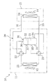
図2に示すように、圧縮・膨張ユニット(30)は、縦長で円筒形の密閉容器であるケーシング(31)の内部に、圧縮機構部(50)と、膨張機構部(60)と、モータ(40)とを収納したものである。また、圧縮・膨張ユニット(30)のケーシング(31)には、吸入ポート(34)、吐出ポート(35)、流入ポート(36)、及び流出ポート(37)が設けられている。
【0040】
上記ケーシング(31)の内部には、その高さ方向の中央部よりもやや上方にフレーム(67)が設けられている。このフレーム(67)により、ケーシング(31)の内部空間は、フレーム(67)の上側の上部空間(32)と、フレーム(67)の下側の下部空間(33)とに区画される。そして、ケーシング(31)内の上部空間(32)に膨張機構部(60)が設置され、その下部空間(33)に圧縮機構部(50)及びモータ(40)が設置されている。また、下部空間(33)において、モータ(40)は圧縮機構部(50)の上方に配置されている。
【0041】
上記モータ(40)は、ステータ(41)とロータ(42)とを備えている。ステータ(41)は、上記ケーシング(31)に固定されている。ロータ(42)は、ステータ(41)の内側に配置されている。また、ロータ(42)には、該ロータ(42)と同軸に駆動軸(45)が貫通している。この駆動軸(45)は、その下端部が圧縮機構部(50)に連結され、その上端部が膨張機構部(60)に連結されている。
【0042】
上記圧縮機構部(50)は、いわゆるスイング型ロータリ圧縮機に構成されている。該圧縮機構部(50)は、シリンダ(51)と、該シリンダ(51)のシリンダ室(52)に収納されたピストン(53)と、上記シリンダ室(52)の上面を閉鎖するフロントヘッド(54)と、上記シリンダ室(52)の下面を閉鎖するリアヘッド(55)とを備えている。そして、上記駆動軸(45)の下端部は、フロントヘッド(54)からシリンダ(51)を経てリアヘッド(55)に貫通している。
【0043】
上記ピストン(53)は、円環状に形成され、駆動軸(45)の下端部に回転自在に嵌め込まれている。ピストン(53)が嵌め込まれる駆動軸(45)の下端部は、下側偏心軸部(46)を構成している。この下側偏心軸部(46)は、駆動軸(45)の軸心より偏心して形成されている。
【0044】
上記ピストン(53)には、図示しないが、ブレードが一体に形成されている。該ブレードは、ブッシュを介してシリンダ(51)に挿入されている。そして、上記ピストン(53)はブッシュを支点に揺動し、シリンダ室(52)における容積を減少させて冷媒を圧縮する。
【0045】
上記シリンダ(51)には、冷媒の吸入口(57)が形成されている。この吸入口(57)には、吸入ポート(34)が接続されている。上記フロントヘッド(54)には、冷媒の吐出口(58)が形成されている。また、フロントヘッド(54)には、吐出口(58)を開閉する吐出弁(56)が設けられている。この吐出口(58)は、ケーシング(31)内の下部空間(33)に開口している。そして、下部空間(33)の上端付近には、吐出ポート(35)の一端が開口している。
【0046】
上記膨張機構部(60)は、スクロール型膨張機を構成している。この膨張機構部(60)は、固定スクロール(61)と可動スクロール(64)とを備えている。また、上記フレーム(67)は、ケーシング(31)内を上下に仕切るだけでなく、この膨張機構部(60)をも構成している。
【0047】
上記固定スクロール(61)は、鏡板(62)と、該鏡板(62)の下面側へ突出する渦巻き状の固定側ラップ(63)とを備えている。固定スクロール(61)の鏡板(62)は、ケーシング(31)に固定されている。一方、上記可動スクロール(64)は、板状の鏡板(65)と、該鏡板(62)の上面側へ突出する渦巻き状の固定側ラップ(63)とを備えている。そして、固定スクロール(61)と可動スクロール(64)とは互いに対向する姿勢で配置され、固定側ラップ(63)と可動側ラップ(66)が噛み合うことで膨張室(71,72)が区画される。固定側ラップ(63)及び可動側ラップ(66)の形状や、これらにより区画される膨張室(71,72)については、後述する。
【0048】
上記固定スクロール(61)の鏡板(62)の中央部には、冷媒の流入口(69)が形成されている。この流入口(69)は、膨張室(71,72)と上部空間(32)とを連通させるために、固定スクロール(61)の鏡板(62)を貫通して形成されている。また、流入口(69)は、所定の形状に形成されている。この点については後述する。ケーシング(31)の頂部には、上部空間(32)へ冷媒を導入するための流入ポート(36)が設けられている。固定側ラップ(63)及び可動側ラップ(66)の外周側には、冷媒の流出口(70)が形成されている。この流出口(70)には、流出ポート(37)が接続されている。
【0049】
上記可動スクロール(64)の鏡板(65)は、その下面側の中央部が下方に突出した形状となっており、この突出した部分が駆動軸(45)の上端部に回転自在に嵌め込まれている。この鏡板(65)が嵌め込まれる駆動軸(45)の上端部は、上側偏心軸部(47)を構成している。この上側偏心軸部(47)は、駆動軸(45)の軸心より偏心して形成されている。また、駆動軸(45)には、上側偏心軸部(47)の直下に鍔状の鍔部(48)が形成されている。可動スクロール(64)に作用するスラスト荷重は、駆動軸(45)の鍔部(48)とフレーム(67)とによって受けられる。
【0050】
更に、上記可動スクロール(64)は、オルダムリング(68)を介してフレーム(67)に支持されている。このオルダムリング(68)は、可動スクロール(64)の自転を規制するためのものである。そして、可動スクロール(64)は、自転することなく、所定の旋回半径で公転する。この可動スクロール(64)の旋回半径は、上側偏心軸部(47)の偏心量と同じである。
【0051】
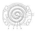
図3に示すように、可動側ラップ(66)は、円の伸開線であるインボリュート曲線を描くように形成されている。一方、固定側ラップ(63)は、可動側ラップ(66)の旋回運動に伴う軌跡の包絡線を描くように形成されている。また、固定側ラップ(63)は、その巻き角が可動側ラップ(66)の巻き角よりも約180°だけ大きくなるように形成されている。そして、このように形成された可動側ラップ(66)と固定側ラップ(63)は、互いの位相が概ね180°ずれた姿勢で噛み合わされている。
【0052】
尚、本実施形態1において、固定側ラップ(63)の最外周部分は周囲の壁と一体に形成されている。従って、図3においては、固定側ラップ(63)における最外周部分の内側面だけが現れているが、同図に二点鎖線で示すように、固定側ラップ(63)の最外周部分は可動側ラップ(66)の最外周部分の周囲を囲むように伸長されている。そして、固定側ラップ(63)は、その外周側端部が可動側ラップ(66)の外周側端部の直ぐ外側に位置するような形状とされている。つまり、固定側ラップ(63)における渦巻きの巻き終わり部が、可動側ラップ(66)における渦巻きの巻き終わり部の近傍に位置している。
【0053】
上述のように可動側ラップ(66)と固定側ラップ(63)を噛み合わせることにより、第1の膨張室である第1室(71)と第2の膨張室である第2室(72)とが対になって区画形成される。つまり、可動側ラップ(66)の外側面と固定側ラップ(63)の内側面とに挟まれて第1室(71)が形成され、固定側ラップ(63)の外側面と可動側ラップ(66)の内側面とに挟まれて第2室(72)が形成される。
【0054】
また、上述したように、本実施形態1では、固定側ラップ(63)の巻き角を可動側ラップ(66)の巻き角よりも大きくしている。そして、両者の巻き角を相違させることにより、対となる第1室(71)と第2室(72)とで冷媒の流出開始時期を相違させている。
【0055】
上述のように、冷媒の流入口(69)は、固定スクロール(61)の鏡板(62)の中央部に開口している。この流入口(69)は、固定側ラップ(63)における中心側端部の内側面に沿って開口している。また、流入口(69)の開口形状は、可動側ラップ(66)の中心側端部の移動方向に沿って円形を引き延ばしたような形状となっている。本実施形態1では、流入口(69)の開口形状を所定の形状とすることで、対となる第1室(71)と第2室(72)とで閉じ込み完了時期を相違させると共に、第1室(71)における膨張比と第2室(72)における膨張比とを一致させている。
【0056】
−運転動作−
上記空調機(10)の動作について説明する。ここでは、空調機(10)の冷房運転時及び暖房運転時の動作について説明し、続いて膨張機構部(60)の動作について説明する。
【0057】
《冷房運転》
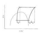
冷房運転時には、第1四路切換弁(21)及び第2四路切換弁(22)が図1に破線で示す状態に切り換えられる。この状態で圧縮・膨張ユニット(30)のモータ(40)に通電すると、冷媒回路(20)で冷媒が循環し、図4のモリエル線図(圧力−エンタルピ線図)に示すような冷凍サイクルが行われる。
【0058】
圧縮機構部(50)へは、図4における点aの状態の冷媒が吸入される。圧縮機構部(50)では、冷媒が点aの状態から点bの状態にまで圧縮される。尚、点bの状態における圧力は、冷媒である二酸化炭素(CO2)の臨界圧力よりも高くなっている。点bの状態となった冷媒は、ケーシング(31)内の下部空間(33)へ吐出され、吐出ポート(35)を通ってケーシング(31)の外部へ流出する。その後、この点bの状態の冷媒は、第1四路切換弁(21)を通って室外熱交換器(23)へ送られる。
【0059】
室外熱交換器(23)では、流入した冷媒が室外ファン(12)により送られる室外空気と熱交換する。この熱交換により、点bの状態の冷媒は、室外空気へ放熱して点cの状態となる。点cの状態の冷媒は、第2四路切換弁(22)を通過し、流入ポート(36)を通って圧縮・膨張ユニット(30)の上部空間(32)へ流入し、更には膨張機構部(60)へ流入する。
【0060】
膨張機構部(60)では、流入した冷媒が等エントロピ過程で膨張し、点cの状態から点dの状態へ変化する。ここで、冷媒を膨張弁で膨張させる場合には、図4に破線で示すように、冷媒が断熱膨張過程(等エンタルピ過程)で膨張する。これに対し、上記膨張機構部(60)では、冷媒が等エントロピ過程で膨張し、冷媒の圧力とエンタルピの両方が低下する。膨張機構部(60)から流出した点dの状態の冷媒は、流出ポート(37)を通って圧縮・膨張ユニット(30)から流出し、第2四路切換弁(22)を通過して室内熱交換器(24)へ送られる。
【0061】
室内熱交換器(24)では、流入した冷媒が室内ファン(14)により送られる室内空気と熱交換する。この熱交換により、点dの状態の冷媒が室内空気から吸熱して点aの状態となり、室内空気が冷却される。点aの状態の冷媒は、第1四路切換弁(21)を通過し、吸入ポート(34)を通って圧縮・膨張ユニット(30)の圧縮機構部(50)へ吸入される。そして、圧縮機構部(50)は、吸入した冷媒を再び圧縮して吐出し、この循環が繰り返される。
【0062】
ここで、膨張機構部(60)では、流入した冷媒を点cの状態から点dの状態にまで膨張させており、冷媒のエンタルピ低下量WEに相当する回転動力が回収される(図4参照)。この回収された回転動力は、駆動軸(45)によって圧縮機構部(50)へ伝達され、圧縮機構部(50)のピストン(53)を回転させるために利用される。そして、圧縮機構部(50)へはモータ(40)により回転動力WCが伝達され、膨張機構部(60)から伝達される回転動力WEと共にピストン(53)を回転駆動するために用いられる。
【0063】
《暖房運転》
暖房運転時には、第1四路切換弁(21)及び第2四路切換弁(22)が図1に実線で示す状態に切り換えられる。この状態で圧縮・膨張ユニット(30)のモータ(40)に通電すると、冷媒回路(20)で冷媒が循環して冷凍サイクルが行われる。
【0064】
具体的に、圧縮機構部(50)で圧縮された冷媒は、吐出ポート(35)を通って圧縮・膨張ユニット(30)から流出し、第1四路切換弁(21)を通過して室内熱交換器(24)へ送られる。室内熱交換器(24)では、流入した冷媒が室内空気と熱交換する。この熱交換により、冷媒が室内空気へ放熱し、室内空気が加熱される。室内熱交換器(24)で放熱した冷媒は、第2四路切換弁(22)を通過し、流入ポート(36)を通って膨張機構部(60)へ流入する。
【0065】
膨張機構部(60)では、流入した冷媒が等エントロピ過程で膨張する。膨張後の冷媒は、流出ポート(37)を通って圧縮・膨張ユニット(30)から流出し、第2四路切換弁(22)を通過して室外熱交換器(23)へ流入する。室外熱交換器(23)では、流入した冷媒が室外空気と熱交換を行い、冷媒が室外空気から吸熱する。吸熱後の冷媒は、第1四路切換弁(21)を通過し、吸入ポート(34)を通って圧縮・膨張ユニット(30)の圧縮機構部(50)へ吸入される。圧縮機構部(50)は、吸入した冷媒を再び圧縮して吐出し、この循環が繰り返される。
【0066】
《膨張機構部の動作》
膨張機構部(60)の動作について、図3及び図5を参照しながら説明する。
【0067】
図3において、固定側ラップ(63)及び可動側ラップ(66)の最内周部で区画される第1室(71)及び第2室(72)は、共に流入口(69)と連通している。この状態で、圧縮された後に放熱した高圧の冷媒は、流入口(69)を通って第1室(71)及び第2室(72)へ流入する。
【0068】
この状態から、可動スクロール(64)は、図3における時計方向に公転してゆく。そして、図5に示すように、可動スクロール(64)の回転角がT1となった時点で第2室(72)が流入口(69)から遮断され、第2室(72)の閉じ込みが完了する。その後、閉空間となった第2室(72)において冷媒が膨張し、可動スクロール(64)が回転するに従って第2室(72)の内圧が低下してゆく。この第2室(72)における内圧の低下は、可動スクロール(64)の回転角がT3となるまで続く。そして、可動スクロール(64)の回転角がT3となった時点で第2室(72)が流出口(70)と連通し、第2室(72)から流出口(70)へ冷媒が流出する。
【0069】
一方、第1室(71)は、可動スクロール(64)の回転角がT1となった時点において、依然として流入口(69)と連通している(図5参照)。そして、その後も第1室(71)へ冷媒が流入し続け、可動スクロール(64)の回転角がT2となった時点で第1室(71)の閉じ込みが完了する。その後、閉空間となった第1室(71)において冷媒が膨張し、可動スクロール(64)が回転するに従って第1室(71)の内圧が低下してゆく。この第1室(71)における内圧の低下は、可動スクロール(64)の回転角がT4となるまで続く。つまり、可動スクロール(64)の回転角がT3となって第2室(72)から冷媒が流出し始める時点においても、第1室(71)では依然として冷媒の膨張が継続している。そして、可動スクロール(64)の回転角がT4となった時点で第1室(71)が流出口(70)と連通し、第1室(71)から流出口(70)へ冷媒が流出する。
【0070】
このように、本実施形態1では、第1室(71)の閉じ込み完了時期が第2室(72)の閉じ込み完了時期よりも遅くなっており、更には、第1室(71)からの冷媒の流出開始時期が第2室(72)からの冷媒の流出開始時期よりも遅くなっている。このため、可動スクロール(64)の回転角がT1からT4に至るまでの何れの時点においても、第1室(71)の内圧の方が第2室(72)の内圧よりも高くなっている。また、第1室(71)の膨張比と第2室(72)の膨張比とは等しくなっており、図5に示すように、第1室(71)から流出する冷媒の圧力と第2室(72)から流出する冷媒の圧力とは同じ値となっている。
【0071】
−実施形態1の効果−
本実施形態1に係る膨張機構部(60)では、対となる第1室(71)と第2室(72)とについて、それぞれの閉じ込み完了時期と冷媒の流出開始時期とを相違させている。このため、本実施形態1によれば、第1室(71)及び第2室(72)における冷媒の膨張により可動スクロール(64)へ付与される回転力の変動幅を小さくでき、膨張機構部(60)において得られる回転動力のトルク変動幅を縮小できる。
【0072】
また、本実施形態1に係る膨張機構部(60)では、第1室(71)と第2室(72)とで閉じ込み完了時期がずれており、従来のような第1室(71)と第2室(72)が同時に閉じ込みを完了するものに比べ、流入口(69)を流れる冷媒の流速が低くなる。このため、流入口(69)を通過する際の冷媒の圧力損失を低減することができ、第1室(71)及び第2室(72)へ流入する流体の圧力を高く維持することができる。従って、本実施形態1によれば、膨張機構部(60)の出入口における冷媒の圧力差を充分に確保でき、膨張機構部(60)において取り出せる回転動力WEを増大させることができる。この結果、モータ(40)により圧縮機構部(50)へ付与すべき回転動力WCを削減して空調機(10)の消費電力を低減することができ、空調機(10)のCOPを向上させることができる。
【0073】
また、本実施形態1に係る膨張機構部(60)では、固定側ラップ(63)の外周側端部が可動側ラップ(66)の外周側端部の近傍に位置している。それ故、第1室(71)から流出する冷媒と第2室(72)から流出する冷媒とは、その何れもが流出後直ちに流出口(70)へ流れ込み、流出ポート(37)から圧縮・膨張ユニット(30)の外部へ送り出される。このため、従来のような第1室(71)と第2室(72)とで冷媒の流出地点が180°離れているものに比べ、流出した冷媒が流出口(70)に至るまでに流れる距離を短縮でき、その間における冷媒の吸熱量を削減できる。
【0074】
ここで、上記空調機(10)の冷房能力は、図4における点aと点dのエンタルピ差に冷媒循環量を乗じた値となる。一方、膨張機構部(60)から流出する冷媒のエンタルピが増大すると、点dが図4の右側へ移動することとなり、点aと点dのエンタルピ差が小さくなってしまう。これに対し、本実施形態1によれば、膨張機構部(60)から流出する冷媒のエンタルピが上昇するのを防止でき、これによって上記空調機(10)の冷房能力を充分に確保することができる。
【0075】
【発明の実施の形態2】
本発明の実施形態2は、上記実施形態1において、膨張機構部(60)の構成を変更したものである。ここでは、本実施形態2に係る膨張機構部(60)について、上記実施形態1と異なる点について説明する。
【0076】
図6に示すように、本実施形態2に係る膨張機構部(60)では、流入口(69)及び可動側ラップ(66)の形状が変更されている。具体的に、流入口(69)は、固定側ラップ(63)の中心側端部に沿って円形に開口している。一方、可動側ラップ(66)は、その中心側端部が上記実施形態1のものよりも短く形成されている。つまり、この可動側ラップ(66)の中心側端部は、上記実施形態1のものに比べ、インボリュート曲線の基礎円の中心から遠ざかっている。尚、本実施形態2に係る可動側ラップ(66)の外周側端部(渦巻きの巻き終わり部)の位置は、上記実施形態1のものと同じである。
【0077】
本実施形態2では、流入口(69)及び可動側ラップ(66)を上記の形状とすることで、第1室(71)と第2室(72)の閉じ込み完了時期をずらせると共に、第1室(71)と第2室(72)の膨張比を一致させている。つまり、上記実施形態1では、可動側ラップ(66)の中心側端部を固定側ラップ(63)の中心側端部と同一形状としつつ流入口(69)の開口形状によって第1室(71)と第2室(72)の閉じ込み完了時期を相違させているのに対し、本実施形態2では、流入口(69)の開口形状を単純な円形としながら可動側ラップ(66)の中心側端部の形状を変更することで第1室(71)と第2室(72)の閉じ込み完了時期を相違させている。
【0078】
【発明のその他の実施の形態】
上記の各実施形態では、本発明に係る冷凍装置を用いて空調機(10)を構成しているが、これに代えて温水を生成するための給湯機を構成してもよい。この場合、冷媒回路(20)では、室内熱交換器(24)に代えて冷媒と水を熱交換させる加熱用熱交換器が設けられ、更には第1四路切換弁(21)及び第2四路切換弁(22)が省略される。そして、圧縮機構部(50)から吐出された冷媒が加熱用熱交換器へ送られ、この冷媒からの放熱によって水が加熱される。また、放熱後の冷媒は、膨張機構部(60)で膨張した後に室外熱交換器(23)へ送られ、室外空気から吸熱した後に再び圧縮機構部(50)へ吸入される。
【0079】
また、上記の各実施形態では、圧縮機構部(50)において固定側ラップ(63)の長さを可動側ラップ(66)の長さよりも長くしているが、これとは逆に可動側ラップ(66)の長さを固定側ラップ(63)の長さの長さより長くしてもよい。この構成においても、第1室(71)と第2室(72)の閉じ込み完了時期及び冷媒の流出開始時期をずらせることは可能である。
【図面の簡単な説明】
【図1】 実施形態1に係る空調機の配管系統図である。
【図2】 実施形態1に係る圧縮・膨張ユニットの概略断面図である。
【図3】 実施形態1に係る固定側ラップと可動側ラップの形状を示す図2のA-A断面図である。
【図4】 実施形態1に係る空調機の冷凍サイクルを示すモリエル線図である。
【図5】 実施形態1に係る膨張機構部における可動スクロールの回転角と第1室及び第2室の内圧との関係図である。
【図6】 実施形態2に係る固定側ラップと可動側ラップの形状を示す図3相当図である。
【図7】 従来技術に係る固定側ラップと可動側ラップの形状を示す概略断面図である。
【図8】 従来技術に係るスクロール型流体機械における可動スクロールの回転角と流体室の内圧との関係図である。
【符号の説明】
(20) 冷媒回路
(50) 圧縮機構部(圧縮機)
(60) 膨張機構部(スクロール型膨張機)
(61) 固定スクロール
(64) 可動スクロール
(63) 固定側ラップ
(66) 可動側ラップ
(69) 流入口
(71) 第1室(第1の膨張室)
(72) 第2室(第2の膨張室)[0001]
BACKGROUND OF THE INVENTION
The present invention relates to a scroll type fluid machine, and particularly relates to a machine that rotates by expansion of a fluid.
[0002]
[Prior art]
Conventionally, scroll-type fluid machines are widely known and are used as compressors and expanders. For example, “New Edition Refrigeration and Air Conditioning Handbook 5th Edition Volume 2 Equipment” pages 37-43 published by the Japan Refrigeration Association discloses a scroll fluid machine applied to a refrigerant compressor. Japanese Patent Laid-Open No. 2001-107881 discloses a scroll type fluid machine that is applied to a refrigerant expander.
[0003]
As shown in FIG. 7, the scroll fluid machine includes a fixed scroll (a) and a movable scroll (b). The fixed scroll (a) and the movable scroll (b) are provided with the same shape and a spiral wrap (c). In this scroll type fluid machine, the wrap (c) of the fixed scroll (a) and the movable scroll (b) is meshed with the phase shifted by 180 °, and a fluid chamber (d) is paired between the wraps (c). Is formed.
[0004]
In the scroll fluid machine, the movable scroll (b) revolves around the center of the fixed scroll (a) with a constant turning radius. At that time, the movable scroll (b) revolves without rotating. The volume of the fluid chamber (d) partitioned by the fixed scroll (a) and the movable scroll (b) changes with the revolution of the movable scroll (b). Further, as shown in FIG. 8, the pressure of the fluid in the paired fluid chambers (d) changes in the same manner as the movable scroll (b) rotates. In the paired fluid chamber (d), the inflow of the fluid is completed at the same time as the movable scroll (b) rotates, and the outflow of the fluid is started at the same time.
[0005]
When the scroll type fluid machine is used as a compressor, the fluid is sucked into the fluid chamber (d) and compressed as the movable scroll (b) rotates, and is compressed from the center opening of the fixed scroll (a). The later fluid is discharged. On the other hand, when the scroll type fluid machine is used as an expander, fluid is introduced into the fluid chamber (d) from the opening at the center of the fixed scroll (a), and the movable scroll (d) is expanded by the expansion of the fluid in the fluid chamber (d). b) is driven to rotate.
[0006]
[Problems to be solved by the invention]
However, when the conventional scroll type fluid machine is used as an expander, there are the following problems.
[0007]
That is, in the conventional scroll type fluid machine, the pressure in the fluid chamber (d) that is paired varies in the same manner as the movable scroll (b) rotates (see FIG. 8), and acts on the movable scroll (b). The fluctuation of the rotational driving force increases. For this reason, there has been a problem that the torque fluctuation of the rotational power extracted from the scroll type fluid machine as the expander becomes large, and the compressor or the like cannot be smoothly driven by the obtained power.
[0008]
Further, since the fluid flows into the paired fluid chamber (d) at the same timing, the flow velocity at the inlet (e) for introducing the fluid into the fluid chamber (d) increases, and the pressure loss at the inlet (e) is reduced. It becomes excessive. As a result, there has been a problem that the pressure difference of the fluid at the entrance and exit of the scroll type fluid machine becomes small, and the power that can be taken out from the scroll type fluid machine as the expander decreases.
[0009]
The present invention has been made in view of the above points, and an object of the present invention is to reduce torque fluctuation of the obtained rotational power in a scroll type fluid machine used as an expander, and further to obtain the obtained rotational power. It is to improve.
[0010]
[Means for Solving the Problems]
The first solution provided by the present invention includes a fixed scroll (61) and a movable scroll (64) each having a spiral wrap (63, 66), and the fixed scroll (61) and the movable scroll. A scroll type in which the first expansion chamber (71) and the second expansion chamber (72) are formed in pairs by engaging the wraps (63, 66) of (64) with each other.ExpanderIs targeted. Then, the closing completion timing of the first expansion chamber (71) is delayed from the closing completion timing of the second expansion chamber (72), and the fluid from the first expansion chamber (71) The outflow start time is delayed from the fluid outflow start time from the second expansion chamber (72).
[0011]
AlsoThe first solving meansThenThe expansion ratio in the first expansion chamber (71) is equal to the expansion ratio in the second expansion chamber (72).The
[0012]
Also,the aboveFirstSolutionThenOne lap (63) of the fixed scroll (61) and the movable scroll (64) is extended to the vicinity of the outer peripheral end of the other wrap (66).The
[0013]
The present invention has takenSecondThe solution ofFirstIn the solution, in order to delay the closing completion timing of the first expansion chamber (71) from the closing completion timing of the second expansion chamber (72), the first expansion chamber (71) is opened to the fixed scroll (61) to expand the expansion chamber ( 71, 72) the inlet (69) for introducing the fluid into the predetermined shape.
[0014]
The present invention has takenThirdThe solution ofFirstIn the solution, in order to delay the closing completion timing of the first expansion chamber (71) from the closing completion timing of the second expansion chamber (72), the fixed scroll (61) or the movable scroll (64) The center side end of the wrap (63, 66) has a predetermined shape.
[0015]
The present invention has taken4thThe solution is intended for a refrigeration apparatus, and1st, 2nd or 3rdScroll typeExpander(60) is connected to a refrigerant compressor (50) and includes a refrigerant circuit (20) filled with carbon dioxide as a refrigerant, and the refrigerant circuit (20) circulates the refrigerant to perform a refrigeration cycle. The compressor (50) compresses the refrigerant up to a critical pressure of the refrigerant or higher and compresses the compressed refrigerant into the scroll type.ExpanderThe power recovered by expansion in (60) is used to drive the compressor (50).
[0016]
-Action-
In the first solving means, while the movable scroll (64) rotates, the first expansion chamber (71) becomes a sealed space and the second expansion chamber (72) becomes a sealed space. The period is different. This point will be described.
[0017]
First,FirstIn the solution, the first expansion chamber (71) and the second expansion chamber (72) have different timings for completing the closing. That is, even after the inflow of the fluid into the second expansion chamber (72) is completed, the fluid continues to flow into the first expansion chamber (71). Then, after the movable scroll (64) revolves by a predetermined angle from the completion of the closing of the second expansion chamber (72), the closing of the first expansion chamber (71) is completed. Thereafter, the fluid expands in each expansion chamber (71, 72), and the expansion work of the fluid is taken out as the rotational power of the movable scroll (64). At that time, since the closing timings of the expansion chambers (71, 72) are different, the internal pressures of the expansion chambers (71, 72) at a certain moment are different from each other.
[0018]
Furthermore,FirstIn the solving means, the timing at which the fluid starts to flow out of the expansion chambers (71, 72) is different between the first expansion chamber (71) and the second expansion chamber (72). That is, even after the fluid starts to flow out of the second expansion chamber (72), the fluid continues to expand in the first expansion chamber (71). Then, after the movable scroll (64) revolves by a predetermined angle from the time when the fluid starts to flow out of the second expansion chamber (72), the fluid starts to flow out of the first expansion chamber (71).
[0019]
The firstIn this solution, the expansion ratios of the paired expansion chambers (71, 72) are equal to each other. That is, the pressure of the fluid flowing out from the expansion chambers (71, 72) is the same in any of the paired expansion chambers (71, 72). Here, the expansion ratio is a ratio of the volume of the expansion chamber (71, 72) immediately after completion of the confinement to the volume of the expansion chamber (71, 72) immediately before the start of fluid outflow.
[0020]
The firstIn the solution, the wrap (63) of the fixed scroll (61) and the wrap (66) of the movable scroll (64) are engaged with each other, and one outer peripheral end is the other outer peripheral end. It is formed in a predetermined shape so as to be located in the vicinity of. The fluid flowing out from the first or second expansion chamber (71, 72) is sent out of the expansion chamber (71, 72) from the vicinity of the outer peripheral side end of each lap (63, 66). That is, the fluid in both expansion chambers (71, 72) flows out from the expansion chambers (71, 72) at substantially the same position in the circumferential direction of the wraps (63, 66).
[0021]
the aboveSecondIn the solution, the fluid inflow port (69) is formed in a predetermined shape, thereby shifting the closing completion timing of the first expansion chamber (71) and the second expansion chamber (72). That is, the fluid inflow port (69) has a shape that makes the completion timings of closing of the two expansion chambers (71, 72) different.
[0022]
the aboveThirdIn this solution, the end of the first expansion chamber (71) and the second expansion chamber (72) can be closed by shifting the center end of the wrap (63, 66) to a predetermined shape. Yes. That is, the center side end portion of the wrap (63, 66) is shaped so that the closing completion timings of the two expansion chambers (71, 72) are different. The wraps (63, 66) having a predetermined shape may be formed on the fixed scroll (61) or may be formed on the movable scroll (64).
[0023]
the above4thIn the solution, the scroll type according to the present inventionExpanderA refrigeration apparatus (10) using (60) is configured. In this refrigeration system (10), scroll typeExpander(60) is connected to the refrigerant circuit (20) together with the refrigerant compressor (50). In the refrigerant circuit (20), carbon dioxide (CO2) Is filled.
[0024]
In the refrigerant circuit (20), carbon dioxide as a refrigerant circulates and a refrigeration cycle is performed. Specifically, the compressor (50) compresses the refrigerant, and the refrigerant (CO2) To a pressure higher than the critical pressure. The refrigerant discharged from the compressor (50) radiates heat to, for example, air. The refrigerant after heat dissipation is the scroll type as an expander.ExpanderFlows into (60). Scroll typeExpanderIn (60), the expansion work of the refrigerant is taken out as rotational power. Scroll typeExpanderThe rotational power extracted in (60) is used as power for driving the compressor (50) to compress the refrigerant. Scroll typeExpanderThe expanded refrigerant that has flowed out of (60) absorbs heat from, for example, air, and is then sucked into the compressor (50) and compressed again.
[0025]
【The invention's effect】
In the present invention, the first expansion chamber (71) and the second expansion chamber (72) formed as a pair have different closing completion timings and fluid outflow start timings. Therefore, according to the present invention, the fluctuation range of the rotational force applied to the movable scroll (64) due to the expansion of the fluid in the expansion chambers (71, 72) can be reduced, and the scroll type as an expanderExpanderThe torque fluctuation range of the rotational power obtained in (60) can be reduced.
[0026]
Further, in the present invention, the closing completion time is shifted between the first expansion chamber (71) and the second expansion chamber (72), and both the conventional expansion chambers (71, 72) are simultaneously closed. The flow rate of the fluid through the fluid inlet (69) is lower than that of completing the above. For this reason, the pressure loss of the fluid at the time of passing through the inflow port (69) can be reduced, and the pressure of the fluid flowing into the expansion chambers (71, 72) can be maintained high. Thus, according to the present invention, SuCrawl typeExpander(60) A sufficient pressure difference between the fluid flowing into and out of the fluid can be secured.ExpanderThe rotational power that can be extracted with (60) can be improved.
[0027]
Also,The present inventionThen, the expansion ratios in the paired expansion chambers (71, 72) are equal to each other. Therefore, the movable scroll (64) can be rotated smoothly, and the scroll typeExpanderThe torque fluctuation range of the rotational power extracted from (60) can be further reduced.
[0028]
Also,The present inventionThen, the wraps (63, 66) of the fixed scroll (61) or the movable scroll (64) have a predetermined shape. For this reason, the fluid in the expansion chamber (71, 72) can flow out from substantially the same position in the circumferential direction of the wrap (63, 66).
[0029]
Here, when the conventional scroll type fluid machine shown in FIG. 7 is used as an expander, the fluid in the expansion chamber (d) flows out from a position 180 ° apart in the circumferential direction of the wrap (c). Therefore, if only one fluid outflow port from the scroll fluid machine is to be used, the fluid flowing out from one of the expansion chambers (d) flows around the outside of the wrap (c) and flows out. It will be led to the port. And while detouring outside the wrap (c), the fluid flowing out from the expansion chamber (d) absorbs heat, and the enthalpy of the fluid sent out from the scroll type fluid machine increases.
[0030]
In contrast,The present inventionAccordingly, the fluid in the expansion chamber (71, 72) can flow out from substantially the same position in the circumferential direction of the wrap (63, 66). Therefore, the fluid flowing out from the expansion chamber (71, 72) can be immediately guided to one outlet port (37), and the scroll typeExpanderAn increase in the enthalpy of the fluid delivered from (60) can be prevented.
[0031]
Also, above4thIn the solution, the scroll type according to the present inventionExpander(60) is provided as an expander in the refrigeration apparatus (10), the expansion work of the refrigerant is recovered as rotational power, and the recovered rotational power is used to drive the compressor (50). Therefore, according to this solution, energy such as electric power supplied from the outside in order to compress the refrigerant by the compressor (50) can be reduced, and the COP (coefficient of performance) of the refrigeration apparatus (10) can be improved. it can.
[0032]
Furthermore, the present inventionScroll typeExpander(60)Of the fourth solution providedRefrigeration equipment (10)ThenThe following effects can be obtained. In other words, when the object is cooled by this refrigeration system (10), SuCrawl typeExpanderThe expanded refrigerant that has flowed out of (60) absorbs heat from the object to be cooled, such as air. on the other hand,The present inventionScroll typeExpanderAccording to (60), by making the wrap (63,66) a predetermined shape, SuCrawl typeExpanderIt is possible to keep the enthalpy of the refrigerant flowing out from (60) low. Therefore, in this case, the amount of heat that the expanded refrigerant can absorb from the object can be increased, and the cooling capacity of the refrigeration apparatus (10) can be improved.
[0033]
DESCRIPTION OF THE PREFERRED EMBODIMENTS Embodiment 1
Hereinafter, embodiments of the present invention will be described in detail with reference to the drawings. The first embodiment is an air conditioner (10) configured by a refrigeration apparatus according to the present invention.
[0034]
<Overall configuration of air conditioner>
As shown in FIG. 1, the air conditioner (10) is a so-called separate type, and includes an outdoor unit (11) and an indoor unit (13). The outdoor unit (11) includes an outdoor fan (12), an outdoor heat exchanger (23), a first four-way switching valve (21), a second four-way switching valve (22), and a compression / expansion unit (30). Is stored. The indoor unit (13) houses an indoor fan (14) and an indoor heat exchanger (24). The outdoor unit (11) is installed outdoors, and the indoor unit (13) is installed indoors. The outdoor unit (11) and the indoor unit (13) are connected by a pair of connecting pipes (15, 16). Details of the compression / expansion unit (30) will be described later.
[0035]
The air conditioner (10) is provided with a refrigerant circuit (20). The refrigerant circuit (20) is a closed circuit to which a compression / expansion unit (30), an indoor heat exchanger (24), and the like are connected. The refrigerant circuit (20) includes carbon dioxide (CO) as a refrigerant.2) Is filled.
[0036]
Both the outdoor heat exchanger (23) and the indoor heat exchanger (24) are cross fin type fin-and-tube heat exchangers. In the outdoor heat exchanger (23), the refrigerant circulating in the refrigerant circuit (20) exchanges heat with outdoor air. In the indoor heat exchanger (24), the refrigerant circulating in the refrigerant circuit (20) exchanges heat with room air.
[0037]
The first four-way selector valve (21) has four ports. The first four-way switching valve (21) has a first port connected to the discharge port (35) of the compression / expansion unit (30) and a second port connected to the interior via the connection pipe (15). One end of the heat exchanger (24) is piped, the third port is piped to one end of the outdoor heat exchanger (23), and the fourth port is the suction port (34) of the compression / expansion unit (30) And piping connected. The first four-way switching valve (21) is in a state where the first port and the second port communicate with each other and the third port and the fourth port communicate with each other (a state indicated by a solid line in FIG. 1). Then, the first port and the third port communicate with each other and the second port and the fourth port communicate with each other (state indicated by a broken line in FIG. 1).
[0038]
The second four-way selector valve (22) has four ports. The second four-way selector valve (22) has a first port connected to the outflow port (37) of the compression / expansion unit (30) and a second port other than the outdoor heat exchanger (23). The third port is connected to the other end of the indoor heat exchanger (24) via the connecting pipe (16), and the fourth port is connected to the compression / expansion unit (30).Inflow port (36)And piping connected. AndSecond four-way selector valve (22)The first port and the second port communicate with each other and the third port and the fourth port communicate with each other (shown by a solid line in FIG. 1), and the first port and the third port. And the second port and the fourth port communicate with each other (a state indicated by a broken line in FIG. 1).
[0039]
<Configuration of compression / expansion unit>
As shown in FIG. 2, the compression / expansion unit (30) includes a compression mechanism part (50), an expansion mechanism part (60), a motor inside a casing (31) that is a vertically long and cylindrical sealed container. (40) is stored. The casing (31) of the compression / expansion unit (30) is provided with a suction port (34), a discharge port (35), an inflow port (36), and an outflow port (37).
[0040]
Inside the casing (31), a frame (67) is provided slightly above the center in the height direction. The frame (67) divides the internal space of the casing (31) into an upper space (32) above the frame (67) and a lower space (33) below the frame (67). And the expansion mechanism part (60) is installed in the upper space (32) in a casing (31), and the compression mechanism part (50) and the motor (40) are installed in the lower space (33). In the lower space (33), the motor (40) is disposed above the compression mechanism (50).
[0041]
The motor (40) includes a stator (41) and a rotor (42). The stator (41) is fixed to the casing (31). The rotor (42) is disposed inside the stator (41). Further, the drive shaft (45) passes through the rotor (42) coaxially with the rotor (42). The drive shaft (45) has a lower end connected to the compression mechanism (50) and an upper end connected to the expansion mechanism (60).
[0042]
The compression mechanism section (50) is configured as a so-called swing type rotary compressor. The compression mechanism (50) includes a cylinder (51), a piston (53) housed in a cylinder chamber (52) of the cylinder (51), and a front head ( 54) and a rear head (55) for closing the lower surface of the cylinder chamber (52). And the lower end part of the said drive shaft (45) has penetrated the rear head (55) through the cylinder (51) from the front head (54).
[0043]
The piston (53) is formed in an annular shape and is rotatably fitted to the lower end portion of the drive shaft (45). The lower end portion of the drive shaft (45) into which the piston (53) is fitted constitutes the lower eccentric shaft portion (46). The lower eccentric shaft portion (46) is formed eccentric from the shaft center of the drive shaft (45).
[0044]
Although not shown, the piston (53) is integrally formed with a blade. The blade is inserted into the cylinder (51) via a bush. The piston (53) swings about the bush as a fulcrum, and reduces the volume in the cylinder chamber (52) to compress the refrigerant.
[0045]
The cylinder (51) is formed with a refrigerant suction port (57). The suction port (34) is connected to the suction port (57). The front head (54) is formed with a refrigerant outlet (58). The front head (54) is provided with a discharge valve (56) for opening and closing the discharge port (58). The discharge port (58) opens to the lower space (33) in the casing (31). One end of the discharge port (35) is open near the upper end of the lower space (33).
[0046]
The expansion mechanism (60) is a scroll typeExpanderIs configured. The expansion mechanism (60) includes a fixed scroll (61) and a movable scroll (64). The frame (67) not only partitions the casing (31) up and down but also constitutes the expansion mechanism (60).
[0047]
The fixed scroll (61) includes an end plate (62) and a spiral fixed side wrap (63) protruding toward the lower surface side of the end plate (62). The end plate (62) of the fixed scroll (61) is fixed to the casing (31). On the other hand, the movable scroll (64) includes a plate-shaped end plate (65) and a spiral fixed-side wrap (63) protruding toward the upper surface side of the end plate (62). The fixed scroll (61) and the movable scroll (64) are arranged so as to face each other, and the expansion chamber (71, 72) is defined by the fixed side wrap (63) and the movable side wrap (66) meshing with each other. The The shapes of the fixed wrap (63) and the movable wrap (66) and the expansion chambers (71, 72) defined by these will be described later.
[0048]
A refrigerant inlet (69) is formed at the center of the end plate (62) of the fixed scroll (61). The inflow port (69) is formed through the end plate (62) of the fixed scroll (61) in order to allow the expansion chambers (71, 72) and the upper space (32) to communicate with each other. The inflow port (69) is formed in a predetermined shape. This point will be described later. An inlet port (36) for introducing the refrigerant into the upper space (32) is provided at the top of the casing (31). A refrigerant outlet (70) is formed on the outer peripheral side of the fixed wrap (63) and the movable wrap (66). The outflow port (37) is connected to the outflow port (70).
[0049]
The end plate (65) of the movable scroll (64) has a shape in which the central portion on the lower surface protrudes downward, and the protruding portion is rotatably fitted to the upper end of the drive shaft (45). Yes. The upper end portion of the drive shaft (45) into which the end plate (65) is fitted constitutes the upper eccentric shaft portion (47). The upper eccentric shaft portion (47) is formed eccentric from the axis of the drive shaft (45). The drive shaft (45) is formed with a bowl-shaped flange (48) immediately below the upper eccentric shaft (47). The thrust load acting on the movable scroll (64) is received by the flange portion (48) and the frame (67) of the drive shaft (45).
[0050]
Further, the movable scroll (64) is supported by the frame (67) via an Oldham ring (68). The Oldham ring (68) is for regulating the rotation of the movable scroll (64). The movable scroll (64) revolves at a predetermined turning radius without rotating. The turning radius of the movable scroll (64) is the same as the eccentric amount of the upper eccentric shaft portion (47).
[0051]
As shown in FIG. 3, the movable side wrap (66) is formed so as to draw an involute curve which is a circle extension line. On the other hand, the fixed side wrap (63) is formed so as to draw an envelope of a trajectory accompanying the turning motion of the movable side wrap (66). Further, the fixed side wrap (63) is formed so that the winding angle is larger by about 180 ° than the winding angle of the movable side wrap (66). The movable side wrap (66) and the fixed side wrap (63) formed in this way are meshed with each other in a posture in which the phases thereof are shifted by approximately 180 °.
[0052]
In the first embodiment, the outermost peripheral portion of the fixed side wrap (63) is formed integrally with the surrounding wall. Therefore, in FIG. 3, only the inner surface of the outermost peripheral portion of the fixed side wrap (63) appears, but the outermost peripheral portion of the fixed side wrap (63) is movable as shown by a two-dot chain line in the same figure. The side wrap (66) is extended so as to surround the outermost peripheral portion. And the fixed side wrap (63) is made into the shape where the outer peripheral side edge part is located just outside the outer peripheral side edge part of a movable side wrap (66). That is, the spiral end of the fixed wrap (63) is positioned in the vicinity of the spiral end of the movable wrap (66).
[0053]
By engaging the movable side wrap (66) and the fixed side wrap (63) as described above, the first chamber (71) which is the first expansion chamber and the second chamber (72) which is the second expansion chamber. And are paired to form a compartment. That is, the first chamber (71) is formed between the outer surface of the movable wrap (66) and the inner surface of the fixed wrap (63), and the outer surface of the fixed wrap (63) and the movable wrap ( 66) and the second chamber (72) is formed.
[0054]
Further, as described above, in the first embodiment, the winding angle of the fixed side wrap (63) is made larger than the winding angle of the movable side wrap (66). And the outflow start time of a refrigerant | coolant is made different in the 1st chamber (71) and 2nd chamber (72) which become a pair by making both winding angles differ.
[0055]
As described above, the refrigerant inlet (69) opens at the center of the end plate (62) of the fixed scroll (61). This inflow port (69) is opened along the inner surface of the center side end portion of the fixed side wrap (63). Moreover, the opening shape of the inflow port (69) is a shape in which a circle is extended along the moving direction of the center side end of the movable side wrap (66). In Embodiment 1, by making the opening shape of the inflow port (69) a predetermined shape, the first chamber (71) and the second chamber (72) as a pair have different closing completion timings, The expansion ratio in the first chamber (71) is matched with the expansion ratio in the second chamber (72).
[0056]
-Driving action-
The operation of the air conditioner (10) will be described. Here, the operation during the cooling operation and the heating operation of the air conditioner (10) will be described, and then the operation of the expansion mechanism section (60) will be described.
[0057]
《Cooling operation》
During the cooling operation, the first four-way switching valve (21) and the second four-way switching valve (22) are switched to the state indicated by the broken line in FIG. When the motor (40) of the compression / expansion unit (30) is energized in this state, the refrigerant circulates in the refrigerant circuit (20), and a refrigeration cycle as shown in the Mollier diagram (pressure-enthalpy diagram) in FIG. Done.
[0058]
The refrigerant at the point a in FIG. 4 is sucked into the compression mechanism section (50). In the compression mechanism section (50), the refrigerant is compressed from the point a state to the point b state. Note that the pressure in the state of the point b is carbon dioxide (CO2) Is higher than the critical pressure. The refrigerant in the state of point b is discharged into the lower space (33) in the casing (31) and flows out of the casing (31) through the discharge port (35). Thereafter, the refrigerant in the state of this point b is sent to the outdoor heat exchanger (23) through the first four-way switching valve (21).
[0059]
In the outdoor heat exchanger (23), the refrigerant flowing in exchanges heat with outdoor air sent by the outdoor fan (12). By this heat exchange, the refrigerant in the point b state dissipates heat to the outdoor air and enters the point c state. The refrigerant in the state of point c passes through the second four-way switching valve (22), flows into the upper space (32) of the compression / expansion unit (30) through the inflow port (36), and further expands. Flows into section (60).
[0060]
In the expansion mechanism section (60), the refrigerant that has flowed in expands in the isentropic process, and changes from the state at point c to the state at point d. Here, when the refrigerant is expanded by the expansion valve, the refrigerant expands in an adiabatic expansion process (equal enthalpy process) as shown by a broken line in FIG. On the other hand, in the expansion mechanism section (60), the refrigerant expands in the isentropic process, and both the pressure and enthalpy of the refrigerant decrease. The refrigerant in the state of point d flowing out from the expansion mechanism section (60) flows out from the compression / expansion unit (30) through the outflow port (37), passes through the second four-way switching valve (22), and passes through the room. It is sent to the heat exchanger (24).
[0061]
In the indoor heat exchanger (24), the refrigerant flowing in exchanges heat with the indoor air sent by the indoor fan (14). By this heat exchange, the refrigerant in the state of the point d absorbs heat from the room air to be in the state of the point a, and the room air is cooled. The refrigerant in the state of point a passes through the first four-way selector valve (21), and is sucked into the compression mechanism (50) of the compression / expansion unit (30) through the suction port (34). Then, the compression mechanism section (50) compresses and discharges the sucked refrigerant again, and this circulation is repeated.
[0062]
Here, in the expansion mechanism section (60), the refrigerant that has flowed in is expanded from the state of the point c to the state of the point d, and the enthalpy reduction amount W of the refrigerantEIs recovered (see FIG. 4). The recovered rotational power is transmitted to the compression mechanism section (50) by the drive shaft (45) and used to rotate the piston (53) of the compression mechanism section (50). The compression mechanism (50) is rotated by a motor (40) with rotational power W.CIs transmitted and rotational power W is transmitted from the expansion mechanism (60).EAt the same time, it is used for rotationally driving the piston (53).
[0063]
《Heating operation》
During the heating operation, the first four-way switching valve (21) and the second four-way switching valve (22) are switched to the state shown by the solid line in FIG. When the motor (40) of the compression / expansion unit (30) is energized in this state, the refrigerant circulates in the refrigerant circuit (20) to perform a refrigeration cycle.
[0064]
Specifically, the refrigerant compressed by the compression mechanism (50) flows out from the compression / expansion unit (30) through the discharge port (35), passes through the first four-way switching valve (21), and passes through the room. It is sent to the heat exchanger (24). In the indoor heat exchanger (24), the refrigerant flowing in exchanges heat with room air. By this heat exchange, the refrigerant dissipates heat to the room air, and the room air is heated. The refrigerant radiated by the indoor heat exchanger (24) passes through the second four-way switching valve (22) and flows into the expansion mechanism section (60) through the inflow port (36).
[0065]
In the expansion mechanism section (60), the refrigerant that has flowed in expands in the isentropic process. The expanded refrigerant flows out from the compression / expansion unit (30) through the outflow port (37), passes through the second four-way switching valve (22), and flows into the outdoor heat exchanger (23). In the outdoor heat exchanger (23), the refrigerant that has flowed in exchanges heat with the outdoor air, and the refrigerant absorbs heat from the outdoor air. The refrigerant after the heat absorption passes through the first four-way switching valve (21), and is sucked into the compression mechanism (50) of the compression / expansion unit (30) through the suction port (34). The compression mechanism (50) compresses and discharges the sucked refrigerant again, and this circulation is repeated.
[0066]
<Operation of expansion mechanism>
The operation of the expansion mechanism section (60) will be described with reference to FIGS.
[0067]
In FIG. 3, the first chamber (71) and the second chamber (72) defined by the innermost peripheral portions of the fixed side wrap (63) and the movable side wrap (66) both communicate with the inflow port (69). ing. In this state, the high-pressure refrigerant that has released heat after being compressed flows into the first chamber (71) and the second chamber (72) through the inlet (69).
[0068]
From this state, the movable scroll (64) revolves clockwise in FIG. As shown in FIG. 5, the rotation angle of the movable scroll (64) is T1At this point, the second chamber (72) is shut off from the inlet (69), and the second chamber (72) is completely closed. Thereafter, the refrigerant expands in the second chamber (72) that has become a closed space, and the internal pressure of the second chamber (72) decreases as the movable scroll (64) rotates. The decrease in internal pressure in the second chamber (72) is caused by the rotational angle of the movable scroll (64) being T.3Continue until The rotation angle of the movable scroll (64) is T3At this point, the second chamber (72) communicates with the outlet (70), and the refrigerant flows out from the second chamber (72) to the outlet (70).
[0069]
On the other hand, in the first chamber (71), the rotation angle of the movable scroll (64) is T.1At that time, it still communicates with the inlet (69) (see FIG. 5). Thereafter, the refrigerant continues to flow into the first chamber (71), and the rotation angle of the movable scroll (64) is T2At this point, the closing of the first chamber (71) is completed. Thereafter, the refrigerant expands in the closed first chamber (71), and the internal pressure of the first chamber (71) decreases as the movable scroll (64) rotates. The decrease in internal pressure in the first chamber (71) is caused by the rotational angle of the movable scroll (64) being T.4Continue until That is, the rotation angle of the movable scroll (64) is T3Thus, even when the refrigerant begins to flow out of the second chamber (72), the expansion of the refrigerant continues in the first chamber (71). The rotation angle of the movable scroll (64) is T4At this point, the first chamber (71) communicates with the outlet (70), and the refrigerant flows out from the first chamber (71) to the outlet (70).
[0070]
Thus, in the first embodiment, the closing completion timing of the first chamber (71) is later than the closing completion timing of the second chamber (72), and further from the first chamber (71). The refrigerant outflow start timing is later than the refrigerant outflow start timing from the second chamber (72). Therefore, the rotation angle of the movable scroll (64) is T1To T4At any time up to the point, the internal pressure of the first chamber (71) is higher than the internal pressure of the second chamber (72). Further, the expansion ratio of the first chamber (71) and the expansion ratio of the second chamber (72) are equal, and as shown in FIG. 5, the pressure of the refrigerant flowing out of the first chamber (71) and the second The pressure of the refrigerant flowing out of the chamber (72) is the same value.
[0071]
-Effect of Embodiment 1-
In the expansion mechanism section (60) according to the first embodiment, for each of the first chamber (71) and the second chamber (72) as a pair, the closing completion timing and the refrigerant outflow start timing are different. Yes. Therefore, according to the first embodiment, the fluctuation range of the rotational force applied to the movable scroll (64) due to the expansion of the refrigerant in the first chamber (71) and the second chamber (72) can be reduced, and the expansion mechanism section The torque fluctuation range of the rotational power obtained in (60) can be reduced.
[0072]
Further, in the expansion mechanism section (60) according to the first embodiment, the closing completion time is shifted between the first chamber (71) and the second chamber (72), and the first chamber (71) as in the conventional case is shifted. And the flow rate of the refrigerant flowing through the inflow port (69) is lower than that in which the second chamber (72) is closed at the same time. For this reason, the pressure loss of the refrigerant | coolant at the time of passing an inflow port (69) can be reduced, and the pressure of the fluid which flows in into a 1st chamber (71) and a 2nd chamber (72) can be maintained high. . Therefore, according to the first embodiment, the refrigerant pressure difference at the inlet / outlet of the expansion mechanism section (60) can be sufficiently secured, and the rotational power W that can be taken out by the expansion mechanism section (60).ECan be increased. As a result, the rotational power W to be applied to the compression mechanism section (50) by the motor (40).CThe power consumption of the air conditioner (10) can be reduced, and the COP of the air conditioner (10) can be improved.
[0073]
Moreover, in the expansion mechanism part (60) according to the first embodiment, the outer peripheral side end of the fixed side wrap (63) is located in the vicinity of the outer peripheral side end of the movable side wrap (66). Therefore, both the refrigerant flowing out from the first chamber (71) and the refrigerant flowing out from the second chamber (72) flow into the outlet (70) immediately after flowing out, and are compressed and discharged from the outlet port (37). It is sent out of the expansion unit (30). For this reason, compared with the conventional one where the outflow point of the refrigerant is 180 ° apart between the first chamber (71) and the second chamber (72), the outflowed refrigerant flows until reaching the outlet (70). The distance can be shortened, and the heat absorption amount of the refrigerant in the meantime can be reduced.
[0074]
Here, the cooling capacity of the air conditioner (10) is a value obtained by multiplying the enthalpy difference between the points a and d in FIG. 4 by the refrigerant circulation amount. On the other hand, when the enthalpy of the refrigerant flowing out from the expansion mechanism section (60) increases, the point d moves to the right side of FIG. 4, and the enthalpy difference between the points a and d decreases. On the other hand, according to the first embodiment, it is possible to prevent the enthalpy of the refrigerant flowing out from the expansion mechanism part (60) from rising, and thereby to sufficiently secure the cooling capacity of the air conditioner (10). it can.
[0075]
Second Embodiment of the Invention
The second embodiment of the present invention is obtained by changing the configuration of the expansion mechanism section (60) in the first embodiment. Here, the difference between the expansion mechanism section (60) according to the second embodiment and the first embodiment will be described.
[0076]
As shown in FIG. 6, in the expansion mechanism part (60) according to the second embodiment, the shapes of the inflow port (69) and the movable side wrap (66) are changed. Specifically, the inflow port (69) opens in a circular shape along the center side end of the fixed side wrap (63). On the other hand, the movable side wrap (66) has a center side end portion shorter than that of the first embodiment. That is, the center side end portion of the movable wrap (66) is further away from the center of the base circle of the involute curve than that of the first embodiment. In addition, the position of the outer peripheral side end part (vortex end part) of the movable side wrap (66) according to the second embodiment is the same as that of the first embodiment.
[0077]
In Embodiment 2, by making the inflow port (69) and the movable side wrap (66) as described above, the timing for completing the closing of the first chamber (71) and the second chamber (72) is shifted, The expansion ratios of the first chamber (71) and the second chamber (72) are matched. That is, in the first embodiment, the first chamber (71) is formed by the shape of the opening of the inflow port (69) while making the center side end of the movable side wrap (66) the same shape as the center side end of the fixed side wrap (63). ) And the second chamber (72) are closed at different timings. In the second embodiment, the center of the movable wrap (66) is made while the opening shape of the inlet (69) is a simple circle. The closing completion timing of the first chamber (71) and the second chamber (72) is made different by changing the shape of the side end portion.
[0078]
Other Embodiments of the Invention
In each of the above embodiments, the air conditioner (10) is configured using the refrigeration apparatus according to the present invention, but a hot water supply device for generating hot water may be configured instead. In this case, in the refrigerant circuit (20), a heating heat exchanger for exchanging heat between the refrigerant and water is provided instead of the indoor heat exchanger (24), and further, the first four-way switching valve (21) and the second The four-way switching valve (22) is omitted. And the refrigerant | coolant discharged from the compression mechanism part (50) is sent to the heat exchanger for a heating, and water is heated by the thermal radiation from this refrigerant | coolant. The refrigerant after heat dissipation is expanded by the expansion mechanism section (60) and then sent to the outdoor heat exchanger (23). After absorbing heat from the outdoor air, the refrigerant is again sucked into the compression mechanism section (50).
[0079]
Further, in each of the above embodiments, the length of the fixed side wrap (63) is longer than the length of the movable side wrap (66) in the compression mechanism (50). The length of (66) may be longer than the length of the fixed side wrap (63). Even in this configuration, it is possible to shift the closing completion timing of the first chamber (71) and the second chamber (72) and the refrigerant start-up timing.
[Brief description of the drawings]
FIG. 1 is a piping system diagram of an air conditioner according to a first embodiment.
FIG. 2 is a schematic sectional view of the compression / expansion unit according to the first embodiment.
3 is a cross-sectional view taken along the line AA of FIG. 2 showing the shapes of a fixed wrap and a movable wrap according to Embodiment 1.
4 is a Mollier diagram showing a refrigeration cycle of the air conditioner according to Embodiment 1. FIG.
FIG. 5 is a relationship diagram between the rotation angle of the movable scroll and the internal pressures of the first chamber and the second chamber in the expansion mechanism section according to the first embodiment.
6 is a view corresponding to FIG. 3 and showing shapes of a fixed side wrap and a movable side wrap according to Embodiment 2. FIG.
FIG. 7 is a schematic cross-sectional view showing shapes of a fixed side wrap and a movable side wrap according to the prior art.
FIG. 8 is a relationship diagram between the rotation angle of the movable scroll and the internal pressure of the fluid chamber in the scroll type fluid machine according to the prior art.
[Explanation of symbols]
(20) Refrigerant circuit
(50) Compression mechanism (compressor)
(60) Expansion mechanism (scroll typeExpander)
(61) Fixed scroll
(64) Movable scroll
(63) Fixed wrap
(66) Movable wrap
(69) Inlet
(71) First chamber (first expansion chamber)
(72) Second chamber (second expansion chamber)
Claims (4)
上記第1の膨張室(71)の閉じ込み完了時期が上記第2の膨張室(72)の閉じ込み完了時期よりも遅らされ、且つ上記第1の膨張室(71)からの流体の流出開始時期が上記第2の膨張室(72)からの流体の流出開始時期よりも遅らされる一方、
上記第1の膨張室(71)における膨張比と上記第2の膨張室(72)における膨張比とが等しくなるように構成され、
上記固定スクロール(61)と上記可動スクロール(64)のうち何れか一方のラップ(63)は、他方のラップ(66)における外周側端部の近傍にまで伸長されているスクロール型膨張機。 A fixed scroll (61) and a movable scroll (64) each having a spiral wrap (63, 66) are formed, and the wrap (63, 66) of the fixed scroll (61) and the movable scroll (64) are mutually connected. A scroll type expander in which a first expansion chamber (71) and a second expansion chamber (72) are formed in pairs by meshing,
The closing completion timing of the first expansion chamber (71) is delayed from the closing completion timing of the second expansion chamber (72), and the fluid flows out of the first expansion chamber (71). While the start time is delayed from the fluid outflow start time from the second expansion chamber (72),
The expansion ratio in the first expansion chamber (71) is configured to be equal to the expansion ratio in the second expansion chamber (72).
The one of the wrap of the fixed scroll (61) and the movable scroll (64) (63), scroll-type expander which is extended to the vicinity of the outer end portion of the other wrap (66).
第1の膨張室(71)の閉じ込み完了時期を上記第2の膨張室(72)の閉じ込み完了時期よりも遅らせるために、固定スクロール(61)に開口して膨張室(71,72)へ流体を導入するための流入口(69)が所定の形状とされているスクロール型膨張機。 In the scroll type expander according to claim 1 ,
In order to delay the closing completion timing of the first expansion chamber (71) from the closing completion timing of the second expansion chamber (72), the expansion chamber (71, 72) opens to the fixed scroll (61). A scroll type expander in which an inflow port (69) for introducing fluid into the tube has a predetermined shape.
第1の膨張室(71)の閉じ込み完了時期を上記第2の膨張室(72)の閉じ込み完了時期よりも遅らせるために、固定スクロール(61)又は可動スクロール(64)のラップ(63,66)の中心側端部が所定の形状とされているスクロール型膨張機。 In the scroll type expander according to claim 1 ,
In order to delay the closing completion timing of the first expansion chamber (71) from the closing completion timing of the second expansion chamber (72), the wraps (63, 63) of the fixed scroll (61) or the movable scroll (64) are arranged. 66) a scroll type expander in which the center side end portion has a predetermined shape.
上記冷媒回路(20)で冷媒を循環させて冷凍サイクルを行う際には、上記圧縮機(50)で冷媒を該冷媒の臨界圧力以上にまで圧縮すると共に、圧縮された冷媒を上記スクロール型膨張機(60)で膨張させて回収した動力を上記圧縮機(50)の駆動に利用している冷凍装置。A scroll type expander (60) according to claim 1, 2 or 3, and a refrigerant compressor (50) are connected, and a refrigerant circuit (20) filled with carbon dioxide as a refrigerant is provided,
When performing the refrigeration cycle by circulating the refrigerant in the refrigerant circuit (20), the compressor (50) compresses the refrigerant to a critical pressure or higher and the compressed refrigerant is expanded in the scroll type expansion. machine (60) the collected power is expanded utilizing the driving of the compressor (50) in to which the refrigeration apparatus.
Priority Applications (1)
| Application Number | Priority Date | Filing Date | Title |
|---|---|---|---|
| JP2001174508A JP4635382B2 (en) | 2001-06-08 | 2001-06-08 | Scroll type expander and refrigeration system |
Applications Claiming Priority (1)
| Application Number | Priority Date | Filing Date | Title |
|---|---|---|---|
| JP2001174508A JP4635382B2 (en) | 2001-06-08 | 2001-06-08 | Scroll type expander and refrigeration system |
Publications (2)
| Publication Number | Publication Date |
|---|---|
| JP2002364563A JP2002364563A (en) | 2002-12-18 |
| JP4635382B2 true JP4635382B2 (en) | 2011-02-23 |
Family
ID=19015787
Family Applications (1)
| Application Number | Title | Priority Date | Filing Date |
|---|---|---|---|
| JP2001174508A Expired - Fee Related JP4635382B2 (en) | 2001-06-08 | 2001-06-08 | Scroll type expander and refrigeration system |
Country Status (1)
| Country | Link |
|---|---|
| JP (1) | JP4635382B2 (en) |
Families Citing this family (7)
| Publication number | Priority date | Publication date | Assignee | Title |
|---|---|---|---|---|
| JP2004190559A (en) * | 2002-12-11 | 2004-07-08 | Daikin Ind Ltd | Positive displacement expander and fluid machine |
| JP2006132513A (en) * | 2004-11-09 | 2006-05-25 | Daikin Ind Ltd | Expander |
| JP2006242133A (en) | 2005-03-04 | 2006-09-14 | Denso Corp | Fluid machine |
| EP1992783B8 (en) | 2006-02-23 | 2014-02-26 | Panasonic Corporation | Scroll expander and refrigeration cycle apparatus |
| JP2007255327A (en) * | 2006-03-23 | 2007-10-04 | Nippon Soken Inc | Expander controlling device |
| CN103206801B (en) * | 2013-03-11 | 2014-11-12 | 大连理工大学 | Axial-flow type self-pressurization gas wave refrigerating device and refrigerating method thereof |
| CN113606809B (en) * | 2021-08-11 | 2022-05-20 | 大连理工大学 | Axial flow type self-circulating gas wave refrigeration device and method |
Family Cites Families (2)
| Publication number | Priority date | Publication date | Assignee | Title |
|---|---|---|---|---|
| JP3543367B2 (en) * | 1994-07-01 | 2004-07-14 | ダイキン工業株式会社 | Scroll compressor |
| JP2001107881A (en) * | 1999-10-06 | 2001-04-17 | Daikin Ind Ltd | Fluid machinery |
-
2001
- 2001-06-08 JP JP2001174508A patent/JP4635382B2/en not_active Expired - Fee Related
Also Published As
| Publication number | Publication date |
|---|---|
| JP2002364563A (en) | 2002-12-18 |
Similar Documents
| Publication | Publication Date | Title |
|---|---|---|
| JP3674625B2 (en) | Rotary expander and fluid machine | |
| CN102859294B (en) | Refrigeration cycle device | |
| JP5306478B2 (en) | Heat pump device, two-stage compressor, and operation method of heat pump device | |
| EP2578886B1 (en) | Scroll compressor and air conditioner including the same | |
| JP2005307964A (en) | Fluid machine | |
| JPWO2013030896A1 (en) | Refrigeration cycle equipment | |
| JP4039024B2 (en) | Refrigeration equipment | |
| WO2004053298A1 (en) | Volume expander and fluid machine | |
| JP4599764B2 (en) | Scroll type fluid machine and refrigeration system | |
| JP2005265278A (en) | Refrigeration equipment | |
| WO2006013959A1 (en) | Displacement type expansion machine and fluid machine | |
| JP4617764B2 (en) | Expander | |
| JP4635382B2 (en) | Scroll type expander and refrigeration system | |
| JP2004197640A (en) | Positive displacement expander and fluid machine | |
| JP2010107181A (en) | Refrigeration system | |
| WO2011104879A1 (en) | Scroll compressor | |
| JP2010271030A (en) | Refrigeration system | |
| JP2012002473A (en) | Fluid compression device, and heat pump cycle using the same | |
| KR20150040509A (en) | A scroll compressor and an air conditioner including the same | |
| JP2005106064A (en) | Rotary expander | |
| JP4617822B2 (en) | Rotary expander | |
| JP4735159B2 (en) | Expander | |
| KR101385423B1 (en) | A scroll compressor and an air conditioner including the same | |
| JP2013019336A (en) | Expander and refrigerating device | |
| JP2009133319A (en) | Positive displacement expander and fluid machinery |
Legal Events
| Date | Code | Title | Description |
|---|---|---|---|
| A621 | Written request for application examination |
Free format text: JAPANESE INTERMEDIATE CODE: A621 Effective date: 20080325 |
|
| A977 | Report on retrieval |
Free format text: JAPANESE INTERMEDIATE CODE: A971007 Effective date: 20100212 |
|
| A131 | Notification of reasons for refusal |
Free format text: JAPANESE INTERMEDIATE CODE: A131 Effective date: 20100316 |
|
| A521 | Request for written amendment filed |
Free format text: JAPANESE INTERMEDIATE CODE: A523 Effective date: 20100517 |
|
| TRDD | Decision of grant or rejection written | ||
| A01 | Written decision to grant a patent or to grant a registration (utility model) |
Free format text: JAPANESE INTERMEDIATE CODE: A01 Effective date: 20101026 |
|
| A01 | Written decision to grant a patent or to grant a registration (utility model) |
Free format text: JAPANESE INTERMEDIATE CODE: A01 |
|
| A61 | First payment of annual fees (during grant procedure) |
Free format text: JAPANESE INTERMEDIATE CODE: A61 Effective date: 20101108 |
|
| FPAY | Renewal fee payment (event date is renewal date of database) |
Free format text: PAYMENT UNTIL: 20131203 Year of fee payment: 3 |
|
| FPAY | Renewal fee payment (event date is renewal date of database) |
Free format text: PAYMENT UNTIL: 20131203 Year of fee payment: 3 |
|
| LAPS | Cancellation because of no payment of annual fees |