JP4635351B2 - Fuel supply control device for internal combustion engine - Google Patents
Fuel supply control device for internal combustion engine Download PDFInfo
- Publication number
- JP4635351B2 JP4635351B2 JP2001054449A JP2001054449A JP4635351B2 JP 4635351 B2 JP4635351 B2 JP 4635351B2 JP 2001054449 A JP2001054449 A JP 2001054449A JP 2001054449 A JP2001054449 A JP 2001054449A JP 4635351 B2 JP4635351 B2 JP 4635351B2
- Authority
- JP
- Japan
- Prior art keywords
- fuel
- pressure
- relief valve
- engine
- internal combustion
- Prior art date
- Legal status (The legal status is an assumption and is not a legal conclusion. Google has not performed a legal analysis and makes no representation as to the accuracy of the status listed.)
- Expired - Fee Related
Links
Images
Classifications
-
- F—MECHANICAL ENGINEERING; LIGHTING; HEATING; WEAPONS; BLASTING
- F02—COMBUSTION ENGINES; HOT-GAS OR COMBUSTION-PRODUCT ENGINE PLANTS
- F02D—CONTROLLING COMBUSTION ENGINES
- F02D41/00—Electrical control of supply of combustible mixture or its constituents
- F02D41/30—Controlling fuel injection
- F02D41/38—Controlling fuel injection of the high pressure type
- F02D41/3809—Common rail control systems
- F02D41/3836—Controlling the fuel pressure
- F02D41/3863—Controlling the fuel pressure by controlling the flow out of the common rail, e.g. using pressure relief valves
-
- F—MECHANICAL ENGINEERING; LIGHTING; HEATING; WEAPONS; BLASTING
- F02—COMBUSTION ENGINES; HOT-GAS OR COMBUSTION-PRODUCT ENGINE PLANTS
- F02D—CONTROLLING COMBUSTION ENGINES
- F02D41/00—Electrical control of supply of combustible mixture or its constituents
- F02D41/30—Controlling fuel injection
- F02D41/38—Controlling fuel injection of the high pressure type
- F02D41/3809—Common rail control systems
- F02D41/3836—Controlling the fuel pressure
- F02D41/3845—Controlling the fuel pressure by controlling the flow into the common rail, e.g. the amount of fuel pumped
-
- F—MECHANICAL ENGINEERING; LIGHTING; HEATING; WEAPONS; BLASTING
- F02—COMBUSTION ENGINES; HOT-GAS OR COMBUSTION-PRODUCT ENGINE PLANTS
- F02D—CONTROLLING COMBUSTION ENGINES
- F02D41/00—Electrical control of supply of combustible mixture or its constituents
- F02D41/02—Circuit arrangements for generating control signals
- F02D41/04—Introducing corrections for particular operating conditions
- F02D41/042—Introducing corrections for particular operating conditions for stopping the engine
Description
【0001】
【発明の属する技術分野】
本発明は、燃料ポンプから圧送された燃料配管内の燃料圧力がリリーフ弁の設定開弁圧まで昇圧した場合に当該リリーフ弁が開弁して燃料配管内から高圧燃料が排出されるようにした内燃機関の燃料供給制御装置に関するものである。
【0002】
【従来の技術】
一般に、燃焼室内へ燃料が直接噴射により供給される直噴式内燃機関においては、高圧になる燃焼室内の圧力に抗して燃料噴射弁から燃料噴射を行う必要がある。そのため、このような直噴式内燃機関では、燃料を高圧に加圧して燃料噴射弁に供給する燃料供給制御装置が採用されている。即ち、この燃料供給制御装置では、フィードポンプによって燃料タンクから送り出された燃料が高圧ポンプで加圧され、その加圧された高圧燃料が燃料噴射弁に連なるデリバリパイプへ供給される。そして、成層燃焼を実行する際にはデリバリパイプ内で蓄圧された高圧燃料が圧縮行程時に燃料噴射弁から燃焼室内へ噴射され、また、均質燃焼を実行する際には前記高圧燃料が吸気行程時に噴射されるようになっている。
【0003】
一方、前記燃料供給制御装置には、所定の設定開弁圧で開弁するリリーフ弁を有するリリーフ通路が前記デリバリパイプと低圧側燃料通路(又は燃料ポンプ)とを接続するように設けられている。そして、デリバリパイプ内の燃料圧力が過度に高くなって前記設定開弁圧を越えると、前記リリーフ弁が開弁してデリバリパイプ内の高圧燃料を低圧側燃料通路へ逃がすことで、デリバリパイプ内の燃料圧力を適宜に降下させるようになっている。
【0004】
ところで、前記リリーフ弁はデリバリパイプ内の燃料圧力が過度に高くなって前記設定開弁圧を越えたときに開弁するものであるため、燃料圧力がそのように高くならない限り、リリーフ弁は閉弁状態を保持することになる。そのため、かかる閉弁状態が長期間に亘ると、前記開弁動作後の閉弁時に異物(例えば、燃料中に含まれる金属粉等)を噛み込んでしまった場合、不完全な閉弁状態が長期間維持されることになる。従って、この不完全閉弁状態のリリーフ弁からデリバリパイプ内の燃料圧力が徐々に漏出し、デリバリパイプ内の燃料圧力は次第に低下することになる。そのため、例え運転状態が成層燃焼を可能とする状態であったとしても、前記燃料圧力の漏出低下によって圧縮行程時の燃料噴射には不十分な燃料圧力になっていると、吸気行程時に燃料噴射をして均質燃焼を実行しなければならなくなり、所望する燃費等の向上を図れないという事態を招いていた。
【0005】
そこで、近時においては、前記デリバリパイプ内の燃料圧力を所定の運転状態(例えば、エンジン停止状態)になる毎に定期的に前記設定開弁圧まで昇圧させ、もって異物を噛み込んでいるおそれのあるリリーフ弁を強制的に開弁動作させる技術が提案されている。例えば、特開平6−249101号公報にはエンジン停止時毎に燃料圧力を強制昇圧する技術が開示され、特開平10−176618号公報にはエンジン始動時毎に燃料圧力を強制昇圧する技術が開示されている。
【0006】
【発明が解決しようとする課題】
しかしながら、上記各公報に開示された燃料供給制御装置のように、定期的にリリーフ弁を強制開弁させる技術では、リリーフ弁が異物を噛み込んでいる場合に限らず、異物を噛み込んでいない場合にも当該リリーフ弁を強制開弁させることになる。そのため、異物を噛み込んでいない場合の強制開弁動作に伴い、逆に異物をリリーフ弁に噛み込んでしまうということもあり得た。
【0007】
即ち、リリーフ弁の強制開弁は、当該リリーフ弁に噛み込まれている異物を強制除去できる一方、かかる強制開弁を定期的に行うということは逆に異物噛み込み機会の増加を招くという新たな問題を生じていた。なお、このような問題は、上述したような直噴式エンジンに限らず、吸気通路内にて燃料を噴射する内燃機関にあっても、リリーフ弁を備える内燃機関であれば、実情として概ね共通したものとなっていた。
【0008】
本発明は、上記問題を解決するためになされたものであり、リリーフ弁の強制開弁時期を適切に制御して異物噛み込みの機会を減少でき、燃費等の向上を確実に図れる内燃機関の燃料供給制御装置の提供を目的とするものである。
【0009】
【課題を解決するための手段】
上記目的を達成するために、請求項1に記載の発明は、燃料ポンプから圧送される高圧燃料を燃料噴射手段を介して内燃機関へ供給する燃料配管内の燃料圧力が当該燃料配管に接続されたリリーフ通路のリリーフ弁の設定開弁圧を越えると当該リリーフ弁が開弁して前記燃料配管内の高圧燃料がリリーフ通路を介して排出されるようにした内燃機関の燃料供給制御装置において、前記リリーフ弁での異物の噛み込みの有無を検知する噛み込み検知手段と、この噛み込み検知手段が異物噛み込み有りと検知したときに前記燃料配管内の燃料圧力が前記リリーフ弁の設定開弁圧を超えるように昇圧する昇圧手段とを備え、この昇圧手段は、異物噛み込み有りの検知結果に基づく前記燃料配管内の燃料圧力の昇圧を機関停止直前に行うことをその要旨としている。
【0010】
従って、請求項1に記載の発明によれば、リリーフ弁が異物を噛み込んでいる場合にのみ当該リリーフ弁が開弁されて異物の除去が図られるため、必要以上にリリーフ弁が強制開弁させられることがなく、不要な異物噛み込み機会の増加を減少させて、燃費等の向上を図ることができる。
【0011】
また、請求項2に記載の発明は、請求項1に記載の発明において、前記昇圧手段は、前記噛み込み検知手段が異物噛み込み無しと検知した場合、所定のタイミングで前記燃料配管内の燃料圧力を前記リリーフ弁の設定開弁圧を越えない範囲内で高圧の所定燃圧まで昇圧させることをその要旨としている。従って、請求項2に記載の発明によれば、リリーフ弁が異物を噛み込んでいない場合もリリーフ弁の設定開弁圧を越えない範囲内で高圧の所定燃圧まで燃料配管内の燃圧が昇圧させられるため、その後に内燃機関を運転停止させたとしても運転停止中における燃圧降下開始圧力の値を通常の場合よりも高くできる。
【0012】
また、請求項3に記載の発明は、請求項1又は請求項2に記載の発明において、前記内燃機関は、前記燃料配管内で蓄圧された高圧燃料が燃料噴射手段から燃焼室内へ直接噴射される直噴式内燃機関であって、当該内燃機関の運転状態において所定条件が成立した場合は運転が自動停止制御又は自動始動制御されるものであることを要旨としている。従って、請求項3に記載の発明によれば、いわゆる走行中に内燃機関の自動停止・自動始動制御を行うエコノミーランニングシステムを直噴式内燃機関に対して組み合わせた自動車(以下、「エコラン車」という。)において、より一層の燃費等の改善が期待できる。
また、特に、エコラン車において、エンジン自動停止直前に燃料配管内の燃料圧力の絶対圧を高めることができ、エンジン自動始動後における成層燃焼の実行機会を増加することができる。
【0014】
また、請求項4に記載の発明は、請求項1〜請求項3のうち何れか一項に記載の発明において、前記噛み込み検知手段は、燃料噴射弁による燃焼室への燃料噴射停止中における前記燃料配管内での燃料圧力の降下度合いに基づき前記異物の噛み込みの有無を検知することをその要旨としている。従って、請求項4に記載の発明によれば、リリーフ弁での異物の噛み込みの有無を正確に検知することができる。
【0015】
また、請求項5に記載の発明は、請求項1〜請求項4のうち何れか一項に記載の発明において、前記噛み込み検知手段は、内燃機関の運転停止中における前記燃料配管内での燃料圧力の降下度合いに基づき前記異物の噛み込みの有無を検知することをその要旨としている。従って、請求項5に記載の発明によれば、特に、エコラン車では、エンジン自動停止が頻繁に行われるため、リリーフ弁での異物の噛み込みの有無を検知する機会を運転中において増加できる。
また、請求項6に記載の発明は、請求項1〜5のいずれか一項に記載の内燃機関の燃料供給制御装置において、機関停止直後の燃料配管内の燃料圧力を第1燃料圧力とし、同停止の直後から所定の期間が経過した後の機関停止中の燃料配管内の燃料圧力を第2燃料圧力として、前記噛み込み検知手段は、機関停止したときに第1燃料圧力と第2燃料圧力との差が予め設定された基準圧力差よりも大きいとき、リリーフ弁での異物の噛み込みがある旨判定し、機関停止したときに第1燃料圧力と第2燃料圧力との差が基準圧力差よりも小さいとき、リリーフ弁に異物の噛み込みが生じていない旨判定するものであり、前記昇圧手段は、前記噛み込み検知手段によりリリーフ弁に異物の噛み込みが生じている旨判定された後に再開された機関運転が停止される直前に、燃料配管内の燃料圧力がリリーフ弁の設定開弁圧を超えるまで燃料ポンプにより昇圧し、前記噛み込み検知手段によりリリーフ弁に異物の噛み込みが生じていない旨判定された後に機関運転が再開されて内燃機関の運転状態及び車両の運転状態を含む全体運転状態が所定の運転状態に移行したとき、燃料配管内の燃料圧力がリリーフ弁の設定開弁圧を超えるまでの前記昇圧を行わないものであることをその要旨としている。
また、請求項7に記載の発明は、請求項1〜5のいずれか一項に記載の内燃機関の燃料供給制御装置において、機関停止直後から所定の期間が経過したときの燃料配管内の燃料圧力を燃料圧力Pとして、前記噛み込み検知手段は、機関停止したときに燃料圧力Pが予め設定された基準圧力よりも小さいとき、リリーフ弁に異物の噛み込みが生じている旨判定し、機関停止したときに燃料圧力Pが基準圧力よりも大きいとき、リリーフ弁に異物の噛み込みが生じていない旨判定するものであり、前記昇圧手段は、前記噛み込み検知手段によりリリーフ弁に異物の噛み込みが生じている旨判定された後に再開された機関運転が停止される直前に、燃料配管内の燃料圧力をリリーフ弁の設定開弁圧を超えるまで燃料ポンプにより昇圧し、前記噛み込み検知手段によりリリーフ弁に異物の噛み込みが生じていない旨判定された後に機関運転が再開されて内燃機関の運転状態及び車両の運転状態を含む全体運転状態が所定の運転状態に移行したとき、燃料配管内の燃料圧力がリリーフ弁の設定開弁圧を超えるまでの前記昇圧を行わないものであることをその要旨としている。
また、請求項8に記載の発明は、請求項1〜5のいずれか一項に記載の内燃機関の燃料供給制御装置において、運転者の機関停止操作による機関停止直後の燃料配管内の燃料圧力を第1燃料圧力とし、運転者の機関停止操作による機関停止直後から所定の期間が経過したときの燃料配管内の燃料圧力を第2燃料圧力として、前記噛み込み検知手段は、機関停止時に第1燃料圧力と第2燃料圧力との差が予め設定された基準圧力差よりも大きいとき、リリーフ弁に異物の噛み込みが生じている旨判定し、機関停止時に第1燃料圧力と第2燃料圧力との差が基準圧力差よりも小さいとき、リリーフ弁に異物の噛み込みが生じていない旨判定するものであり、前記昇圧手段は、前記噛み込み検知手段によりリリーフ弁に異物の噛み込みが生じている旨判定されたとき、燃料配管内の燃料圧力をリリーフ弁の設定開弁圧を超えるまで燃料ポンプにより昇圧し、前記噛み込み検知手段によりリリーフ弁に異物の噛み込みが生じていない旨判定されたとき、燃料配管内の燃料圧力がリリーフ弁の設定開弁圧を超えるまでの前記昇圧を行わないものであることをその要旨としている。
また、請求項9に記載の発明は、請求項1〜5のいずれか一項に記載の内燃機関の燃料供給制御装置において、前記噛み込み検知手段は、運転者の機関停止操作による機関停止直後から所定の期間が経過したときの燃料配管内の燃料圧力が予め設定された基準圧力よりも小さいとき、リリーフ弁に異物の噛み込みが生じている旨判定し、運転者の機関停止操作による機関停止直後から所定の期間が経過したときの燃料配管内の燃料圧力が基準圧力よりも大きいとき、リリーフ弁に異物の噛み込みが生じていない旨判定するものであり、前記昇圧手段は、前記噛み込み検知手段によりリリーフ弁に異物の噛み込みが生じている旨判定されたとき、燃料配管内の燃料圧力をリリーフ弁の設定開弁圧を超えるまで燃料ポンプにより昇圧し、前記噛み込み検知手段によりリリーフ弁に異物の噛み込みが生じていない旨判定されたとき、燃料配管内の燃料圧力がリリーフ弁の設定開弁圧を超えるまでの前記昇圧を行わないものであることをその要旨としている。
【0016】
【発明の実施の形態】
以下、本発明を、走行中に内燃機関(以下、「エンジン」ともいう。)の自動停止・自動始動制御を行うエコノミーランニングシステムが適用された直噴式6気筒ガソリンエンジンにおける燃料供給制御装置に具体化した一実施形態を図1〜図4に従って説明する。
【0017】
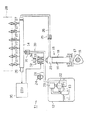
図1に示すように、本実施形態における燃料供給制御装置11は、燃料タンク12内から燃料を送り出すフィードポンプ13と、そのフィードポンプ13によって送り出された燃料を加圧して燃料配管としてのデリバリパイプ14に向けて吐出する高圧燃料ポンプ15とを備えている。前記高圧燃料ポンプ15は、排気カムシャフト16に取り付けられたカム17の回転に基づいてシリンダ18内で往復移動するプランジャ19と、シリンダ18及びプランジャ19によって区画される加圧室20とを備えている。
【0018】
この加圧室20は、低圧側燃料通路21を介して前記フィードポンプ13に接続されており、燃料タンク12内において低圧側燃料通路21の途中にはプレッシャレギュレータ22及びフィルタ23が設けられている。また、燃料タンク12外において低圧側燃料通路21の途中には同通路21を介してフィードポンプ13側から加圧室20側へ送られる燃料の脈動低減を図るためのパルセーションダンパ24が設けられている。
【0019】
一方、前記加圧室20は逆止弁25を備えた高圧側燃料通路26を介して前記デリバリパイプ14に接続されており、このデリバリパイプ14には複数(本実施形態では6つ)の燃料噴射弁27が燃料噴射手段として接続されている。そして、前記デリバリパイプ14内で蓄圧された高圧燃料は前記各燃料噴射弁27からシリンダヘッド28に設けられた各燃焼室(図示しない)内へ直接噴射されて燃料と空気とからなる混合気を生成するようになっている。さらに、前記デリバリパイプ14には同パイプ14内における高圧燃料の燃料圧力(以下、「燃圧」という。)PRを検出するための燃圧センサ29が設けられている。
【0020】
また、前記デリバリパイプ14は、リリーフ通路30を介して前記低圧側燃料通路21に接続されており、このリリーフ通路30のデリバリパイプ14側の端部にはリリーフ弁31が設けられている。このリリーフ弁31は、デリバリパイプ14内の燃圧PRが過度に高くなって当該リリーフ弁31の設定開弁圧(本実施形態では14Mpa)を越えると開弁動作するものである。そして、その開弁に伴いデリバリパイプ14内の高圧燃料を低圧側燃料通路21へ排出することで、前記デリバリパイプ14内の燃圧をリリーフ弁31の設定開弁圧以下に維持するようになっている。なお、このようにしてデリバリパイプ14内の高圧燃料が低圧側燃料通路21に流入すると同通路21内の燃圧が上昇しようとするが、その際には前記プレッシャレギュレータ22が開いて低圧側燃料通路21内は所定の圧力(低圧)に維持される。
【0021】
また、前記高圧燃料ポンプ15には、前記低圧側燃料通路21と加圧室20との間を連通・遮断する電磁スピル弁32が設けられている。この電磁スピル弁32は電磁ソレノイド33を備え、同ソレノイド33への印加電圧を制御することにより開閉動作する。即ち、電磁ソレノイド33に対する通電が停止された状態にあっては、電磁スピル弁32がコイルスプリング34の付勢力によって開き、低圧側燃料通路21と加圧室20とが連通した状態になる。この状態にあって、加圧室20の容積が大きくなる方向にプランジャ19が移動するとき(吸入行程中)には、フィードポンプ13から送り出された燃料が低圧側燃料通路21を介して加圧室20内に吸入される。
【0022】
また、加圧室20の容積が収縮する方向にプランジャ19が移動するとき(圧送行程中)には、電磁ソレノイド33に対する通電により電磁スピル弁32がコイルスプリング34の付勢力に抗して閉弁される。その結果、低圧側燃料通路21と加圧室20との間が遮断され、加圧室20内の高圧燃料が逆止弁25を開弁させることにより、当該高圧燃料は高圧側燃料通路26を介してデリバリパイプ14内へ吐出されるようになる。
【0023】
なお、前記高圧燃料ポンプ15における燃料吐出量の調整は、電磁スピル弁32の閉弁開始時期DTを制御し、圧送行程中における同スピル弁32の閉弁期間を調整することによって行われる。即ち、電磁スピル弁32の閉弁開始時期DTを早めると、前記高圧側燃料通路26及びデリバリパイプ14内の燃圧がより高められ、その結果、燃料吐出量が増加する。反対に、電磁スピル弁32の閉弁開始時期DTを遅らせて閉弁期間を短くすると燃料吐出量が減少する。従って、このように前記電磁スピル弁31の閉弁開始時期DTを制御して高圧燃料ポンプ15からの燃料吐出量を調整することにより、デリバリパイプ14内の燃料圧力(燃圧)が制御される。
【0024】
次に、前記燃料供給制御装置11の電気的構成を図2に基づいて説明する。
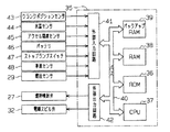
さて、前記燃料供給制御装置11には、エンジンの運転状態を制御するための電子制御ユニット(以下「ECU」という)35が設けられている。このECU35は、ROM36、CPU37、RAM38及びバックアップRAM39等を備える算術論理演算回路として構成されている。ROM36は各種制御プログラムや、それら各種制御プログラムを実行する際に参照されるマップ等が記憶されたメモリであり、CPU37はROM36に記憶された各種制御プログラムやマップ等に基づいて演算処理を実行する。本実施形態では、このCPU37により噛み込み検知手段及び昇圧手段が構成されている。
【0025】
また、RAM38はCPU37での演算結果や各センサから入力されたデータ等を一時的に記憶するメモリであり、バックアップRAM39はエンジンの停止時にその保存すべきデータ等を記憶する不揮発性のメモリである。そして、ROM36、CPU37、RAM38及びバックアップRAM39は、バス40を介して互いに接続されるとともに、外部入力回路41及び外部出力回路42と接続されている。
【0026】
外部入力回路41には、クランクポジションセンサ43、水温センサ44、アクセル開度センサ45、バッテリ46、ストップランプスイッチ47、車速センサ48、及び前記燃圧センサ29等が接続されている。一方、外部出力回路42には、前記燃料噴射弁27及び電磁スピル弁32等が接続されている。
【0027】
前記クランクポジションセンサ43は、図示しないクランクシャフトの単位時間当たりにおける回転速度、即ち、エンジン回転速度に対応した検出信号を前記外部入力回路41に入力している。前記水温センサ44は、図示しないエンジンのシリンダブロックに設けられ、エンジン冷却水温度を検出して当該冷却水温度に対応した出力電圧を前記外部入力回路41に入力している。前記アクセル開度センサ45は、図示しないアクセルペダルに取り付けられ、当該アクセルペダルの踏み込み量に比例した出力電圧を前記外部入力回路41に入力している。また、前記バッテリ46からは、その電圧が前記外部入力回路41に入力されるようになっている。
【0028】
前記ストップランプスイッチ47は、図示しないブレーキペダルの踏み込み状態を検出することにより当該検出信号を前記外部入力回路41に入力している。前記車速センサ48は、図示しないトランスミッションの出力側に設けられ、当該トランスミッションの出力軸の回転数を検出することにより当該回転数に対応した車速信号を前記外部入力回路41に入力している。また、前記燃圧センサ29からは、前記デリバリパイプ14内の燃圧に応じた出力電圧が前記外部入力回路41に入力されるようになっている。
【0029】
次に、前記燃料供給制御装置11のECU35による燃料供給制御手順について、図3に示す昇圧ルーチン及び図4に示す噛み込み検知ルーチンに基づき説明する。なお、以下に示す各ルーチンでの処理が実行される前提として、ECU35には外部入力回路41に接続されたクランクポジションセンサ43等から各々信号が適宜に入力されているものとする。
【0030】
さて、本実施形態における前記昇圧ルーチンは、例えば運転者が交差点等にて自動車を停止させたことにより内燃機関(エンジン)の自動停止条件が成立した場合に、当該時点の噛み込みフラグ(ON又はOFF)に基づきデリバリパイプ14内の燃圧を昇圧制御するようにしている。また、前記噛み込み検知ルーチンは、エンジン停止中における前記リリーフ弁31での異物の噛み込み状態の検知に基づき噛み込みフラグをON又はOFFさせるものである。従って、説明の便宜上、以下では、昇圧ルーチンにおける昇圧制御の前提となる噛み込みフラグのON/OFF設定を行う噛み込み検知ルーチンから先に説明する。
【0031】
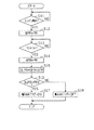
本噛み込み検知ルーチンは、予め設定した短時間毎に周期的に実行される処理であり、図4に示すように、本ルーチンがスタートすると、まずステップS11において、ECU35はエンジンが停止しているか否かを判定する。即ち、燃料噴射弁27の燃料噴射量制御処理(図示略)の停止設定、燃焼室内の混合気に対する点火制御処理(図示略)の停止設定などがなされているか否かを判定する。そして、その判定結果が否定の場合、ECU35は、エンジンが運転中であってエンジン停止状態にはないと判定し、所定時間の経過を待って前記ステップS11を繰り返し実行する。
【0032】
これに対して、前記ステップS11の判定結果が肯定の場合、ECU35は、ステップS12に処理を移行し、前記燃圧センサ29からの出力電圧に基づいて当該時点(即ち、エンジン停止直後)におけるデリバリパイプ14内の燃圧PRを算出する。そして、この算出した燃圧PRをエンジン停止直後の燃圧BPRとしてRAM38に一時的に記憶し、その後、処理をステップS13に移行する。
【0033】
そして、次のステップS13において、ECU35は、前記ステップS11でエンジンが停止したと判定してからの経過時間TCが予め設定した所定時間TX(例えば、10秒間)以上になったか否かを判定する。そして、その判定結果が否定の場合は、判定結果が肯定となるまで一定時間(例えば、1秒)周期で当該ステップS13の判定処理を繰り返し実行する。
【0034】
一方、前記ステップS13で肯定判定された場合は、処理をステップS14に移行する。そして、このステップS14において、ECU35は、前記燃圧センサ29からの出力電圧に基づきエンジン停止後所定時間(10秒)経過時点におけるデリバリパイプ14内の燃圧PRを噛み込み状態判定時の燃圧APRとしてRAM38に一時的に記憶し、その後、処理をステップS15に移行する。
【0035】
そして、次のステップS15において、ECU35は、RAM38から前記エンジン停止直後の燃圧BPRと噛み込み状態判定時の燃圧APRとを読み出し、これら両燃圧BPR,APRの差を求める。そして、ECU35は、その差をエンジン停止中における燃圧下がり代(燃圧降下の度合い)DLPRとしてバックアップRAM39に記憶した後、処理をステップS16に移行する。
【0036】
そして、次のステップS16において、ECU35は、前記燃圧下がり代DLPRが予め設定した基準燃圧下がり代PRXよりも大きいか否かを判定する。そして、その判定結果が肯定の場合は、リリーフ弁31が異物を噛み込んで不完全閉弁状態にあるため、当該リリーフ弁31の隙間からリリーフ通路30を介してデリバリパイプ14内の高圧燃料が低圧側燃料通路21側へ漏出していると判定する。そして、この場合には、処理をステップS17に移行し、このステップS17において、ECU35は、「噛み込みフラグ=ON」をバックアップRAM39に記憶し、その後、本ルーチンの処理を一旦終了する。
【0037】
一方、前記ステップS16の判定結果が否定の場合は、リリーフ弁31に異物が噛み込まれていない(又は、噛み込みの程度が微々たるものであって昇圧制御の必要がない)と判定する。そして、処理をステップS18に移行し、このステップS18において、ECU35は、「噛み込みフラグ=OFF」をバックアップRAM39に記憶し、その後、本ルーチンの処理を一旦終了する。以上のように、本実施形態ではエンジン停止中におけるデリバリパイプ14内の燃圧の下がり代(燃圧降下の度合い)DLPRに基づいてリリーフ弁31での異物の噛み込みの有無を検知している。
【0038】
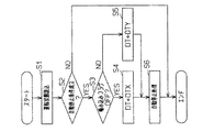
次に、図3に示す昇圧ルーチンについて説明する。
さて、本ルーチンが開始されると、ECU35は、まずステップS1において運転状態の読み込みを実行する。例えば、水温センサ44により検出されるエンジン冷却水温、アクセル開度センサ45により検出されるアクセルペダルの踏み込みの有無、バッテリ46の電圧、ストップランプスイッチ47の信号から検出されるブレーキペダルの踏み込みの有無、及び車速センサ48の信号から検出される車速を前記RAM38の作業領域に読み込む。そして、これらの読み込みが終了すると、処理を次のステップS2に移行する。
【0039】
すると、このステップS2において、ECU35は、読み込みした運転状態の内容に基づき自動停止条件が成立したか否かを判定する。本実施形態では、次のような5つの条件により自動停止条件の成立の有無を判定している。(1)エンジンが暖機後であり且つ過熱していない状態(エンジン冷却水温が予め設定された水温上限値と水温下限値の間)にあるか否か。(2)アクセルペダルが踏み込まれていない状態(アクセル開度=0)にあるか否か。(3)バッテリ46の充電量がある程度以上(予め設定された基準電圧以上)あるか否か。(4)ブレーキペダルが踏み込まれた状態(ストップランプスイッチ47からの信号がON)になっているか否か。(5)車両が停止した状態(車速センサ48からの信号に基づく車速が0km/h)になっているか否か。
【0040】
そして、本実施形態では、前記(1)〜(5)の全ての条件が肯定された場合に、ECU35は、自動停止条件が成立したと判定し、処理を次のステップS3に移行する。一方、このステップS2での判定において、前記5つの条件のうち一つでも判定結果が否定された場合、ECU35は、自動停止条件は成立していないと判定し、一旦本ルーチンの処理を終了する。
【0041】
さて、例えば交差点等での一旦停止により自動停止条件が成立した場合には、ステップS3において、ECU35は、噛み込みフラグがOFFに設定されているか否か、即ち、リリーフ弁31が異物を噛み込んでいないか否かを判定する。そして、その判定結果が肯定の場合は、リリーフ弁31が異物を噛み込んでいることもないため、新たに異物噛み込みの機会を招くおそれのあるリリーフ弁31の開弁動作を行う必要なしと判定し、処理を次のステップS4に移行する。
【0042】
すると、次のステップS4において、ECU35は、前記電磁スピル弁32の閉弁開始時期DTを所定閉弁時期DTXに設定する。なお、この所定閉弁時期DTXは前記デリバリパイプ14内の燃圧を前記リリーフ弁31の設定開弁圧(14MPa)を越えない範囲内で高圧の所定燃圧(例えば、13MPa)まで昇圧させるために設定される。
【0043】
従って、前記ステップS3での判定結果が肯定の場合、ECU35は、当該判定時点に燃圧センサ27により検出される実際の燃圧と前記所定燃圧(13MPa)との差に基づき前記所定閉弁時期DTXを算出する。そして、算出した所定閉弁時期DTXに基づき電磁スピル弁32の閉弁期間(圧送期間)を制御し、デリバリパイプ14内の燃圧を前記所定燃圧(13MPa)まで昇圧させる。
【0044】
一方、前記ステップS3での判定結果が否定の場合、ECU35は、リリーフ弁31が異物を噛み込んでいるため、当該リリーフ弁31を開弁動作させる必要ありと判定し、処理をステップS5に移行する。そして、このステップS5において、ECU35は、前記電磁スピル弁32の閉弁開始時期DTを、設定可能な閉弁時期のうち最も早い特定閉弁時期DTYに設定する。ここで、特定閉弁時期DTYは、高圧燃料ポンプ15からデリバリパイプ14へ向けて吐出される高圧燃料の供給量を最大にするために設定される。従って、電磁スピル弁32の閉弁開始時期DTが前記特定閉弁時期DTYに設定されると、デリバリパイプ14内の燃圧は急速に上昇し、ついにはリリーフ弁31の設定開弁圧(14MPa)を越えることになる。
【0045】
すると、前記リリーフ弁31が強制開弁させられ、デリバリパイプ14内から昇圧された高圧燃料がリリーフ通路30を介して低圧側燃料通路21へと排出される。また、前記リリーフ弁31の開弁動作に伴い、当該リリーフ弁31に噛み込まれていた異物も噛み込み状態から解放され、前記高圧燃料と共に低圧側燃料通路21へと排出される。そして、この高圧燃料の排出によってデリバリパイプ14内の燃圧がリリーフ弁31の設定開弁圧(14MPa)まで低下すると、当該リリーフ弁31は元の閉弁状態に復帰する。従って、以後、デリバリパイプ14内の燃圧は、リリーフ弁31が前記閉弁状態への復帰時に新たな異物を噛み込まない限り、前記設定開弁圧(14MPa)にほぼ等しい燃圧にてしばらく維持される。
【0046】
以上のように、昇圧処理に関する前記ステップS4又はステップS5の処理が終了すると、ECU35は、次のステップS6において、エンジンの自動停止処理を行う。即ち、燃料噴射弁27の燃料噴射量制御処理、燃焼室内の混合気に対する点火制御処理、電磁スピル弁32の開閉制御処理等を停止設定する。なお、このECU35によるエンジンの自動停止処理は、前記ステップS2で自動停止条件が成立したと判定(肯定判定)してから所定時間が経過したときに行われる。なお、この所定時間は、前記ステップS5で電磁スピル弁32の閉弁開始時期DTを前記特定閉弁時期DTYに設定した場合に、リリーフ弁31の設定開弁圧を越えるまでデリバリパイプ14内の燃圧が上昇するのに必要な時間を予め実験により求めることで設定される。
【0047】
そして、前記ステップS6でエンジンの自動停止処理が行われると、ECU35は、本昇圧ルーチンを一旦終了する。なお、図示はしないが、本ルーチンの終了後、ECU35は、所定条件に従い、エンジンの自動始動制御処理ルーチンを開始する。即ち、前記ステップS1と同様に運転状態の読み込みを行った後、前記ステップS2の自動停止条件成立の可否判定で使用された(1)〜(5)の各判定条件のうち一つでも判定結果が否定された場合、自動始動条件が成立したと判定し、エンジンの自動始動制御処理を行う。
【0048】
従って、本実施形態によれば、以下のような効果を奏する。
(1)リリーフ弁31に異物が噛み込まれていることを燃圧下がり代(燃圧降下の度合い)DLPRと基準燃圧下がり代PRXとの対比に基づき検知した場合に限り当該リリーフ弁31を強制開弁させるため、異物噛み込みの機会ともなるリリーフ弁31の開弁動作を必要最低限にできる。従って、リリーフ弁31の強制開弁を定期的に行う場合に比して、不要な異物噛み込みの機会を減少させることができ、成層燃焼機会の確保等により燃費等の向上を図ることができる。
【0049】
(2)燃圧下がり代(燃圧降下の度合い)DLPRが基準燃圧下がり代PRXを越えていないため異物噛み込み無しと検知された場合にもデリバリパイプ14内の燃圧をリリーフ弁31の設定開弁圧(14MPa)を越えない範囲内で高圧の所定燃圧(13MPa)まで昇圧させている。従って、その後にエンジン停止処理をした場合、エンジン停止中における燃圧降下開始圧力の値を通常の場合よりも高くでき、更にその後のエンジン始動時における成層燃焼機会を増大することができる。
【0050】
(3)前述したように、いわゆるエコラン車の場合は、走行中に自動停止制御及び自動始動制御が頻繁に行われるため、特に、前記リリーフ弁31の強制開弁を定期的に行うと、前記異物噛み込みの機会を増大してしまう。しかし、本実施形態においては、例えば自動停止直前にリリーフ弁31が異物を噛み込みしている場合に限り強制開弁させるため、より一層の燃費等の改善が期待できる。
【0051】
(4)リリーフ弁31の強制開弁に伴ってデリバリパイプ14内の燃圧をリリーフ弁31の設定開弁圧(14MPa)まで昇圧させた後にエンジンの自動停止処理を行っているので、エンジン停止中における通常の燃圧降下が通常のアイドル時燃圧(8〜10MPa)から始まる場合よりも高圧(14MPa)から始まるようにできる。従って、その後のエンジン自動始動後における成層燃焼の実行機会を従来よりも確実に増加することができ、燃費等の向上に貢献できる。
【0052】
(5)リリーフ弁31が異物を噛み込みしているか否かを検知するタイミングがエンジン停止中(従って、燃料噴射も停止中)に設定されているため、デリバリパイプ14内の燃圧PRに関して、その降下度合いDLPRの検知精度を向上することができる。従って、昇圧制御の前提となる異物噛み込みの有無に関する判定結果を正確なものにすることができる。
【0053】
(6)リリーフ弁31が異物を噛み込みしているか否かを検知するタイミングが前記エコラン車では走行中頻繁にある自動停止毎に設定されているため、リリーフ弁31における異物噛み込み検知機会を確実に増加することができる。
【0054】
なお、本実施形態は、以下のような別例に変更して具体化してもよい。
・ 前記実施形態では、いわゆるエコラン車においてエンジンの自動停止条件が成立したと判定した後の自動停止中にリリーフ弁31における異物噛み込みの有無を検知しているが、エンジン自動停止中でなく運転者のエンジン停止操作によりエンジンが停止(完全停止)されたときに異物噛み込みの有無を検知するようにしてもよい。
【0055】
・ 前記実施形態では、エンジン停止直後の燃圧BPRと噛み込み状態判定時の燃圧APRとの差である燃圧下がり代(燃圧降下度合い)DLPRを基準燃圧下がり代PRXと対比することによりリリーフ弁31が異物を噛み込みしているか否かを判定しているが、次のようにしてもよい。即ち、エンジン停止後においてリリーフ弁31が異物を噛み込みしている場合に予測できる所定時間経過時点の燃圧PRの値を基準燃圧値として予め設定しておく。そして、噛み込み状態判定時の検知燃圧値と絶対値比較をして、検知燃圧値が基準燃圧値よりも低ければ異物噛み込み有りと判定するようにしてもよい。
【0056】
・ 前記実施形態では、いわゆるエコラン車のエンジン自動停止直前に噛み込みフラグのON/OFFに基づきデリバリパイプ14内の燃圧を昇圧させる制御を行っているが、この昇圧制御のタイミングはエンジン自動停止直前でなく完全停止直前に行うようにしてもよい。
【0057】
・ また、エンジン自動停止(完全停止)直前でなく、エンジン自動始動後等の始動時に前記昇圧制御タイミングを設定してもよい。この場合には、図3のフローチャートにおいて、ステップS2で自動始動条件の成立の可否判定が行われると共に、そのステップS6では自動始動処理が行われる。このように始動時に昇圧制御を行って異物噛み込みしているリリーフ弁31を強制開弁させる場合には、異物噛み込みした状態のままエンジンを稼働させる期間を短くすることができる。
【0058】
・ 前記実施形態では、エンジン冷却水温等の前述した(1)〜(5)の5つの条件が全て成立したときにエンジン自動停止条件が成立したと判定するようにしたが、自動停止条件(又は完全停止条件)成立の判定のための条件設定は任意に変更してもよい。
【0059】
・ 前記実施形態では、噛み込みフラグOFF(噛み込み無し)のときに燃圧PRを所定燃圧(13MPa)まで昇圧させるべく電磁スピル弁32の閉弁開始時期DTを所定閉弁時期DTXにしているが、リリーフ弁31が異物を噛み込みしていないので、必ずしも燃圧PRを所定燃圧(13MPa)まで昇圧させる制御まで行う必要はない。
【0060】
・ 前記実施形態では、エンジン停止処理において燃料噴射弁27の燃料噴射量制御処理を停止設定する他に混合気への点火制御処理の停止設定等も行っているが、燃料噴射の停止設定のみでも運転は停止するので点火制御処理の停止設定等は必ずしも行わなくてよい。
【0061】
・ 前記実施形態では、いわゆるエコノミーランニングシステムが組み合わされた直噴式内燃機関における燃料供給制御装置に具体化したが、そのようなエコノミーランニングシステムが組み合わされない直噴式内燃機関における燃料供給制御装置に具体化することも可能である。
【0062】
・ また、内燃機関は6気筒に限らず、5気筒以下又は7気筒以上などに変更可能であり、さらに直噴式にも限定されない。要は、燃料配管内の燃圧が所定圧を越えるときに開弁するリリーフ弁を備える内燃機関であれば適用可能である。また、ガソリンエンジン以外にも適用可能であり、その場合の燃料噴射手段としては燃料噴射ノズルが用いられる。
【図面の簡単な説明】
【図1】 本実施形態に係る燃料供給制御装置の概要説明図。
【図2】 燃料供給制御装置の電気的構成を示すブロック図。
【図3】 昇圧ルーチンを示すフローチャート。
【図4】 噛み込み検知ルーチンを示すフローチャート。
【符号の説明】
11…燃料供給制御装置、12…燃料ポンプ、14…燃料配管としてのデリバリパイプ、27…燃料噴射手段としての燃料噴射弁、29…燃圧センサ、35…電子制御ユニット(ECU)、37…噛み込み検知手段及び昇圧手段としてのCPU、PR…燃圧。[0001]
BACKGROUND OF THE INVENTION
In the present invention, when the fuel pressure in the fuel pipe pumped from the fuel pump is increased to the set opening pressure of the relief valve, the relief valve is opened and high-pressure fuel is discharged from the fuel pipe. The present invention relates to a fuel supply control device for an internal combustion engine.
[0002]
[Prior art]
In general, in a direct injection internal combustion engine in which fuel is supplied into a combustion chamber by direct injection, it is necessary to inject fuel from a fuel injection valve against the pressure in the combustion chamber that becomes high pressure. Therefore, such a direct injection internal combustion engine employs a fuel supply control device that pressurizes the fuel to a high pressure and supplies the fuel to the fuel injection valve. That is, in this fuel supply control device, the fuel delivered from the fuel tank by the feed pump is pressurized by the high-pressure pump, and the pressurized high-pressure fuel is supplied to the delivery pipe connected to the fuel injection valve. When performing stratified combustion, the high-pressure fuel accumulated in the delivery pipe is injected into the combustion chamber from the fuel injection valve during the compression stroke, and when performing homogeneous combustion, the high-pressure fuel is injected during the intake stroke. It comes to be injected.
[0003]
On the other hand, the fuel supply control device is provided with a relief passage having a relief valve that opens at a predetermined valve opening pressure so as to connect the delivery pipe and the low-pressure side fuel passage (or fuel pump). . When the fuel pressure in the delivery pipe becomes excessively high and exceeds the set valve opening pressure, the relief valve opens and the high-pressure fuel in the delivery pipe is released to the low-pressure side fuel passage so that the inside of the delivery pipe The fuel pressure is appropriately reduced.
[0004]
By the way, since the relief valve opens when the fuel pressure in the delivery pipe becomes excessively high and exceeds the set valve opening pressure, the relief valve is closed unless the fuel pressure becomes so high. The valve state will be maintained. For this reason, if such a valve-closed state lasts for a long period of time, if a foreign object (for example, metal powder contained in the fuel) is bitten when the valve is closed after the valve-opening operation, an incomplete valve-closed state may occur. It will be maintained for a long time. Therefore, the fuel pressure in the delivery pipe gradually leaks from the incompletely closed relief valve, and the fuel pressure in the delivery pipe gradually decreases. Therefore, even if the operation state is a state that enables stratified combustion, if the fuel pressure is insufficient for fuel injection during the compression stroke due to the decrease in leakage of the fuel pressure, the fuel injection during the intake stroke is performed. Therefore, it has been necessary to perform homogeneous combustion, resulting in a situation in which the desired fuel consumption cannot be improved.
[0005]
Therefore, recently, every time the fuel pressure in the delivery pipe reaches a predetermined operating state (for example, an engine stop state), the fuel pressure in the delivery pipe is periodically increased to the set valve opening pressure, and foreign matter may be caught. There has been proposed a technique for forcibly opening a certain relief valve. For example, Japanese Patent Laid-Open No. 6-249101 discloses a technique for forcibly increasing the fuel pressure every time the engine is stopped, and Japanese Patent Laid-Open No. 10-176618 discloses a technique for forcibly increasing the fuel pressure every time the engine is started. Has been.
[0006]
[Problems to be solved by the invention]
However, as with the fuel supply control devices disclosed in the above publications, the technique for periodically forcibly opening the relief valve is not limited to the case where the relief valve bites foreign matter, and does not bite foreign matter. Even in this case, the relief valve is forcibly opened. For this reason, it may happen that the foreign matter is bitten into the relief valve conversely with the forced valve opening operation when no foreign matter is bitten.
[0007]
In other words, the forced opening of the relief valve can forcibly remove the foreign matter biting into the relief valve, while periodically performing such a forced opening valve increases the chance of foreign matter biting. Was causing serious problems. Such a problem is not limited to the direct injection engine as described above, but is generally common in the actual situation as long as the internal combustion engine has a relief valve even in an internal combustion engine that injects fuel in the intake passage. It was a thing.
[0008]
The present invention has been made to solve the above-described problem, and is an internal combustion engine that can appropriately control the forced valve opening timing of the relief valve to reduce the chance of foreign object biting, and can reliably improve fuel consumption. The object is to provide a fuel supply control device.
[0009]
[Means for Solving the Problems]
In order to achieve the above object, according to the first aspect of the present invention, the fuel pressure in the fuel pipe for supplying the high pressure fuel pumped from the fuel pump to the internal combustion engine via the fuel injection means is connected to the fuel pipe. In the fuel supply control device for an internal combustion engine, the relief valve opens when the relief valve set opening pressure of the relief passage is exceeded, and the high-pressure fuel in the fuel pipe is discharged through the relief passage. Biting detection means for detecting whether or not foreign matter is caught in the relief valve, and when the biting detection means detects that foreign matter is caught, the fuel pressure in the fuel pipe is set to open the relief valve. Boosting means for boosting the pressure so as to exceed the pressure, and the boosting means stops the engine from boosting the fuel pressure in the fuel pipe based on the detection result of foreign object biting.right beforeThe gist is to do.
[0010]
Therefore, according to the first aspect of the present invention, the relief valve is opened only when the relief valve bites foreign matter and the foreign matter is removed, so that the relief valve is forcedly opened more than necessary. It is possible to improve the fuel consumption and the like by reducing the increase in unnecessary foreign matter biting.
[0011]
According to a second aspect of the present invention, in the first aspect of the present invention, the pressure increasing means detects the fuel in the fuel pipe at a predetermined timing when the biting detection means detects that no foreign matter is bitten. The gist is to increase the pressure to a predetermined high fuel pressure within a range not exceeding the set valve opening pressure of the relief valve. Therefore, according to the second aspect of the present invention, the fuel pressure in the fuel pipe is increased to a predetermined high fuel pressure within a range that does not exceed the set valve opening pressure of the relief valve even when the relief valve does not bite foreign matter. Therefore, even if the internal combustion engine is subsequently shut down, the value of the fuel pressure drop start pressure during the shutdown can be made higher than in the normal case.
[0012]
According to a third aspect of the present invention, in the first or second aspect of the invention, the internal combustion engine is configured such that the high-pressure fuel accumulated in the fuel pipe is directly injected into the combustion chamber from the fuel injection means. The gist of the invention is that when the predetermined condition is satisfied in the operation state of the internal combustion engine, the operation is automatically stopped or automatically started. Therefore, according to the third aspect of the invention, an automobile (hereinafter referred to as an “eco-run vehicle”) that combines an economy running system that performs automatic stop / automatic start control of the internal combustion engine during traveling with respect to the direct injection internal combustion engine. )), Further improvement in fuel consumption can be expected.
In particular, in an eco-run vehicle, the absolute pressure of the fuel pressure in the fuel pipe can be increased immediately before the engine is automatically stopped, and the opportunity for executing stratified combustion after the engine is automatically started can be increased.
[0014]
Claims4The invention described in
[0015]
Claims5The invention described in
Claims6The invention described in claim 15The fuel supply control device for an internal combustion engine according to any one of the above, wherein the fuel pressure in the fuel pipe immediately after the engine is stopped is a first fuel pressure, and the engine is stopped after a predetermined period of time has passed since the stop. When the fuel pressure in the fuel pipe is the second fuel pressure, the biting detection means has a difference between the first fuel pressure and the second fuel pressure greater than a preset reference pressure difference when the engine is stopped. If the difference between the first fuel pressure and the second fuel pressure is smaller than the reference pressure difference when it is determined that there is foreign matter biting in the relief valve and the engine is stopped, foreign matter biting occurs in the relief valve. The boosting means is determined after the biting detection means determines that a foreign object has been caught in the relief valve.Just before the restarted engine operation is stopped,The fuel pressure is increased by the fuel pump until the fuel pressure in the fuel pipe exceeds the set valve opening pressure of the relief valve, and the engine operation is resumed after it is determined by the biting detection means that no foreign matter is caught in the relief valve. When the overall operating state including the operating state of the internal combustion engine and the operating state of the vehicle has shifted to a predetermined operating state, the pressure increase is not performed until the fuel pressure in the fuel pipe exceeds the relief valve set opening pressure It is the gist of that.
Claims7The invention described in claim 15In the fuel supply control device for an internal combustion engine according to any one of the above, the fuel pressure P in the fuel pipe when a predetermined period has elapsed immediately after the engine is stopped is defined as the fuel pressure P. When the fuel pressure P is smaller than a preset reference pressure, it is determined that foreign matter is caught in the relief valve. When the fuel pressure P is greater than the reference pressure when the engine is stopped, The pressure boosting means determines that the foreign matter is caught in the relief valve by the biting detection means.Just before the restarted engine operation is stopped,The fuel pressure in the fuel pipe is increased by the fuel pump until it exceeds the set valve opening pressure of the relief valve, and the engine operation is resumed after it is determined by the biting detection means that no foreign matter is caught in the relief valve. When the overall operating state including the operating state of the internal combustion engine and the operating state of the vehicle has shifted to a predetermined operating state, the pressure increase is not performed until the fuel pressure in the fuel pipe exceeds the relief valve set opening pressure It is the gist of that.
Claims8The invention described in claim 15The fuel supply control device for an internal combustion engine according to any one of the above, wherein the fuel pressure in the fuel pipe immediately after the engine stop by the driver's engine stop operation is the first fuel pressure, and the engine is stopped by the driver's engine stop operation. The difference between the first fuel pressure and the second fuel pressure is set in advance when the engine is stopped, with the fuel pressure in the fuel pipe at the time when a predetermined period has passed immediately after being used as the second fuel pressure. When the pressure difference is larger than the reference pressure difference, it is determined that foreign matter is caught in the relief valve. When the difference between the first fuel pressure and the second fuel pressure is smaller than the reference pressure difference when the engine is stopped, the relief valve The pressure boosting means determines the pressure of the fuel in the fuel pipe when it is determined by the biting detection means that the foreign matter is caught in the relief valve. Re The pressure is increased by the fuel pump until the valve opening set pressure is exceeded, and when it is determined by the biting detection means that no foreign matter is caught in the relief valve, the fuel pressure in the fuel pipe is The gist is that the pressure increase is not performed until the set valve opening pressure is exceeded.
Claims9The invention described in claim 15In the fuel supply control device for an internal combustion engine according to any one of the above, the biting detection unit is configured to detect a fuel pressure in the fuel pipe when a predetermined period has elapsed immediately after the engine is stopped by the engine stop operation of the driver. When the pressure is lower than a preset reference pressure, it is determined that foreign matter has been caught in the relief valve, and the fuel in the fuel pipe when a predetermined period has passed immediately after the engine is stopped by the driver's engine stop operation When the pressure is greater than the reference pressure, it is determined that no foreign object has been caught in the relief valve, and the pressure increasing means has the foreign substance bite in the relief valve by the biting detection means. When the determination is made, the fuel pressure in the fuel pipe is increased by the fuel pump until it exceeds the set opening pressure of the relief valve, and foreign matter is caught in the relief valve by the biting detection means. When it is determined that where there is no fuel pressure in the fuel pipe is a gist that is not conducted the boosting up exceeds the set valve opening pressure of the relief valve.
[0016]
DETAILED DESCRIPTION OF THE INVENTION
Hereinafter, the present invention is specifically applied to a fuel supply control device in a direct injection type 6-cylinder gasoline engine to which an economy running system that performs automatic stop / automatic start control of an internal combustion engine (hereinafter also referred to as an “engine”) during traveling is applied. A simplified embodiment will be described with reference to FIGS.
[0017]
As shown in FIG. 1, the fuel
[0018]
The pressurizing
[0019]
On the other hand, the pressurizing
[0020]
The
[0021]
The high-
[0022]
When the
[0023]
The fuel discharge amount in the high-
[0024]
Next, the electrical configuration of the fuel
The fuel
[0025]
The
[0026]
A crank position sensor 43, a
[0027]
The crank position sensor 43 inputs a detection signal corresponding to a rotational speed per unit time of a crankshaft (not shown), that is, an engine rotational speed, to the
[0028]
The stop lamp switch 47 inputs the detection signal to the
[0029]
Next, the fuel supply control procedure by the
[0030]
Now, the boost routine in the present embodiment, for example, when the automatic stop condition of the internal combustion engine (engine) is satisfied by the driver stopping the automobile at an intersection or the like, the biting flag (ON or OFF), the fuel pressure in the
[0031]
This biting detection routine is a process that is periodically executed every preset short time. As shown in FIG. 4, when this routine starts, first, in step S11, the
[0032]
On the other hand, if the determination result in step S11 is affirmative, the
[0033]
In the next step S13, the
[0034]
On the other hand, if a positive determination is made in step S13, the process proceeds to step S14. In this step S14, the
[0035]
In the next step S15, the
[0036]
In the next step S16, the
[0037]
On the other hand, if the determination result in step S16 is negative, it is determined that no foreign matter is caught in the relief valve 31 (or the degree of biting is slight and there is no need for pressure increase control). Then, the process proceeds to step S18, and in this step S18, the
[0038]
Next, the boosting routine shown in FIG. 3 will be described.
When this routine is started, the
[0039]
Then, in this step S2, the
[0040]
And in this embodiment, when all the conditions of said (1)-(5) are affirmed, ECU35 determines with the automatic stop condition having been satisfied, and transfers a process to following step S3. On the other hand, in the determination in step S2, if even one of the five conditions is negative, the
[0041]
For example, when the automatic stop condition is satisfied by temporarily stopping at an intersection or the like, in step S3, the
[0042]
Then, in the next step S4, the
[0043]
Therefore, if the determination result in step S3 is affirmative, the
[0044]
On the other hand, if the determination result in step S3 is negative, the
[0045]
Then, the
[0046]
As described above, when the process of step S4 or step S5 related to the pressure increasing process is finished, the
[0047]
When the engine automatic stop process is performed in step S6, the
[0048]
Therefore, according to the present embodiment, the following effects can be obtained.
(1) The
[0049]
(2) Fuel pressure drop allowance (degree of fuel pressure drop) Even if it is detected that no foreign matter is caught because DLPR does not exceed the reference fuel pressure drop allowance PRX, the fuel pressure in the
[0050]
(3) As described above, in the case of a so-called eco-run vehicle, since automatic stop control and automatic start control are frequently performed during traveling, in particular, when the forced opening of the
[0051]
(4) Since the engine is automatically stopped after the fuel pressure in the
[0052]
(5) Since the timing for detecting whether or not the
[0053]
(6) Since the timing for detecting whether or not the
[0054]
The present embodiment may be embodied by changing to another example as described below.
In the embodiment, in the so-called eco-run vehicle, the presence or absence of foreign matter biting in the
[0055]
In the above embodiment, the
[0056]
In the above-described embodiment, control is performed to increase the fuel pressure in the
[0057]
The boost control timing may be set not at the time of automatic engine stop (complete stop) but at the time of start such as after the automatic engine start. In this case, in the flowchart of FIG. 3, it is determined whether or not the automatic start condition is established in step S2, and an automatic start process is performed in step S6. In this way, when the pressure increase control is performed at the time of starting and the
[0058]
In the embodiment, it is determined that the engine automatic stop condition is satisfied when all of the five conditions (1) to (5) described above such as the engine coolant temperature are satisfied, but the automatic stop condition (or The condition setting for determining whether or not the complete stop condition is satisfied may be arbitrarily changed.
[0059]
In the above embodiment, the valve closing start timing DT of the
[0060]
In the above-described embodiment, in addition to stopping the fuel injection amount control process of the
[0061]
In the above embodiment, the fuel supply control device in the direct injection internal combustion engine combined with the so-called economy running system is embodied, but the fuel supply control device in the direct injection internal combustion engine not combined with such an economy running system is embodied. It is also possible to do.
[0062]
The internal combustion engine is not limited to 6 cylinders, and can be changed to 5 cylinders or less, 7 cylinders or more, and is not limited to a direct injection type. In short, any internal combustion engine having a relief valve that opens when the fuel pressure in the fuel pipe exceeds a predetermined pressure is applicable. Further, the present invention can be applied to other than a gasoline engine, and a fuel injection nozzle is used as a fuel injection means in that case.
[Brief description of the drawings]
FIG. 1 is a schematic explanatory diagram of a fuel supply control apparatus according to an embodiment.
FIG. 2 is a block diagram showing an electrical configuration of a fuel supply control device.
FIG. 3 is a flowchart showing a boosting routine.
FIG. 4 is a flowchart showing a biting detection routine.
[Explanation of symbols]
DESCRIPTION OF
Claims (9)
前記リリーフ弁での異物の噛み込みの有無を検知する噛み込み検知手段と、
この噛み込み検知手段が異物噛み込み有りと検知したときに前記燃料配管内の燃料圧力が前記リリーフ弁の設定開弁圧を超えるように昇圧する昇圧手段とを備え、
この昇圧手段は、異物噛み込み有りの検知結果に基づく前記燃料配管内の燃料圧力の昇圧を機関停止直前に行う
ことを特徴とする内燃機関の燃料供給制御装置。When the fuel pressure in the fuel pipe for supplying the high-pressure fuel pumped from the fuel pump to the internal combustion engine via the fuel injection means exceeds the set opening pressure of the relief valve of the relief passage connected to the fuel pipe, the relief valve In the fuel supply control device for an internal combustion engine, in which the valve is opened so that the high-pressure fuel in the fuel pipe is discharged through the relief passage.
Biting detection means for detecting the presence or absence of foreign matter biting in the relief valve;
A boosting means for boosting the fuel pressure in the fuel pipe so as to exceed the set valve opening pressure of the relief valve when the biting detection means detects the presence of foreign object biting;
The boosting means boosts the fuel pressure in the fuel pipe immediately before the engine is stopped based on a detection result of foreign object jamming.
機関停止直後の燃料配管内の燃料圧力を第1燃料圧力とし、同停止の直後から所定の期間が経過した後の機関停止中の燃料配管内の燃料圧力を第2燃料圧力として、
前記噛み込み検知手段は、機関停止したときに第1燃料圧力と第2燃料圧力との差が予め設定された基準圧力差よりも大きいとき、リリーフ弁での異物の噛み込みがある旨判定し、機関停止したときに第1燃料圧力と第2燃料圧力との差が基準圧力差よりも小さいとき、リリーフ弁に異物の噛み込みが生じていない旨判定するものであり、
前記昇圧手段は、前記噛み込み検知手段によりリリーフ弁に異物の噛み込みが生じている旨判定された後に再開された機関運転が停止される直前に、燃料配管内の燃料圧力がリリーフ弁の設定開弁圧を超えるまで燃料ポンプにより昇圧し、前記噛み込み検知手段によりリリーフ弁に異物の噛み込みが生じていない旨判定された後に機関運転が再開されて内燃機関の運転状態及び車両の運転状態を含む全体運転状態が所定の運転状態に移行したとき、燃料配管内の燃料圧力がリリーフ弁の設定開弁圧を超えるまでの前記昇圧を行わないものである
ことを特徴とする内燃機関の燃料供給制御装置。In the fuel supply control device for an internal combustion engine according to any one of claims 1 to 5 ,
The fuel pressure in the fuel pipe immediately after the engine stop is set as the first fuel pressure, and the fuel pressure in the fuel pipe during the engine stop after a predetermined period of time immediately after the stop is set as the second fuel pressure.
The biting detection means determines that there is a foreign matter biting in the relief valve when the difference between the first fuel pressure and the second fuel pressure is greater than a preset reference pressure difference when the engine is stopped. When the engine is stopped, when the difference between the first fuel pressure and the second fuel pressure is smaller than the reference pressure difference, it is determined that no foreign matter is caught in the relief valve,
The boosting means is configured so that the fuel pressure in the fuel pipe is set to the relief valve immediately before the restarted engine operation is stopped after it is determined by the biting detection means that the foreign matter is caught in the relief valve. The pressure is increased by the fuel pump until the valve opening pressure is exceeded, and the engine operation is resumed after it is determined by the biting detection means that no foreign matter is caught in the relief valve, and the internal combustion engine and vehicle operating conditions are resumed. The fuel of the internal combustion engine is characterized by not performing the pressure increase until the fuel pressure in the fuel pipe exceeds the set valve opening pressure of the relief valve when the entire operation state including Supply control device.
機関停止直後から所定の期間が経過したときの燃料配管内の燃料圧力を燃料圧力Pとして、
前記噛み込み検知手段は、機関停止したときに燃料圧力Pが予め設定された基準圧力よりも小さいとき、リリーフ弁に異物の噛み込みが生じている旨判定し、機関停止したときに燃料圧力Pが基準圧力よりも大きいとき、リリーフ弁に異物の噛み込みが生じていない旨判定するものであり、
前記昇圧手段は、前記噛み込み検知手段によりリリーフ弁に異物の噛み込みが生じている旨判定された後に再開された機関運転が停止される直前に、燃料配管内の燃料圧力をリリーフ弁の設定開弁圧を超えるまで燃料ポンプにより昇圧し、前記噛み込み検知手段によりリリーフ弁に異物の噛み込みが生じていない旨判定された後に機関運転が再開されて内燃機関の運転状態及び車両の運転状態を含む全体運転状態が所定の運転状態に移行したとき、燃料配管内の燃料圧力がリリーフ弁の設定開弁圧を超えるまでの前記昇圧を行わないものである
ことを特徴とする内燃機関の燃料供給制御装置。In the fuel supply control device for an internal combustion engine according to any one of claims 1 to 5 ,
As fuel pressure P, the fuel pressure in the fuel pipe when a predetermined period has passed since the engine stopped
The biting detection means determines that foreign matter is bitten in the relief valve when the fuel pressure P is smaller than a preset reference pressure when the engine is stopped, and the fuel pressure P when the engine is stopped. When the pressure is larger than the reference pressure, it is determined that no foreign matter is caught in the relief valve,
The boosting means sets the fuel pressure in the fuel pipe immediately before the restarted engine operation is stopped after it is determined by the biting detection means that foreign matter is caught in the relief valve. The pressure is increased by the fuel pump until the valve opening pressure is exceeded, and the engine operation is resumed after it is determined by the biting detection means that no foreign matter is caught in the relief valve, and the internal combustion engine and vehicle operating conditions are resumed. The fuel of the internal combustion engine is characterized by not performing the pressure increase until the fuel pressure in the fuel pipe exceeds the set valve opening pressure of the relief valve when the entire operation state including Supply control device.
運転者の機関停止操作による機関停止直後の燃料配管内の燃料圧力を第1燃料圧力とし、運転者の機関停止操作による機関停止直後から所定の期間が経過したときの燃料配管内の燃料圧力を第2燃料圧力として、
前記噛み込み検知手段は、機関停止時に第1燃料圧力と第2燃料圧力との差が予め設定された基準圧力差よりも大きいとき、リリーフ弁に異物の噛み込みが生じている旨判定し、機関停止時に第1燃料圧力と第2燃料圧力との差が基準圧力差よりも小さいとき、リリーフ弁に異物の噛み込みが生じていない旨判定するものであり、
前記昇圧手段は、前記噛み込み検知手段によりリリーフ弁に異物の噛み込みが生じている旨判定されたとき、燃料配管内の燃料圧力をリリーフ弁の設定開弁圧を超えるまで燃料ポンプにより昇圧し、前記噛み込み検知手段によりリリーフ弁に異物の噛み込みが生じていない旨判定されたとき、燃料配管内の燃料圧力がリリーフ弁の設定開弁圧を超えるまでの前記昇圧を行わないものである
ことを特徴とする内燃機関の燃料供給制御装置。In the fuel supply control device for an internal combustion engine according to any one of claims 1 to 5 ,
The fuel pressure in the fuel pipe immediately after the engine stop by the driver's engine stop operation is defined as the first fuel pressure, and the fuel pressure in the fuel pipe when a predetermined period has elapsed immediately after the engine stop by the driver's engine stop operation is As the second fuel pressure,
When the difference between the first fuel pressure and the second fuel pressure is larger than a preset reference pressure difference when the engine is stopped, the biting detection means determines that foreign matter is bitten in the relief valve; When the difference between the first fuel pressure and the second fuel pressure is smaller than the reference pressure difference when the engine is stopped, it is determined that no foreign matter is caught in the relief valve;
The boosting means boosts the fuel pressure in the fuel pipe by the fuel pump until it exceeds the set opening pressure of the relief valve when it is determined by the biting detection means that the foreign matter is caught in the relief valve. When the biting detection means determines that no foreign matter bites into the relief valve, the boosting is not performed until the fuel pressure in the fuel pipe exceeds the set valve opening pressure of the relief valve. A fuel supply control apparatus for an internal combustion engine.
前記噛み込み検知手段は、運転者の機関停止操作による機関停止直後から所定の期間が経過したときの燃料配管内の燃料圧力が予め設定された基準圧力よりも小さいとき、リリーフ弁に異物の噛み込みが生じている旨判定し、運転者の機関停止操作による機関停止直後から所定の期間が経過したときの燃料配管内の燃料圧力が基準圧力よりも大きいとき、リリーフ弁に異物の噛み込みが生じていない旨判定するものであり、
前記昇圧手段は、前記噛み込み検知手段によりリリーフ弁に異物の噛み込みが生じている旨判定されたとき、燃料配管内の燃料圧力をリリーフ弁の設定開弁圧を超えるまで燃料ポンプにより昇圧し、前記噛み込み検知手段によりリリーフ弁に異物の噛み込みが生じていない旨判定されたとき、燃料配管内の燃料圧力がリリーフ弁の設定開弁圧を超えるまでの前記昇圧を行わないものである
ことを特徴とする内燃機関の燃料供給制御装置。In the fuel supply control device for an internal combustion engine according to any one of claims 1 to 5 ,
When the fuel pressure in the fuel pipe is less than a preset reference pressure when a predetermined period has passed immediately after the engine is stopped by the engine stop operation by the driver, the biting detection means When the fuel pressure in the fuel pipe is greater than the reference pressure when a predetermined period has elapsed since the engine was stopped due to the engine stop operation by the driver, foreign matter is caught in the relief valve. It is determined that it has not occurred,
The boosting means boosts the fuel pressure in the fuel pipe by the fuel pump until it exceeds the set opening pressure of the relief valve when it is determined by the biting detection means that the foreign matter is caught in the relief valve. When the biting detection means determines that no foreign matter bites into the relief valve, the boosting is not performed until the fuel pressure in the fuel pipe exceeds the set valve opening pressure of the relief valve. A fuel supply control apparatus for an internal combustion engine.
Priority Applications (1)
| Application Number | Priority Date | Filing Date | Title |
|---|---|---|---|
| JP2001054449A JP4635351B2 (en) | 2001-02-28 | 2001-02-28 | Fuel supply control device for internal combustion engine |
Applications Claiming Priority (1)
| Application Number | Priority Date | Filing Date | Title |
|---|---|---|---|
| JP2001054449A JP4635351B2 (en) | 2001-02-28 | 2001-02-28 | Fuel supply control device for internal combustion engine |
Publications (2)
| Publication Number | Publication Date |
|---|---|
| JP2002256943A JP2002256943A (en) | 2002-09-11 |
| JP4635351B2 true JP4635351B2 (en) | 2011-02-23 |
Family
ID=18914779
Family Applications (1)
| Application Number | Title | Priority Date | Filing Date |
|---|---|---|---|
| JP2001054449A Expired - Fee Related JP4635351B2 (en) | 2001-02-28 | 2001-02-28 | Fuel supply control device for internal combustion engine |
Country Status (1)
| Country | Link |
|---|---|
| JP (1) | JP4635351B2 (en) |
Families Citing this family (6)
| Publication number | Priority date | Publication date | Assignee | Title |
|---|---|---|---|---|
| JP4508020B2 (en) | 2005-07-13 | 2010-07-21 | トヨタ自動車株式会社 | Diagnostic device for electromagnetic relief valve in fuel supply system |
| JP5093644B2 (en) * | 2006-11-24 | 2012-12-12 | トヨタ自動車株式会社 | Fuel cell system |
| JP5282468B2 (en) * | 2008-07-24 | 2013-09-04 | マツダ株式会社 | Diesel engine automatic stop control method and automatic stop device |
| EP2492480B1 (en) * | 2009-10-23 | 2015-11-25 | Bosch Corporation | Control device for internal combustion engine |
| JP2011132941A (en) * | 2009-11-26 | 2011-07-07 | Nippon Soken Inc | Pressure control valve |
| DE102016208088A1 (en) * | 2016-05-11 | 2017-11-16 | Robert Bosch Gmbh | Method for controlling a fuel supply system |
Citations (2)
| Publication number | Priority date | Publication date | Assignee | Title |
|---|---|---|---|---|
| JP2000045839A (en) * | 1998-07-24 | 2000-02-15 | Nissan Motor Co Ltd | Control device of variable pressure regulator for internal combustion engine |
| JP2000320366A (en) * | 1999-05-14 | 2000-11-21 | Nissan Motor Co Ltd | Automatic engine stop/restart type vehicle |
Family Cites Families (3)
| Publication number | Priority date | Publication date | Assignee | Title |
|---|---|---|---|---|
| JP3191471B2 (en) * | 1993-02-26 | 2001-07-23 | 株式会社デンソー | Fuel injection device for diesel engine |
| JPH0942105A (en) * | 1995-08-02 | 1997-02-10 | Hino Motors Ltd | Fuel leakage detector |
| JP3572937B2 (en) * | 1998-04-28 | 2004-10-06 | トヨタ自動車株式会社 | Fuel pressure control device for accumulator type fuel injection mechanism |
-
2001
- 2001-02-28 JP JP2001054449A patent/JP4635351B2/en not_active Expired - Fee Related
Patent Citations (2)
| Publication number | Priority date | Publication date | Assignee | Title |
|---|---|---|---|---|
| JP2000045839A (en) * | 1998-07-24 | 2000-02-15 | Nissan Motor Co Ltd | Control device of variable pressure regulator for internal combustion engine |
| JP2000320366A (en) * | 1999-05-14 | 2000-11-21 | Nissan Motor Co Ltd | Automatic engine stop/restart type vehicle |
Also Published As
| Publication number | Publication date |
|---|---|
| JP2002256943A (en) | 2002-09-11 |
Similar Documents
| Publication | Publication Date | Title |
|---|---|---|
| US8881707B2 (en) | Fail-safe controller for direct injection engine | |
| US7801672B2 (en) | After-stop fuel pressure control device of direct injection engine | |
| US5918578A (en) | Fuel feeding system for internal combustion engine | |
| US7328687B2 (en) | Fuel supply apparatus for internal combustion engine | |
| JP6700590B2 (en) | Engine fuel supply | |
| US7698054B2 (en) | Start-up control device and start-up control method for internal combustion engine | |
| US7565898B2 (en) | Controller for direct injection engine and controlling method | |
| US20140251280A1 (en) | Control apparatus for internal combustion engine and control method for internal combustion engine | |
| US20100100303A1 (en) | Fuel Injection Control Device For Diesel Engine | |
| JP4023020B2 (en) | Fuel pressure control device for high pressure fuel injection system | |
| JP2009079514A (en) | Fuel pressure control device for cylinder injection type internal combustion engine | |
| US6748924B2 (en) | Method and system for controlling fuel injection | |
| JP3786002B2 (en) | High pressure fuel supply device for internal combustion engine | |
| JP3814916B2 (en) | Fuel injection device for internal combustion engine | |
| JP4635351B2 (en) | Fuel supply control device for internal combustion engine | |
| JP2003239823A (en) | Accumulator fuel injector | |
| JP3772824B2 (en) | Fuel injection control device for in-cylinder internal combustion engine | |
| JP4529943B2 (en) | Fuel injection control device for internal combustion engine | |
| JP2010025088A (en) | Automatic stop control method and automatic stop device for diesel engine | |
| JP3391564B2 (en) | Fuel pressure control system for high pressure injection engine | |
| JP2010133265A (en) | Fuel supply system for internal combustion engine | |
| JPH0777119A (en) | Fuel feeder for internal combustion engine | |
| JP2011208560A (en) | Fuel supply control device of cylinder injection engine with idle stop function | |
| JP4296732B2 (en) | In-cylinder injection internal combustion engine start-up control device | |
| JP4058301B2 (en) | High pressure fuel supply device for internal combustion engine |
Legal Events
| Date | Code | Title | Description |
|---|---|---|---|
| A621 | Written request for application examination |
Free format text: JAPANESE INTERMEDIATE CODE: A621 Effective date: 20080119 |
|
| A977 | Report on retrieval |
Free format text: JAPANESE INTERMEDIATE CODE: A971007 Effective date: 20090831 |
|
| A131 | Notification of reasons for refusal |
Free format text: JAPANESE INTERMEDIATE CODE: A131 Effective date: 20090908 |
|
| A521 | Written amendment |
Free format text: JAPANESE INTERMEDIATE CODE: A523 Effective date: 20091106 |
|
| A131 | Notification of reasons for refusal |
Free format text: JAPANESE INTERMEDIATE CODE: A131 Effective date: 20100209 |
|
| A521 | Written amendment |
Free format text: JAPANESE INTERMEDIATE CODE: A523 Effective date: 20100412 |
|
| TRDD | Decision of grant or rejection written | ||
| A01 | Written decision to grant a patent or to grant a registration (utility model) |
Free format text: JAPANESE INTERMEDIATE CODE: A01 Effective date: 20101026 |
|
| A01 | Written decision to grant a patent or to grant a registration (utility model) |
Free format text: JAPANESE INTERMEDIATE CODE: A01 |
|
| A61 | First payment of annual fees (during grant procedure) |
Free format text: JAPANESE INTERMEDIATE CODE: A61 Effective date: 20101108 |
|
| FPAY | Renewal fee payment (event date is renewal date of database) |
Free format text: PAYMENT UNTIL: 20131203 Year of fee payment: 3 |
|
| FPAY | Renewal fee payment (event date is renewal date of database) |
Free format text: PAYMENT UNTIL: 20131203 Year of fee payment: 3 |
|
| LAPS | Cancellation because of no payment of annual fees |