JP4635337B2 - Control method of clamping pressure of seal roll in continuous strip processing furnace - Google Patents
Control method of clamping pressure of seal roll in continuous strip processing furnace Download PDFInfo
- Publication number
- JP4635337B2 JP4635337B2 JP2000389159A JP2000389159A JP4635337B2 JP 4635337 B2 JP4635337 B2 JP 4635337B2 JP 2000389159 A JP2000389159 A JP 2000389159A JP 2000389159 A JP2000389159 A JP 2000389159A JP 4635337 B2 JP4635337 B2 JP 4635337B2
- Authority
- JP
- Japan
- Prior art keywords
- pressure
- strip
- furnace
- clamping pressure
- meandering
- Prior art date
- Legal status (The legal status is an assumption and is not a legal conclusion. Google has not performed a legal analysis and makes no representation as to the accuracy of the status listed.)
- Expired - Fee Related
Links
Images

Landscapes
- Heat Treatment Of Strip Materials And Filament Materials (AREA)
Description
【0001】
【発明の属する技術分野】
この発明はストリップ連続処理炉において炉内雰囲気維持用に設けるシールロールの、挟圧力を制御する方法に関する。
【0002】
【従来の技術】
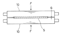
たとえばストリップの光輝焼鈍や無酸化焼鈍などをおこなう連続処理炉においては、炉内を無酸化雰囲気に維持するために、炉の入口部と出口部にストリップを挟圧してシールするシールロールを設ける。図10はその一例を示し、シリコンゴム等の弾性材を表面にコーティングした一対のシールロール10,10でストリップSを挟圧して、炉端部のストリップ通過用開口部をシールするものであり、エアシリンダ等の駆動手段によるロール相互の挟圧力Fを大きくするほど、ロール間のすきまGは小さくなり、雰囲気ガスシールの点では好ましい。
【0003】
一方上記の連続処理炉においては、高速で走行するストリップが、板巾方向に変位する蛇行状態が発生するので、この蛇行を修正するために炉内あるいは炉外近傍部に、ストリップが巻掛けられるロールを傾動させて蛇行量を少量に抑えるステアリングロールが設けられるが、上記のシールロールによるストリップの挟圧力Fが大きいと、ステアリングロールによる蛇行修正が阻害されて蛇行量が過大となったり、シールロールが蛇行の原因となることがある。そこで蛇行修正を確実にするためには挟圧力Fを小さくせざるを得ず、炉内雰囲気ガスの漏出量が大きくなったり、外気が炉内に侵入するなどの問題があった。
【0004】
【発明が解決しようとする課題】
この発明は上記従来の問題点を解決しようとするもので、ステアリングロールによる蛇行修正を阻害することなくシールロールによるシール性を良好に維持できるストリップ連続処理炉におけるシールロールの挟圧力制御方法を提供することを目的とする。
【0005】
【課題を解決するための手段】
上記目的を達成するために、請求項1記載のストリップ連続処理炉におけるシールロールの挟圧力制御方法は、ストリップの蛇行修正用のステアリングロールをそなえるとともに、炉の出入口部に、表面部を弾性材で被覆されストリップの両面を所定の設定挟圧力で挟圧するシールロールをそなえたストリップ連続処理炉において、走行中のストリップの蛇行量を検出し、この蛇行量検出値が所定の閾値を越えたとき、前記シールロールによるストリップの挟圧力を所定の低挟圧力に切替え、この切替後に、前記炉の炉圧が許容下限値以下となったとき、前記挟圧力を前記設定挟圧力に戻し、その後前記炉圧が上昇して前記許容下限値を越えたとき、前記挟圧力を前記低挟圧力に切替え、以下この挟圧力の増加・低減操作を、前記蛇行量検出値が前記閾値以下となる迄繰返し、前記蛇行量検出値が前記閾値以下となったとき、前記挟圧力を前記設定挟圧力に戻すことを特徴とする。
【0006】
また請求項2記載のストリップ連続処理炉におけるシールロールの挟圧力制御方法は、ストリップの蛇行修正用のステアリングロールをそなえるとともに、炉の出入口部に、表面部を弾性材で被覆されストリップの両面を所定の設定挟圧力で挟圧するシールロールをそなえたストリップ連続処理炉において、走行中のストリップの蛇行量を検出し、この蛇行量検出値が所定の閾値を越えたとき、前記シールロールによるストリップの挟圧力を所定の低挟圧力に切替え、この切替時点から所定の保持時間後に前記設定挟圧力に戻し、以下この挟圧力の低減・増加操作を所定の時間間隔で、前記蛇行量検出値が前記閾値以下となる迄繰返し、前記蛇行量検出値が前記閾値以下となったとき、前記挟圧力を前記設定挟圧力に戻すことを特徴とする。
【0007】
また請求項3記載のストリップ連続処理炉におけるシールロールの挟圧力制御方法は、ストリップの蛇行修正用のステアリングロールをそなえるとともに、炉の出入口部に、表面部を弾性材で被覆されストリップの両面を所定の設定挟圧力で挟圧するシールロールをそなえたストリップ連続処理炉において、ストリップ走行中に、前記シールロールによるストリップの挟圧力を所定の低挟圧力に切替えたのち、所定の保持時間後に前記設定挟圧力に戻すという、前記挟圧力の低減・増加操作を、所定の時間間隔で繰返すことを特徴とする。
【0008】
請求項1〜3の手段によれば、ステアリングロールによる蛇行修正中(請求項1,2)またはストリップ走行中(請求項3)に、シールロールによるストリップの挟圧力が間欠的に低挟圧力に切替えられ、シールロールによるストリップの巾方向の拘束が間欠的にゆるめられるので、ストリップは過度の拘束のない、より自然なパスラインに沿って走行し、シールロールがステアリングロールによる蛇行修正を阻害することがなく、またシールロールがストリップの蛇行をひきおこすということもなくなる。またシールロールによるストリップの挟圧力は、低挟圧力に切替えられている間を除いて、所定の設定挟圧力に維持されシールロールのすきまを所定の少量に維持するので、炉内の雰囲気ガスが連続的に大量に漏出することはなく、シールロールによるシール性は良好に維持される。
【0009】
【発明の実施の形態】
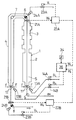
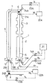
以下図1〜図3に示す第1例により、請求項1記載の発明の実施の形態を説明する。図1において1は、ステンレス鋼帯から成るストリップSをN2雰囲気中で光輝焼鈍する竪型の連続熱処理炉で、2はその加熱帯、3は冷却帯、4は保護筒である。ストリップSは、炉外の転向ロール5、炉内のステアリングロール6と転向ロール7、炉外のステアリングロール8に、順次巻掛けられて走行する。
【0010】
炉の入口部と出口部には炉内雰囲気シール用に、前述の図10と同じくシリコンゴムなどの各種ゴムあるいは繊維布等の弾性材を表面にコーティングしたシールロール11およびシールロール12が設けてある。これらのシールロール駆動用の空圧シリンダ13A,13Bは、圧力切替弁14A,14Bを介して図示しない空気圧供給源に接続され、この圧力切替弁による供給圧力の切替えによって、ストリップSの両面に押付けられるシールロールの挟圧力Fを切替調節するようになっている。空圧シリンダ13A,13Bによるシールロールの駆動機構や、シールロールの外周面や端面と炉体との間のシール機構等は、たとえば特開平10ー46261号公報に開示のものなど、公知のものを使用することができる。
【0011】
ステアリングロール6,8の近傍部には、蛇行量検出器21A,21Bがそれぞれ設けられ、これらの検出器は、たとえばライン状の投光器と、複数の受光素子を直線状に配列した受光器を、ストリップSの縁部をストリップ両面側から挟む形で配置して成る。そしてこれらの検出器により電気的に検出されたストリップSの蛇行量検出値W1,W2が、予め設定した所定の閾値α(たとえば5mm)を越えたとき、蛇行制御装置22A,22Bはサーボ弁23A,23Bにそれぞれ、ステアリング作動信号V1,V2を出力し、蛇行量および蛇行方向に応じて油圧シリンダ24A,24Bに圧油を供給して、ステアリングロール6,8をそれぞれ蛇行量減少方向に傾動駆動、あるいはさらに軸方向(板巾方向)へ進退駆動して、蛇行修正をおこなうものである。これらの制御機器および制御方法、ステアリングロールの駆動機構等は、たとえば特開平6ー316357号公報に開示のものなど、公知のものを使用することができる。
【0012】
31,32は、加熱帯2および保護筒4部に設けた炉内圧検出用の炉圧検出器で、これら検出器による炉圧検出値P1,P2は、挟圧制御装置33に入力される。挟圧制御装置33は、蛇行量設定器34の閾値βおよび炉圧設定器35の炉圧許容下限値PL と、前記蛇行量検出値W1,W2および炉圧検出値P1,P2とを対比して、下記のようにしてシールロール11,12の挟圧力Fを制御する。なおシールロール11とシールロール12は、独立して挟圧力を制御されるものであり、以下シールロール11についてその制御方法を、図2および図3を参照して説明する。なお図3においては、信号V,R等の添字1,2は省略してあり、以下他の例も同様とする。
【0013】
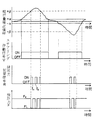
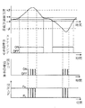
すなわち、シールロール11および12により所定の設定挟圧力F0でストリップSを挟圧しつつ、ストリップSを走行させて連続熱処理炉1内で光輝焼鈍処理を施す。処理中にストリップSが蛇行して、蛇行量検出器21AによるストリップSの蛇行量検出値W1が、図3に示すように蛇行修正用の閾値αを越えると、蛇行制御装置22Aはステアリング作動信号V1を発して空圧シリンダ13Aによりステアリングロール6を駆動して蛇行の修正をおこなう。
【0014】
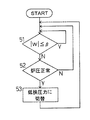
上記の蛇行量検出値W1は、挟圧制御装置33においても閾値β(たとえば50mm)と比較され(図2におけるステップ51)、蛇行量検出値W1が閾値βを越えたら、炉圧検出器31による炉圧検出値P1と炉圧許容下限値PL とを比較し(ステップ52)、炉圧がこの下限値PL を越えていれば挟圧力切替信号R1を発して圧力切替弁14Aを作動させ、空圧シリンダ13Aによるシールロール11の挟圧力Fを所定の低挟圧力FL (この例ではFL =0)に切替える(ステップ53)。
【0015】
その後もストリップの蛇行量検出値W1と炉圧検出値P1の監視を続け、挟圧力Fの切替えによるロール間のすきまG(図10参照)の拡大により、炉圧が炉圧許容下限値PL 以下となった時点t1(図3参照)で、炉圧が正常範囲以下となったと判断し(ステップ52)、挟圧制御装置33は挟圧力切替信号R1の出力を停止する。これによって圧力切替弁14Aは初期の状態に復帰して空圧シリンダ13Aによるシールロール11の挟圧力は初期の設定挟圧力F0に戻され、シールロール11,11間のすきまは減少し、このすきま部からの雰囲気ガスの漏出量が減少して、炉圧は上昇方向に転じる。
【0016】
この炉圧上昇により、炉圧が炉圧許容下限値PL を越えた時点t2(図3参照)で、炉圧は正常範囲と判断して、再度挟圧力切替信号R1の出力により前記と同様にしてシールロール11の設定挟圧力F0を低挟圧力FL に切替え、以下同様な挟圧力の制御を、蛇行量検出値W1が閾値β以下となる迄繰返すのである。なおこの低挟圧力FL への切替えは、炉圧検出値P1=(炉圧許容下限値PL +所定の小圧力値)となった時点でおこなうのが、ハンティング防止のため好ましい。
【0017】
そして蛇行量検出値W1が閾値α以下となれば、ステアリングロール6による蛇行修正は終了し、ストリップSが上記と反対方向に蛇行した場合も、図3の右半部に図示するように、上記と同様な挟圧力の制御がおこなわれ、また前記したようにシールロール12についても、シールロール11とは独立して蛇行量検出器21Bによる蛇行量検出値W2に基づいて、蛇行制御装置22Bによる蛇行修正中に、上記と同様な挟圧力の制御がおこなわれるものであり、これらの点は後述の他の例においても同様である。
【0018】
このようにステアリングロール6,8による蛇行修正中に、蛇行量が所定の閾値βを越えたとき、シールロール11,12による挟圧力Fを低挟圧力FL に切替え、炉圧が許容下限値以下となったとき挟圧力Fを当初の設定挟圧力F0に戻すようにしたので、シールロール11,12によるストリップの巾方向の拘束が間欠的にゆるめられて、ストリップSはステアリングロール6,8による蛇行修正力を受けつつ過度の拘束のない、より自然なパスラインに沿って走行することになるので、シールロール11,12がステアリングロール6による蛇行修正を阻害することがなく、またシールロール11,12がストリップSの蛇行をひきおこすということもなくなるのである。
【0019】
また挟圧力Fは、間欠的に低挟圧力FL に切替えられている期間を除いて、設定挟圧力F0に維持されシールロールのすきまを少量に維持するので、炉内の雰囲気ガスが連続的に大量に漏出することはなく、シールロール11,12によるシール性は良好に維持されるのである。
【0020】
またこの例では、炉圧を直接検出して該炉圧が許容下限値以下となったとき挟圧力を設定挟圧力に戻すので、炉内雰囲気ガスの漏出が過大となったりあるいはさらに外気が炉内へ侵入するのを、確実に防ぐことができる。
【0021】
次に図4〜図6に示す第2例により、請求項2記載の発明の実施の形態を説明する。図4に示す装置は、図1における炉圧検出器31,32、および炉圧設定器35を除去し、挟圧制御装置36を図1のものとは異なる制御をおこなうものとした点を除いては、図1と同構成を有するものであるので、図1と同一部分には同一符号を付してそれらの詳細な説明(動作を含む)は省略する。
【0022】
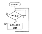
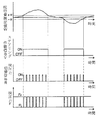
この例においては、ストリップSの光輝焼鈍処理中に、第1例と同様にステアリングロール6,8により蛇行修正がおこなわれ、蛇行量検出器21A(21B)[注:シールロール12関係分をカッコ書きで記す]による蛇行量検出値W1(W2)は、挟圧制御装置36においても閾値βと比較され(図5におけるステップ61)、蛇行量検出値W1(W2)が閾値βを越えたら、挟圧制御装置36は内蔵するタイマ回路により、所定の時間間隔T(たとえば30秒)で、所定の保持時間t(たとえば1秒間)の間、挟圧力切替信号R1(R2)を出力して第1例と同様にシールロール11(12)の挟圧力Fを低挟圧力FL に切替え(ステップ62)、これを蛇行量検出値W1(W2)が閾値β以下となる迄繰返す。
【0023】
これによって、蛇行量検出値W1(W2)が閾値βを越えている間、シールロール11(12)の挟圧力Fを設定挟圧力F0から低挟圧力FL に切替えて、保持時間tの後に設定挟圧力F0に戻すという、挟圧力Fの低減・増加操作が時間間隔Tで繰返される。なお上記の保持時間tおよび時間間隔Tの値は、炉圧の過度の低下あるいは雰囲気ガスの過大漏出などを生じないように、実炉による試行運転などにより選定する。
【0024】
このようにステアリングロール6,8による蛇行修正中に、シールロール11,12による挟圧力を間欠的に低挟圧力に切替えるようにしたので、シールロール11,12によるストリップの巾方向の拘束が間欠的にゆるめられて、前記第1例と同様に、シールロール11,12がステアリングロール6,8による蛇行修正を阻害することがなく、またシールロール11,12がストリップの蛇行をひきおこすこともなく、またシールロール11,12によるシール性も良好に維持されるという作用効果が得られるのである。
【0025】
またこの例では、炉圧を制御因子として用いないので、第1例における炉圧検出器31,32や炉圧設定器35は不要となり、挟圧制御装置36も簡潔化されるので、制御装置が第1例よりも低コストのものですむ。
【0026】
なおこの例においては、挟圧力切替えのための蛇行量の閾値βを、ステアリングロールによる蛇行修正のための閾値αより大としたが、図7に示すように、上記閾値βを閾値αと同値とし、ステアリングロールによる蛇行修正の全期間にわたって、挟圧力の切替をおこなうようにしてもよく、この場合は早期から挟圧力の切替えをこなうことにより、蛇行の修正効果が大きくなり、最大蛇行量を小さく抑えることができる。
【0027】
またこれと同様に、前記第1例においても、閾値βを閾値αと同値として蛇行修正の全期間にわたって挟圧力の切替えをこなうようにしてもよく、これによって上記と同様に最大蛇行量を小さく抑えることができる。
【0028】
次に図8および図9に示す第3例により、請求項3記載の発明の実施の形態を説明する。図8に示す装置は、図4における蛇行量設定器34を省略し、蛇行量検出器21A,21Bの蛇行量検出値W1,W2は蛇行制御装置22A,22Bのみに入力するものとし、挟圧制御装置37は図4のものとは異なる制御をおこなうものとした点を除いては、図4と同構成を有するものであるので、図4と同一部分には図4と同一符号を付してそれらの詳細な説明(動作も含む)は省略する。
【0029】
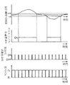
この例においては、ストリップSの光輝焼鈍処理中に、第1例と同様にステアリングロール6,8により蛇行修正がおこなわれるが、挟圧制御装置37は、上記のステアリングロール6,8による蛇行修正とは無関係に、ストリップSの走行中(光輝焼鈍処理中)の全期間にわたって、所定の時間間隔T(たとえば30秒)で、所定の保持時間t(たとえば1秒間)の間、挟圧力切替信号R1,R2を出力することを繰返す。
【0030】
これによって、シールロール11,12の挟圧力Fを、低挟圧力FL に切替えたのち、保持時間t後に設定挟圧力F0に戻すという、挟圧力Fの低減・増加操作が時間間隔Tで繰返される。なお上記の保持時間tおよび時間間隔Tの値は、前記第2例と同様にして選定する。
【0031】
このようにストリップSの走行中に、蛇行修正とは関係なく、シールロール11,12による挟圧力を間欠的に低挟圧力に切替えるようにしたので、シールロール11,12によるストリップの巾方向の拘束が間欠的にゆるめられて、前記第1例と同様に、シールロール11,12がステアリングロール6,8による蛇行修正を阻害することがなく、またシールロール11,12がストリップの蛇行をひきおこすこともなく、またシールロール11,12によるシール性も良好に維持されるという作用効果が得られるのである。
【0032】
またこの例では、ストリップの蛇行量を制御因子として用いないので、第2例における蛇行量設定器34も不要となり、挟圧制御装置37はタイマ機能を有する一層簡潔なものですみ、制御装置は第2例よりもさらに低コストのものですむ。
【0033】
この発明は上記各例に限定されるものではなく、たとえば低挟圧力FL の値は0以外の値としてもよく、またストリップの蛇行量の検出は、ステアリングロール用のものとは別に設けた蛇行量検出器で行なってもよい。またこの発明は、ストリップに対して光輝焼鈍以外の処理をおこなう連続処理炉や、ストリップが横方向に走行する横型連続処理炉におけるシールロールの挟圧力制御にも適用できるものである。
【0034】
【発明の効果】
以上説明したようにこの発明によれば、シールロールによるストリップの挟圧力が間欠的に低挟圧力に切替えられストリップの巾方向の拘束が間欠的にゆるめられるので、ストリップは過度の拘束のない、より自然なパスラインに沿って走行し、シールロールがステアリングロールによる蛇行修正を阻害することがなく、またシールロールがストリップの蛇行をひきおこすということもなくなる。またシールロールによるストリップの挟圧力は、低挟圧力に切替えられている間を除いて所定の設定挟圧力に維持されるので、炉内の雰囲気ガスが連続的に大量に漏出することはなく、シールロールによるシール性は良好に維持される。
【0035】
また上記の効果に加えて、請求項1記載の発明によれば、炉内雰囲気ガスの漏れが過大となったり外気が炉内に侵入するのを確実に防止でき、また請求項2記載の発明によれば、制御装置は簡潔化され低コストのものですみ、また請求項3記載の発明によれば、制御装置はさらに簡潔化され低コストのものですむ。
【図面の簡単な説明】
【図1】この発明の実施の形態の第1例を示す機器系統図である。
【図2】図1の装置による制御手順を示すフローチャートである。
【図3】図1の装置による制御方法を示す動作線図である。
【図4】この発明の実施の形態の第2例を示す機器系統図である。
【図5】図4の装置による制御手順を示すフローチャートである。
【図6】図4の装置による制御方法を示す動作線図である。
【図7】図4の装置による制御方法の他の実施態様を示す図6相当図である。
【図8】この発明の実施の形態の第3例を示す機器系統図である。
【図9】図8の装置による制御方法を示す動作線図である。
【図10】シールロールによるストリップ挟圧状態を示す模式説明図である。
【符号の説明】
1…連続熱処理炉、6…ステアリングロール、8…ステアリングロール、11…シールロール、12…シールロール、13A…空圧シリンダ、13B…空圧シリンダ、14A…圧力切替弁、14B…圧力切替弁、21A…蛇行量検出器、21B…蛇行量検出器、31…炉圧検出器、32…炉圧検出器、33…挟圧制御装置、34…蛇行量設定器、35…炉圧設定器、36…挟圧制御装置、37…挟圧制御装置。[0001]
BACKGROUND OF THE INVENTION
The present invention relates to a method for controlling the clamping pressure of a seal roll provided for maintaining the atmosphere in the furnace in a continuous strip processing furnace.
[0002]
[Prior art]
For example, in a continuous processing furnace that performs bright annealing or non-oxidation annealing of a strip, in order to maintain the inside of the furnace in a non-oxidizing atmosphere, a seal roll that sandwiches and seals the strip at the inlet and outlet of the furnace is provided. FIG. 10 shows an example, in which the strip S is clamped by a pair of
[0003]
On the other hand, in the above-mentioned continuous processing furnace, a strip running at a high speed has a meandering state in which it is displaced in the plate width direction. Therefore, in order to correct this meander, the strip is wound around the furnace or in the vicinity of the outside of the furnace. A steering roll that tilts the roll to keep the amount of meandering to a small amount is provided, but if the strip clamping force F by the seal roll is large, the meandering correction by the steering roll is hindered and the amount of meandering becomes excessive. Rolls can cause meandering. Therefore, in order to ensure the correction of meandering, the clamping pressure F has to be reduced, and there is a problem that the amount of leakage of the atmospheric gas in the furnace becomes large and the outside air enters the furnace.
[0004]
[Problems to be solved by the invention]
SUMMARY OF THE INVENTION The present invention is intended to solve the above-mentioned conventional problems, and provides a method for controlling the sandwiching pressure of a seal roll in a continuous strip processing furnace capable of maintaining good sealing performance with a seal roll without hindering meandering correction with a steering roll. The purpose is to do.
[0005]
[Means for Solving the Problems]
In order to achieve the above object, a method for controlling the clamping pressure of a seal roll in a continuous strip processing furnace according to
[0006]
According to a second aspect of the present invention, there is provided a method for controlling the clamping pressure of a seal roll in a continuous strip processing furnace, including a steering roll for correcting the meandering of the strip, and covering the both sides of the strip with a surface portion coated with an elastic material at the entrance and exit of the furnace In a continuous strip processing furnace equipped with a seal roll that is clamped at a predetermined set clamping pressure, the amount of meandering of the running strip is detected, and when the meandering amount detection value exceeds a predetermined threshold, the strip of the strip by the seal roll is detected. The pinching pressure is switched to a predetermined low pinching pressure, and is returned to the set pinching pressure after a predetermined holding time from the switching time. It repeats until it becomes below a threshold value, and when the said meandering amount detection value becomes below the said threshold value, the said clamping pressure is returned to the said setting clamping pressure, It is characterized by the above-mentioned.
[0007]
According to a third aspect of the present invention, there is provided a method for controlling the clamping pressure of a seal roll in a continuous strip processing furnace, including a steering roll for correcting the meandering of the strip, and covering the both sides of the strip with a surface portion coated with an elastic material at the entrance and exit of the furnace In a continuous strip processing furnace equipped with a seal roll that clamps at a predetermined set clamping pressure, the strip setting pressure is switched to a predetermined low clamping pressure while the strip is running, and the setting is performed after a predetermined holding time. The reduction / increase operation of the clamping pressure, which is returned to the clamping pressure, is repeated at predetermined time intervals.
[0008]
According to the means of
[0009]
DETAILED DESCRIPTION OF THE INVENTION
An embodiment of the invention described in
[0010]
At the entrance and exit of the furnace, there are provided a seal roll 11 and a
[0011]
In the vicinity of the
[0012]
31 and 32 are furnace pressure detectors for detecting the furnace pressure provided in the
[0013]
That is, while the strip S is clamped by the
[0014]
Meandering amount detection value W 1 of the above (
[0015]
Thereafter, the strip meandering detection value W 1 and the furnace pressure detection value P 1 are continuously monitored, and the gap G between the rolls (see FIG. 10) is increased by switching the clamping pressure F, so that the furnace pressure becomes the allowable lower limit of the furnace pressure. At time t 1 (see FIG. 3) when the pressure is equal to or lower than PL, it is determined that the furnace pressure is equal to or lower than the normal range (step 52), and the clamping
[0016]
At time t 2 (see FIG. 3) when the furnace pressure exceeds the allowable furnace pressure lower limit value PL due to this furnace pressure increase, the furnace pressure is determined to be in the normal range, and the above-described operation is performed again by the output of the clamping pressure switching signal R 1. It switches the setting clamping force F 0 of the sealing rolls 11 to Teikyo pressure FL Similarly, the following control similar clamping force is to repeat until meandering amount detection value W 1 is equal to or less than the threshold value beta. The switching to the low clamping pressure FL is preferably performed at the time when the detected furnace pressure value P 1 = (furnace pressure allowable lower limit value PL + predetermined small pressure value) to prevent hunting.
[0017]
And if meandering amount detection value W 1 is equal to or less than the threshold value alpha, as meandering correction by steering
[0018]
As described above, when the meandering amount exceeds the predetermined threshold β during the meandering correction by the steering rolls 6 and 8, the clamping pressure F by the seal rolls 11 and 12 is switched to the low clamping pressure FL, and the furnace pressure is less than the allowable lower limit value. since then returned to clamping force F to the original set clamping pressure F 0 when a restraint of the width direction of the strip is loosened intermittently by the sealing rolls 11 and 12, the strip S is steering
[0019]
Further, the holding pressure F is maintained at the set holding pressure F 0 except for the period when it is intermittently switched to the low holding pressure FL, and the clearance of the seal roll is kept small. Therefore, the sealing performance by the seal rolls 11 and 12 is maintained well.
[0020]
In this example, since the furnace pressure is directly detected and the holding pressure is returned to the set holding pressure when the furnace pressure falls below the allowable lower limit value, the leakage of the atmosphere gas in the furnace becomes excessive, or the outside air further flows into the furnace. It is possible to reliably prevent intrusion.
[0021]
Next, an embodiment of the invention described in
[0022]
In this example, during the bright annealing process of the strip S, the meandering correction is performed by the steering rolls 6 and 8 in the same manner as in the first example, and the
[0023]
As a result, while the meandering amount detection value W 1 (W 2 ) exceeds the threshold value β, the holding pressure F of the seal roll 11 (12) is switched from the set holding pressure F 0 to the low holding pressure FL, and the holding time t of returning the setting clamping force F 0 after reduction, increase operation the clamping pressure F is repeated at time intervals T. The values of the holding time t and the time interval T are selected by trial operation using an actual furnace so as not to cause an excessive decrease in the furnace pressure or excessive leakage of atmospheric gas.
[0024]
As described above, during the meandering correction by the steering rolls 6 and 8, the clamping pressure by the seal rolls 11 and 12 is intermittently switched to a low clamping pressure, so that the strip width constraint by the sealing rolls 11 and 12 is intermittent. As in the first example, the seal rolls 11 and 12 do not obstruct the meandering correction by the steering rolls 6 and 8, and the seal rolls 11 and 12 do not cause the meandering of the strip. Moreover, the effect that the sealing performance by the seal rolls 11 and 12 is maintained well can be obtained.
[0025]
In this example, since the furnace pressure is not used as a control factor, the
[0026]
In this example, the threshold value β of the meandering amount for switching the clamping pressure is made larger than the threshold value α for correcting meandering by the steering roll. However, as shown in FIG. 7, the threshold value β is equal to the threshold value α. The pinching pressure may be switched over the entire period of correction of the meandering by the steering roll. In this case, the effect of correcting the meandering is increased by switching the pinching pressure from an early stage, and the maximum meandering The amount can be kept small.
[0027]
Similarly, in the first example, the threshold value β may be the same as the threshold value α, and the pinching pressure may be switched over the entire meandering correction period. Can be kept small.
[0028]
Next, the third embodiment shown in FIGS. 8 and 9 will be used to explain the third embodiment of the present invention. The apparatus shown in FIG. 8 omits the meandering
[0029]
In this example, during the bright annealing process of the strip S, meandering correction is performed by the steering rolls 6 and 8 as in the first example, but the pinching
[0030]
As a result, after the holding pressure F of the seal rolls 11 and 12 is switched to the low holding pressure FL, the reduction / increase operation of the holding pressure F is repeated at the time interval T to return to the set holding pressure F 0 after the holding time t. It is. Note that the values of the holding time t and the time interval T are selected in the same manner as in the second example.
[0031]
In this way, during the running of the strip S, the clamping pressure by the seal rolls 11 and 12 is intermittently switched to a low clamping pressure regardless of the meandering correction. The restraint is loosened intermittently, and the seal rolls 11 and 12 do not hinder the meandering correction by the steering rolls 6 and 8, and the seal rolls 11 and 12 cause the meandering of the strip as in the first example. In addition, there is an effect that the sealability by the seal rolls 11 and 12 is maintained well.
[0032]
In this example, since the meandering amount of the strip is not used as a control factor, the meandering
[0033]
The present invention is not limited to the above examples. For example, the value of the low clamping pressure FL may be a value other than 0, and the detection of the amount of meandering of the strip is performed separately from that for the steering roll. You may carry out with a quantity detector. The present invention can also be applied to the control of the sandwiching pressure of the seal roll in a continuous processing furnace that performs processing other than bright annealing on the strip and a horizontal continuous processing furnace in which the strip travels in the horizontal direction.
[0034]
【The invention's effect】
As described above, according to the present invention, since the clamping pressure of the strip by the seal roll is intermittently switched to a low clamping pressure and the constraint in the width direction of the strip is intermittently loosened, the strip is not excessively restrained. It travels along a more natural path line, the seal roll does not hinder the meandering correction by the steering roll, and the seal roll does not cause the meander of the strip. Further, the sandwiching pressure of the strip by the seal roll is maintained at a predetermined set sandwiching pressure except when it is switched to a low sandwiching pressure, so that the atmosphere gas in the furnace does not continuously leak in large quantities, The sealing performance by the seal roll is maintained well.
[0035]
In addition to the above effects, according to the first aspect of the invention, it is possible to reliably prevent the leakage of the atmosphere gas in the furnace from being excessive or the outside air from entering the furnace, and the invention according to the second aspect. Therefore, the control device can be simplified and reduced in cost, and according to the invention of
[Brief description of the drawings]
FIG. 1 is a device system diagram showing a first example of an embodiment of the present invention;
FIG. 2 is a flowchart showing a control procedure by the apparatus of FIG.
FIG. 3 is an operation diagram showing a control method by the apparatus of FIG. 1;
FIG. 4 is a device system diagram showing a second example of the embodiment of the present invention.
FIG. 5 is a flowchart showing a control procedure by the apparatus of FIG. 4;
6 is an operation diagram showing a control method by the apparatus of FIG. 4; FIG.
7 is a view corresponding to FIG. 6 showing another embodiment of the control method by the apparatus of FIG. 4;
FIG. 8 is an equipment system diagram showing a third example of the embodiment of the invention.
FIG. 9 is an operation diagram showing a control method by the apparatus of FIG.
FIG. 10 is a schematic explanatory view showing a state of strip clamping by a seal roll.
[Explanation of symbols]
DESCRIPTION OF
Claims (3)
Priority Applications (1)
| Application Number | Priority Date | Filing Date | Title |
|---|---|---|---|
| JP2000389159A JP4635337B2 (en) | 2000-12-21 | 2000-12-21 | Control method of clamping pressure of seal roll in continuous strip processing furnace |
Applications Claiming Priority (1)
| Application Number | Priority Date | Filing Date | Title |
|---|---|---|---|
| JP2000389159A JP4635337B2 (en) | 2000-12-21 | 2000-12-21 | Control method of clamping pressure of seal roll in continuous strip processing furnace |
Publications (2)
| Publication Number | Publication Date |
|---|---|
| JP2002194446A JP2002194446A (en) | 2002-07-10 |
| JP4635337B2 true JP4635337B2 (en) | 2011-02-23 |
Family
ID=18855768
Family Applications (1)
| Application Number | Title | Priority Date | Filing Date |
|---|---|---|---|
| JP2000389159A Expired - Fee Related JP4635337B2 (en) | 2000-12-21 | 2000-12-21 | Control method of clamping pressure of seal roll in continuous strip processing furnace |
Country Status (1)
| Country | Link |
|---|---|
| JP (1) | JP4635337B2 (en) |
Family Cites Families (2)
| Publication number | Priority date | Publication date | Assignee | Title |
|---|---|---|---|---|
| JPH06184648A (en) * | 1992-12-21 | 1994-07-05 | Kawasaki Steel Corp | Entrance / exit sealing device for annealing furnace |
| JPH10280053A (en) * | 1997-04-04 | 1998-10-20 | Sumitomo Metal Ind Ltd | Sealing equipment for continuous annealing furnace |
-
2000
- 2000-12-21 JP JP2000389159A patent/JP4635337B2/en not_active Expired - Fee Related
Also Published As
| Publication number | Publication date |
|---|---|
| JP2002194446A (en) | 2002-07-10 |
Similar Documents
| Publication | Publication Date | Title |
|---|---|---|
| AU3616500A (en) | Method and apparatus for detecting and quantifying seal leaks in installed emergency shut down or other valves, during production and during shutdown | |
| JP4635337B2 (en) | Control method of clamping pressure of seal roll in continuous strip processing furnace | |
| JP3931619B2 (en) | Combustion device control method | |
| JP4574051B2 (en) | Heat treatment method and heat treatment apparatus used therefor | |
| KR950704061A (en) | SNAKING CONTROL METHOD AND TANDEM PLATE ROLLING MILL FACILITY LINE | |
| JPH05304099A (en) | Flow-rate control device | |
| JP3499042B2 (en) | Atmospheric gas leakage prevention device for continuous annealing furnace | |
| KR100502851B1 (en) | Sealing apparatus in bright annealing furnace | |
| WO2022230766A1 (en) | Gas processing system | |
| JP2022170680A (en) | Gas processing system | |
| JPS62130956A (en) | Method for preventing meandering of metal strips | |
| JP2709246B2 (en) | Meandering prevention control method for strip heat treatment equipment | |
| JP3426031B2 (en) | Sealing device for compartment entrance and exit of heat treatment furnace using atmosphere gas containing hydrogen gas | |
| JPH07260255A (en) | Hot water supply equipment | |
| JPS61226213A (en) | Trimming method of strip steel | |
| JP2505055Y2 (en) | Vacuum furnace | |
| JPH03253518A (en) | Sealing method for atmosphere treatment of band-shaped material | |
| JPH10202075A (en) | Method of maintaining permeability of hydrophobic permeation membrane | |
| JPH04325632A (en) | Method and device for maintaining furnace pressure in continuous annealing furnace | |
| US4963090A (en) | Reverse flow furnace/retort system | |
| JPH05255760A (en) | Device for controlling tension in vertical type annealing furnace | |
| JPH10202071A (en) | Method for recovering permeation performance of hydrophobic permeation membrane | |
| SU722963A1 (en) | Continuous furnace gas lock | |
| JPH08225856A (en) | Control of meandering of strip | |
| JPS62247033A (en) | Centering device for floating heat treatment furnace |
Legal Events
| Date | Code | Title | Description |
|---|---|---|---|
| A621 | Written request for application examination |
Free format text: JAPANESE INTERMEDIATE CODE: A621 Effective date: 20071031 |
|
| RD04 | Notification of resignation of power of attorney |
Free format text: JAPANESE INTERMEDIATE CODE: A7424 Effective date: 20100715 |
|
| A977 | Report on retrieval |
Free format text: JAPANESE INTERMEDIATE CODE: A971007 Effective date: 20101019 |
|
| TRDD | Decision of grant or rejection written | ||
| A01 | Written decision to grant a patent or to grant a registration (utility model) |
Free format text: JAPANESE INTERMEDIATE CODE: A01 Effective date: 20101026 |
|
| A01 | Written decision to grant a patent or to grant a registration (utility model) |
Free format text: JAPANESE INTERMEDIATE CODE: A01 |
|
| A61 | First payment of annual fees (during grant procedure) |
Free format text: JAPANESE INTERMEDIATE CODE: A61 Effective date: 20101108 |
|
| FPAY | Renewal fee payment (event date is renewal date of database) |
Free format text: PAYMENT UNTIL: 20131203 Year of fee payment: 3 |
|
| R150 | Certificate of patent or registration of utility model |
Ref document number: 4635337 Country of ref document: JP Free format text: JAPANESE INTERMEDIATE CODE: R150 Free format text: JAPANESE INTERMEDIATE CODE: R150 |
|
| LAPS | Cancellation because of no payment of annual fees |