JP4635206B2 - Method for surface modification or cleaning inside tube, and device for surface modification or cleaning inside tube used in the method - Google Patents
Method for surface modification or cleaning inside tube, and device for surface modification or cleaning inside tube used in the method Download PDFInfo
- Publication number
- JP4635206B2 JP4635206B2 JP2006055970A JP2006055970A JP4635206B2 JP 4635206 B2 JP4635206 B2 JP 4635206B2 JP 2006055970 A JP2006055970 A JP 2006055970A JP 2006055970 A JP2006055970 A JP 2006055970A JP 4635206 B2 JP4635206 B2 JP 4635206B2
- Authority
- JP
- Japan
- Prior art keywords
- tube
- pressure
- pipe
- cavitation
- nozzle
- Prior art date
- Legal status (The legal status is an assumption and is not a legal conclusion. Google has not performed a legal analysis and makes no representation as to the accuracy of the status listed.)
- Active
Links
Images


Landscapes
- Cleaning By Liquid Or Steam (AREA)
- Cleaning In General (AREA)
Description
本発明は,管を有する機械部品や構造物などで,管内面にピーニングを実施して圧縮残留応力を導入して,原子力プラントの配管などの応力腐食割れを防止したり,エンジンのコモンレール式燃料噴射装置におけるコモンレール、車両に使用される中空スタビライザ、中空トーションバーなどの疲労強度を向上したり,あるいは交差穴を有する機械部品などのバリ取りを行う等、管内部の表面を改質したり、あるいは、熱交換器などの管内部の表面を洗浄する等の、管内部の表面改質または洗浄方法及び該方法に使用される管内部の表面改質または洗浄装置に関する。 The present invention is intended to prevent stress corrosion cracking in piping of nuclear power plants, etc. by peening the inner surface of pipes for machine parts and structures having pipes, and to prevent the occurrence of stress corrosion cracking in piping of nuclear power plants. Improving the fatigue strength of common rails in injection devices, hollow stabilizers used in vehicles, hollow torsion bars, etc., or deburring machine parts with cross holes, etc. Alternatively, the present invention relates to a method for surface modification or cleaning inside a tube, such as cleaning a surface inside a tube such as a heat exchanger, and a surface modification or cleaning device inside a tube used in the method.
従来から管内部の表面を改質する(ピーニング)方法としては、エア式ショットピーニングがある(例えば、特許文献1、2参照)。
この方法は、ショットと呼ばれる微細な球を高圧空気によって加速し、ノズルと呼ばれる噴き出し口から処理対象部品に高速で吹き付けることにより、対象部品表面に残留圧縮応力を付加するものである。
しかしながら、この方法では、管内部を有効に処理するには構造が複雑になるという問題があった。
Conventionally, as a method for modifying (peening) the surface inside the pipe, there is air-type shot peening (see, for example,
In this method, a fine sphere called a shot is accelerated by high-pressure air, and a residual compressive stress is applied to the surface of the target part by spraying it on the part to be processed at a high speed from an outlet called a nozzle.
However, this method has a problem that the structure is complicated in order to effectively process the inside of the pipe.
一方、ショットを用いない管内部のピーニング方法としては、ウォータージェットピーニングがある(例えば、特許文献3、4参照)。
この方法は、液中にてノズルから噴射するキャビテーションを伴う高速水噴流を金属材料表面に直接衝突させてキャビテーション気泡を崩壊させ、その衝撃圧で金属材料表面部の残留応力を解放するものである。
On the other hand, there is water jet peening as a peening method inside the pipe without using a shot (see, for example,
In this method, a high-speed water jet accompanied by cavitation ejected from a nozzle in the liquid is directly collided with the surface of the metal material to collapse the cavitation bubbles, and the residual stress on the surface of the metal material is released by the impact pressure. .
キャビテーションは、一般にポンプなどの流体機械の表面を壊食するなど悪影響を与える現象として知られているが、その一方で、キャビテーションの崩壊衝撃力は、ショットピーニングのごとく、金属材料の表面改質による高強度化に有効利用することができ、近年では部品洗浄の分野にも利用されている。 Cavitation is generally known as an adverse effect such as eroding the surface of a fluid machine such as a pump. It can be effectively used to increase the strength, and in recent years, it is also used in the field of parts cleaning.
これまでに,管内部の圧力を変化させるとキャビテーション気泡の崩壊領域、すなわちピーニング領域が変化し,キャビテーション噴流の噴射圧力p1と管内部の圧力p2の圧力の比であるキャビテーション数κにより,同一の管内径の場合には,キャビテーション数κによりピーニング領域を制御できることが判明していた(非特許文献1参照)。
しかしながら,管の内径が異なると,どの領域がピーニングできるか全く不明であるという課題がある。
So far, when the pressure inside the tube is changed, the collapse region of the cavitation bubble, that is, the peening region, changes, and the same cavitation number κ, which is the ratio of the injection pressure p1 of the cavitation jet and the pressure p2 inside the tube, In the case of the inner diameter of the tube, it has been found that the peening region can be controlled by the cavitation number κ (see Non-Patent Document 1).
However, when the inner diameter of the tube is different, there is a problem that it is completely unknown which region can be peened.
本発明の課題は、管の内径が異なっても、キャビテーション気泡の崩壊領域を制御することができる管内部の表面改質または洗浄方法及び該方法に使用される管内部の表面改質または洗浄装置を提供することである。 An object of the present invention is to provide a surface reforming or cleaning method for the inside of a tube and a surface reforming or cleaning device for the inside of the tube used in the method, which can control the collapse region of cavitation bubbles even if the inner diameters of the tubes are different. Is to provide.
上記課題を達成するために、本発明の管内部の表面改質または洗浄方法は、ノズルから高圧液体を管の内部に噴射して、高圧液体の噴流まわりにキャビテーションを発生させ、キャビテーション気泡の崩壊衝撃力により管内部の表面を改質または洗浄する方法であって、前記管内径と前記ノズル口径に応じて、前記高圧液体の噴射圧力と前記管内部の圧力を制御することにより前記管内部のキャビテーション気泡の崩壊領域を制御する管内部の表面改質または洗浄方法において、前記管内径D,前記ノズル口径d,前記高圧液体の噴射圧力p1,前記管内部圧力p2,前記崩壊領域xとした場合、以下の関係式が成立することを特徴とする。

本発明の管内部の表面改質または洗浄方法は、前記ノズルを前記管外部に配置して、前記管内部を液体で充満するとともに、前記高圧液体を液体中に噴射することを特徴とする。
キャビテーションは,沸騰と同様に液体が気体になる現象である。ただし,キャビテーションの場合は,流速が増大して,圧力が飽和蒸気圧まで低下して気体になる。速度が低下して圧力が回復するときに,短時間に気泡が収縮してマイクロジェットや衝撃波(収縮後の再膨張による)を生じて衝撃力が発生する。キャビテーションの場合にも,沸騰と同様に,小さな気泡(通常,水中に8ppm程度空気が溶けている)からキャビテーションになるので,大きな気泡からキャビテーションになると,大きなキャビテーション気泡になる。しかし,収縮時に小さくなれないので,衝撃力が気泡の再膨張により緩慢になり,衝撃力が極端に弱まる。この気体により衝撃力が弱まることをクッション効果と呼ぶ。
したがって、上記の本発明の方法によれば、クッション効果によるキャビテーション衝撃力が弱まることはない。
The surface modification or cleaning method for the inside of a pipe according to the present invention is characterized in that the nozzle is disposed outside the pipe, the inside of the pipe is filled with a liquid, and the high-pressure liquid is injected into the liquid.
Cavitation is a phenomenon in which a liquid becomes a gas, similar to boiling. However, in the case of cavitation, the flow rate increases and the pressure decreases to the saturated vapor pressure to become a gas. When the pressure decreases and the pressure recovers, the bubbles contract in a short period of time, creating a microjet or shock wave (due to re-expansion after contraction), generating an impact force. Also in the case of cavitation, as with boiling, cavitation starts from small bubbles (usually about 8 ppm of air is dissolved in water), so when cavitation starts from large bubbles, it becomes large cavitation bubbles. However, since it cannot be reduced during contraction, the impact force becomes sluggish due to the re-expansion of the bubbles, and the impact force becomes extremely weak. That the impact force is weakened by this gas is called a cushion effect.
Therefore, according to the method of the present invention described above, the cavitation impact force due to the cushion effect is not weakened.
本発明の管内部の表面改質または洗浄方法は、前記液体が水であることを特徴とする。
これによれば、本発明の方法を安価に実施することができる。
The surface modification or cleaning method for the inside of a tube according to the present invention is characterized in that the liquid is water.
According to this, the method of this invention can be implemented at low cost.
本発明の管は、上記管内部の表面改質または洗浄方法で製造されたことを特徴とする。
これによれば、適切に所定の管内部のキャビテーション気泡の崩壊領域にキャビテーション気泡の崩壊衝撃力が作用した管が得られる。
The tube of the present invention is manufactured by a surface modification or cleaning method inside the tube.
According to this, it is possible to obtain a tube in which the collapsing impact force of the cavitation bubbles is appropriately applied to the collapse region of the cavitation bubbles inside the predetermined tube.
本発明の管内部の表面改質または洗浄方法に使用される管内の表面改質または洗浄装置は、管と、該管内部に高圧液体を噴射するノズルと、前記高圧液体の噴射圧力p1を制御する第1圧力制御手段と、前記管内部の圧力p2を制御する第2圧力制御手段と、前記管内径Dと前記ノズル口径dに応じて、前記高圧液体の噴射圧力p1と前記管内部の圧力p2を制御することにより前記管内部のキャビテーション気泡の崩壊領域xを制御する制御手段と、を備えたことを特徴とする。
この特徴によれば、簡単に所定の管内部のキャビテーション気泡の崩壊領域にキャビテーション気泡の崩壊衝撃力作用させることができる。
The surface modification or cleaning apparatus in the tube used for the surface modification or cleaning method for the inside of the tube of the present invention controls the tube, the nozzle for injecting the high pressure liquid into the tube, and the injection pressure p1 of the high pressure liquid. First pressure control means for controlling, second pressure control means for controlling the pressure p2 inside the pipe, the injection pressure p1 of the high-pressure liquid and the pressure inside the pipe according to the pipe inner diameter D and the nozzle diameter d. and control means for controlling the collapse region x of the cavitation bubbles inside the tube by controlling p2.
According to this feature, the collapse impact force of the cavitation bubbles can be easily applied to the collapse region of the cavitation bubbles inside the predetermined tube.
以下、本発明の実施の形態について説明する。図1は本発明の方法及び装置の構成図、図2は本発明に用いられる管2とノズル3における寸法関係の定義を示す図、図3は本発明に用いられるキャビテーション噴流試験装置を示す図である。
Embodiments of the present invention will be described below. FIG. 1 is a block diagram of the method and apparatus of the present invention, FIG. 2 is a diagram showing the definition of the dimensional relationship between the
図1は管内部の表面改質または洗浄装置の構成図である。1は水が満たされたタンクであり、このタンク1内に管2が設置されている。したがって、管2の内部には水が充満されている。3はキャビテーション噴流を噴射するノズル、4はノズル3にポンプPからの高圧液体を供給するための管路、5は高圧液体の噴射圧力p1を制御する流量制御弁(第1圧力制御手段)、6は管2の内部に連通する管路、7は管2内部の圧力p2を制御する圧力制御弁(第2圧力制御手段)である。
FIG. 1 is a block diagram of a surface modification or cleaning device inside a pipe.
なお、タンク1内の液体は水以外の液体、例えば油等であっても良い。また、本実施の形態では、ノズル3は管2の外部に配置されているが、管2の内部に配置しても良い。
The liquid in the
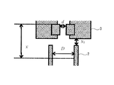
図2は管2とノズル3の寸法関係を定義したものである。xはノズル上流側角部から圧痕の上流端と下流端の中心までの距離(スタンドオフ距離)、dはノズル口径、Dは管内径、x1はノズル先端と管2との距離である。ここで、スタンドオフ距離xは、本発明のキャビテーション気泡の崩壊領域に相当する。
FIG. 2 defines the dimensional relationship between the
そして8は管内径D、ノズル口径d、スタンドオフ距離xを入力する入力手段、9はこの入力手段8に入力された管内径D、ノズル口径d、スタンドオフ距離xに応じて前記噴射圧力p1及び管内部の圧力p2を求め、この圧力p1及びp2となるように流量制御弁5及び圧力制御弁7を制御する制御手段である。
8 is an input means for inputting the tube inner diameter D, nozzle diameter d, and standoff distance x, and 9 is the injection pressure p1 according to the tube inner diameter D, nozzle diameter d, and standoff distance x input to the input means 8. And a control means for obtaining the pressure p2 inside the pipe and controlling the
したがって、管2をタンク1内で管2の内部が水で充満するように設置して、ノズル3から高圧水を管2の内部に噴射して、噴流まわりにキャビテーション10を発生させ,キャビテーション気泡を管2の内部の表面に当てる。これにより、キャビテーション気泡の崩壊衝撃力が管2の内部の表面に作用して、管2の内部の応力腐食割れを防止したり,疲労強度を向上したり,あるいはバリ取りを行う等、管2の内部の表面を改質したり、あるいは、管2の内部を洗浄したり、管2の内部の表面の加工硬化、残留応力改善、疲労強度改善、洗浄効果などをもたらす。
Therefore, the
そこで、本出願人は、管内径D、ノズル口径d、噴射圧力p1、管内部の圧力p2を種々の条件において試験し,スタンドオフ距離xを調べた結果,
上記数式1中の
![]()
![]()
![]()
![]()
したがって、予め実験により,定数のc1とc2を求めておき,処理する管内径Dとスタンドオフ距離xに応じて,ノズル口径d,噴射圧力p1,管内部の圧力p2を選定して処理を行う。 Accordingly, constants c1 and c2 are obtained in advance by experiment, and the nozzle diameter d, the injection pressure p1, and the pressure p2 inside the pipe are selected according to the pipe inner diameter D and the standoff distance x to be processed. .
一般に,キャビテーション噴流におけるキャビテーション発達・崩壊領域は,キャビテーション数の関数であり,
![]()
![]()
細い管内にキャビテーション噴流を流し込む場合について考えてみる。キャビテーション噴流よりも細い管にキャビテーションを流し込むと,一定量のキャビテーションが存在した場合には,直径Dの3乗に逆比例してキャビテーションが長くなる。またDに逆比例して流速が増大する。よって,一定量のキャビテーションが管内を下流に運ばれて崩壊することを考えると,x D4が一定となると考えられる。 Consider the case where a cavitation jet is poured into a narrow pipe. When cavitation is poured into a pipe that is narrower than the cavitation jet, if a certain amount of cavitation exists, the cavitation increases in inverse proportion to the cube of the diameter D. In addition, the flow rate increases in inverse proportion to D. Thus, considering that a certain amount of cavitation is carried downstream in the pipe and collapses, x D 4 is considered to be constant.
一方,キャビテーション噴流は,dの2乗に比例してキャビテーションの発生量が増え(その分だけ下流に流れる),さらに流速もdの2乗に比例して増大すると考えられる。よって,x / d にキャビテーションの発生量(体積)2乗と,流速の2乗を勘案すると,x / d 5 = 一定,となる。 On the other hand, the amount of cavitation generated in the cavitation jet increases in proportion to the square of d (flows downstream by that amount), and the flow velocity also increases in proportion to the square of d. Therefore, x / d 5 = constant, taking into account the amount of cavitation (volume) squared and the square of the flow velocity in x / d.
上記の数式1は以下の実験により求められた。図3はキャビテーション噴流試験装置を示す。実験では最大吐出し圧力30MPa、最大吐出し量3.0×10⁻²m3/minのポンプ100によりキャビテーション噴流を内径D=8〜18 mmのアルミニウム管101内に噴射した。なお、ポンプ100からノズル102の途中に高圧プランジャポンプ103を設けて、噴射圧力p1を調節した。また供試管101下流に弁104を取り付けて供試管内圧力p2を調節した。p1及びp2には絶対圧力を用いた。105、106は圧力ゲージ、107は弁である。キャビテーション噴流によってアルミニウム管内に生じた圧痕の上流端と下流端を目視により計測し、その範囲を処理領域とした。なお、図2の寸法定義はそのまま採用する。
The above
本実験では、上記管内径D、ノズル口径dの条件に加え、キャビテーション噴流の噴射条件を噴射圧力p1および管内部の圧力p2を調節することで変化させ、種々の条件により、処理領域の変化を調べた。噴射時間は10分間一定とし、キャビテーション数κは、ノズル上流側圧力p1、ノズル下流側圧力p2および資料水の飽和蒸気圧pvから以下のように定義した。
![]()
![]()
残留応力測定用の供試管にはD=10mm,肉厚2.5mmのステンレス管を用いた。残留応力は、供試管を切断し、X線回折式応力測定装置を用いて、管の残留応力σθを測定した。なお、応力定数には−369.5Mpa/deg.を用いた。 A stainless steel tube having D = 10 mm and a wall thickness of 2.5 mm was used as a test tube for measuring residual stress. For the residual stress, the test tube was cut, and the residual stress σ θ of the tube was measured using an X-ray diffraction type stress measuring device. The stress constant was −369.5 Mpa / deg.
実験結果について説明する。図4は、D = 8〜18 mmのアルミニウム管をx1=0mm、d=1.8mmでキャビテーション噴流を行った場合について、κとxの関係を、p1 = 30 MPaで処理した場合について、両対数グラフ上に示したものである。なお、図中Iは、圧痕の上流端と下流端の平均値を示す。また、図5は、図4と同様のデータを、xをD4 / d 5で無次元化して、κについて示す。これにより、Dが異なる場合には、κが同一でも、xは大きく異なる。しかし無次元化パラメータxD4 / d 5を用いると、κとxは両対数グラフ上で直線関係にある。 The experimental results will be described. FIG. 4 shows a case where an aluminum tube having D = 8 to 18 mm is subjected to a cavitation jet at x 1 = 0 mm and d = 1.8 mm, and the relationship between κ and x is treated at p 1 = 30 MPa. This is shown on the log-log graph. In the figure, I indicates the average value of the upstream end and the downstream end of the indentation. Further, FIG. 5 shows the same data as FIG. 4 with respect to κ by making x dimensionless by D 4 / d 5 . Thus, when D is different, x is greatly different even if κ is the same. However, if the dimensionless parameter xD 4 / d 5 is used, κ and x are in a linear relationship on the log-log graph.
図6は、D =10mmのアルミニウム管をp1 = 30 MPa、x1=10mm、でキャビテーション噴流を行った場合について、κとxの関係を1.4mm、1.8mm、2.0mmで処理した場合について、両対数グラフ上に示したものである。また、図7は、図6と同様のデータを、xをD4 / d 5で無次元化して、κについて示す。これにより、dが異なる場合にも,κが同一でも,xは大きく異なる。しかし無次元化パラメータxD4 / d 5を用いると、κとxは両対数グラフ上で直線関係にある。 Fig. 6 shows the case where the relationship between κ and x is 1.4 mm, 1.8 mm, and 2.0 mm when a cavitation jet is performed on an aluminum tube with D = 10 mm at p 1 = 30 MPa and x 1 = 10 mm. It is shown on the log-log graph. FIG. 7 shows the same data as FIG. 6 with respect to κ by making x non-dimensional with D 4 / d 5 . Thus, even when d is different, x is greatly different even if κ is the same. However, if the dimensionless parameter xD 4 / d 5 is used, κ and x are in a linear relationship on the log-log graph.
この直線関係を用いることにより,処理する管内径Dと処理領域xに応じて,直径d,噴射圧力p1,管内圧力p2を選定して処理を行うことができる。 By using this linear relationship, the diameter d, the injection pressure p1, and the in-pipe pressure p2 can be selected according to the pipe inner diameter D and the processing region x to be processed.
したがって、制御手段にはこれらの関数が記憶手段(図示せず)に記憶されている。そして、入力手段7に管内径D、ノズル口径d、スタンドオフ距離xが入力されると、記憶手段に記憶されている関数により噴射圧力p1及び管内部の圧力p2を求め、この圧力p1及びp2となるように制御手段により流量制御弁5及び圧力制御弁6が制御される。
これにより、管2の内部の所定のスタンドオフ距離xにおいて、キャビテーション気泡の崩壊衝撃力を作用させることができ、効率が良い処理が可能となる。
Therefore, these functions are stored in the storage means (not shown) in the control means. When the pipe inner diameter D, the nozzle diameter d, and the standoff distance x are input to the input means 7, the injection pressure p1 and the pressure p2 inside the pipe are obtained by the functions stored in the storage means, and these pressures p1 and p2 The flow
Thereby, the collapsing impact force of the cavitation bubbles can be applied at a predetermined standoff distance x inside the
管内径D = 10 mm,肉厚2.5 mmのステンレス管を用いて,p1= 30 MPa, d = 2.0 mm,p2= 1.1 MPa (κ= 0.037)で処理を行った。その結果,図8に示すように、x= 80 mm前後にσθ= 330 MPa程度の圧縮残留応力を導入できた。 Using a stainless steel tube with a tube inner diameter D = 10 mm and a wall thickness of 2.5 mm, treatment was performed at p 1 = 30 MPa, d = 2.0 mm, and p 2 = 1.1 MPa (κ = 0.037). As a result, as shown in FIG. 8, was introduced sigma theta = 330 MPa approximately compressive residual stress in the longitudinal x = 80 mm.
実施例1と同様な管の内部にペイントを塗布して実施例1と同様な試験を行った結果,x= 80 mm前後でペイントが剥がれ,管内の洗浄が可能であることが判明した。 As a result of applying the paint to the inside of the tube similar to that in Example 1 and conducting the same test as in Example 1, it was found that the paint peeled off at around x = 80 mm and that the inside of the tube could be cleaned.
実施例1と同様な管に直径1 mm〜2 mm程度の孔をドリルで空けて,バリを管内面に突出させて,実施例1と同様な試験を行った結果,x = 80 mm前後の孔のバリが取れた。 As a result of drilling a hole with a diameter of about 1 mm to 2 mm in a pipe similar to that in Example 1 and projecting a burr on the inner surface of the pipe, the same test as in Example 1 was performed. The hole was deburred.
本発明の効果について説明する。
請求項1に係る発明によれば、所定の管内部のキャビテーション気泡の崩壊領域にキャビテーション気泡の崩壊衝撃力を作用させることができるので、効率が良い処理が可能となる。そして、管内径Dとキャビテーション気泡の崩壊領域xに応じて,ノズル口径d,噴射圧力p1,管内部の圧力p2を選定して処理を行うことができる。
The effect of the present invention will be described.
According to the first aspect of the present invention, since the collapsing impact force of the cavitation bubbles can be applied to the collapse region of the cavitation bubbles inside the predetermined pipe, efficient processing can be performed. Then, according to the pipe inner diameter D and the collapse region x of the cavitation bubble, the nozzle diameter d, the injection pressure p1, and the pressure p2 inside the pipe can be selected for processing.
請求項2に係る発明によれば、クッション効果によるキャビテーション衝撃力が弱まることはない。
According to the invention which concerns on
請求項3に係る発明によれば、安価に実施することができる。
According to the invention which concerns on
請求項4に係る発明によれば、適切に所定の管内部のキャビテーション気泡の崩壊領域にキャビテーション気泡の崩壊衝撃力が作用した管が得られる。
According to the invention which concerns on
請求項5に係る発明によれば、簡単に所定の管内部のキャビテーション気泡の崩壊領域にキャビテーション気泡の崩壊衝撃力作用させることができる。 According to the fifth aspect of the present invention, the collapsing impact force of the cavitation bubbles can be easily applied to the collapse region of the cavitation bubbles inside the predetermined pipe.
1 タンク
2 管
3 ノズル
4 管路
5 流量制御弁(第1圧力制御手段)
6 管路
7 圧力制御弁(第2圧力制御手段)
8 入力手段
9 制御手段
10 キャビテーション
100 ポンプ
101 アルミニウム管(供試管)
102 ノズル
103 高圧プランジャポンプ
104、107 弁
105、106 圧力ゲージ
1
6 Pipe line 7 Pressure control valve (second pressure control means)
8 Input means 9 Control means 10
102
Claims (5)
前記管内径と前記ノズル口径に応じて、前記高圧液体の噴射圧力と前記管内部の圧力を制御することにより前記管内部のキャビテーション気泡の崩壊領域を制御する管内部の表面改質または洗浄方法において、
前記管内径D,前記ノズル口径d,前記高圧液体の噴射圧力p1,前記管内部圧力p2,前記崩壊領域xとした場合、以下の関係式が成立することを特徴とする管内部の表面改質または洗浄方法。
Depending on the nozzle opening diameter as the pipe diameter, the injection pressure and surface modification of the tube interior that controls the collapse area of cavitation bubbles of the tube portion by controlling the pressure of the pipe portion of the high pressure liquid In quality or cleaning method ,
When the pipe inner diameter D, the nozzle diameter d, the injection pressure p1 of the high-pressure liquid, the pipe internal pressure p2, and the collapse region x are satisfied, the following relational expression is satisfied: Or cleaning method .
管と、
該管内部に高圧液体を噴射するノズルと、
前記高圧液体の噴射圧力p1を制御する第1圧力制御手段と、
前記管内部の圧力p2を制御する第2圧力制御手段と、
前記管内径Dと前記ノズル口径dに応じて、前記高圧液体の噴射圧力p1と前記管内部の圧力p2を制御することにより前記管内部のキャビテーション気泡の崩壊領域xを制御する制御手段と、
を備えたことを特徴とする管内部の表面改質または洗浄装置。 In a surface modification or cleaning device in a tube used in the method according to any one of claims 1 to 3 ,
Tube,
A nozzle for injecting high-pressure liquid into the tube;
First pressure control means for controlling the injection pressure p1 of the high-pressure liquid;
Second pressure control means for controlling the pressure p2 inside the pipe;
Control means for controlling the collapse region x of the cavitation bubbles inside the pipe by controlling the injection pressure p1 of the high-pressure liquid and the pressure p2 inside the pipe according to the pipe inner diameter D and the nozzle diameter d;
A device for modifying or cleaning the surface of a pipe, characterized by comprising:
Priority Applications (1)
| Application Number | Priority Date | Filing Date | Title |
|---|---|---|---|
| JP2006055970A JP4635206B2 (en) | 2006-03-02 | 2006-03-02 | Method for surface modification or cleaning inside tube, and device for surface modification or cleaning inside tube used in the method |
Applications Claiming Priority (1)
| Application Number | Priority Date | Filing Date | Title |
|---|---|---|---|
| JP2006055970A JP4635206B2 (en) | 2006-03-02 | 2006-03-02 | Method for surface modification or cleaning inside tube, and device for surface modification or cleaning inside tube used in the method |
Publications (2)
| Publication Number | Publication Date |
|---|---|
| JP2007229650A JP2007229650A (en) | 2007-09-13 |
| JP4635206B2 true JP4635206B2 (en) | 2011-02-23 |
Family
ID=38550774
Family Applications (1)
| Application Number | Title | Priority Date | Filing Date |
|---|---|---|---|
| JP2006055970A Active JP4635206B2 (en) | 2006-03-02 | 2006-03-02 | Method for surface modification or cleaning inside tube, and device for surface modification or cleaning inside tube used in the method |
Country Status (1)
| Country | Link |
|---|---|
| JP (1) | JP4635206B2 (en) |
Families Citing this family (3)
| Publication number | Priority date | Publication date | Assignee | Title |
|---|---|---|---|---|
| JP5463985B2 (en) * | 2010-03-17 | 2014-04-09 | 株式会社リコー | Image forming apparatus |
| CN109773406B (en) * | 2019-02-21 | 2020-12-08 | 江苏大学 | A surface cavitation and no-pellet strengthening treatment device |
| CN110157879B (en) * | 2019-04-28 | 2020-11-03 | 江苏大学 | Integrated processing system and method for polishing and strengthening surface of additive manufacturing forming inner hole |
Family Cites Families (1)
| Publication number | Priority date | Publication date | Assignee | Title |
|---|---|---|---|---|
| JP4176197B2 (en) * | 1998-08-12 | 2008-11-05 | 関西電力株式会社 | A method to improve the internal residual stress state of small diameter pipes |
-
2006
- 2006-03-02 JP JP2006055970A patent/JP4635206B2/en active Active
Also Published As
| Publication number | Publication date |
|---|---|
| JP2007229650A (en) | 2007-09-13 |
Similar Documents
| Publication | Publication Date | Title |
|---|---|---|
| JP3162104B2 (en) | Method for improving residual stress of metallic materials | |
| EP1170387B1 (en) | Surface refining and cleaning method for metal parts or the like and device therefor | |
| JP7157994B2 (en) | A method for generating ultra-high temperature and high pressure cavitation, a method for applying compressive residual stress to the surface of a material and changing surface geometry, mechanical properties and corrosion resistance, and an ultra-high temperature and high pressure cavitation generating apparatus | |
| Soyama et al. | Fatigue strength improvement of gears using cavitation shotless peening | |
| JP5578318B2 (en) | Cavitation generator | |
| EP3366416B1 (en) | Water jet peening method | |
| CN101293230A (en) | Vented nozzle and adjustable cavitation water peening method | |
| Lu et al. | Experimental investigation on the performance of improving jet pump cavitation with air suction | |
| JP4635206B2 (en) | Method for surface modification or cleaning inside tube, and device for surface modification or cleaning inside tube used in the method | |
| JP5352600B2 (en) | Method and apparatus for improving residual stress by water jet peening for pipe inner surface | |
| JP5996348B2 (en) | Cavitation nozzle | |
| JPH07328857A (en) | Water jet peening apparatus and water jet peening method | |
| JP2991545B2 (en) | Residual stress improving method, residual stress improving device, and nozzle for water jet peening | |
| CN104673972B (en) | A kind of jet shot-blast unit | |
| JP4176197B2 (en) | A method to improve the internal residual stress state of small diameter pipes | |
| JP2002200528A (en) | Residual stress reducing method for small-bore pipe interior surface | |
| JP4729282B2 (en) | Method and apparatus for improving residual stress by water jet peening for pipe inner surface | |
| JP5627761B2 (en) | Water jet peening method | |
| JP2010214477A (en) | Surface treatment method and device | |
| Soyama et al. | Improvement of the fatigue strength of stainless steel SUS316L by a cavitating jet with an associated water jet in water | |
| Soyama et al. | Optimum injection pressure of a cavitating jet for introducing compressive residual stress into stainless steel | |
| JP3315153B2 (en) | Cavitation jet nozzle | |
| Soyama et al. | Improvement of fatigue strength on stainless steel by cavitating jet in air | |
| Sekine et al. | Surface modification of alloy tool steel for forging dies by cavitation peening | |
| Macodiyo et al. | Effect of cavitation number on the improvement of fatigue strength of carburized steel using cavitation shotless peening |
Legal Events
| Date | Code | Title | Description |
|---|---|---|---|
| A621 | Written request for application examination |
Free format text: JAPANESE INTERMEDIATE CODE: A621 Effective date: 20081107 |
|
| A977 | Report on retrieval |
Free format text: JAPANESE INTERMEDIATE CODE: A971007 Effective date: 20100805 |
|
| A131 | Notification of reasons for refusal |
Free format text: JAPANESE INTERMEDIATE CODE: A131 Effective date: 20100817 |
|
| A521 | Request for written amendment filed |
Free format text: JAPANESE INTERMEDIATE CODE: A523 Effective date: 20101001 |
|
| TRDD | Decision of grant or rejection written | ||
| A01 | Written decision to grant a patent or to grant a registration (utility model) |
Free format text: JAPANESE INTERMEDIATE CODE: A01 Effective date: 20101026 |
|
| A01 | Written decision to grant a patent or to grant a registration (utility model) |
Free format text: JAPANESE INTERMEDIATE CODE: A01 |
|
| R150 | Certificate of patent or registration of utility model |
Free format text: JAPANESE INTERMEDIATE CODE: R150 |