JP4635197B2 - Oxidation catalyst for exhaust gas purification and method for producing the same - Google Patents
Oxidation catalyst for exhaust gas purification and method for producing the same Download PDFInfo
- Publication number
- JP4635197B2 JP4635197B2 JP2005080679A JP2005080679A JP4635197B2 JP 4635197 B2 JP4635197 B2 JP 4635197B2 JP 2005080679 A JP2005080679 A JP 2005080679A JP 2005080679 A JP2005080679 A JP 2005080679A JP 4635197 B2 JP4635197 B2 JP 4635197B2
- Authority
- JP
- Japan
- Prior art keywords
- oxidation catalyst
- powder
- catalyst
- composition formula
- exhaust gas
- Prior art date
- Legal status (The legal status is an assumption and is not a legal conclusion. Google has not performed a legal analysis and makes no representation as to the accuracy of the status listed.)
- Expired - Lifetime
Links
Images


Landscapes
- Exhaust Gas After Treatment (AREA)
- Exhaust Gas Treatment By Means Of Catalyst (AREA)
- Catalysts (AREA)
Description
本発明は排ガス浄化用酸化触媒及びその製造方法に関する。本発明に係る排ガス浄化用酸化触媒は、例えば、自動車や自動二輪車等の内燃機関やボイラー等の各種燃焼装置から排出される排ガス中の、特に炭化水素(HC)を効率良く浄化できる排ガス浄化用触媒に好適に利用することができる。 The present invention relates to an oxidation catalyst for exhaust gas purification and a method for producing the same. The oxidation catalyst for exhaust gas purification according to the present invention is for exhaust gas purification capable of efficiently purifying hydrocarbons (HC) in exhaust gas discharged from various combustion apparatuses such as internal combustion engines such as automobiles and motorcycles and boilers, for example. It can utilize suitably for a catalyst .
自動二輪車や自動車のエンジンから排出される排ガスには、一酸化炭素(CO)、炭化水素(HC)、窒素酸化物(NOx)や硫黄酸化物(SOx)などが含まれており、この排ガスによる環境汚染の問題は都市部を中心に深刻化している。 The exhaust gas emitted from motorcycles and automobile engines contains carbon monoxide (CO), hydrocarbons (HC), nitrogen oxides (NOx) and sulfur oxides (SOx). The problem of environmental pollution is getting worse, especially in urban areas.
近年、大気汚染防止法に基づき、炭化水素や窒素酸化物の大幅な削減を目標とした新しい基準が、告示されている。これによれば、例えば、四輪車に比べて安価で、手軽な交通手段として広く利用されている自動二輪車は、車両全体に占める排出寄与度も高く、排ガス規制が大幅に強化される予定である。具体的には、2006〜2007年以降に販売される自動二輪車は、現行値比で、炭化水素については75〜85%の低減率、窒素酸化物については50%の低減率、一酸化炭素については85%の低減率という、厳しいレベルの目標値が要求される。 In recent years, new standards have been announced based on the Air Pollution Control Law, with the goal of drastically reducing hydrocarbons and nitrogen oxides. According to this, for example, motorcycles, which are cheaper and easier to use than four-wheeled vehicles, are widely used as a means of transportation, and have a high contribution to emissions in the entire vehicle. is there. Specifically, motorcycles sold after 2006-2007 are compared to current values, with 75-85% reduction for hydrocarbons, 50% reduction for nitrogen oxides, and carbon monoxide. Requires a strict target value of 85% reduction.
こうした状況下、四輪車用の触媒を二輪車に使用することが種々検討されているが、白金等の高価な貴金属を触媒成分として用いる四輪車用触媒を二輪車に利用することは割高感が強い。このため、より安価な二輪車用排ガス浄化触媒の開発が切望されている。 Under such circumstances, various studies have been made on using a catalyst for a four-wheeled vehicle for a two-wheeled vehicle, but it is expensive to use a catalyst for a four-wheeled vehicle using an expensive noble metal such as platinum as a catalyst component. strong. For this reason, development of a cheaper exhaust gas purification catalyst for motorcycles is eagerly desired.
ここに、貴金属触媒と比べて安価でかつ酸化触媒としての利用が可能なものとして、無機化合物よりなる活性酸素発現物質が知られている(例えば、特許文献1参照)。 Here, an active oxygen-expressing substance made of an inorganic compound is known as one that is cheaper than a noble metal catalyst and can be used as an oxidation catalyst (see, for example, Patent Document 1).
この活性酸素発現物質は、活性酸素種を内包する12CaO・7Al2 O3 化合物であり、カルシウムとアルミニウムとを12:14の原子当量比で混合した原料粉末を用いて、酸素分圧104 Pa以上、好ましくは105 Pa以上、水素分圧1Pa以下に厳密に制御された乾燥酸化雰囲気で、焼成温度1200℃以上、好ましくは1300℃の高温度の条件下で固相反応させることにより製造される。 This active oxygen-expressing substance is a 12CaO · 7Al 2 O 3 compound containing active oxygen species, and a raw material powder in which calcium and aluminum are mixed at an atomic equivalent ratio of 12:14 is used to generate an oxygen partial pressure of 10 4 Pa. Above, preferably produced by a solid phase reaction in a dry oxidation atmosphere strictly controlled to 10 5 Pa or higher and a hydrogen partial pressure of 1 Pa or lower under a high temperature condition of a firing temperature of 1200 ° C. or higher, preferably 1300 ° C. The
このような活性酸素発現物質については研究例が種々報告されているが、さらに実用価値の高い新しい活性酸素発現物質の開発が強く要請されていた。 Although various research examples have been reported for such active oxygen-expressing substances, there has been a strong demand for the development of new active oxygen-expressing substances with higher practical value.
そこで、本発明者等は、新規な活性酸素発現物質の開発を目的として鋭意研究を重ねた結果、活性酸素であるスーパーオキサイドアニオン(O2 - )を構造中に内包した、A2 B2 O5 (A:アルカリ又はアルカリ土類元素、B:遷移元素)の組成式を有する無機化合物が、高い活性酸素発現能力を有して酸化触媒として有用であることを見出し、さらに研究を重ねて先に発明している(特願2004−119782号)。 Therefore, as a result of intensive studies aimed at developing a novel active oxygen-expressing substance, the present inventors have found that A 2 B 2 O containing superoxide anion (O 2 − ), which is active oxygen, included in the structure. 5 An inorganic compound having the composition formula (A: alkali or alkaline earth element, B: transition element) has been found to be useful as an oxidation catalyst with high active oxygen expression ability, and further research has been conducted. (Japanese Patent Application No. 2004-119882).
この活性酸素発現物質として、具体的にはCa2Fe2O5の組成式を有するカルシウムフェライトが挙げられており、これはCaCO 3 とFe2O3とを2:1のモル比で混合した原料粉末を酸素雰囲気で800℃以上に加熱することにより製造される。 Specific examples of the active oxygen-expressing substance include calcium ferrite having a composition formula of Ca 2 Fe 2 O 5 , which is a mixture of Ca CO 3 and Fe 2 O 3 in a molar ratio of 2: 1. The raw material powder is manufactured by heating to 800 ° C. or higher in an oxygen atmosphere.
ところが、上述したCa2 Fe2 O5 の組成式を有するカルシウムフェライトは高い触媒活性を示し、酸化触媒としての利用が大きく期待できるものではあるが、Ca2 Fe2 O5 という特定の組成式をねらって製造することが現実的には困難であるという問題がある。 However, calcium ferrite having the above-described composition formula of Ca 2 Fe 2 O 5 exhibits high catalytic activity and can be expected to be used as an oxidation catalyst. However, a specific composition formula of Ca 2 Fe 2 O 5 is used. There is a problem that it is actually difficult to manufacture with the aim.
すなわち、理論的には、上述したとおりCaCO 3 とFe2O3とを2:1のモル比で混合した原料粉末を酸素雰囲気で800℃以上に加熱すれば、Ca2Fe2O5の組成式を有するカルシウムフェライトを製造することができる。しかし、現実的には、平衡論及び速度論的理由などから目的の組成や均一な結晶相をもつ化合物をコマーシャルベースで得ることが困難である。
That is, theoretically, as described above, if the raw material powder in which
本発明は上記実情に鑑みてなされたものであり、酸化触媒として高い触媒活性を示し、安価かつ容易に得ることのできる排ガス浄化用酸化触媒を提供することを解決すべき技術課題とするものである。 The present invention has been made in view of the above circumstances, and it is a technical problem to be solved to provide an oxidation catalyst for exhaust gas purification that exhibits high catalytic activity as an oxidation catalyst and can be obtained inexpensively and easily. is there.
上記課題を解決する本発明の排ガス浄化用酸化触媒は、少なくとも、活性酸素を構造中に内包した活性酸素発現物質であるCaFe2O4の組成式を有するカルシウムフェライトを含むことを特徴とするものである。 The oxidation catalyst for exhaust gas purification of the present invention that solves the above-mentioned problem is characterized by containing at least calcium ferrite having a composition formula of CaFe 2 O 4 which is an active oxygen-expressing substance having active oxygen included in the structure. It is.
本発明の排ガス浄化用酸化触媒は、好適な態様において、活性酸素を構造中に内包した活性酸素発現物質であるCa2Fe2O5の組成式を有するカルシウムフェライトをさらに含む。 In a preferred embodiment, the exhaust gas purifying oxidation catalyst of the present invention further includes calcium ferrite having a composition formula of Ca 2 Fe 2 O 5 , which is an active oxygen-expressing substance in which active oxygen is included in the structure .
本発明の排ガス浄化用酸化触媒は、好適な態様において、Fe2O3をさらに含む。 In a preferred embodiment, the exhaust gas purifying oxidation catalyst of the present invention further contains Fe 2 O 3 .
上記課題を解決する本発明の排ガス浄化用酸化触媒の製造方法は、カルシア源とフェライト源とを所定の混合モル比Ca/Feで含む混合原料を得る混合原料準備工程と、該混合原料を酸素雰囲気で600℃以上に加熱する焼成工程とを備え、前記焼成工程では、前記混合モル比Ca/Feが、1.0≦Ca/Feであるときは1438℃以下の加熱温度で、0.5≦Ca/Fe<1であるときは1216℃以下の加熱温度で、0.25≦Ca/Fe<0.5であるときは1205℃以下の加熱温度で、0<Ca/Fe<0.25であるときは1226℃以下の加熱温度で、それぞれ加熱することにより、活性酸素を構造中に内包したCa2Fe2O5の組成式を有するカルシウムフェライト及び活性酸素を構造中に内包したCaFe2O4の組成式を有するカルシウムフェライトのうちの少なくとも一種を含む酸化触媒を製造することを特徴とするものである。 The method for producing an exhaust gas purifying oxidation catalyst of the present invention that solves the above problems includes a mixed raw material preparation step for obtaining a mixed raw material comprising a calcia source and a ferrite source at a predetermined mixing molar ratio Ca / Fe, and the mixed raw material as oxygen. A baking step of heating to 600 ° C. or more in an atmosphere, and in the baking step, when the mixed molar ratio Ca / Fe is 1.0 ≦ Ca / Fe, the heating temperature is 1438 ° C. or less, and 0.5 When ≦ Ca / Fe <1, the heating temperature is 1216 ° C. or less, and when 0.25 ≦ Ca / Fe <0.5, the heating temperature is 1205 ° C. or less, and 0 <Ca / Fe <0.25. a heating temperature of 1226 ° C. or less when it is, by heating respectively, CaFe 2 which encloses the calcium ferrite and active oxygen having a composition formula of Ca 2 Fe 2 O 5 containing therein the active oxygen in the structure in its structure An oxidation catalyst containing at least one of calcium ferrites having a composition formula of O 4 is manufactured.
ここに、混合原料にはかならずカルシア源及びフェライト源の双方が含まれている。 Here, the mixed raw material always includes both the calcia source and the ferrite source.
好適な態様において、前記混合原料準備工程では、前記混合モル比を、0.33≦Ca/Fe≦3.0とする。 In a preferred embodiment, in the mixed raw material preparation step, the mixing molar ratio is set to 0.33 ≦ Ca / Fe ≦ 3.0.
本発明の排ガス浄化用酸化触媒は、少なくとも、活性酸素を構造中に内包した活性酸素発現物質であるCaFe2O4の組成式を有するカルシウムフェライトを含む。 The oxidation catalyst for exhaust gas purification of the present invention includes at least calcium ferrite having a composition formula of CaFe 2 O 4 which is an active oxygen-expressing substance having active oxygen included in the structure .
本発明の排ガス浄化用酸化触媒の使用形態としては特に限定されない。例えば、粉末からなる酸化触媒、粉末を所定形状に成形した成形体からなる酸化触媒、あるいは担体とこの担体上に担持された触媒粉末とからなる酸化触媒として、本発明の排ガス浄化用酸化触媒を使用することができる。そして、これらの酸化触媒を構成する構成要素の少なくとも一部に、活性酸素を構造中に内包した活性酸素発現物質であるCaFe2O4の組成式を有するカルシウムフェライトを含む。すなわち、本発明の排ガス浄化用酸化触媒は、酸化触媒として使用に供される際の使用形態において、構成要素の少なくとも一部に活性酸素を構造中に内包した活性酸素発現物質であるCaFe2O4の組成式を有するカルシウムフェライトを含む。 The usage form of the oxidation catalyst for exhaust gas purification of the present invention is not particularly limited. For example, the oxidation catalyst for purification of exhaust gas according to the present invention is used as an oxidation catalyst composed of powder, an oxidation catalyst composed of a molded body obtained by molding powder into a predetermined shape, or an oxidation catalyst composed of a carrier and a catalyst powder supported on the carrier. Can be used. And at least a part of the constituent elements constituting these oxidation catalysts includes calcium ferrite having a composition formula of CaFe 2 O 4 which is an active oxygen-expressing substance in which active oxygen is included in the structure . That is, the exhaust gas purifying oxidation catalyst of the present invention is a CaFe 2 O which is an active oxygen-expressing substance in which active oxygen is included in the structure in at least a part of the constituent elements when used as an oxidation catalyst. Calcium ferrite having a composition formula of 4 is included.
例えば、粉末からなる酸化触媒として使用に供される場合は、該粉末が単独の粉末よりなるときはその単独の粉末がCaFe2 O4 の組成式を有するカルシウムフェライトよりなり、また、該粉末が複数種の混合粉末よりなるときはその混合粉末を構成する一種の粉末がCaFe2 O4 の組成式を有するカルシウムフェライトよりなる態様とすることができる。 For example, when used as an oxidation catalyst composed of powder, when the powder is composed of a single powder, the single powder is composed of calcium ferrite having a composition formula of CaFe 2 O 4 , and the powder is when it is formed of a plurality of kinds mixed powder may be a mode in which one of the powder constituting the mixed powder is formed of calcium ferrite having a compositional formula of CaFe 2 O 4.
なお、本願明細書でいう混合粉末とは、単一の結晶相よりなる粉末と、他の単一の結晶相よりなる他の粉末とが混合しているもの以外に、単一の結晶相よりなる粉末と他の単一の結晶相よりなる他の粉末とが付着することにより、見かけ状は1個の粉末となっているようなものも含む意味である。 In addition, the mixed powder as used in this specification refers to a single crystal phase other than a mixture of a powder composed of a single crystal phase and another powder composed of another single crystal phase. It is meant that the apparent shape includes one powder by adhering to the other powder and another powder composed of another single crystal phase.
粉末を所定形状に成形した成形体からなる酸化触媒として使用に供される場合も同様に、該粉末が単独の粉末よりなるときはその単独の粉末がCaFe2 O4 の組成式を有するカルシウムフェライトよりなり、また、該粉末が複数種の混合粉末よりなるときはその混合粉末を構成する一種の粉末がCaFe2 O4 の組成式を有するカルシウムフェライトよりなる態様とすることができる。 Similarly, when used as an oxidation catalyst comprising a molded body obtained by molding a powder into a predetermined shape, when the powder is composed of a single powder, the single powder has a composition formula of CaFe 2 O 4 Further, when the powder is composed of a plurality of kinds of mixed powders, one kind of powder constituting the mixed powder can be made of calcium ferrite having a composition formula of CaFe 2 O 4 .
担体とこの担体上に担持された触媒粉末とからなる酸化触媒として使用に供される場合は、該触媒粉末が単独の粉末よりなるときはその単独の粉末がCaFe2 O4 の組成式を有するカルシウムフェライトよりなり、また、該触媒粉末が複数種の混合粉末よりなるときはその混合粉末を構成する一種の粉末がCaFe2 O4 の組成式を有するカルシウムフェライトよりなる態様とされたり、あるいは該担体が少なくともCaFe2 O4 の組成式を有するカルシウムフェライトを含む態様とすることができる。 When used as an oxidation catalyst comprising a support and a catalyst powder supported on the support, when the catalyst powder is composed of a single powder, the single powder has a composition formula of CaFe 2 O 4 When the catalyst powder is composed of a plurality of kinds of mixed powders, one type of powder constituting the mixed powder is made of calcium ferrite having a composition formula of CaFe 2 O 4 , or The support may contain calcium ferrite having a composition formula of at least CaFe 2 O 4 .
成形体の形状は、使用目的に併せて任意に決定され、顆粒、平板、柱状、円筒管、中空糸、モノリスやハニカムなどが例示される。また、成形時には形状とともに成形体の緻密さ、あるいは多孔質化が求められ、これらはその使用目的等に応じて、任意に設計することができる。成形方法としては、セラミックス成形体の製造において使用される通常の方法を用いることができ、例えば、鋳込み成形、加圧成形、乾式CIP成形、射出成形、シート成形などを使用することができる。 The shape of the molded body is arbitrarily determined according to the purpose of use, and examples thereof include granules, flat plates, columns, cylindrical tubes, hollow fibers, monoliths, and honeycombs. Further, at the time of molding, it is required to have a compact or porous structure along with the shape, and these can be arbitrarily designed according to the purpose of use. As a forming method, a normal method used in the production of a ceramic molded body can be used. For example, casting molding, pressure molding, dry CIP molding, injection molding, sheet molding and the like can be used.
本発明の排ガス浄化用酸化触媒は、CaFe 2 O 4 の組成式を有するカルシウムフェライトの他に、例えば、Ca2Fe2O5の組成式を有するカルシウムフェライトをさらに含んでいたり、あるいはFe2O3をさらに含んでいたりしてもよい。また、CaO、CaFe4O7、Ca4Fe14O25等の他の酸化触媒成分をさらに含んでいてもよい。また、場合によっては、白金やパラジウム等の貴金属粉末と同時に使用に供されてもよい。 The oxidation catalyst for exhaust gas purification of the present invention further includes, for example, calcium ferrite having a composition formula of Ca 2 Fe 2 O 5 in addition to calcium ferrite having a composition formula of CaFe 2 O 4 , or Fe 2 O 3 may be further included. Moreover, other oxidation catalyst components such as CaO, CaFe 4 O 7 , and Ca 4 Fe 14 O 25 may be further included. Moreover, depending on the case, you may use simultaneously with noble metal powders, such as platinum and palladium.
このように、少なくとも、活性酸素を構造中に内包した活性酸素発現物質であるCaFe2O4の組成式を有するカルシウムフェライトを含む本発明の排ガス浄化用酸化触媒は、CaFe2O4の組成式を有するカルシウムフェライトが示す高い触媒活性により、大きな酸化触媒機能を発揮する。このCaFe2O4の組成式を有するカルシウムフェライトが高い触媒活性を示すメカニズムは必ずしも明らかではないが、以下のように考えることができる。すなわち、CaFe2O4は、200℃程度以上の温度域で圧縮や引っ張り等の力が加わることによって構造中の酸素が不安定となり、これが活性酸素となって、スーパーオキサイドアニオン(O2 −)等の活性酸素を構造中に内包する。そして、このようにCaFe2O4中に内包された活性酸素が外部に放出されると、高い触媒活性を示して大きな酸化触媒機能を発揮する。活性酸素を放出したCaFe2O4には外部からの酸素が構造中に取り込まれる。そして再びCaFe2O4の構造中の酸素が不安定になり、活性酸素として外部に放出される。このようにCaFe2O4は、構造中で不安定となって生成した活性酸素を外部に放出し、外部から酸素を構造中に取り込み、そして再び活性酸素として外部に放出することを繰り返して、大きな酸化触媒機能を発揮すると考えられる。 Thus, at least the oxidation catalyst for exhaust gas purification of the present invention containing calcium ferrite having the composition formula of CaFe 2 O 4 which is an active oxygen-expressing substance having active oxygen encapsulated in the structure is the composition formula of CaFe 2 O 4 . Due to the high catalytic activity exhibited by calcium ferrite having a high oxidation catalyst function, it exhibits a large oxidation catalyst function. The mechanism by which calcium ferrite having the composition formula of CaFe 2 O 4 exhibits high catalytic activity is not necessarily clear, but can be considered as follows. That is, in CaFe 2 O 4 , oxygen in the structure becomes unstable when a force such as compression or tension is applied in a temperature range of about 200 ° C. or higher, and this becomes active oxygen, and superoxide anion (O 2 − ). Such active oxygen is included in the structure. When active oxygen encapsulated in CaFe 2 O 4 is released to the outside in this way, it exhibits high catalytic activity and exhibits a large oxidation catalyst function. CaFe 2 O 4 from which active oxygen has been released incorporates oxygen from the outside into the structure. Then, oxygen in the CaFe 2 O 4 structure becomes unstable again and is released to the outside as active oxygen. Thus, CaFe 2 O 4 repeatedly releases active oxygen that has become unstable in the structure to the outside, takes oxygen into the structure from the outside, and releases it again as active oxygen to the outside. It is thought to exert a large oxidation catalyst function.
また、本発明の排ガス浄化用酸化触媒に含まれうるCa2Fe2O5の組成式を有するカルシウムフェライトも、CaFe2O4の組成式を有するカルシウムフェライトと同様のメカニズムによって、極めて高い触媒活性を示し、極めて大きな酸化触媒機能を発揮する。 In addition, calcium ferrite having a composition formula of Ca 2 Fe 2 O 5 that can be included in the oxidation catalyst for exhaust gas purification of the present invention is also extremely high in catalytic activity by the same mechanism as calcium ferrite having the composition formula of CaFe 2 O 4. And exhibits an extremely large oxidation catalyst function.
なお、後述するCaFe4 O7 の組成式を有するカルシウムフェライトもCaFe2 O4 の組成式を有するカルシウムフェライトと同様のメカニズムによって、高い触媒活性を示し、大きな酸化触媒機能を発揮すると考えられる。 It is considered that calcium ferrite having a composition formula of CaFe 4 O 7 described later also exhibits high catalytic activity and exerts a large oxidation catalyst function by the same mechanism as calcium ferrite having the composition formula of CaFe 2 O 4 .
また、本発明の排ガス浄化用酸化触媒に含まれうるFe2O3及び後述するCaOは、上述したカルシウムフェライトとは異なるメカニズムにより、酸化触媒機能を発揮する。 Further, Fe 2 O 3 that can be included in the oxidation catalyst for exhaust gas purification of the present invention and CaO described later exhibit an oxidation catalyst function by a mechanism different from that of calcium ferrite described above.
本発明の排ガス浄化用酸化触媒は、好適には、カルシア源とフェライト源とを所定の混合モル比で含む混合原料を酸素雰囲気で600℃以上に加熱する焼成処理によって、製造することができる。具体的には、前記混合モル比が、0.5≦Ca/Fe<1.0であるときは600〜1216℃の加熱温度で、0.25≦Ca/Fe<0.5であるときは600〜1205℃の加熱温度で、0<Ca/Fe<0.25であるときは600〜1155℃の加熱温度で、それぞれ前記焼成処理を行うことによって、少なくとも、CaFe2O4の組成式を有するカルシウムフェライト粉末を製造することができる。このとき、前記混合モル比を0.5≦Ca/Fe<1.0として600〜1216℃の加熱温度で焼成したときは、CaFe2O4の組成式を有するカルシウムフェライト粉末と、Ca2Fe2O5の組成式を有するカルシウムフェライト粉末とを理論的には得ることができる。また、前記混合モル比を0.25≦Ca/Fe<0.5として1155〜1205℃の加熱温度で焼成したときは、CaFe2O4の組成式を有するカルシウムフェライト粉末と、CaFe4O7の組成式を有するカルシウムフェライト粉末とを理論的には得ることができる。また、前記混合モル比を0<Ca/Fe<0.5として600〜1155℃の加熱温度で焼成したときは、CaFe2O4の組成式を有するカルシウムフェライト粉末と、Fe2O3(ヘマタイト)粉末とを理論的には得ることができる。 The exhaust gas purifying oxidation catalyst of the present invention can be preferably produced by a firing treatment in which a mixed raw material containing a calcia source and a ferrite source in a predetermined mixing molar ratio is heated to 600 ° C. or higher in an oxygen atmosphere. Specifically, when the mixing molar ratio is 0.5 ≦ Ca / Fe <1.0, the heating temperature is 600 to 1216 ° C., and when 0.25 ≦ Ca / Fe <0.5. When the heating temperature is 600 to 1205 ° C. and 0 <Ca / Fe <0.25, the baking treatment is performed at the heating temperature of 600 to 1155 ° C., so that at least the composition formula of CaFe 2 O 4 is obtained. The calcium ferrite powder which has can be manufactured. At this time, when the mixture molar ratio is set to 0.5 ≦ Ca / Fe <1.0 and calcined at a heating temperature of 600 to 1216 ° C., calcium ferrite powder having a composition formula of CaFe 2 O 4 and Ca 2 Fe A calcium ferrite powder having a composition formula of 2 O 5 can be theoretically obtained. Further, when the mixture molar ratio is 0.25 ≦ Ca / Fe <0.5 and firing is performed at a heating temperature of 1155 to 1205 ° C., calcium ferrite powder having a composition formula of CaFe 2 O 4 and CaFe 4 O 7 In theory, a calcium ferrite powder having the following composition formula can be obtained. When the mixture molar ratio is 0 <Ca / Fe <0.5 and calcined at a heating temperature of 600 to 1155 ° C., calcium ferrite powder having a composition formula of CaFe 2 O 4 and Fe 2 O 3 (hematite) ) The powder can be obtained theoretically.
このように、本発明の排ガス浄化用酸化触媒は、カルシア源及びフェライト源という貴金属に比べて安価な混合原料を用い、その混合原料を酸素雰囲気で所定温度に加熱するという簡易な方法により、製造することができる。しかも、混合原料における混合モル比について、特定の一点をねらって調製する必要がないことから、容易に混合原料を準備することができる。したがって、本発明の排ガス浄化用酸化触媒は、安価かつ容易に得ることが可能となる。 Thus, the oxidation catalyst for exhaust gas purification of the present invention is manufactured by a simple method of using a mixed raw material cheaper than noble metals such as a calcia source and a ferrite source and heating the mixed raw material to a predetermined temperature in an oxygen atmosphere. can do. And since it is not necessary to prepare for the specific molar point about the mixing molar ratio in a mixed raw material, a mixed raw material can be prepared easily. Therefore, the exhaust gas purifying oxidation catalyst of the present invention can be obtained inexpensively and easily.
次に、本発明の排ガス浄化用酸化触媒の製造方法は、混合原料準備工程と、焼成工程とを備え、活性酸素を構造中に内包したCa2Fe2O5の組成式を有するカルシウムフェライト及び活性酸素を構造中に内包したCaFe2O4の組成式を有するカルシウムフェライトのうちの少なくとも一種を含む酸化触媒を製造するものである。 Next, a method for producing an oxidation catalyst for exhaust gas purification according to the present invention includes a mixed raw material preparation step and a firing step, and calcium ferrite having a composition formula of Ca 2 Fe 2 O 5 encapsulating active oxygen in the structure and An oxidation catalyst containing at least one of calcium ferrites having a composition formula of CaFe 2 O 4 in which active oxygen is included in the structure is produced.
混合原料準備工程では、カルシア源とフェライト源とを所定の混合モル比Ca/Feで含む混合原料を得る。 In the mixed raw material preparation step, a mixed raw material containing a calcia source and a ferrite source at a predetermined mixing molar ratio Ca / Fe is obtained.
上記カルシア源としては特に限定されず、酸化カルシウム、カルシウムの水酸化物、カルシウムの炭酸化物、カルシウムの硝酸塩及び水和物、カルシウムの酢酸塩及び水和物等から適宜選択して1種又は複数種を用いることができる。また、フェライト源も特に限定されず、酸化鉄、鉄の水酸化物、鉄の炭酸化物、鉄の硝酸塩及び水和物、鉄の酢酸塩及び水和物等から適宜選択して1種又は複数種を用いることができる。 The calcia source is not particularly limited, and may be one or more appropriately selected from calcium oxide, calcium hydroxide, calcium carbonate, calcium nitrate and hydrate, calcium acetate and hydrate, and the like. Seeds can be used. Also, the ferrite source is not particularly limited, and it is appropriately selected from one or more of iron oxide, iron hydroxide, iron carbonate, iron nitrate and hydrate, iron acetate and hydrate, and the like. Seeds can be used.
また、これらカルシア源及びフェライト源よりなる混合原料を得る態様は特に限定されない。例えば、カルシア源としてのカルシア粉末(CaO粉末等)と、フェライト源としてのフェライト粉末(Fe2 O3 粉末)とをそのまま混合した混合粉末であってもよいし、あるいはカルシア源及びフェライト源を含む混合溶液を蒸発乾固させた乾固物であってもよいし、あるいはカルシア源及びフェライト源を含む混合溶液に苛性ソーダ等を加え、水酸化物として沈殿させた(共沈法)混合粉末であってもよい。 Moreover, the aspect which obtains the mixed raw material which consists of these calcia sources and a ferrite source is not specifically limited. For example, it may be a mixed powder obtained by directly mixing calcia powder (CaO powder or the like) as a calcia source and ferrite powder (Fe 2 O 3 powder) as a ferrite source, or includes a calcia source and a ferrite source. The mixed solution may be a dried product obtained by evaporating to dryness, or a mixed powder in which caustic soda or the like is added to a mixed solution containing a calcia source and a ferrite source and precipitated as a hydroxide (coprecipitation method). May be.
焼成工程では、混合原料準備工程で得られた混合原料を酸素雰囲気で600℃以上に加熱する。なお、このときの加熱温度が600℃未満になると、得られるカルシウムフェライトの酸化触媒機能が不十分になるおそれがある。焼成工程での加熱温度の下限は、好ましくは800℃である。 In the firing step, the mixed raw material obtained in the mixed raw material preparation step is heated to 600 ° C. or higher in an oxygen atmosphere. In addition, when the heating temperature at this time will be less than 600 degreeC, there exists a possibility that the oxidation catalyst function of the calcium ferrite obtained may become inadequate. The lower limit of the heating temperature in the firing step is preferably 800 ° C.
酸素雰囲気における酸素濃度は特に限定されないが、なるべく高い方が望ましく、5%以上とすることが好ましく、10%以上とすることがより好ましい。また、加熱時間は1時間以上とすることが好ましく、2時間以上とすることがより好ましい。なお、加熱時間の上限は5時間程度とすることができる。なお、加熱後は、炉内で徐冷することが望ましいが、加熱終了後に炉外で急冷してもかまわない。 The oxygen concentration in the oxygen atmosphere is not particularly limited, but is preferably as high as possible, preferably 5% or more, and more preferably 10% or more. The heating time is preferably 1 hour or longer, more preferably 2 hours or longer. The upper limit of the heating time can be about 5 hours. In addition, although it is desirable to cool slowly in a furnace after a heating, you may quench rapidly outside a furnace after completion | finish of a heating.
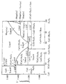
そして、この焼成工程では、混合モル比に応じて、加熱温度の上限を調整する。これにより、図11のCa−Fe−O系の相平衡図に示されるように、混合モル比及び加熱温度に応じて、それぞれ所定の生成物を得ることができる。 And in this baking process, the upper limit of heating temperature is adjusted according to mixing molar ratio. Thereby, as shown in the phase equilibrium diagram of the Ca—Fe—O system in FIG. 11, predetermined products can be obtained in accordance with the mixing molar ratio and the heating temperature.
なお、図11の横軸はCaOとFe2 O3 の重量比を百分率で表したものである。また、図11の横軸において、58の値の近傍にある白丸は、前記混合モル比がCa/Fe=1のときであり、このときにCa2 Fe2 O5 が単相で得られ、また、74の値の近傍にある白丸は、前記混合モル比がCa/Fe=0.5のときであり、このときにCaFe2 O4 が単相で得られ、また、85の値の近傍にある白丸は、前記混合モル比がCa/Fe=0.25のときであり、このときにCaFe4 O7 が単相で得られる。 In addition, the horizontal axis of FIG. 11 represents the weight ratio of CaO and Fe 2 O 3 in percentage. Also, in the horizontal axis of FIG. 11, the white circles near the value of 58 are when the mixing molar ratio is Ca / Fe = 1, and at this time, Ca 2 Fe 2 O 5 is obtained in a single phase, A white circle in the vicinity of the value of 74 is when the mixing molar ratio is Ca / Fe = 0.5. At this time, CaFe 2 O 4 is obtained in a single phase, and in the vicinity of a value of 85. The white circles in the graph are when the mixing molar ratio is Ca / Fe = 0.25, and at this time, CaFe 4 O 7 is obtained in a single phase.
すなわち、前記混合モル比Ca/Feが1.0≦Ca/Feであるときに1438℃以下の加熱温度で加熱したときは、CaO粉末とCa2 Fe2 O5 の組成式を有するカルシウムフェライト粉末とを理論的には得ることができる。また、前記混合モル比が0.5≦Ca/Fe<1であるときに600〜1216℃の加熱温度で加熱したときは、Ca2 Fe2 O5 の組成式を有するカルシウムフェライト粉末とCaFe2 O4 の組成式を有するカルシウムフェライト粉末とを理論的には得ることができる。また、前記混合モル比が0.25≦Ca/Fe<0.5であるときに1155〜1205℃の加熱温度で加熱したときは、CaFe2 O4 の組成式を有するカルシウムフェライト粉末と、CaFe4 O7 の組成式を有するカルシウムフェライト粉末とを理論的には得ることができる。また、前記混合モル比が0<Ca/Fe<0.5であるときに600〜1155℃の加熱温度で焼成したときは、CaFe2 O4 の組成式を有するカルシウムフェライト粉末と、Fe2 O3 (ヘマタイト)粉末とを理論的には得ることができる。また、前記混合モル比が0<Ca/Fe<0.25であるときに1155〜1226℃の加熱温度で焼成したときは、Ca2 Fe2 O5 の組成式を有するカルシウムフェライト粉末と、Fe2 O3 (ヘマタイト)粉末とを理論的には得ることができる。 That is, when the mixed molar ratio Ca / Fe is 1.0 ≦ Ca / Fe, when heated at a heating temperature of 1438 ° C. or lower, the calcium ferrite powder having the composition formula of CaO powder and Ca 2 Fe 2 O 5 Can be obtained theoretically. Further, when the mixing molar ratio is 0.5 ≦ Ca / Fe <1, when heated at a heating temperature of 600 to 1216 ° C., calcium ferrite powder having a composition formula of Ca 2 Fe 2 O 5 and CaFe 2 A calcium ferrite powder having the composition formula of O 4 can be theoretically obtained. Further, when the mixing molar ratio is 0.25 ≦ Ca / Fe <0.5, when heated at a heating temperature of 1155 to 1205 ° C., calcium ferrite powder having a composition formula of CaFe 2 O 4 , and CaFe A calcium ferrite powder having a composition formula of 4 O 7 can be theoretically obtained. Further, when the mixing molar ratio is 0 <Ca / Fe <0.5, when calcined at a heating temperature of 600 to 1155 ° C., calcium ferrite powder having a composition formula of CaFe 2 O 4 and Fe 2 O 3 (hematite) powder can be obtained theoretically. When the mixing molar ratio is 0 <Ca / Fe <0.25, when calcined at a heating temperature of 1155 to 1226 ° C., calcium ferrite powder having a composition formula of Ca 2 Fe 2 O 5 and Fe 2 O 3 (hematite) powder can be theoretically obtained.
なお、前記混合モル比Ca/Feが1.0≦Ca/Feであるときに1438℃以下の加熱温度で加熱した場合に得られるCaO粉末は、原料粉末がそのまま残存したものである。同様に、前記混合モル比が0<Ca/Fe<0.5であるときに600〜1155℃の加熱温度で焼成した場合、及び前記混合モル比が0<Ca/Fe<0.25であるときに1155〜1226℃の加熱温度で焼成した場合に得られるFe2 O3 (ヘマタイト)粉末も、原料粉末がそのまま残存したものである。また、加熱温度の上限が上述した範囲から外れると、液相としてのガラス相ができてしまい、得られる粉末の酸化触媒機能が不十分となる。 The CaO powder obtained when heated at a heating temperature of 1438 ° C. or lower when the mixed molar ratio Ca / Fe is 1.0 ≦ Ca / Fe is such that the raw material powder remains as it is. Similarly, when the mixing molar ratio is 0 <Ca / Fe <0.5, the baking is performed at a heating temperature of 600 to 1155 ° C., and the mixing molar ratio is 0 <Ca / Fe <0.25. Sometimes the Fe 2 O 3 (hematite) powder obtained when calcined at a heating temperature of 1155 to 1226 ° C. is the one in which the raw material powder remains as it is. On the other hand, if the upper limit of the heating temperature is out of the above range, a glass phase is formed as a liquid phase, and the oxidation catalyst function of the obtained powder becomes insufficient.
ここに、本発明の製造方法により得られるCaO粉末、Ca2 Fe2 O5 の組成式を有するカルシウムフェライト粉末、CaFe2 O4 の組成式を有するカルシウムフェライト粉末、CaFe4 O7 の組成式を有するカルシウムフェライト粉末及びFe2 O3 (ヘマタイト)粉末のうちでは、Ca2 Fe2 O5 の組成式を有するカルシウムフェライト粉末が最も高い触媒活性を示し、CaFe2 O4 の組成式を有するカルシウムフェライト粉末がその次に高い触媒活性を示す。このため、少なくともCa2 Fe2 O5 の組成式を有するカルシウムフェライト粉末が得られるような混合モル比及び加熱温度を採用することが好ましい。 Here, the CaO powder obtained by the production method of the present invention, the calcium ferrite powder having the composition formula of Ca 2 Fe 2 O 5 , the calcium ferrite powder having the composition formula of CaFe 2 O 4 , and the composition formula of CaFe 4 O 7 are shown. Among calcium ferrite powders and Fe 2 O 3 (hematite) powders, calcium ferrite powders having the composition formula of Ca 2 Fe 2 O 5 exhibit the highest catalytic activity, and calcium ferrites having the composition formula of CaFe 2 O 4 The powder has the next highest catalytic activity. For this reason, it is preferable to employ a mixing molar ratio and a heating temperature so that a calcium ferrite powder having a composition formula of at least Ca 2 Fe 2 O 5 can be obtained.
また、前記混合モル比の上限は3.0とすることが好ましく、2.0とすることがより好ましく、1.5とすることが特に好ましい。混合モル比が3.0を超えると、CaO粉末とCa2 Fe2 O5 の組成式を有するカルシウムフェライト粉末との混合粉末中に占めるCaO粉末の割合が大きくなりすぎて、触媒活性が低下する。 The upper limit of the mixing molar ratio is preferably 3.0, more preferably 2.0, and particularly preferably 1.5. When the mixing molar ratio exceeds 3.0, the ratio of the CaO powder in the mixed powder of the CaO powder and the calcium ferrite powder having the composition formula of Ca 2 Fe 2 O 5 becomes too large, and the catalytic activity decreases. .
一方、前記混合モル比の下限は、1155℃以下で加熱するときは、0.33とすることが好ましい。1155℃以下で加熱するときに、混合モル比が0.33未満になると、CaFe2 O4 の組成式を有するカルシウムフェライト粉末とFe2 O3 (ヘマタイト)粉末と混合粉末中に占めるFe2 O3 (ヘマタイト)の割合が大きくなりすぎて、触媒活性が低下する。 On the other hand, the lower limit of the mixing molar ratio is preferably 0.33 when heating at 1155 ° C. or lower. When heating at 1155 ° C. or lower, if the mixing molar ratio is less than 0.33, calcium ferrite powder having the composition formula of CaFe 2 O 4 , Fe 2 O 3 (hematite) powder, and Fe 2 O in the mixed powder 3 The ratio of (hematite) becomes too large and the catalytic activity decreases.
また、焼成工程での加熱温度は、上述した所定の範囲内であまり高くしすぎても、それによるメリットはない。このため、Ca2 Fe2 O5 の組成式を有するカルシウムフェライト粉末を少なくとも含む酸化触媒を得る際は、焼成工程での加熱温度の上限を1200℃とすることが好ましく、1000℃とすることがより好ましい。 Further, even if the heating temperature in the firing step is too high within the above-described predetermined range, there is no merit due to it. Therefore, when obtaining at least containing the oxidation catalyst and the calcium ferrite powder having a composition formula of Ca 2 Fe 2 O 5 is preferably that the upper limit of the heating temperature in the firing step and 1200 ° C., be 1000 ° C. More preferred.
こうして得られたそれぞれの混合粉末は、混合粉末を構成する各粉末のそれぞれが酸化触媒機能を発揮する。このため、本発明の製造方法によれば、カルシア源及びフェライト源という貴金属に比べて安価な混合原料を用い、その混合原料を酸素雰囲気で所定温度に加熱するという簡易な方法により、高い触媒活性を示す酸化触媒を得ることができる。しかも、混合原料における混合モル比について、特定の一点をねらって調製する必要がないことから、容易に混合原料を準備することができる。したがって、本発明の製造方法によれば、高い触媒活性を示す酸化触媒を安価かつ容易に得ることが可能となる。 In each of the mixed powders thus obtained, each powder constituting the mixed powder exhibits an oxidation catalyst function. Therefore, according to the production method of the present invention, high catalytic activity is achieved by a simple method of using a mixed raw material cheaper than noble metals such as calcia source and ferrite source and heating the mixed raw material to a predetermined temperature in an oxygen atmosphere. An oxidation catalyst showing can be obtained. And since it is not necessary to prepare for the specific molar point about the mixing molar ratio in a mixed raw material, a mixed raw material can be prepared easily. Therefore, according to the production method of the present invention, it is possible to easily and inexpensively obtain an oxidation catalyst exhibiting high catalytic activity.
本発明の製造方法により得られた排ガス浄化用酸化触媒は、前述した本発明の排ガス浄化用酸化触媒と同様の使用形態に供することができる。 The exhaust gas purifying oxidation catalyst obtained by the production method of the present invention can be used in the same usage form as the exhaust gas purifying oxidation catalyst of the present invention described above.
よって、本発明の排ガス浄化用酸化触媒又は本発明の製造方法により得られた排ガス浄化用酸化触媒は、特に自動二輪車用の排ガス浄化用触媒に好適に利用することができる他、ボイラー等の各種燃焼装置から排出される排ガス浄化用触媒にも好適に利用することができる。 Thus, the exhaust gas purifying oxidation catalyst obtained by the production method of the exhaust gas purifying oxidation catalyst or the invention of the present invention, in addition which can be suitably used in particular an exhaust gas purification catalyst for motorcycles, various boilers and the like It can also be suitably used for an exhaust gas purifying catalyst discharged from a combustion apparatus.
以下、本発明の実施例について具体的に説明する。 Examples of the present invention will be specifically described below.
<混合原料準備工程>
カルシア源としてCaO粉末と、フェライト源としてのFe2 O3 粉末とを準備し、表1に示す所定の混合モル比で混合し、混合原料を得た。なお、CaO粉末及びFe2 O3 粉末は、微粉砕器で予め平均10ミクロンに粒度を揃えておいた。
<Mixed raw material preparation process>
CaO powder as a calcia source and Fe 2 O 3 powder as a ferrite source were prepared and mixed at a predetermined mixing molar ratio shown in Table 1 to obtain a mixed raw material. The CaO powder and the Fe 2 O 3 powder had a particle size of 10 microns on average in advance with a fine grinder.
<焼成工程>
次に、上記混合原料を電気炉に入れ、酸素雰囲気下で室温から1000℃まで約1時間で昇温し、その温度で3時間保持した後、自然放冷してNo.1〜6の触媒試料を得た。
<Baking process>
Next, the mixed raw material was put in an electric furnace, heated from room temperature to 1000 ° C. in an oxygen atmosphere in about 1 hour, held at that temperature for 3 hours, and then allowed to cool naturally. 1-6 catalyst samples were obtained.
なお、得られた触媒試料は外気に触れないよう、プラスチック製試料ビンに入れた保存した。 The obtained catalyst sample was stored in a plastic sample bottle so as not to be exposed to the outside air.

(XRD(結晶相)評価)
触媒試料No.1〜6について、触媒試料中に含まれる結晶相を同定するため、粉末X線回折装置(製品名「RINT−2600TTR」、理学電機社製)を用いて、以下に示す手順により回折パターンを測定した。
(XRD (crystal phase) evaluation)
Catalyst sample No. For 1 to 6, in order to identify the crystal phase contained in the catalyst sample, a diffraction pattern was measured by the following procedure using a powder X-ray diffractometer (product name “RINT-2600TTR”, manufactured by Rigaku Corporation) did.
まず、乳鉢を用いて触媒試料を十分に微細化した。そして、触媒試料を測定用サンプルホルダ(ガラス製、深さ0.2mm)に適量とり、ガラス板を押し付けてセル上の粉体表面を平らにした。このサンプルホルダをX線回折装置にセットし、触媒試料表面にCuKα線(管電圧50kV、管電流100mA)を照射してX線回折パターンを測定した。なお、ゴニオメーターの走査範囲は2θ=10.0〜80.0°、スキャンスピードは1.0°/minとした。また、結晶相の同定はASTM(Ca2 Fe2 O5 :47−1711、CaFe2 O4 :32−0168、Ca(OH)2 :44−1481、Fe2 O3 :33−066)カードを用いて行った。
First, the catalyst sample was sufficiently refined using a mortar. Then, an appropriate amount of the catalyst sample was placed in a measurement sample holder (made of glass, depth 0.2 mm), and a glass plate was pressed to flatten the powder surface on the cell. This sample holder was set in an X-ray diffractometer, and the surface of the catalyst sample was irradiated with CuKα rays (
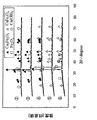
結果を図1に示す。図1中、▲がCa2 Fe2 O5 を示すピークであり、△がCaFe2 O4 を示すピークであり、□がFe2 O3 を示すピークであり、■がCa(OH)2 を示すピークである。なお、X線回折で観察されたCa(OH)2 は、CaOが空気中の水分と反応したものと考えられる。 The results are shown in FIG. In FIG. 1, ▲ is a peak showing Ca 2 Fe 2 O 5 , △ is a peak showing CaFe 2 O 4 , □ is a peak showing Fe 2 O 3 , and ■ is Ca (OH) 2 . It is the peak shown. In addition, it is thought that Ca (OH) 2 observed by X-ray diffraction is a reaction of CaO with moisture in the air.
図1より、前記混合モル比Ca/Feが1.5である試料No.2は、Ca2 Fe2 O5 とCa(OH)2 のピークが確認された。また、Ca/Feが1.0である試料No.3は、Ca2 Fe2 O5 のみのピークが確認された。また、Ca/Feが0.67である試料No.4は、Ca2 Fe2 O5 とCaFe2 O4 のピークが確認された。また、Ca/Feが0.5である試料No.5は、CaFe2 O4 のみのピークが確認された。また、Ca/Feが0.33である試料No.6は、CaFe2 O4 とFe2 O3 のピークが確認された。なお、前記混合モル比Ca/Feが2.0である試料No.1は、試料No.2と同様の結果であったため、図1に示されていない。 From FIG. 1, the sample No. 1 having a mixed molar ratio Ca / Fe of 1.5 was obtained. In No. 2 , peaks of Ca 2 Fe 2 O 5 and Ca (OH) 2 were confirmed. Sample No. with Ca / Fe of 1.0. 3, the peak of only Ca 2 Fe 2 O 5 was confirmed. Sample No. with Ca / Fe of 0.67 was used. In No. 4 , peaks of Ca 2 Fe 2 O 5 and CaFe 2 O 4 were confirmed. Sample No. with a Ca / Fe ratio of 0.5 was used. No. 5 confirmed the peak of only CaFe 2 O 4 . Sample No. with a Ca / Fe of 0.33 was used. No. 6 confirmed the peaks of CaFe 2 O 4 and Fe 2 O 3 . In addition, sample No. whose said mixing molar ratio Ca / Fe is 2.0. 1 is Sample No. Since it was the same result as 2, it is not shown in FIG.
これらの結果は、図11に示すCa−Fe−O系の相平衡図により、理論的に予測できるものと同様であった。 These results were the same as those theoretically predicted from the Ca-Fe-O phase equilibrium diagram shown in FIG.
(比表面積測定)
試料No.1〜6について、以下に示す手順の窒素吸着法による一点法で、U字管型のガラス製セルを使用して、BET比表面積を測定した。
(Specific surface area measurement)
Sample No. About 1-6, the BET specific surface area was measured by the single point method by the nitrogen adsorption method of the procedure shown below using the U-shaped glass cell.
まず、セルの重量を測定後、セルに触媒試料を約0.5g(0.43〜0.46g)入れた。そして、触媒試料を入れたセルに逆止弁付きコネクタを取り付け、脱気ポートに装着し、セル下部からマントルヒータをかぶせた。ヘリウムと窒素の混合ガスをU字管内に流しながら105℃で約20分間加熱し、予め触媒試料に吸着している成分を除去し、同時に混合ガスでセル内をパージした。そして、セルを脱気ポートから取り外し、比表面積測定ポートに装着した。そして、セル内の圧力が0.02Torr以下で飽和するまで脱気した。それから液体窒素によりセルを冷却し、触媒表面に窒素を十分吸着させた。液体窒素からセルを取り出し、ファンによる温風で加熱しながら圧力変化を測定し、脱離した窒素ガス量を算出した。そして、測定後の試料の入ったセル重量と、測定前のセル重量との差から触媒単位重量当たりの窒素脱離量を求め、BET多分子吸着モデルに基づき触媒の比表面積を算出した。 First, after measuring the weight of the cell, about 0.5 g (0.43 to 0.46 g) of a catalyst sample was placed in the cell. And the connector with a non-return valve was attached to the cell which put the catalyst sample, it attached to the deaeration port, and the mantle heater was covered from the cell lower part. While flowing a mixed gas of helium and nitrogen into the U-shaped tube, heating was performed at 105 ° C. for about 20 minutes to remove components previously adsorbed on the catalyst sample, and at the same time, the inside of the cell was purged with the mixed gas. Then, the cell was removed from the deaeration port and attached to the specific surface area measurement port. And it deaerated until the pressure in a cell was saturated at 0.02 Torr or less. Then, the cell was cooled with liquid nitrogen, and nitrogen was sufficiently adsorbed on the catalyst surface. The cell was taken out from the liquid nitrogen, the change in pressure was measured while heating with warm air from a fan, and the amount of desorbed nitrogen gas was calculated. And the nitrogen desorption amount per catalyst unit weight was calculated | required from the difference between the cell weight containing the sample after a measurement, and the cell weight before a measurement, and the specific surface area of the catalyst was computed based on the BET multimolecular adsorption model.
結果を前記表1に示すが、No.1〜6の触媒試料は比表面積が1.4〜5.0m2 /g程度であった。通常の酸化触媒に用いられる白金触媒や代表的な酸化金属触媒であるフェライト(Fe2 O3 )触媒は、比表面積が100〜200m2 /g程度であり、これらと比較して、No.1〜6の触媒試料の比表面積は1〜2桁も小さい値を示した。
The results are shown in Table 1 above. The
(ラマン分光測定)
試料No.3、5の触媒試料について、構造中に含まれる活性酸素の有無及び種類を確認するため、以下に示す手順でラマンスペクトルを測定した。
(Raman spectroscopy measurement)
Sample No. About the catalyst sample of 3 and 5, in order to confirm the presence and kind of active oxygen contained in a structure, the Raman spectrum was measured in the procedure shown below.
まず、乳鉢を用いて触媒試料を十分に微細化した。そして、触媒試料をスライドガラス上に適量とり、カバーガラスを押し付けて粉体表面を平らにした。このスライドガラスをラマン分光分析装置(製品名「NRS−1000」、日本分光社製)にセットし、スリットにより減光したレーザビーム(ビーム径1μmのグリーンレーザ(波長:532nm))を触媒試料粒子に照射してラマンスペクトルを測定した。なお、測定に際し、スペクトルの積算回数は2回、露光時間は1回当たり2分間とした。 First, the catalyst sample was sufficiently refined using a mortar. An appropriate amount of the catalyst sample was taken on a slide glass, and a cover glass was pressed to flatten the powder surface. This slide glass was set in a Raman spectroscopic analyzer (product name “NRS-1000”, manufactured by JASCO Corporation), and a laser beam (green laser with a beam diameter of 1 μm (wavelength: 532 nm)) dimmed by a slit was used as catalyst sample particles. And the Raman spectrum was measured. In the measurement, the spectrum was integrated twice and the exposure time was 2 minutes per time.
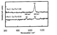
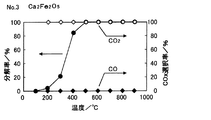
結果を図2に示すように、Ca/Feが1.0であり生成物がCa2 Fe2 O5 である試料No.3は、1093cm-1にラマンシフトが確認され、Ca/Feが0.5であり生成物がCaFe2 O4 である試料No.5は、1022cm-1と、1093cm-1とにラマンシフトが確認された。従来の研究(S.Fujita et al., Chem.Mater., 15, 4879(2003)、L.C.Campelo et al., J.Raman Spectrosc., 10, 33(1981))により、O2 - が1075cm-1付近に、O3 - が1019cm-1付近にスペクトルをもつことが報告されていることから、試料No.3はO2 - の活性酸素、試料No.5はO3 - とO2 - の活性酸素を構造中に内包すると考えられる。 As shown in FIG. 2, sample No. 2 in which Ca / Fe is 1.0 and the product is Ca 2 Fe 2 O 5 is used. 3, sample No. 3 in which Raman shift was confirmed at 1093 cm −1 , Ca / Fe was 0.5, and the product was CaFe 2 O 4 . 5, Raman shift was confirmed at 1022 cm −1 and 1093 cm −1 . According to previous studies (S. Fujita et al., Chem. Mater., 15, 4879 (2003), LCampelo et al., J. Raman Spectrosc., 10, 33 (1981)), O 2 − is 1075 cm −1. Since it has been reported that O 3 − has a spectrum in the vicinity of 1019 cm −1 in the vicinity, sample no. 3 O 2 - active oxygen, Sample No. 5 O 3 - considered active oxygen is contained in the structure of the - and O 2.
(触媒性能評価)
試料No.1〜6について、触媒性能を評価するために、図3に模式構成図を示すガス流通式触媒反応装置を用いて、以下に示す手順で、プロピレン酸化に対する触媒活性を調べた。
(Catalyst performance evaluation)
Sample No. In order to evaluate the catalyst performance of Nos. 1 to 6, the catalytic activity for propylene oxidation was examined by the procedure shown below using a gas flow-type catalytic reactor whose schematic configuration is shown in FIG.
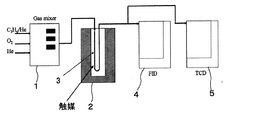
このガス流通式触媒反応装置は、サンプルガスを混合するガスミキサー1と、電気炉2と、電気炉2内で所定温度に加熱される石英ガラス製の反応管3と、FIDガスクロマトグラフ(有機ガス検出用)4と、TCDガスクロマトグラフ(無機ガス検出用)5とを備えている。なお、FIDガスクロマトグラフ4には[Porapak(登録商標) Type Q」を用いた。また、TCDガスクロマトグラフ5には、「Active Carbon、Mesh60/80」をステンレス製カラム(2m)に充填したものを装着した。
This gas flow type catalytic reaction apparatus includes a
なお、この反応装置において、サンプルガスに水蒸気を共存させる場合は、ガスミキサー1の出口に水蒸気供給用のバブラーが取り付けられる。
In this reaction apparatus, when water vapor is allowed to coexist in the sample gas, a water vapor supply bubbler is attached to the outlet of the
また、サンプルガスは、ヘリウムバランスプロピレンガス(C3 H6 :2000ppm)、純酸素ガス、純ヘリウムガスを混合希釈したものを用いた。 The sample gas used was a mixture-diluted helium balanced propylene gas (C 3 H 6 : 2000 ppm), pure oxygen gas, and pure helium gas.
まず、乳鉢を用いて触媒試料を十分に微細化した。そして、触媒試料を反応管3に充填した。反応管3は内径4mm、高さ約150mmのU字形をしており、触媒の充填層高さが10mmとなるように0.083〜0.084g充填した。なお、充填層の上下は適量のロックウールでパッキングした。そして、この反応管3を電気炉2に設置した。充填層温度は、予め充填層横の管壁に取り付けた熱電対により計測し、温度コントローラを用いて制御した。なお、試料粉末により充填層の圧損が異なることから、石けん膜流量計を用いて反応管出口ガスの流量を保証した。サンプルガスの全ガス量は20mリットル/minに調整した。そして、反応管3内に酸素及びヘリウムの混合ガス(O2 :10vol%)を流し、管内をパージした。電気炉2を昇温加熱し、所定温度(〜900℃)に到達した後、サンプルガスにプロピレンガスを加え、反応管3入り口ガスの組成を、C3 H6 :1000ppm、O2 :10%とした。そのまま30分間定常化のため放置してから、触媒性能評価を開始した。
First, the catalyst sample was sufficiently refined using a mortar. Then, the catalyst sample was filled in the
触媒性能評価にあたり、反応管3入り口/出口ガスに含まれるC3 H6 濃度をFIDガスクロマトグラフ4により、CO2 濃度及びCO濃度をTCDガスクロマトグラフ5により測定した。なお、FIDガスクロマトグラフ4及びTCDガスクロマトグラフ5のカラム温度はそれぞれ100℃及び160℃とした。クロマトグラフはインテグレータを用いて記録・解析し、C3 H6 ガス、CO2 ガス及びCOガスの各ピーク面積より各ガス濃度を算出した。
In evaluating the catalyst performance, the C 3 H 6 concentration contained in the inlet / outlet gas of the
そして、以下に定義されるC3 H6 分解率、COX 選択率により、触媒活性を評価した。 The catalytic activity was evaluated based on the C 3 H 6 decomposition rate and CO X selectivity defined below.
(C3 H6 分解率)[%]={1−(反応管出口のC3 H6 濃度)/(反応管入り口のC3 H6 濃度)}×100
(COX 選択率)[%]=[(反応管出口のCOX 濃度)/{(反応管入り口のC3 H6 濃度−反応管出口のC3 H6 濃度)×3}]×100
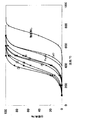
試料No.1〜6について、プロピレン分解率と反応温度との関係を図4に示す。なお、図4中、丸数字の1〜6がそれぞれ試料No.1〜6に対応する。また、比較のため、触媒試料を入れなかった場合のデータと、触媒試料としてCaO、Fe2 O3 を用いた場合のデータも併せて図4に示す。
(C 3 H 6 decomposition rate) [%] = {1- (C 3 H 6 concentration at reaction tube outlet) / (C 3 H 6 concentration at reaction tube inlet)} × 100
(CO X selectivity) [%] = [/ ( CO X concentration of the reaction tube outlet) {(C 3 H 6 concentration in the reaction tube inlet - C 3 H 6 concentration of the reaction tube outlet) × 3}] × 100
Sample No. The relationship between the propylene decomposition rate and the reaction temperature is shown in FIG. In addition, in FIG. Corresponding to 1-6. For comparison, FIG. 4 also shows data when no catalyst sample is added and data when CaO or Fe 2 O 3 is used as the catalyst sample.
Ca2 Fe2 O5 及びCaFe2 O4 のうちの少なくとも一方を含む試料No.1〜6は、いずれも300℃以上で触媒活性を示し、また、いずれも600℃以下で100%の分解率となった。特に、Ca2 Fe2 O5 のみからなる試料No.3は、白金触媒と同等(>200℃)の低温活性を示し、約500℃でプロピレン分解率が100%となった。 Sample No. containing at least one of Ca 2 Fe 2 O 5 and CaFe 2 O 4 Nos. 1 to 6 all showed catalytic activity at 300 ° C. or higher, and all exhibited a decomposition rate of 100% at 600 ° C. or lower. In particular, sample No. consisting of only Ca 2 Fe 2 O 5 . 3 exhibited a low temperature activity equivalent to that of a platinum catalyst (> 200 ° C.), and the propylene decomposition rate became 100% at about 500 ° C.
これらの試料No.1〜6は、前述したように、いずれも比表面積が1.4〜5.0m2 /g程度であり、通常の酸化触媒に用いられる白金触媒やフェライト(Fe2 O3 )触媒の比表面積が100〜200m2 /g程度と比べて、1〜2桁も小さいにもかかわらず、白金触媒と同等又はそれに近い触媒活性を示すことが確認された。 These sample Nos. As described above, 1 to 6 each have a specific surface area of about 1.4 to 5.0 m 2 / g, and a specific surface area of a platinum catalyst or a ferrite (Fe 2 O 3 ) catalyst used for a normal oxidation catalyst. However, it is confirmed that the catalyst activity is equal to or close to that of the platinum catalyst, although it is 1 to 2 orders of magnitude smaller than about 100 to 200 m 2 / g.
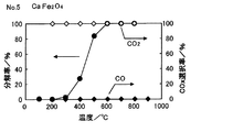
また、試料No.3、5について、プロピレン分解ガスに含まれる生成ガスを分析した。試料No.3の結果を図5に、試料No.5の結果を図6にそれぞれ示す。 Sample No. For 3 and 5, the product gas contained in the propylene cracked gas was analyzed. Sample No. The results of No. 3 are shown in FIG. The results of 5 are shown in FIG.
図5、図6より、プロピレン分解ガスにはCOガスは検出されず、CO2 ガスのみが検出された。 5 and 6, CO gas was not detected in the propylene cracked gas, but only CO 2 gas was detected.
(水蒸気存在下における触媒活性評価)
試料No.3、5について、水蒸気存在下におけるプロピレン酸化に対する触媒活性を調べた。なお、水蒸気の同伴はバブリング装置を用いて室温でガスを飽和し、水蒸気濃度が2.5%となるようにした。
(Evaluation of catalytic activity in the presence of water vapor)
Sample No. 3 and 5 were examined for catalytic activity against propylene oxidation in the presence of water vapor. The entrainment of water vapor was performed by saturating the gas at room temperature using a bubbling device so that the water vapor concentration was 2.5%.
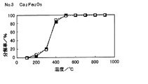
試料No.3についてのプロピレン分解率と反応温度との関係を図7に示し、試料No.5についてのプロピレン分解率と反応温度との関係を図8に示す。なお、図7及び図8中、■と実線で示す分解率が水蒸気存在下の結果で、□と点線で示す分解率が乾燥条件での結果である。 Sample No. 3 shows the relationship between the propylene decomposition rate and the reaction temperature. FIG. 8 shows the relationship between the propylene decomposition rate and reaction temperature for No. 5. 7 and 8, the decomposition rate indicated by ■ and the solid line is the result in the presence of water vapor, and the decomposition rate indicated by □ and the dotted line is the result under dry conditions.
図7及び図8より、試料No.3、5のいずれも、水蒸気の存在により触媒活性が低下しないことが確認された。 From FIG. 7 and FIG. It was confirmed that the catalytic activity of 3 and 5 did not decrease due to the presence of water vapor.
(触媒の耐久性評価)
試料No.3、5について、自動二輪車用の排ガス浄化用触媒としての実用化を想定し、長時間(9時間)の触媒耐久性評価を行った。
(Catalyst durability evaluation)
Sample No. 3 and 5 were evaluated for catalyst durability for a long time (9 hours) assuming practical application as an exhaust gas purification catalyst for motorcycles.
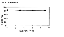
試料No.3についての400℃におけるプロピレン分解率の経時変化を図9に示し、試料No.5についての500℃におけるプロピレン分解率の経時変化を図10に示す。なお、図9及び図10中、■で示す分解率が水蒸気存在下の結果で、○で示す分解率が乾燥条件での結果である。 Sample No. The change with time in the propylene decomposition rate at 400 ° C. for No. 3 is shown in FIG. The time-dependent change of the propylene decomposition rate at 500 ° C. for No. 5 is shown in FIG. 9 and 10, the decomposition rate indicated by ▪ is the result in the presence of water vapor, and the decomposition rate indicated by ◯ is the result under dry conditions.
図9及び図10より、試料No.3、5のいずれも、耐久性が認められ、かつ水蒸気の存在により耐久性が低下しないことが確認された。 From FIG. 9 and FIG. In each of 3 and 5, durability was confirmed, and it was confirmed that the durability was not lowered by the presence of water vapor.
(付記)
なお、カルシア源とフェライト源とを所定の混合モル比Ca/Feで含む混合原料を酸素雰囲気で焼成することにより、酸化触媒として有用なカルシウムフェライトを得ることができるのと同様に、A元素(アルカリ又はアルカリ土類)とB元素(遷移元素)とを所定の混合モル比A/Bで含む混合原料を酸素雰囲気で焼成することによっても、酸化触媒として有用なAX BY OZ 化合物を得ることができるものと考えられる。
(Appendix)
In addition, by calcining a mixed raw material containing a calcia source and a ferrite source at a predetermined mixing molar ratio Ca / Fe in an oxygen atmosphere, calcium ferrite useful as an oxidation catalyst can be obtained as well as element A ( An A X B Y O Z compound useful as an oxidation catalyst can also be obtained by firing a mixed raw material containing an alkali or alkaline earth) and B element (transition element) at a predetermined mixing molar ratio A / B in an oxygen atmosphere. It is thought that it can be obtained.
1…ガスミキサー 2…電気炉
3…反応管 4…FIDガスクロマトグラフ
5…TCDガスクロマトグラフ
DESCRIPTION OF
Claims (5)
前記焼成工程では、前記混合モル比Ca/Feが、1.0≦Ca/Feであるときは1438℃以下の加熱温度で、0.5≦Ca/Fe<1であるときは1216℃以下の加熱温度で、0.25≦Ca/Fe<0.5であるときは1205℃以下の加熱温度で、0<Ca/Fe<0.25であるときは1226℃以下の加熱温度で、それぞれ加熱することにより、活性酸素を構造中に内包したCa2Fe2O5の組成式を有するカルシウムフェライト及び活性酸素を構造中に内包したCaFe2O4の組成式を有するカルシウムフェライトのうちの少なくとも一種を含む酸化触媒を製造することを特徴とする排ガス浄化用酸化触媒の製造方法。 A mixed raw material preparation step for obtaining a mixed raw material containing a calcia source and a ferrite source at a predetermined mixing molar ratio Ca / Fe, and a firing step for heating the mixed raw material to 600 ° C. or higher in an oxygen atmosphere,
In the firing step, when the mixed molar ratio Ca / Fe is 1.0 ≦ Ca / Fe, the heating temperature is 1438 ° C. or lower, and when 0.5 ≦ Ca / Fe <1, the lower temperature is 1216 ° C. When the heating temperature is 0.25 ≦ Ca / Fe <0.5, the heating temperature is 1205 ° C. or less, and when 0 <Ca / Fe <0.25, the heating temperature is 1226 ° C. or less. By doing so, at least one of calcium ferrite having a composition formula of Ca 2 Fe 2 O 5 encapsulating active oxygen in the structure and calcium ferrite having a composition formula of CaFe 2 O 4 encapsulating active oxygen in the structure A method for producing an exhaust gas purifying oxidation catalyst, comprising producing an oxidation catalyst comprising:
Priority Applications (1)
| Application Number | Priority Date | Filing Date | Title |
|---|---|---|---|
| JP2005080679A JP4635197B2 (en) | 2005-03-18 | 2005-03-18 | Oxidation catalyst for exhaust gas purification and method for producing the same |
Applications Claiming Priority (1)
| Application Number | Priority Date | Filing Date | Title |
|---|---|---|---|
| JP2005080679A JP4635197B2 (en) | 2005-03-18 | 2005-03-18 | Oxidation catalyst for exhaust gas purification and method for producing the same |
Publications (2)
| Publication Number | Publication Date |
|---|---|
| JP2006255677A JP2006255677A (en) | 2006-09-28 |
| JP4635197B2 true JP4635197B2 (en) | 2011-02-16 |
Family
ID=37095459
Family Applications (1)
| Application Number | Title | Priority Date | Filing Date |
|---|---|---|---|
| JP2005080679A Expired - Lifetime JP4635197B2 (en) | 2005-03-18 | 2005-03-18 | Oxidation catalyst for exhaust gas purification and method for producing the same |
Country Status (1)
| Country | Link |
|---|---|
| JP (1) | JP4635197B2 (en) |
Cited By (1)
| Publication number | Priority date | Publication date | Assignee | Title |
|---|---|---|---|---|
| CN111841296A (en) * | 2020-07-27 | 2020-10-30 | 北京北科环境工程有限公司 | Desulfurizing agent for blast furnace gas and preparation method thereof |
Families Citing this family (14)
| Publication number | Priority date | Publication date | Assignee | Title |
|---|---|---|---|---|
| JP2009012156A (en) * | 2007-07-09 | 2009-01-22 | Yamanashi Prefecture | Peening method |
| JP2009142789A (en) * | 2007-12-17 | 2009-07-02 | Nippon Steel Materials Co Ltd | Exhaust gas purification catalyst carrier and manufacturing method thereof, exhaust gas purification catalyst, and exhaust gas purification honeycomb catalyst structure |
| JP5009777B2 (en) * | 2007-12-28 | 2012-08-22 | ラボテック株式会社 | Method for producing hybrid combustion catalyst |
| JPWO2010010714A1 (en) * | 2008-07-23 | 2012-01-05 | 新日鉄マテリアルズ株式会社 | Oxygen storage material, exhaust gas purification catalyst, and honeycomb catalyst structure for exhaust gas purification |
| WO2010103669A1 (en) * | 2009-03-12 | 2010-09-16 | 新日鉄マテリアルズ株式会社 | Catalyst carrier for exhaust gas purification, process for production thereof, exhaust gas purification catalyst, and honeycomb catalyst structure for exhaust gas purification |
| JP2010284597A (en) * | 2009-06-12 | 2010-12-24 | Nippon Steel Materials Co Ltd | Diesel exhaust gas oxidation catalyst and diesel exhaust gas oxidation catalyst honeycomb structure |
| JP5704047B2 (en) * | 2011-10-12 | 2015-04-22 | トヨタ自動車株式会社 | Exhaust gas purification catalyst |
| JP5760981B2 (en) * | 2011-11-25 | 2015-08-12 | トヨタ自動車株式会社 | Exhaust gas purification catalyst and method for producing the same |
| JP5720558B2 (en) * | 2011-12-15 | 2015-05-20 | トヨタ自動車株式会社 | Exhaust gas purification catalyst |
| JP2013194572A (en) * | 2012-03-16 | 2013-09-30 | Osaka Gas Co Ltd | Exhaust emission control device for engine |
| JP2018059480A (en) * | 2016-10-07 | 2018-04-12 | 國立高雄應用科技大學 | Use using ferrite as three-way catalyst for treating automobile engine exhaust gas |
| CN107601430B (en) * | 2017-09-25 | 2020-09-15 | 东南大学 | Method and device for synergistic capture of carbon dioxide based on CaFe2O4/Ca2Fe2O5 catalytic cycle for hydrogen production |
| RU2729783C1 (en) * | 2020-02-18 | 2020-08-12 | Федеральное государственное бюджетное научное учреждение "Федеральный исследовательский центр "Красноярский научный центр Сибирского отделения Российской академии наук" (ФИЦ КНЦ СО РАН, КНЦ СО РАН) | METHOD OF PRODUCING MATERIAL HAVING GAS-SENSITIVE AND CATALYTIC PROPERTIES, BASED ON CaFe2O4 |
| CN114229910A (en) * | 2021-11-08 | 2022-03-25 | 宁夏大学 | Calcium-iron dual-function composite oxygen carrier and large-scale preparation method thereof |
Family Cites Families (4)
| Publication number | Priority date | Publication date | Assignee | Title |
|---|---|---|---|---|
| JPS513128B2 (en) * | 1971-08-25 | 1976-01-31 | ||
| JPS5021988A (en) * | 1973-06-29 | 1975-03-08 | ||
| JPS5230275B2 (en) * | 1974-03-06 | 1977-08-06 | ||
| JP4281061B2 (en) * | 2004-04-15 | 2009-06-17 | 独立行政法人産業技術総合研究所 | Active oxygen storage material and method for producing the same |
-
2005
- 2005-03-18 JP JP2005080679A patent/JP4635197B2/en not_active Expired - Lifetime
Cited By (1)
| Publication number | Priority date | Publication date | Assignee | Title |
|---|---|---|---|---|
| CN111841296A (en) * | 2020-07-27 | 2020-10-30 | 北京北科环境工程有限公司 | Desulfurizing agent for blast furnace gas and preparation method thereof |
Also Published As
| Publication number | Publication date |
|---|---|
| JP2006255677A (en) | 2006-09-28 |
Similar Documents
| Publication | Publication Date | Title |
|---|---|---|
| JP4635197B2 (en) | Oxidation catalyst for exhaust gas purification and method for producing the same | |
| Zhang et al. | The catalytic oxidation performance of toluene over the Ce-Mn-Ox catalysts: Effect of synthetic routes | |
| Dasireddy et al. | Selective catalytic reduction of NOx by CO over bimetallic transition metals supported by multi-walled carbon nanotubes (MWCNT) | |
| JP6143761B2 (en) | Hydrogen production catalyst and method for producing hydrogen | |
| Li et al. | Influence of zirconia crystal phase on the catalytic performance of Au/ZrO2 catalysts for low-temperature water gas shift reaction | |
| Song et al. | Influence of the precursor on the porous structure and CO 2 adsorption characteristics of MgO | |
| Saeidi et al. | Co-doping a metal (Cr, Mn, Fe, Co, Ni, Cu, and Zn) on Mn/ZSM-5 catalyst and its effect on the catalytic reduction of nitrogen oxides with ammonia | |
| Yuan et al. | Liquid‐phase hydrogenation of cinnamaldehyde over Cu‐Au/SiO2 catalysts | |
| Liu et al. | Tiny Ni particles dispersed in platelet SBA-15 materials induce high efficiency for CO 2 methanation | |
| Yang et al. | Combined effect of oxygen vacancies and mesopore sizes in ZnO/SiO2 adsorbents on boosting the H2S removal efficiency in moist conditions | |
| Ruszak et al. | Selective N2O removal from the process gas of nitric acid plants over ceramic 12CaO· 7Al2O3 catalyst | |
| Richards et al. | Effect of the preparation method of LaSrCoFeOx perovskites on the activity of N2O decomposition | |
| Zhang et al. | Enhancement of catalytic performance over different transition metals modified CeO2 for toluene abatement | |
| Deng et al. | Preparation, characterization, and catalytic properties of NdSrCu1− xCoxO4− δ and Sm1. 8Ce0. 2Cu1− xCoxO4+ δ (x= 0, 0.2 and 0.4) for methane combustion | |
| Rotko | The use of 18O2 to investigate the soot oxidation process on Co3O4, Co3O4-CeO2 and CeO2 catalysts in tight contact conditions | |
| Li et al. | Effect of La-modified supporter on H2S removal performance of Mn/La/Al2O3 sorbent in a reducing atmosphere | |
| Sun et al. | Fabrication of Pd 3@ Beta for catalytic combustion of VOCs by efficient Pd 3 cluster and seed-directed hydrothermal syntheses | |
| JP4625952B2 (en) | Method for producing oxidation catalyst | |
| Hanif et al. | Sulfur dioxide removal by calcium-modified fibrous KCC-1 mesoporous silica: kinetics, thermodynamics, isotherm and mass transfer mechanism | |
| Qi et al. | Catalytic oxidation of toluene over B‐site doped La‐based perovskite LaNi x B1− x O3 (B= Co, Cu) catalysts | |
| Cheng et al. | Effect of ceria loading on Zr-pillared clay catalysts for selective catalytic reduction of NO with NH 3 | |
| Zhu et al. | Insights into the active sites of copper species in CuO/SiO2 catalysts for NH3-SCR: Quantitative analysis and mechanism study | |
| US20070134144A1 (en) | Gold- and reducible oxide-based composition, method for the preparation and the use thereof in the form of a catalyst, in particular for carbon monoxide oxidation | |
| Levasseur et al. | Interactions of NO2 at ambient temperature with cerium–zirconium mixed oxides supported on SBA-15 | |
| CN113891762A (en) | Beta-zeolite and catalyst containing same |
Legal Events
| Date | Code | Title | Description |
|---|---|---|---|
| A621 | Written request for application examination |
Free format text: JAPANESE INTERMEDIATE CODE: A621 Effective date: 20080303 |
|
| A977 | Report on retrieval |
Free format text: JAPANESE INTERMEDIATE CODE: A971007 Effective date: 20100707 |
|
| A131 | Notification of reasons for refusal |
Free format text: JAPANESE INTERMEDIATE CODE: A131 Effective date: 20100713 |
|
| A521 | Request for written amendment filed |
Free format text: JAPANESE INTERMEDIATE CODE: A523 Effective date: 20100908 |
|
| A131 | Notification of reasons for refusal |
Free format text: JAPANESE INTERMEDIATE CODE: A131 Effective date: 20100930 |
|
| A521 | Request for written amendment filed |
Free format text: JAPANESE INTERMEDIATE CODE: A523 Effective date: 20101006 |
|
| TRDD | Decision of grant or rejection written | ||
| A01 | Written decision to grant a patent or to grant a registration (utility model) |
Free format text: JAPANESE INTERMEDIATE CODE: A01 Effective date: 20101026 |
|
| A01 | Written decision to grant a patent or to grant a registration (utility model) |
Free format text: JAPANESE INTERMEDIATE CODE: A01 |
|
| R150 | Certificate of patent or registration of utility model |
Ref document number: 4635197 Country of ref document: JP Free format text: JAPANESE INTERMEDIATE CODE: R150 Free format text: JAPANESE INTERMEDIATE CODE: R150 |
|
| S533 | Written request for registration of change of name |
Free format text: JAPANESE INTERMEDIATE CODE: R313533 |
|
| R350 | Written notification of registration of transfer |
Free format text: JAPANESE INTERMEDIATE CODE: R350 |
|
| EXPY | Cancellation because of completion of term |