JP4635186B2 - Material integrity evaluation system - Google Patents
Material integrity evaluation system Download PDFInfo
- Publication number
- JP4635186B2 JP4635186B2 JP2006066290A JP2006066290A JP4635186B2 JP 4635186 B2 JP4635186 B2 JP 4635186B2 JP 2006066290 A JP2006066290 A JP 2006066290A JP 2006066290 A JP2006066290 A JP 2006066290A JP 4635186 B2 JP4635186 B2 JP 4635186B2
- Authority
- JP
- Japan
- Prior art keywords
- ultrasonic
- subject
- optical fiber
- guide optical
- piezoelectric
- Prior art date
- Legal status (The legal status is an assumption and is not a legal conclusion. Google has not performed a legal analysis and makes no representation as to the accuracy of the status listed.)
- Expired - Fee Related
Links
Images


Landscapes
- Investigating Or Analyzing Materials By The Use Of Ultrasonic Waves (AREA)
Description
本発明は、光ファイバを超音波伝搬路として利用する材料健全性評価装置に関するものである。 The present invention relates to a material soundness evaluation apparatus using an optical fiber as an ultrasonic wave propagation path.
構造物の欠陥検出、損傷発生監視などに超音波を利用した非破壊検査が行われている。従来、超音波を利用した構造体の非破壊検査は超音波を被検体に発生させる手段として次の三つの手段が用いられている。 Nondestructive inspection using ultrasonic waves is performed for detecting defects in structures and monitoring damage occurrence. Conventionally, in the nondestructive inspection of a structure using ultrasonic waves, the following three means are used as means for generating ultrasonic waves in a subject.
(1)圧電超音波発振子
この圧電超音波発振子は、超音波発振子には圧電素子が用いられているものであり、被検体内部、または表面に取り付けられて用いられるものである(特許文献1参照)。この手段は、圧電超音波発振子に電気信号を与えた場合、圧電効果によりその信号に対応した変位が発生し、圧電素子を取り付けた被検体に超音波が発生する。
(1) Piezoelectric ultrasonic oscillator This piezoelectric ultrasonic oscillator uses a piezoelectric element for the ultrasonic oscillator, and is used by being attached to the inside of a subject or on the surface (patent) Reference 1). In this means, when an electrical signal is given to the piezoelectric ultrasonic oscillator, a displacement corresponding to the signal is generated due to the piezoelectric effect, and an ultrasonic wave is generated in the subject to which the piezoelectric element is attached.
超音波発振子には任意の超音波励起信号を入力することができることから、発振超音波の周波数、波形を制御することができる。このため圧電素子を用いる超音波励起方式では多様な波形の超音波を発生させることができる。 Since an arbitrary ultrasonic excitation signal can be input to the ultrasonic oscillator, the frequency and waveform of the oscillating ultrasonic wave can be controlled. For this reason, ultrasonic waves using a piezoelectric element can generate ultrasonic waves having various waveforms.
(2)レーザを用いる超音波発生手段
この超音波発生手段は、レーザなどを用いて被検体にスポット状の熱源を発生させ、それによって超音波を発生させる手段である(特許文献2参照)。レーザを用いる超音波発生手段では、被検体と非接触で超音波を励起することができるため高温環境下において、かつ被検体の形状に関係なく超音波を発生することができる。
(2) Ultrasonic wave generating means using laser This ultrasonic wave generating means is means for generating a spot-like heat source on a subject using a laser or the like, thereby generating ultrasonic waves (see Patent Document 2). Since the ultrasonic wave generation means using a laser can excite the ultrasonic wave in a non-contact manner with the subject, the ultrasonic wave can be generated in a high temperature environment and irrespective of the shape of the subject.
(3)EMAT(ElectroMagnetic Acoustic Transducer)
EMATは、電磁誘導を利用して被検体に超音波を発生させるを用いる手段である(特許文献3参照)。
EMAT is a means that uses an electromagnetic induction to generate ultrasonic waves in a subject (see Patent Document 3).
上記圧電超音波素子は、圧電機能を有さなくなる限界温度(キュリー温度の半分程度で、大半の圧電素子の限界温度は180℃程度)があり、被検体が限界温度を越える高温環境下においては超音波を発振することができない。また圧電素子は形状の柔軟性が乏しいことから圧電素子を取り付けることが困難な複雑形状の被検体への超音波発振はできない。 The piezoelectric ultrasonic element has a limit temperature (about half of the Curie temperature, and the limit temperature of most piezoelectric elements is about 180 ° C.) that does not have a piezoelectric function, and in a high temperature environment where the subject exceeds the limit temperature. Cannot oscillate ultrasonic waves. In addition, since the piezoelectric element has poor shape flexibility, it is not possible to oscillate ultrasonic waves to a subject having a complicated shape in which it is difficult to attach the piezoelectric element.
上記レーザを用いる超音波発生手段ではパルスレーザを照射して超音波を発生させるため、パルス信号で励起された超音波しか発生することができない。このため発振させる超音波の周波数や波形を制御することができず、欠陥がもたらす超音波応答の周波数依存性を利用した非破壊検査手法を適用することができない。 In the ultrasonic wave generation means using the laser, since the ultrasonic wave is generated by irradiating the pulse laser, only the ultrasonic wave excited by the pulse signal can be generated. For this reason, the frequency and waveform of the ultrasonic wave to be oscillated cannot be controlled, and the nondestructive inspection method using the frequency dependence of the ultrasonic response caused by the defect cannot be applied.
EMATを利用した超音波発振手段は、非接触、かつ発振させる超音波の周波数や波形を制御できる利点があるが、超音波を発振させる被検体が磁性材料のみに限られる。近年、比剛性・比強度が高いことから航空・宇宙構造物への適用が拡がっている繊維強化プラスティックスへの超音波発振にEMATを利用することはできない。 Ultrasonic oscillation means using EMAT has the advantage of being able to control the frequency and waveform of ultrasonic waves to be oscillated in a non-contact manner, but the subject that oscillates ultrasonic waves is limited to only magnetic materials. In recent years, EMAT cannot be used for ultrasonic oscillation of fiber-reinforced plastics that have been applied to aerospace structures because of its high specific rigidity and specific strength.
以上、従来の超音波発振手段に関する問題点を述べたが、超音波受信においても接触型の場合、圧電素子の使用限界温度では超音波の受信が出来ない。非接触の場合、レーザ干渉法を利用して超音波を受信することができるが装置が高価なことや振動を最小限に抑える必要があること、被検体の表面が鏡面であることなどの制限があり、実用的には多くの制限がある。またEMATにおいては超音波発振と同様に被検体が磁性材料である制限を受ける。 As described above, the problems related to the conventional ultrasonic oscillating means have been described. However, in the case of the contact type in ultrasonic reception, ultrasonic waves cannot be received at the use limit temperature of the piezoelectric element. In the case of non-contact, it is possible to receive ultrasonic waves using laser interferometry, but there are limitations such as expensive equipment, the need to minimize vibration, and the surface of the subject being a mirror surface. There are many limitations in practical use. In EMAT, the subject is restricted to be a magnetic material as in the case of ultrasonic oscillation.
近年、電磁波障害を受けない光ファイバセンサを利用して構造体の健全性を評価する技術が注目されている。中でもFBG(ファイバ・ブラッグ・グレーティング)センサは高感度に超音波検出が可能なことから超音波を利用した健全性評価システムに適用するセンサとして期待されている。 In recent years, a technique for evaluating the soundness of a structure using an optical fiber sensor that is not affected by electromagnetic interference has attracted attention. Among them, the FBG (fiber Bragg grating) sensor is expected as a sensor to be applied to a soundness evaluation system using ultrasonic waves because it can detect ultrasonic waves with high sensitivity.
FBGセンサは、光ファイバ軸方向に強い超音波検出指向性があり、光ファイバ軸方向に対して垂直方向から伝搬してくる超音波に対しての検出感度は低い。またFBGの反射率は500℃を超える高温で時間とともに低下し、センサとしての機能を果たさなくなる問題がある。 The FBG sensor has a strong ultrasonic detection directivity in the optical fiber axis direction, and has low detection sensitivity for ultrasonic waves propagating from a direction perpendicular to the optical fiber axis direction. Further, the reflectance of FBG decreases with time at a high temperature exceeding 500 ° C., and there is a problem that the function as a sensor cannot be performed.
また、FBGを用いた超音波及びAE検出において、FBGを被検体内部に埋め込む、または表面に貼り付けた場合、被検体が受けるひずみ、または温度変化に応じてFBGの反射波長が変動する。FBGを用いた超音波検出においては検出感度を高めるため、超音波及びAE検出システムとしてレーザ光源を用いた場合、レーザ発振波長を常にFBGの反射率が半減する波長に設定する必要がある。 In addition, in the ultrasonic wave and AE detection using the FBG, when the FBG is embedded in the subject or attached to the surface, the reflection wavelength of the FBG varies according to the strain received by the subject or a temperature change. In order to increase detection sensitivity in ultrasonic detection using the FBG, when a laser light source is used as the ultrasonic and AE detection system, it is necessary to always set the laser oscillation wavelength to a wavelength at which the reflectance of the FBG is halved.
また、広帯域光源とフィルタとの組合せによる超音波及びAE検出システムを用いた場合はFBGのブラッグ波長に合わせて常に検出感度が最大になるようにフィルタ動作点を変動させる必要がある。 In addition, when an ultrasonic and AE detection system using a combination of a broadband light source and a filter is used, it is necessary to change the filter operating point so that the detection sensitivity is always maximized according to the Bragg wavelength of the FBG.
本発明は、上記従来の超音波を利用した構造体の非破壊検査の問題点を解決することを目的とする光ファイバを超音波伝搬路として利用する材料健全性評価装置を実現するものである。 The present invention realizes a material soundness evaluation apparatus that uses an optical fiber as an ultrasonic propagation path for the purpose of solving the above-described problems of non-destructive inspection of a structure using ultrasonic waves. .
本発明は上記課題を解決するために、圧電超音波発振子と、該圧電超音波発振子に一端が取り付けられた超音波ガイド光ファイバと、被検体に伝達された超音波の伝搬状況を測定する測定手段とから成る材料健全性評価装置であって、前記圧電超音波発振子は、発生した超音波を上記超音波ガイド光ファイバに伝達させ、該超音波ガイド光ファイバは、その一部が健全性評価対象となる被検体の内部または表面に取り付けられ、前記超音波は被検体に伝達するものであり、前記測定手段は、前記超音波の伝搬状況により被検体中の欠陥の存在の有無を検査可能とすることを特徴とする材料健全性評価装置を提供する。 In order to solve the above-mentioned problems, the present invention measures the propagation state of a piezoelectric ultrasonic oscillator, an ultrasonic guide optical fiber having one end attached to the piezoelectric ultrasonic oscillator, and the ultrasonic wave transmitted to the subject. The piezoelectric ultrasonic oscillator transmits the generated ultrasonic wave to the ultrasonic guide optical fiber, and the ultrasonic guide optical fiber is a part of the ultrasonic device. The ultrasonic wave is attached to the inside or the surface of the subject to be evaluated for soundness, and the ultrasonic wave is transmitted to the subject. The measurement means determines whether there is a defect in the subject depending on the propagation state of the ultrasonic wave. It is possible to provide a material soundness evaluation apparatus characterized by enabling inspection.
前記超音波ガイド光ファイバは、前記した被検体への超音波送信に加えて被検体からの超音波、またはAEを受信する機能を有し、前記被検体を伝搬する超音波、またはAEを超音波ガイド光ファイバに伝搬させ、前記測定手段は、前記被検体への超音波送信に加えて、被検体の超音波、またはAEの伝搬状況により被検体中の欠陥の存在の有無を検査可能とすることが好ましい。 The ultrasonic guide optical fiber has a function of receiving ultrasonic waves or AE from the subject in addition to transmitting ultrasonic waves to the subject as described above, and transmitting ultrasonic waves or AE that propagate through the subject. Propagating to a sonic guide optical fiber, the measurement means can inspect for the presence of defects in the subject according to the ultrasonic wave of the subject or the propagation status of the AE in addition to the transmission of the ultrasonic wave to the subject. It is preferable to do.
前記超音波ガイド光ファイバには、圧電超音波センサが取り付けられている構成とすることが好ましい。 It is preferable that a piezoelectric ultrasonic sensor is attached to the ultrasonic guide optical fiber.
前記超音波ガイド光ファイバは、その一部にFBGが形成され、該FBGは、前記超音波で生じる反射波長変動を生じさせる構成とすることが好ましい。 It is preferable that the ultrasonic guide optical fiber has an FBG formed in a part thereof, and the FBG is configured to cause a reflection wavelength variation generated by the ultrasonic wave.
前記超音波ガイド光ファイバにおけるFBGを設けた領域は、中空容器で囲まれており、該中空容器を密閉するために用いるカップラントを介して、前記被検体を伝搬する超音波及びAEが前記超音波ガイド光ファイバに伝えられる構成とすることが好ましい。 The region where the FBG is provided in the ultrasonic guide optical fiber is surrounded by a hollow container, and the ultrasonic wave and AE propagating through the subject are transmitted through the coupling used for sealing the hollow container. It is preferable to adopt a configuration that is transmitted to the sonic guide optical fiber.
前記超音波ガイド光ファイバにおけるFBGが形成された領域が前記被検体と同じ雰囲気内に配置されてブラッグ波長を計測することで、該被検体の置かれた雰囲気温度を測定可能とする構成とすることが好ましい。 The region where the FBG is formed in the ultrasonic guide optical fiber is arranged in the same atmosphere as the subject, and the Bragg wavelength is measured so that the ambient temperature where the subject is placed can be measured. It is preferable.
前記超音波ガイド光ファイバは複数本設けられており、該複数本の超音波ガイド光ファイバは、被検体に複数の異なる方向で被検体に取り付けられ、超音波及びAEの検出の指向性を広げる構成とされており、前記圧電超音波センサ又は前記FBGは、複数本の超音波ガイド光ファイバにそれぞれ取り付ける、または設けられている構成、若しくは複数本の超音波ガイド光ファイバの他端がカップラントにより一つにまとめられ取り付ける、または設けられている構成とすることが好ましい。 A plurality of the ultrasonic guide optical fibers are provided, and the plurality of ultrasonic guide optical fibers are attached to the subject in a plurality of different directions with respect to the subject to widen the directivity of detection of ultrasonic waves and AEs. The piezoelectric ultrasonic sensor or the FBG is attached to or provided on a plurality of ultrasonic guide optical fibers, or the other end of the ultrasonic guide optical fibers is a coupling agent. It is preferable to adopt a configuration in which they are assembled together or attached or provided.
前記超音波ガイド光ファイバは、被検体よりも超音波音速の低い材質からなる取付け具に超音波ガイド光ファイバを円形状に取り付けることにより、超音波及びAE検出の指向性を全方位に広げる構成とすることが好ましい。 The ultrasonic guide optical fiber is configured to expand the directivity of ultrasonic and AE detection in all directions by attaching the ultrasonic guide optical fiber in a circular shape to a fixture made of a material having a lower ultrasonic sound velocity than the subject. It is preferable that
前記被検体に取り付けられた複数の超音波ガイド光ファイバは、それぞれAE到達時間を検出し、該AE到達時間差から欠陥発生箇所を標定される構成とすることが好ましい。 It is preferable that the plurality of ultrasonic guide optical fibers attached to the subject each detect an AE arrival time and determine a defect occurrence location from the difference in the AE arrival times.
前記超音波ガイド光ファイバに加えて、前記被検体に取り付けられる超音波送受信ガイド光ファイバが設けられており、該超音波送受信ガイド光ファイバの超音波伝搬状況を前記測定手段で測定することにより、被検体の健全性を評価する構成とすることが好ましい。 In addition to the ultrasonic guide optical fiber, an ultrasonic transmission / reception guide optical fiber attached to the subject is provided, and by measuring the ultrasonic propagation state of the ultrasonic transmission / reception guide optical fiber with the measurement means, A configuration for evaluating the soundness of the subject is preferable.
前記超音波は、レーザまたはEMATを超音波励起源として発生させられる構成とすることが好ましい。 It is preferable that the ultrasonic wave is generated by using a laser or EMAT as an ultrasonic excitation source.
本発明は上記解決手段から成る本発明によれば、次のような効果が生じる。
(1)本発明では、光ファイバを超音波ガイド(伝送路)として利用し、圧電素子から発振させた超音波を光ファイバを介して被検体に伝搬させ、また、被検体を伝搬する超音波及びAEを被検体に取り付けた光ファイバに伝搬させる。
According to the present invention comprising the above solution, the following effects are produced.
(1) In the present invention, an optical fiber is used as an ultrasonic guide (transmission path), an ultrasonic wave oscillated from a piezoelectric element is propagated to the subject via the optical fiber, and an ultrasonic wave propagates through the subject. And AE is propagated to the optical fiber attached to the subject.
このように、光ファイバを超音波ガイドとして利用することにより、被検体の材質、温度、形状に関わらず被検体に超音波を発生させることが出来る、または被検体を伝搬する超音波及びAEを検出することができる。この技術は超音波及びAEを利用した被検体の健全性評価に利用することができる。 In this way, by using an optical fiber as an ultrasonic guide, an ultrasonic wave can be generated in the subject regardless of the material, temperature, and shape of the subject, or ultrasonic waves and AEs that propagate through the subject. Can be detected. This technique can be used to evaluate the soundness of a subject using ultrasound and AE.
(2)複数の方向の異なる超音波ガイド光ファイバを被検体に取り付けることにより超音波及びAE検出の指向性を広げることができる。そのとき超音波ガイド光ファイバを接着剤、接着テープ、またはグリースをカップラントとして用い、接触させることによりそれぞれの超音波ガイド光ファイバに伝搬する超音波及びAEを合成させることができ、一個の超音波センサにより指向性を広げて超音波及びAEを検出することができる。 (2) Directivity of ultrasonic and AE detection can be expanded by attaching a plurality of ultrasonic guide optical fibers having different directions to the subject. At that time, the ultrasonic guide optical fiber can be combined with the ultrasonic wave and the AE propagating to the respective ultrasonic guide optical fibers by using an adhesive, an adhesive tape, or grease as a coupling agent and bringing them into contact with each other. Ultrasonic waves and AE can be detected by expanding the directivity by the acoustic wave sensor.
(3)また、被検体よりも超音波音速の低い材質からなる取付け具に超音波ガイド光ファイバをループ状に取り付けて、その取付け具を被検体に接触させると被検体を伝搬する全方向の超音波及びAEを超音波ガイド光ファイバに伝達させることができる。 (3) Further, when an ultrasonic guide optical fiber is attached in a loop shape to a fixture made of a material having a lower ultrasonic sound velocity than the subject, and the fixture is brought into contact with the subject, the omnidirectional propagation of the subject is achieved. Ultrasound and AE can be transmitted to the ultrasound guide optical fiber.
(4)また、被検体に直接FBGを接触させないことからFBGのセンサとしての機能を失うような高温においても被検体を伝搬する超音波及びAEを検出することができる。 (4) Further, since the FBG is not brought into direct contact with the subject, it is possible to detect ultrasonic waves and AE that propagate through the subject even at a high temperature at which the function of the FBG sensor is lost.
(5)また、FBGを被検体に接触させずに超音波及びAE検出が可能なことから、FBGの反射特性が被検体の温度、ひずみに影響されない。このため、FBG超音波検出システムのレーザ発振波長やフィルタ動作点補正を行うことなく、超音波及びAE検出感度を最大に保った状態で超音波及びAEを検出することができる。 (5) Since the ultrasonic waves and AE can be detected without bringing the FBG into contact with the subject, the reflection characteristics of the FBG are not affected by the temperature and strain of the subject. For this reason, it is possible to detect ultrasonic waves and AE while maintaining the maximum ultrasonic wave and AE detection sensitivity without correcting the laser oscillation wavelength and the filter operating point of the FBG ultrasonic detection system.
本発明に係る材料健全性評価装置の実施の形態を実施例に基づいて図面を参照して、以下に説明する。 DESCRIPTION OF EMBODIMENTS Embodiments of a material soundness evaluation apparatus according to the present invention will be described below with reference to the drawings based on examples.
超音波ガイド光ファイバ2を利用した超音波送受信装置1の実施例1を図1に示す。超音波ガイド光ファイバ2は接着剤、接着テープ、またはグリースなどをカップラント3として圧電超音波発振子4と被検体5に取り付けられている。このとき超音波ガイド光ファイバ2は被検体5の内部に埋め込まれていても同様の機能を果たすことができる。
FIG. 1 shows a first embodiment of an ultrasonic transmission /
圧電超音波発振子4には、信号発生器6から超音波励起信号が入力され、励起信号に対応した超音波振動が生じる。圧電超音波発振子4に取り付けられた光ファイバ2は超音波振動を他端である被検体5に伝達する。そして被検体5中を伝搬した超音波は圧電超音波センサ7により検出される。
An ultrasonic excitation signal is input from the
圧電超音波センサ7の圧電素子は検出した超音波応答を電圧信号に変換することからオシロスコープなど電気信号収録装置8を用いて被検体5を伝搬した超音波を収録することができる。また圧電超音波センサ7の圧電素子の出力は信号増幅器9を介し、増幅することによりS/N比の高い超音波応答信号を得ることができる。
Since the piezoelectric element of the piezoelectric ultrasonic sensor 7 converts the detected ultrasonic response into a voltage signal, the ultrasonic wave propagated through the subject 5 can be recorded using an electric
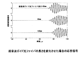
図2には、図1に示す装置において被検体5として大きさ300mm×300mm、厚さ1mmのアルミ板を用い、超音波ガイド光ファイバ2の長さを80、90、105mmとした場合の実験から得られた超音波応答結果を示す。このとき超音波ガイドとしてポリイミドコーティングを施した外径135μmの1550nm帯シングルモード光ファイバを用い、カップラント3としてひずみゲージ用接着剤を用いた。
FIG. 2 shows an experiment in the case where an aluminum plate having a size of 300 mm × 300 mm and a thickness of 1 mm is used as the subject 5 in the apparatus shown in FIG. 1 and the length of the ultrasonic guide
370kHzの5周期トーン・バースト信号を超音波励起信号とし、圧電超音波センサ7は超音波ガイド光ファイバ2軸上に取り付けた。超音波ガイド光ファイバ2が長くなるに従い、応答開始時間が遅れていることが観察され、光ファイバ2による超音波ガイドが機能していることが確認できる。
A 370 kHz 5-period tone burst signal was used as the ultrasonic excitation signal, and the piezoelectric ultrasonic sensor 7 was mounted on the two axes of the ultrasonic guide optical fiber. As the ultrasonic guide
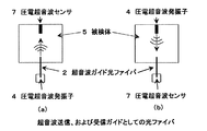
図3(a)は、図1に示した超音波送受信装置の要部を説明する図である。この図において、圧電超音波発振子4から発生した超音波は光ファイバ2を通して被検体5に伝わり、それを圧電超音波センサ7により検出することになる。
FIG. 3A is a diagram for explaining a main part of the ultrasonic transmission / reception apparatus shown in FIG. In this figure, the ultrasonic wave generated from the piezoelectric ultrasonic oscillator 4 is transmitted to the subject 5 through the
圧電超音波センサ7の圧電素子は超音波発振とセンサの二つの機能を併せ持つことから、この装置は図3(b)に示すように二つの圧電素子の超音波発振子とセンサの役割を逆にすることができる。つまり被検体5に取り付けた圧電超音波発振子4から超音波を発振させ、被検体5に取り付けた光ファイバ2を通して圧電超音波センサ7で超音波を受信することができる。つまり図3(a)、および図3(b)の二つの構成において光ファイバ2はそれぞれ超音波送信ガイド、および受信ガイドとしての機能を果たす。
Since the piezoelectric element of the piezoelectric ultrasonic sensor 7 has both the functions of ultrasonic oscillation and sensor, this apparatus reverses the roles of the ultrasonic oscillator and sensor of the two piezoelectric elements as shown in FIG. Can be. That is, an ultrasonic wave can be oscillated from the piezoelectric ultrasonic oscillator 4 attached to the subject 5 and the ultrasonic wave can be received by the piezoelectric ultrasonic sensor 7 through the
図4に図3に示した二つの構成から検出された超音波応答信号を示す。この図から超音波ガイド光ファイバ2は超音波送信、受信ガイドとしての両方の機能を持つことが確認できる。つまり図1に示した信号発生側と信号収録側の装置を逆に配置することにより、光ファイバ2を超音波送信、および受信ガイドの機能に切り替えることができる。
FIG. 4 shows ultrasonic response signals detected from the two configurations shown in FIG. From this figure, it can be confirmed that the ultrasonic guide
以上、超音波ガイド光ファイバ2を介して伝達された超音波を圧電超音波センサ7により検出した例を示した。光ファイバ2を伝搬する超音波は光ファイバ2にFBG10を設け、特開2005−009937号公報(広帯域光源と光学フィルタを組み合わせた装置)、または特願2005−326326号公報(波長可変レーザ光源を用いた装置)に記載したFBG超音波検出装置を用いて検出できることができる。
The example in which the ultrasonic wave transmitted through the ultrasonic guide
FBG10はブラッグ波長を中心に狭帯域の光を反射する性質を持つ。この反射帯域はFBG10のグレーティング長さに依存するが、グレーティング長さ1mm、および10mmのとき、それぞれ約2nm、および0.2nmの反射帯域を有する。FBG10のブラッグ波長はFBG10が受ける温度、およびひずみに応じて変化することが知られている。超音波やAEはkHzオーダを超える高速で微小なひずみ変化を与えることから、超音波ガイド光ファイバ2を伝搬する超音波やAEがFBG10を通過した際、FBG10のブラッグ波長はそれに応じて変動する。
The
波長可変レーザ光源11を用いた場合、ブラッグ波長を中心とした狭帯域光の反射分布の中で反射率が半減する波長のレーザをFBG10に入射する。超音波及びAEがもたらすひずみによりレーザ発振波長における反射率が変動することから、FBG10からの反射光強度はFBG10を通過する超音波及びAEに応じて変化することになる。
When the wavelength tunable
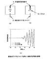
図5(a)は、本発明の実施例2の材料健全性評価装置12を説明する図である。この装置では、光源として狭帯域光を放射するレーザを利用している。この装置は、被検体5として用いた大きさ300×300mm、厚さ1mmのアルミ板に図に示すように圧電超音波発振子4と超音波ガイド光ファイバ2を取り付けFBG超音波検出装置の構成とした。超音波ガイド光ファイバ2にはFBG10が書き込まれており、その他端は光サーキュレータ13に接続されている。
Fig.5 (a) is a figure explaining the material
FBG10の反射率が半減する波長に設定されたレーザ光は光サーキュレータ13を介してFBG10に入射される。FBG10からの反射光は光サーキュレータ13を通して光電変換器14に入射され、光強度は電圧信号に変換され信号収録装置15に記録される。
Laser light set to a wavelength at which the reflectance of the
図5(b)に、図5(a)の装置(超音波ガイド光ファイバ2の被検体5とFBG10との距離は120mm)から検出された超音波応答信号を示す。このようにFBG超音波検出装置と超音波ガイド光ファイバ2を組み合わせた装置を用いて超音波を検出することができる。
FIG. 5B shows an ultrasonic response signal detected from the apparatus shown in FIG. 5A (the distance between the subject 5 of the ultrasonic guide
ここでは、レーザを光源とした場合を挙げたが、広帯域光源とFBG反射光をフィルタ処理する装置(特開2005−009937号参照)との組合せにおいても同様に超音波検出ができる。 Here, a case where a laser is used as a light source has been described, but ultrasonic detection can be similarly performed in a combination of a broadband light source and an apparatus for filtering FBG reflected light (see Japanese Patent Application Laid-Open No. 2005-009937).
被検体5に直接FBG10を取り付けた場合、その反射率が低下しFBG10のセンサとしての機能が消失するような高温であっても、図5(a)のように超音波ガイド光ファイバ2を利用したときFBG10は高温にならないため、被検体5を伝搬する超音波及びAEを検出することができる。また被検体5が受ける温度・ひずみがFBG10のブラッグ波長変動に及ぼす影響を抑えることができ、超音波検出感度を最大に保持した状態で超音波及びAE検出することが可能になる。
When the
図6は、本発明の実施例3の材料健全性評価装置を説明する図である。図5(a)ではFBG10の位置が超音波ガイド光ファイバ2の被検体5への取り付け部と光サーキュレータ13の間にあるが、図6のように、この実施例3では、被検体5の取り付け位置から超音波ガイド光ファイバ2の終端部の間にFBG10を設けても同様に超音波及びAE検出機能を有する。またこのように被検体5が置かれた雰囲気と同じ場所にFBG10を設けることにより、温度センサとしての機能を追加することができる。つまりFBG10のブラッグ波長は被検体5に伝搬する超音波及びAE、および温度に応じて変化することになる。
FIG. 6 is a diagram for explaining the material soundness evaluation apparatus according to the third embodiment of the present invention. In FIG. 5A, the position of the
超音波及びAEによるブラッグ波長変化は1pm以下と非常に微小なため、その検出には超音波検出装置が必要になるが、温度によるブラッグ波長変化はブラッグ波長が1550nmの場合、1℃あたり約10pmと大きいことから波長計などのブラッグ波長を測定する計測器を用いて被検体5の置かれた雰囲気の温度を計測することができる。 Since the Bragg wavelength change due to the ultrasonic wave and AE is very small as 1 pm or less, an ultrasonic detector is required for the detection. However, the Bragg wavelength change due to temperature is about 10 pm per 1 ° C. when the Bragg wavelength is 1550 nm. Therefore, the temperature of the atmosphere in which the subject 5 is placed can be measured using a measuring instrument that measures the Bragg wavelength, such as a wavelength meter.
また、図7のように中空容器の中にFBG10を書き込んだ光ファイバ17を接着剤、接着テープやグリースなどのカップラント3を用いて封入することにより、FBG10を保護した超音波及びAE、および温度センサになる。このような構成にした場合、中空容器16内部の光ファイバが超音波ガイド光ファイバ2として機能する。したがって、中空容器16以外の光ファイバ17は超音波送受信に利用されないことから、破断などを保護するための丈夫なジャケットをつけることができ、取り扱いを非常に便利にすることができる。
Further, as shown in FIG. 7, the optical fiber 17 in which the
図8は、実施例5を説明する図である。この実施例5は、光ファイバ2の超音波ガイド機能におけるファイバ軸方向に強い超音波受信指向性を考慮した構成である。図8(a)に示すように圧電超音波発振子4を厚さ1mmのアルミ板上に取り付け、圧電超音波発振子4から150mm離れた箇所に超音波ガイド光ファイバ2を取り付けた。このとき矩形状圧電超音波発振子4長手方向と一致する超音波伝搬方向に対して0°、45°、90°方向の三方向に光ファイバ2をアルミ板に取り付けた。
FIG. 8 is a diagram for explaining the fifth embodiment. The fifth embodiment is configured in consideration of the strong directivity of ultrasonic reception in the fiber axis direction in the ultrasonic guide function of the
超音波ガイド光ファイバ2の他端には圧電超音波センサ7を貼り付けて、超音波受信感度の指向性を調べた。図中、接着剤を用いて被検体5に貼り付けた超音波ガイド光ファイバ2の箇所を実線で、被検体5に貼り付けていない部分を点線で表した。
A piezoelectric ultrasonic sensor 7 was attached to the other end of the ultrasonic guide
図8図(b)にそれぞれの方向の超音波ガイド光ファイバ2から検出された超音波応答信号を示す。このように超音波伝搬方向と光ファイバ2の軸方向が一致した0°方向の光ファイバ2から検出された応答強度がもっとも高く、続いて45°方向の感度が高く、超音波伝搬方向と垂直に貼り付けた90°方向の光ファイバ2から検出された超音波応答強度は最も低い。
FIG. 8B shows an ultrasonic response signal detected from the ultrasonic guide
また0°、45°、90°方向の光ファイバ2と接触させた圧電超音波センサ7の応答信号を加算して得られる信号は超音波検出の指向性を広げた応答信号に対応する。
A signal obtained by adding the response signals of the piezoelectric ultrasonic sensor 7 brought into contact with the
図9(a)は、実施例6を説明する図である。この実施例6は、この図9(a)に示すように、図8(a)における0°、45°、90°方向の光ファイバ2の端部をカップラント3を用いて接触させ、一つの圧電超音波センサ7に取り付ける。この圧電超音波センサ7から検出された応答信号を図8(b)の一番上に示す。
FIG. 9A is a diagram for explaining the sixth embodiment. In Example 6, as shown in FIG. 9A, the ends of the
このときカップラント3としてはひずみゲージ用接着剤を用いた。このように異なる方向に取り付けた複数の超音波ガイド光ファイバ2を伝搬してきた超音波をまとめて一つの圧電センサで検出することにより広い指向性を有する超音波ガイド光ファイバ2としての機能を持たせることができる。
At this time, a strain gauge adhesive was used as the coupling 3. In this way, the ultrasonic wave propagating through a plurality of ultrasonic guide
これは、超音波検出の指向性を広げる手段としては、前記0°、45°、90°方向の光ファイバ2と接触させた圧電超音波センサ7の応答信号を加算して得られる信号は超音波検出の指向性を広げた応答信号に対応する例よりも圧電超音波素子の数を少なくすることができる。
As a means for expanding the directivity of ultrasonic detection, the signal obtained by adding the response signals of the piezoelectric ultrasonic sensor 7 brought into contact with the
この場合、超音波検出センサ7としてFBG10を用いる場合、図9(b)のようにそれぞれの超音波ガイド光ファイバ2の一部をカップラント3で接触させることにより、それぞれの超音波ガイド光ファイバ2に伝搬する超音波を合成することができる。
In this case, when the
そして、一本の超音波ガイド光ファイバ2に設けたFBG10を用いて合成された超音波を検出することができる。またそれぞれの超音波ガイド光ファイバ2にFBG10を書き込み、それぞれのFBG10センサから得られる応答を加算しても同様な機能を得ることができる。
Then, it is possible to detect an ultrasonic wave synthesized using the
以上の例では超音波検出のみを取り上げているが、材料の欠陥発生時に生じるAEも同様にして検出することができる。 In the above example, only ultrasonic detection is taken up, but AE generated when a defect in the material occurs can be detected in the same manner.
図10は、実施例7を説明する図である。この実施例7は、超音波ガイド光ファイバを、被検体5よりも超音波音速の低い材質の超音波ガイド光ファイバ取り付具18に取り付けるようにしたものである。被検体5を伝搬する超音波及びAEは音速の低い物質に流入することから、超音波ガイド光ファイバ2に到達する。超音波ガイド光ファイバ2をループ状に取付け具に取り付けた場合、全方位から伝搬してくる超音波及びAEを超音波ガイド光ファイバ2が受信することが出来ると考えられる。
FIG. 10 is a diagram for explaining the seventh embodiment. In the seventh embodiment, the ultrasonic guide optical fiber is attached to the ultrasonic guide optical fiber attachment 18 made of a material having an ultrasonic sound velocity lower than that of the subject 5. Since the ultrasonic waves and AE propagating through the subject 5 flow into a substance having a low sound velocity, they reach the ultrasonic guide
もし超音波ガイド光ファイバ取付け具18を用いずに直接、超音波ガイド光ファイバ2を被検体5にループ状に貼り付けた場合は、被検体5に接触している箇所から超音波及びAEは光ファイバ2に流入してくるが、同時に流出することが考えられる。このため全方位指向性を有さない超音波及びAE検出超音波ガイド光ファイバになると考えられる。
If the ultrasonic guide
(実験例)
本発明の材料健全性評価装置の健全性評価に関する実験例を図11に示す。この実験例では、大きさ300×300mm、厚さ1mmのアルミ板に圧電超音波発振子4と超音波ガイド光ファイバ2を取り付け、圧電超音波発振子4と超音波ガイド光ファイバ2を結ぶ直線上に欠陥がない場合(図11(a))、長さ18mm、幅2mmのスリット19による欠陥(スリット欠陥)を導入した場合(図11(b))の超音波ガイド光ファイバ2の他端に取り付けた圧電超音波センサ(図示せず。)から検出された超音波を比較した。
(Experimental example)
An experimental example relating to the soundness evaluation of the material soundness evaluation apparatus of the present invention is shown in FIG. In this experimental example, the piezoelectric ultrasonic oscillator 4 and the ultrasonic guide
図11(c)に示すようにスリット19がない場合と比較して、スリット19を導入後の応答は超音波がスリット19を迂回することによる応答時間遅れと超音波応答減衰が観察される。このように超音波ガイド光ファイバ2を用いて超音波を利用した構造体の欠陥検出を行うことができる。
As shown in FIG. 11C, compared to the case without the slit 19, the response after introducing the slit 19 is observed as a response time delay and an ultrasonic response attenuation due to the ultrasonic wave bypassing the slit 19. In this way, it is possible to detect defects in the structure using ultrasonic waves using the ultrasonic guide
図12は、実施例8を説明する図である。この実施例8の材料健全性評価装置は、超音波ガイド光ファイバ2を用いた欠陥発生箇所20の位置標定可能とするものである。被検体5の複数個所に超音波ガイド光ファイバ2を取り付け、被検体5に発生するAEを光ファイバ2で受信できるようにする。超音波ガイド光ファイバ2のもう一方の端部に超音波センサに取り付ける。
FIG. 12 is a diagram for explaining the eighth embodiment. The material soundness evaluation apparatus of Example 8 is capable of locating the
センサの応答波形を収録し、応答波形の到達時間差を調べることにより、AE発生源となった欠陥発生箇所20の位置標定を行うことができる。なお、この実施例8では、図11(a)に示す圧電超音波センサ7を用いてAE検出を行っているが、FBG超音波検出装置を用いても同様の機能を果たすことができる。
By recording the response waveform of the sensor and examining the arrival time difference between the response waveforms, it is possible to determine the position of the
図13は、実施例9を説明する図である。この実施例9の材料健全性評価装置は、被検体5には超音波ガイド光ファイバ2のみを取り付け、光ファイバ2のみにより超音波送受信を行い健全性評価装置とすることもできるものである。この場合、被検体5の温度・形状・材質に関わらず超音波送受信を行うことができる。
FIG. 13 is a diagram for explaining the ninth embodiment. In the material soundness evaluation apparatus of Example 9, only the ultrasonic guide
図13で示す実施例9では、超音波送受信ガイドは一対のみであるが、複数対の超音波ガイド光ファイバ2を超音波送受信ガイドとして設けることにより広域な範囲を検査する健全性評価装置を構築することができる。また図13中、圧電超音波センサ7を用いて超音波検出を行っているが、FBG超音波検出装置を用いても同様の機能を果たすことができる。
In the ninth embodiment shown in FIG. 13, only one pair of ultrasonic transmission / reception guides is provided, but a soundness evaluation apparatus for inspecting a wide range is constructed by providing a plurality of pairs of ultrasonic guide
図14は、実施例10を説明する図である。この実施例10は、レーザを超音波励起源に用いた超音波発振方式と超音波ガイド光ファイバ2の組合せによる健全性評価装置の例を示す。超音波励起レーザ光源21からレーザを発振させることにより被検体5に超音波を発生させ、被検体5を伝搬する超音波を超音波ガイド光ファイバ2により受信し、後段に設けた圧電超音波センサ7で検出する。このとき被検体5が磁性材料であるならばEMATを用いて超音波励起してもよい。
FIG. 14 is a diagram for explaining the tenth embodiment. The tenth embodiment shows an example of a soundness evaluation apparatus using a combination of an ultrasonic oscillation method using a laser as an ultrasonic excitation source and an ultrasonic guide
この実施例10の材料健全性評価装置では、レーザ、およびEMATによる超音波励起は、超音波ガイド光ファイバ2による超音波送信よりもより強力な超音波を発生することができる利点がある。また図14中、圧電超音波センサ7を用いて超音波検出を行っているが、FBG超音波検出装置を用いても同様の機能を果たすことができる。
In the material soundness evaluation apparatus according to the tenth embodiment, ultrasonic excitation by laser and EMAT is advantageous in that it can generate stronger ultrasonic waves than ultrasonic transmission by the ultrasonic guide
以上、本発明に係る材料健全性評価装置の最良の形態を実施例に基づいて説明したが、本発明はこのような実施例に限定されることなく、特許請求の範囲記載の技術的事項の範囲内で、いろいろな実施例があることは言うまでもない。 As mentioned above, although the best form of the material soundness evaluation apparatus based on this invention was demonstrated based on the Example, this invention is not limited to such an Example, The technical matter of a claim is described. It goes without saying that there are various embodiments within the scope.
本発明は、以上のような構成であるから、建築構造物、橋梁や道路などのインフラストラクチャー、輸送機、エネルギープラントなど、その信頼性確保のためにその健全性が定期的に、または常時監視するべき構造物の非破壊検査手段としての利用が最適である。 Since the present invention is configured as described above, the soundness of building structures, infrastructures such as bridges and roads, transportation equipment, energy plants, etc. is regularly or constantly monitored to ensure their reliability. It is optimal to use it as a non-destructive inspection tool for the structure to be done.
1 超音波送受信装置
2 超音波ガイド光ファイバ
3 カップラント
4 圧電超音波発振子
5 被検体
6 信号発生器
7 圧電超音波センサ
8 信号収録装置
9 信号増幅器
10 FBG
11 波長可変レーザ光源
12 材料健全性評価装置
13 光サーキュレータ
14 光電変換器
15 信号収録装置
16 中空容器
17 光ファイバ
18 超音波ガイド光ファイバ取り付具
19 スリット
20 欠陥発生箇所
21 超音波励起レーザ光源
DESCRIPTION OF
DESCRIPTION OF
Claims (11)
前記圧電超音波発振子は、発生した超音波を前記超音波ガイド光ファイバに伝達させ、
前記超音波ガイド光ファイバは、前記圧電超音波発振子に一端が取り付けられ、かつ一部が健全性評価対象となる被検体の内部または表面に取り付けられ、前記超音波を前記被検体に伝達するものであり、
前記測定手段は、前記超音波の伝搬状況により被検体中の欠陥の存在の有無を検査することを特徴とする材料健全性評価装置。 A piezoelectric ultrasonic oscillator, a material integrity evaluation device comprising an ultrasonic guide optical fiber, and a measuring means for measuring the propagation state of the ultrasonic wave transmitted to the subject,
The piezoelectric ultrasonic oscillator causes the transmitted ultrasonic waves generated before Symbol ultrasound guided optical fiber,
The ultrasound-guided optical fiber, said piezoelectric one end to the ultrasonic vibrator is attached, and attached to the interior or surface of the subject part is soundness evaluation, to transmit the ultrasonic wave to the subject Is,
Said measuring means, said ultrasonic material integrity evaluation apparatus according to claim inspection to Rukoto the presence or absence of defects in the specimen by the propagation conditions of the.
前記超音波ガイド光ファイバは、一部が健全性評価対象となる被検体の内部または表面に取り付けられ、該被検体からの超音波またはAEを受信する機能を有し、前記被検体を伝搬する超音波またはAEを前記測定手段に伝搬するものであり、
前記測定手段は、前記被検体の超音波またはAEの伝搬状況により被検体中の欠陥の存在の有無を検査することを特徴とする材料健全性評価装置。 A material soundness evaluation apparatus comprising an ultrasonic guide optical fiber and a measuring means for measuring a propagation state of ultrasonic waves transmitted to a subject ,
A part of the ultrasonic guide optical fiber is attached to the inside or the surface of a subject to be evaluated for soundness, has a function of receiving ultrasonic waves or AE from the subject, and propagates through the subject. Propagating ultrasound or AE to the measuring means,
Said measurement means, the subject of the ultrasound or AE whether the inspection to Rukoto wood charge integrity evaluation device you wherein the presence of defects in a specimen by the propagation conditions of the.
前記圧電超音波センサ又は前記FBGは、複数本の超音波ガイド光ファイバにそれぞれ設けられている構成、若しくは複数本の超音波ガイド光ファイバの他端がカップラントにより一つにまとめられて設けられている構成であることを特徴とする請求項3〜6のいずれか1項に記載の材料健全性評価装置。 A plurality of the ultrasonic guide optical fibers are provided, and the plurality of ultrasonic guide optical fibers are attached to the subject in a plurality of different directions to the subject, thereby expanding the directivity of detection of ultrasonic waves or AEs. It is made up of
The piezoelectric ultrasonic sensor or the FBG is provided in each of a plurality of ultrasonic guide optical fibers, or the other ends of the plurality of ultrasonic guide optical fibers are provided together by a coupling. and that the material integrity evaluation device according to any one of claims 3-6, characterized in that the configuration.
前記圧電超音波発振子は、発生した超音波を前記超音波ガイド光ファイバに伝達させ、
前記第1の超音波ガイド光ファイバは、前記圧電超音波発振子に一端が取り付けられ、かつ一部が健全性評価対象となる被検体の内部または表面に取り付けられ、前記超音波を前記被検体に伝達するものであり、
前記第2の超音波ガイド光ファイバは、一部が健全性評価対象となる被検体の内部または表面に取り付けられ、該被検体からの超音波を受信する機能を有し、前記被検体を伝搬する超音波を前記測定手段に伝搬するものであり、
前記測定手段は、前記被検体の超音波の伝搬状況により被検体中の欠陥の存在の有無を検査することを特徴とする材料健全性評価装置。 A material soundness evaluation apparatus comprising: a piezoelectric ultrasonic oscillator; first and second ultrasonic guide optical fibers; and a measuring unit that measures a propagation state of ultrasonic waves transmitted to a subject .
The piezoelectric ultrasonic oscillator transmits the generated ultrasonic waves to the ultrasonic guide optical fiber ,
One end of the first ultrasonic guide optical fiber is attached to the piezoelectric ultrasonic oscillator, and a part of the first ultrasonic guide optical fiber is attached to the inside or the surface of a subject to be evaluated for soundness. To communicate to
A part of the second ultrasonic guide optical fiber is attached to the inside or the surface of a subject to be evaluated for soundness, and has a function of receiving ultrasonic waves from the subject, and propagates through the subject. Propagating ultrasonic waves to the measuring means ,
The material soundness evaluation apparatus characterized in that the measuring means inspects the presence or absence of a defect in the subject based on an ultrasonic wave propagation state of the subject .
Priority Applications (1)
| Application Number | Priority Date | Filing Date | Title |
|---|---|---|---|
| JP2006066290A JP4635186B2 (en) | 2006-03-10 | 2006-03-10 | Material integrity evaluation system |
Applications Claiming Priority (1)
| Application Number | Priority Date | Filing Date | Title |
|---|---|---|---|
| JP2006066290A JP4635186B2 (en) | 2006-03-10 | 2006-03-10 | Material integrity evaluation system |
Publications (2)
| Publication Number | Publication Date |
|---|---|
| JP2007240447A JP2007240447A (en) | 2007-09-20 |
| JP4635186B2 true JP4635186B2 (en) | 2011-02-16 |
Family
ID=38586120
Family Applications (1)
| Application Number | Title | Priority Date | Filing Date |
|---|---|---|---|
| JP2006066290A Expired - Fee Related JP4635186B2 (en) | 2006-03-10 | 2006-03-10 | Material integrity evaluation system |
Country Status (1)
| Country | Link |
|---|---|
| JP (1) | JP4635186B2 (en) |
Families Citing this family (12)
| Publication number | Priority date | Publication date | Assignee | Title |
|---|---|---|---|---|
| JP5624271B2 (en) * | 2008-09-17 | 2014-11-12 | 株式会社東芝 | Piping thickness measurement method and apparatus |
| KR100923104B1 (en) | 2008-09-19 | 2009-10-27 | 전남대학교산학협력단 | Optical Fiber Gas Sensor Using Ultrasonic Wave |
| KR100923106B1 (en) | 2008-09-19 | 2009-10-22 | 전남대학교산학협력단 | Ultrasonic Fiber Optic Sensor |
| WO2010032979A2 (en) * | 2008-09-19 | 2010-03-25 | 전남대학교산학협력단 | Optical fiber sensor and optical fiber gas sensor which use ultrasonic waves |
| KR101062951B1 (en) | 2008-12-30 | 2011-09-06 | 주식회사 포스코 | Fatigue Test Method |
| JP5586009B2 (en) * | 2010-01-22 | 2014-09-10 | 独立行政法人産業技術総合研究所 | Vibration detection system, apparatus using the system, and vibration detection method |
| JP5586011B2 (en) | 2010-03-18 | 2014-09-10 | 独立行政法人産業技術総合研究所 | FBG vibration detection system, apparatus using the system, and vibration detection method |
| JP6246751B2 (en) | 2015-02-12 | 2017-12-13 | 株式会社日立製作所 | Insulation deterioration detection system, insulation deterioration detection method, and insulation deterioration detection sensor |
| JP6329188B2 (en) * | 2016-02-29 | 2018-05-23 | 株式会社Subaru | Ultrasonic inspection system, ultrasonic inspection method and aircraft structure |
| CN108195943B (en) * | 2018-03-12 | 2023-11-03 | 中国工程物理研究院化工材料研究所 | Optical fiber acoustic emission system for monitoring explosive damage and destruction process and monitoring method thereof |
| JP7429410B2 (en) * | 2019-10-30 | 2024-02-08 | 一般財団法人生産技術研究奨励会 | Optical fiber sensing system, damage monitoring method, and damage location imaging method |
| CN115900925B (en) * | 2022-10-25 | 2025-09-19 | 南京航空航天大学 | Piezoelectric-optical fiber composite ultrasonic sensor and detection method thereof |
Family Cites Families (3)
| Publication number | Priority date | Publication date | Assignee | Title |
|---|---|---|---|---|
| JP2003275206A (en) * | 2002-03-22 | 2003-09-30 | Seiko Instruments Inc | Ultrasonic examination apparatus having position detection function |
| JP4342325B2 (en) * | 2004-01-21 | 2009-10-14 | 株式会社Ihiエアロスペース | Ultrasonic wall thickness measuring device |
| JP2005326326A (en) * | 2004-05-17 | 2005-11-24 | National Institute Of Advanced Industrial & Technology | Strain measurement using optical fiber sensor and ultrasonic / AE detector |
-
2006
- 2006-03-10 JP JP2006066290A patent/JP4635186B2/en not_active Expired - Fee Related
Also Published As
| Publication number | Publication date |
|---|---|
| JP2007240447A (en) | 2007-09-20 |
Similar Documents
| Publication | Publication Date | Title |
|---|---|---|
| JP5586011B2 (en) | FBG vibration detection system, apparatus using the system, and vibration detection method | |
| JP3517699B2 (en) | Vibration measuring apparatus and vibration measuring method | |
| US9158054B2 (en) | Acousto-ultrasonic sensor | |
| JP4635186B2 (en) | Material integrity evaluation system | |
| JP5624271B2 (en) | Piping thickness measurement method and apparatus | |
| US12265060B2 (en) | Device and method for testing a test object | |
| JP5586009B2 (en) | Vibration detection system, apparatus using the system, and vibration detection method | |
| US10900934B2 (en) | Acoustic black hole for sensing applications | |
| CA1268535A (en) | Laser induced acoustic generation for sonic modulus | |
| Dass et al. | In reflection metal-coated diaphragm microphone using PCF modal interferometer | |
| Lee et al. | Investigation of a fibre wave piezoelectric transducer | |
| Luo et al. | Multi-point fiber optic laser-ultrasonic transducer based on long-period fiber grating | |
| Liu et al. | Detection of fundamental shear horizontal guided waves using a surface-bonded chirped fiber-Bragg-grating Fabry–Perot interferometer | |
| JP4469939B2 (en) | Optical fiber sensor leak detector | |
| Naeem et al. | Pipeline damage detection using multimode fiber optic acoustic sensor and ultrasonic guided waves | |
| Li et al. | Doppler effect-based fiber-optic sensor and its application in ultrasonic detection | |
| JP4565093B2 (en) | Movable FBG ultrasonic sensor | |
| JP2012122751A (en) | Material deterioration diagnostic device | |
| Naeem et al. | No-core fiber based multipoint ultrasonic acoustic sensors for energy infrastructure monitoring | |
| Lee et al. | Integrated guided wave generation and sensing using a single laser source and optical fibers | |
| Quesson et al. | Feasibility of an all-optical scalable network architecture for non-destructive testing of composite plates | |
| JP6153240B2 (en) | Non-contact acoustic inspection equipment | |
| Zhou et al. | Guided wave-based pipe damage inspection by ultrasonic fiber optic sensor | |
| Han et al. | Damage monitoring of aluminum alloy structure based on remote bonding fiber Bragg gratings sensing | |
| Wang et al. | Amplification of Ultrasonic-to-Fiber Bragg Grating Signals |
Legal Events
| Date | Code | Title | Description |
|---|---|---|---|
| A621 | Written request for application examination |
Free format text: JAPANESE INTERMEDIATE CODE: A621 Effective date: 20080327 |
|
| A131 | Notification of reasons for refusal |
Free format text: JAPANESE INTERMEDIATE CODE: A131 Effective date: 20100803 |
|
| A521 | Request for written amendment filed |
Free format text: JAPANESE INTERMEDIATE CODE: A523 Effective date: 20101001 |
|
| TRDD | Decision of grant or rejection written | ||
| A01 | Written decision to grant a patent or to grant a registration (utility model) |
Free format text: JAPANESE INTERMEDIATE CODE: A01 Effective date: 20101026 |
|
| A01 | Written decision to grant a patent or to grant a registration (utility model) |
Free format text: JAPANESE INTERMEDIATE CODE: A01 |
|
| A61 | First payment of annual fees (during grant procedure) |
Free format text: JAPANESE INTERMEDIATE CODE: A61 Effective date: 20101027 |
|
| FPAY | Renewal fee payment (event date is renewal date of database) |
Free format text: PAYMENT UNTIL: 20131203 Year of fee payment: 3 |
|
| R150 | Certificate of patent or registration of utility model |
Free format text: JAPANESE INTERMEDIATE CODE: R150 |
|
| FPAY | Renewal fee payment (event date is renewal date of database) |
Free format text: PAYMENT UNTIL: 20131203 Year of fee payment: 3 |
|
| R250 | Receipt of annual fees |
Free format text: JAPANESE INTERMEDIATE CODE: R250 |
|
| S533 | Written request for registration of change of name |
Free format text: JAPANESE INTERMEDIATE CODE: R313533 |
|
| R350 | Written notification of registration of transfer |
Free format text: JAPANESE INTERMEDIATE CODE: R350 |
|
| R250 | Receipt of annual fees |
Free format text: JAPANESE INTERMEDIATE CODE: R250 |
|
| LAPS | Cancellation because of no payment of annual fees |