JP4634097B2 - Optical film laminate and liquid crystal display device including the same - Google Patents
Optical film laminate and liquid crystal display device including the same Download PDFInfo
- Publication number
- JP4634097B2 JP4634097B2 JP2004249740A JP2004249740A JP4634097B2 JP 4634097 B2 JP4634097 B2 JP 4634097B2 JP 2004249740 A JP2004249740 A JP 2004249740A JP 2004249740 A JP2004249740 A JP 2004249740A JP 4634097 B2 JP4634097 B2 JP 4634097B2
- Authority
- JP
- Japan
- Prior art keywords
- film
- layer
- polarizing film
- liquid crystal
- optical film
- Prior art date
- Legal status (The legal status is an assumption and is not a legal conclusion. Google has not performed a legal analysis and makes no representation as to the accuracy of the status listed.)
- Active
Links
Images


Description
本発明は液晶ディスプレイなどの各種画像表示装置に使用する光学フィルム積層体に関し、詳しくは反射性偏光フィルムと吸収性偏光フィルムとを積層した光学フィルム積層体に関する。さらにこれを用いた液晶表示装置に関する。 The present invention relates to an optical film laminate used for various image display devices such as a liquid crystal display, and more particularly to an optical film laminate in which a reflective polarizing film and an absorbent polarizing film are laminated. Further, the present invention relates to a liquid crystal display device using the same.
従来から、吸収性偏光フィルムは液晶表示装置に多く使用されており、その需要は急激に増加している。さらに、近年では、光学補償機能を付加した吸収性偏光フィルムのように、付加価値の高いものが使用されてきており、例えば、色相、輝度、コントラスト、広視野角等の点で表示品位に対する要求がより一層強く要求される傾向にある。 Conventionally, absorptive polarizing films have been widely used in liquid crystal display devices, and the demand thereof has been increasing rapidly. Furthermore, in recent years, high-value-added films have been used, such as an absorptive polarizing film with an optical compensation function. For example, there is a demand for display quality in terms of hue, brightness, contrast, wide viewing angle, and the like. There is a tendency to be more strongly demanded.
表示品位の中でも特に輝度向上を目的として、反射性偏光フィルムが吸収性偏光フィルムと共に使用されている。反射性偏光フィルムは、通常、液晶表示装置におけるバックライトユニットと偏光フィルムとの間に配置され、本来なら偏光フィルムに吸収されてしまう光を反射して再利用することによって、表示画面の輝度を向上させるものである。このような輝度向上フィルムとしては、例えば、複屈折を有するポリマーの多層積層フィルム、コレステリック液晶フィルム等が知られており、一般に、前記ポリマーフィルムの積層体は直線偏光を反射し、前記コレステリック液晶フィルムは円偏光を反射する。前記コレステリック液晶フィルムは、円偏光を反射するため、1/4波長板を組み合わせて直線偏光を反射させる。 Among display quality, a reflective polarizing film is used together with an absorptive polarizing film for the purpose of improving luminance. A reflective polarizing film is usually disposed between a backlight unit and a polarizing film in a liquid crystal display device, and reflects and reuses light that would otherwise be absorbed by the polarizing film, thereby improving the brightness of the display screen. It is to improve. As such a brightness enhancement film, for example, a multilayer laminated film of a polymer having birefringence, a cholesteric liquid crystal film, and the like are known. Generally, the laminate of the polymer film reflects linearly polarized light, and the cholesteric liquid crystal film Reflects circularly polarized light. Since the cholesteric liquid crystal film reflects circularly polarized light, it reflects linearly polarized light by combining a quarter wave plate.
例えば、バックライトからの光を、反射偏光フィルムにおいて、P偏光、S偏光とを分離して、いずれか一方の直線偏光を透過させ、透過した直線偏光を吸収性偏光フィルムに供給する。一方、反射偏光フィルムにおいて反射された光は、例えば、前記バックライトの裏側に配置された反射板によって偏光状態が変化され、再度、反射偏光フィルムに戻り、ここでさらに分離されるのである。 For example, the light from the backlight is separated into P-polarized light and S-polarized light in the reflective polarizing film, one of the linearly polarized light is transmitted, and the transmitted linearly polarized light is supplied to the absorptive polarizing film. On the other hand, the light reflected by the reflective polarizing film is changed in its polarization state by, for example, a reflective plate disposed on the back side of the backlight, and returns to the reflective polarizing film, where it is further separated.
一般に多層積層フィルムは、屈折率の低い層と高い層とを交互に多数積層したものであり、層間の構造的な光干渉によって、特定波長の光を選択的に反射または透過する光学干渉フィルムとすることができる。また、このような多層積層フィルムは、膜厚を徐々に変化させたり、異なる反射ピークを有するフィルムを貼り合せたりすることで金属を使用したフィルムと同等の高い反射率を得ることができ、金属光沢フィルムや反射ミラーとして使用することもできる。さらには、このような多層積層フィルムを1方向にのみ延伸することで、特定の偏光成分のみを反射する偏光反射フィルムとしても使用できる。 In general, a multilayer laminated film is obtained by alternately laminating a plurality of layers having a low refractive index and a layer having a high refractive index, and an optical interference film that selectively reflects or transmits light of a specific wavelength by structural optical interference between the layers. can do. In addition, such a multilayer laminated film can obtain a high reflectivity equivalent to a film using metal by gradually changing the film thickness or by laminating films having different reflection peaks. It can also be used as a glossy film or a reflection mirror. Furthermore, it can be used as a polarizing reflection film that reflects only a specific polarization component by stretching such a multilayer laminated film only in one direction.
一般に層厚が0.05〜0.5μmの異なる屈折率を持った層で構成される多層光学フィルムは、一方の層を構成する層と他方の層を構成する層の屈折率差と膜厚および積層数により特定の波長の光を反射する増反射といった現象がみられる。一般にその反射波長は、下記の式で示される。
λ=2x((n1)x(d1)+(n2)x(d2))
ここで、λは反射波長(nm)、n1、n2はそれぞれの層の屈折率、d1、d2は、それぞれの層の厚み(nm)である。
In general, a multilayer optical film composed of layers having different refractive indexes of 0.05 to 0.5 μm is different in refractive index and film thickness between a layer constituting one layer and a layer constituting the other layer. In addition, there is a phenomenon such as increased reflection in which light having a specific wavelength is reflected depending on the number of stacked layers. In general, the reflection wavelength is expressed by the following equation.
λ = 2x ((n1) x (d1) + (n2) x (d2))
Here, λ is the reflection wavelength (nm), n1 and n2 are the refractive indexes of the respective layers, and d1 and d2 are the thicknesses (nm) of the respective layers.
特開平04−268505号公報に示されている通り、一方の層に正の応力光学係数をもった樹脂を使用することで、1軸方向に延伸により複屈折に異方性を持たせ、特定の偏光成分のみを反射することができる。この原理を使用して、例えば、P偏光を反射し、S偏光を透過するといった反射偏光フィルムを設計することが出来る。そのときの望ましい複屈折性は下記の式で表される。
n1x>n2x、n1y=n2y
n1x、n2xはそれぞれの層の延伸方向の屈折率、n1y、n2yはそれぞれの層に延伸方向に直行する方向の屈折率である。
As shown in Japanese Patent Laid-Open No. 04-268505, by using a resin having a positive stress optical coefficient in one layer, anisotropy is given to birefringence by stretching in a uniaxial direction. Only the polarized light component can be reflected. Using this principle, for example, a reflective polarizing film that reflects P-polarized light and transmits S-polarized light can be designed. Desirable birefringence at that time is represented by the following equation.
n1x> n2x, n1y = n2y
n1x and n2x are refractive indexes in the extending direction of the respective layers, and n1y and n2y are refractive indexes in the direction perpendicular to the extending direction of the respective layers.
一方で、吸収二色性偏光フィルムと呼ばれる前記吸収性偏光フィルムは、ポリビニルアルコール(以下「PVA」ということがある。)フィルムにヨウ素または二色性染料を吸着させた後、これを延伸することによって偏光フィルムを調製し、吸収性偏光フィルムの両面に透明性光学フィルム、例えば、トリアセチルセルロース(以下「TAC」ということがある。)等の保護フィルムを積層することによって製造される。 On the other hand, the absorptive polarizing film called an absorptive dichroic polarizing film is obtained by adsorbing iodine or a dichroic dye to a polyvinyl alcohol (hereinafter, also referred to as “PVA”) film and then stretching the film. And a protective film such as a transparent optical film such as triacetyl cellulose (hereinafter sometimes referred to as “TAC”) is laminated on both surfaces of the absorptive polarizing film.
上記のような吸収性偏光フィルムの片側にTACの代わりに反射性偏光フィルムを用いることにより、空気層との界面反射を抑制し、より輝度向上性能を向上できる。このような反射性偏光フィルムと吸収性偏光フィルムとを組み合わせることによって、液晶表示装置の輝度特性を向上できる。
しかし、上記のような吸収性偏光フィルムは、親水性であるために、吸湿しやすいため、反射性偏光フィルムと貼り合せる際に水分が蒸散せずに、接着性が不足し、貼り合せ後にそりが生じる。 However, since the above-described absorptive polarizing film is hydrophilic and easily absorbs moisture, moisture does not evaporate when bonded to the reflective polarizing film, resulting in insufficient adhesion and warping after bonding. Occurs.
本発明の課題は、上述の問題点を克服することであり、反射性偏光フィルムの片面に吸収性偏光フィルムを設けた光学フィルム積層体でありながら、反射性偏光フィルムと吸収性偏光フィルムとの十分な接着性を得ることができ、そりの生じない光学フィルム積層体を提供することである。 An object of the present invention is to overcome the above-described problems, and is an optical film laminate in which an absorptive polarizing film is provided on one side of a reflective polarizing film. It is an object to provide an optical film laminate that can obtain sufficient adhesion and does not warp.
すなわち本発明は、水蒸気透過率が5〜20g/m2/dayの反射性偏光フィルム、吸収性偏光フィルム、および水蒸気透過率が100〜500g/m2/dayの透明性フィルムを含む光学フィルム積層体であって、吸収性偏光フィルムの透過軸と反射性偏光フィルムの透過軸が平行であり、反射性偏光フィルムと吸収性偏光フィルムとの間に易接着層を含み、該易接着層が(A)コポリエステル、(B)ポリビニルアルコール、(C)微粒子、及び(D)架橋剤の成分を含有し、該反射性偏光フィルムが融点が260〜270℃のポリエステルからなる厚み0.05〜0.5μmの第1の層と、繰返し単位の3〜25モル%がエチレン−2,6−ナフタレンジカルボキシレート以外の繰返し単位からなる融点210〜255℃の共重合ポリエチレン−2,6−ナフタレンジカルボキシレートからなる厚み0.05〜0.5μmの第2の層とを交互に合計501層以上含んでなり、第2の層の共重合ポリエチレン−2,6−ナフタレンジカルボキシレートの融点は第1の層のポリエステルの融点より15〜60℃低く、第1の層および第2の層のそれぞれの最大厚みと最小厚みの比率が1.5〜5.0である1軸多層積層延伸フィルムである光学フィルム積層体に関する。 That is, the present invention provides an optical film laminate comprising a reflective polarizing film having a water vapor transmission rate of 5 to 20 g / m 2 / day, an absorptive polarizing film, and a transparent film having a water vapor transmission rate of 100 to 500 g / m 2 / day. The transmission axis of the absorptive polarizing film and the transmission axis of the reflective polarizing film are parallel, and an easy-adhesion layer is included between the reflective polarizing film and the absorptive polarizing film, A thickness of 0.05 to 0 comprising components of A) copolyester, (B) polyvinyl alcohol, (C) fine particles, and (D) a crosslinking agent, and the reflective polarizing film is made of polyester having a melting point of 260 to 270 ° C. a first layer of .5Myuemu, copolymerization of melting point two hundred ten to two hundred fifty-five ° C. for 3-25 mole% of repeating units consist of repeating units other than ethylene-2,6-naphthalene dicarboxylate A second layer of 0.05~0.5μm thickness of polyethylene-2,6-naphthalene dicarboxylate comprises alternately a total 501 or more layers, the second layer copolymerized polyethylene-2,6 The melting point of naphthalene dicarboxylate is 15-60 ° C. lower than the melting point of the polyester of the first layer, and the ratio of the maximum thickness and the minimum thickness of each of the first layer and the second layer is 1.5-5.0. The present invention relates to an optical film laminate that is a uniaxial multilayer laminated stretched film.
本発明によれば、反射性偏光フィルムの片面に吸収性偏光フィルムを設けた光学フィルム積層体でありながら、反射性偏光フィルムと吸収性偏光フィルムとの十分な接着性を得ることができ、そりの生じない光学フィルム積層体を提供することができる。 According to the present invention, sufficient adhesiveness between the reflective polarizing film and the absorbent polarizing film can be obtained while the optical film laminate is provided with the absorbent polarizing film on one side of the reflective polarizing film. The optical film laminated body which does not produce can be provided.
本発明の光学フィルム積層体は、吸収性偏光フィルムの一方の面のうえに水蒸気透過率が5〜20g/m2/dayの反射性偏光フィルムを備え、他方の面のうえに水蒸気透過率が100〜500g/m2/dayの透明性フィルムを備える構成をとる。そして、吸収性偏光フィルムと反射性偏光フィルムの透過軸が平行である。ここでいう平行とは、透過軸のなす角度が、好ましくは0〜5°、さらに好ましくは0〜3°の角度である。 The optical film laminate of the present invention comprises a reflective polarizing film having a water vapor transmission rate of 5 to 20 g / m 2 / day on one side of the absorptive polarizing film, and has a water vapor transmission rate on the other side. The structure provided with the transparent film of 100-500 g / m < 2 > / day is taken. And the transmission axis of an absorptive polarizing film and a reflective polarizing film is parallel. Here, “parallel” means that the angle formed by the transmission axis is preferably 0 to 5 °, more preferably 0 to 3 °.
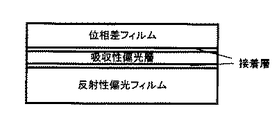
本発明の光学フィルム積層体は、吸収性偏光フィルムの一方の面に反射性偏光フィルム、他方の面に透明性フィルムを備える構成をとる。図1に本発明の光学フィルム積層体の代表的な構成図を示す。 The optical film laminate of the present invention has a configuration in which a reflective polarizing film is provided on one surface of an absorptive polarizing film and a transparent film is provided on the other surface. FIG. 1 shows a typical configuration diagram of the optical film laminate of the present invention.
以下、本発明を詳細に説明する。説明の便宜上、吸収性偏光フィルム、透明性偏光フィルム、反射性偏光フィルムの順に説明する。 Hereinafter, the present invention will be described in detail. For convenience of explanation, an absorptive polarizing film, a transparent polarizing film, and a reflective polarizing film will be described in this order.
[吸収性偏光フィルム]
本発明における吸収性偏光フィルムは、例えば、ポリマーフィルムに、二色性物質、例えばヨウ素を吸着させて、架橋、延伸、乾燥することによって得ることができる。この中でも、光透過率や偏光度に優れるものが好ましい。二色性物質を吸着させるポリマーフィルムとしては、例えば、PVA系フィルム、部分ホルマール化PVA系フィルム、エチレン・酢酸ビニル共重合体系部分ケン化フィルム、セルロース系フィルム等の親水性高分子フィルムがあげられ、これらの他にも、例えば、PVAの脱水処理物やポリ塩化ビニルの脱塩酸処理物等のポリエン配向フィルムも使用できる。これらの中でも、好ましくはPVA系フィルムである。また、偏光フィルムの厚みは通常は1〜80μmである。
[Absorptive polarizing film]
The absorptive polarizing film in the present invention can be obtained, for example, by adsorbing a dichroic substance such as iodine to a polymer film, followed by crosslinking, stretching and drying. Among these, those excellent in light transmittance and polarization degree are preferable. Examples of polymer films that adsorb dichroic substances include hydrophilic polymer films such as PVA films, partially formalized PVA films, ethylene / vinyl acetate copolymer partially saponified films, and cellulose films. Besides these, for example, polyene oriented films such as PVA dehydrated products and polyvinyl chloride dehydrochlorinated products can also be used. Among these, PVA film is preferable. Moreover, the thickness of a polarizing film is 1-80 micrometers normally.
吸収性偏光フィルムと反射偏光フィルムとは接着剤で接着され、吸収性偏光フィルムと透明性フィルムとは接着剤で接着されるのが通常である。接着剤としては、従来公知の接着剤や粘着剤等が使用できる。その種類は、例えば、前記各構成物の材質等によって適宜決定できる。接着剤としては、例えば、アクリル系重合体、シリコーン系ポリマー、ポリエステル、ポリウレタン、ポリエーテル、ポリビニルアルコール、合成ゴム等のポリマー製材料が挙げられる。特に、吸収性偏光フィルムとの接着性が特に良好なことから、ポリビニルアルコール系接着剤が好ましい。 The absorptive polarizing film and the reflective polarizing film are usually bonded with an adhesive, and the absorptive polarizing film and the transparent film are usually bonded with an adhesive. As the adhesive, conventionally known adhesives and pressure-sensitive adhesives can be used. The type can be determined as appropriate depending on, for example, the material of each component. Examples of the adhesive include polymer materials such as acrylic polymer, silicone polymer, polyester, polyurethane, polyether, polyvinyl alcohol, and synthetic rubber. In particular, a polyvinyl alcohol-based adhesive is preferred because of its particularly good adhesiveness with the absorbent polarizing film.
[透明性フィルム]
本発明における透明性フィルムは、水蒸気透過率は100〜500g/m2/dayである必要がある。透明性フィルムの水蒸気透過率が100g/m2/day未満であると、接着剤を介して積層体を構成したときに水蒸気が蒸散せずに接着性が乏しい。透明性フィルムの水蒸気透過率が500g/m2/dayを越えると、高湿度下で光学フィルム積層体が吸湿し、寸法変化を生じるため、液晶表示のゆがみを生じてしまう。なお、透明性フィルムは、液晶を透過した光の偏光状態を保持するために、低複屈折性の透明性フィルムであることが好ましい。本発明において低複屈折性とは、3次元方向(X、Y、Z)の屈折率差があらゆる方向において0.1以下であることをいう。また、透明性フィルムは、透明性を確保するために、ヘーズが1%以下であることが好ましい。
[Transparency film]
The transparent film in the present invention needs to have a water vapor transmission rate of 100 to 500 g / m 2 / day. When the water vapor transmission rate of the transparent film is less than 100 g / m 2 / day, the water vapor does not evaporate when the laminate is formed via an adhesive, resulting in poor adhesion. When the water vapor transmission rate of the transparent film exceeds 500 g / m 2 / day, the optical film laminate absorbs moisture under high humidity and causes dimensional changes, resulting in distortion of the liquid crystal display. The transparent film is preferably a low birefringence transparent film in order to maintain the polarization state of light transmitted through the liquid crystal. In the present invention, the low birefringence means that the refractive index difference in the three-dimensional direction (X, Y, Z) is 0.1 or less in all directions. The transparent film preferably has a haze of 1% or less in order to ensure transparency.
このような水蒸気透過率を備える透明性フィルムを、従来公知の透明性フィルムから適宜選んで使用すればよい。このような透明性フィルムの具体例として、トリアセチルセルロース等のセルロース、ポリエステル、ポリノルボルネン、ポリカーボネート、ポリアミド、ポリイミド、ポリエーテルスルホン、ポリスルホン、ポリスチレン、ポリオレフィン、アクリル、アセテート等の透明樹脂を挙げることができる。また、アクリル、ウレタン、アクリルウレタン、エポキシ、シリコーン等の熱硬化型樹脂または紫外線硬化型樹脂を挙げることができる。これらは一種類でもよいし、二種類以上を組み合わせて使用することもできる。この中でも、偏光特性や耐久性の点から、表面をアルカリ等でケン化処理したトリアセチルセルロース(以下「TAC」という。)フィルムが好ましい。TACフィルムを用いる場合、水蒸気透過率を確保するために20〜80μmの厚みで用いることが好ましい。 A transparent film having such a water vapor transmission rate may be appropriately selected from conventionally known transparent films. Specific examples of such a transparent film include transparent resins such as cellulose such as triacetyl cellulose, polyester, polynorbornene, polycarbonate, polyamide, polyimide, polyethersulfone, polysulfone, polystyrene, polyolefin, acrylic, and acetate. it can. Moreover, thermosetting resins or ultraviolet curable resins such as acrylic, urethane, acrylic urethane, epoxy, and silicone can be used. These may be used alone or in combination of two or more. Among these, a triacetyl cellulose (hereinafter referred to as “TAC”) film whose surface is saponified with an alkali or the like is preferable from the viewpoint of polarization characteristics and durability. When using a TAC film, it is preferable to use with a thickness of 20 to 80 μm in order to ensure water vapor permeability.
また、水蒸気透過特性を満たす他の樹脂の例として、特開2001−343529号公報(WO01/37007)に記載のポリマーのフィルムを使用してもよい。このポリマーとしては、例えば、側鎖に置換または非置換のイミド基を有する熱可塑性樹脂と、側鎖に置換または非置換のフェニル基ならびにニトリル基を有す熱可塑性樹脂を含有する樹脂組成物を使用することができる、例えば、イソブテンとN−メチルマレイミドからなる交互共重合体と、アクリロニトリル・スチレン共重合体とを有する樹脂組成物を挙げることができる。なお、前記ポリマーフィルムは、例えば、前記樹脂組成物の押出成形物であってもよい。 Moreover, you may use the film of the polymer as described in Unexamined-Japanese-Patent No. 2001-343529 (WO01 / 37007) as an example of other resin which satisfy | fills a water-vapor-permeation characteristic. Examples of the polymer include a resin composition containing a thermoplastic resin having a substituted or unsubstituted imide group in the side chain, and a thermoplastic resin having a substituted or unsubstituted phenyl group and a nitrile group in the side chain. Examples of the resin composition that can be used include an alternating copolymer of isobutene and N-methylmaleimide and an acrylonitrile / styrene copolymer. The polymer film may be, for example, an extruded product of the resin composition.
透明性フィルムは、1軸または2軸延伸加工されたフィルムであってもよい。延伸加工することにより、光学補償位相差フィルムとして使用することもできる。 The transparent film may be a uniaxial or biaxially stretched film. By stretching, it can also be used as an optical compensation retardation film.
図2に本発明における透明性フィルムを光学補償位相差フィルムとした場合の構成例を示す。光学補償位相差フィルムとは、液晶および吸収性偏光フィルムの角度による色相変化を補償するものであり、液晶ディスプレイの表示方式により異なる。例えば、垂直配向式液晶(VA型液晶の場合)、面内方向の位相差(Rd)が、40nm〜60nmであることが好ましく、厚み方向の位相差(Rth)が100〜150nmであることが好ましい。 FIG. 2 shows a configuration example in the case where the transparent film in the present invention is an optical compensation retardation film. The optical compensation retardation film compensates for a change in hue depending on the angle of the liquid crystal and the absorptive polarizing film, and differs depending on the display method of the liquid crystal display. For example, the vertical alignment type liquid crystal (in the case of VA type liquid crystal), the in-plane direction retardation (Rd) is preferably 40 to 60 nm, and the thickness direction retardation (Rth) is 100 to 150 nm. preferable.
なお、下記式において、nx,ny,nzは、前述と同様にX軸、Y軸、Z軸における屈折率であり、dはその膜厚を示す。
Rd=(nx−ny)・d
Rth=[[(nx+ny)/2]-nz]・d
In the following formula, nx, ny, and nz are the refractive indexes on the X axis, the Y axis, and the Z axis as described above, and d indicates the film thickness.
Rd = (nx−ny) · d
Rth = [[[(nx + ny) / 2] -nz] · d
上記の水蒸気透過特性と位相差機能発現を具備する素材の例としては、前記のトリアセチルセルロースのアセチル基を部分的にプロピオネートで置換した変性トリアセチルセルロースの延伸フィルムや、前記のイソブテンとN−メチルマレイミドからなる交互共重合体と、アクリロニトリル・スチレン共重合体とを有する樹脂組成物の延伸フィルムなどが挙げられる。このフィルムを用いる場合には、水蒸気透過率を確保するために5〜40μmの厚みで用いることが好ましい。 Examples of the material having the water vapor transmission characteristics and the retardation function expression include a stretched film of modified triacetyl cellulose in which the acetyl group of the triacetyl cellulose is partially substituted with propionate, and the isobutene and N- Examples thereof include a stretched film of a resin composition having an alternating copolymer composed of methylmaleimide and an acrylonitrile / styrene copolymer. When this film is used, it is preferably used in a thickness of 5 to 40 μm in order to ensure water vapor transmission rate.
[反射性偏光フィルム]
本発明における反射性偏光フィルムの水蒸気透過率は5〜20g/m2/dayである必要がある。反射性偏光フィルムの水蒸気透過率が5g/m2/day未満であると、接着剤を介して積層体を構成したときに水蒸気が蒸散せずに接着性が乏しい。反射性偏光フィルムの水蒸気透過率が20g/m2/dayを超えると、高湿度下で光学フィルム積層体が吸湿し、寸法変化を生じるため、液晶表示のゆがみを生じてしまう。
[Reflective polarizing film]
The water vapor transmission rate of the reflective polarizing film in the present invention needs to be 5 to 20 g / m 2 / day. When the water vapor transmission rate of the reflective polarizing film is less than 5 g / m 2 / day, the water vapor does not evaporate when the laminate is formed via an adhesive, resulting in poor adhesion. If the water vapor transmission rate of the reflective polarizing film exceeds 20 g / m 2 / day, the optical film laminate absorbs moisture under high humidity and causes dimensional changes, resulting in distortion of the liquid crystal display.
反射性偏光フィルムは、耐久性を良好にする観点から、1軸延伸多層積層フィルムであることが、好ましい。以下、この好ましい1軸延伸多層積層フィルムについて説明する。 The reflective polarizing film is preferably a uniaxially stretched multilayer laminated film from the viewpoint of improving durability. Hereinafter, this preferable uniaxially stretched multilayer laminated film will be described.
そもそも多層積層フィルムは、屈折率の低い層と高い層とを交互に多数積層したものであり、層間の構造的な光干渉によって、特定波長の光を選択的に反射または透過する光学干渉フィルムとすることができる。このような多層積層フィルムは、膜厚を徐々に変化させたり、異なる反射ピークを有するフィルムを貼り合せたりすることで金属を使用したフィルムと同等の高い反射率を得ることができる。この多層積層フィルムを1方向にのみ延伸することで、特定の偏光成分のみを反射する偏光反射フィルムを得ることができる。 In the first place, a multilayer laminated film is a laminate in which a large number of layers having a low refractive index and a layer having a high refractive index are alternately laminated, and an optical interference film that selectively reflects or transmits light of a specific wavelength by structural optical interference between the layers. can do. Such a multilayer laminated film can obtain a high reflectance equivalent to that of a film using metal by gradually changing the film thickness or by bonding films having different reflection peaks. By stretching the multilayer laminated film only in one direction, a polarization reflection film that reflects only a specific polarization component can be obtained.
層厚が0.05〜0.5μmの、相互に異なる屈折率を持った層を交互に重ねて構成される多層光学フィルムは、一方の層を構成する層と他方の層を構成する層の屈折率差と膜厚および積層数により特定の波長の光を反射する増反射といった現象がみられる。その反射波長は、下記の式で示される。
λ=2x((n1)x(d1)+(n2)x(d2))
ここで、λは反射波長(nm)、n1、n2はそれぞれの層の屈折率、d1、d2は、それぞれの層の厚み(nm)である。
A multilayer optical film having a layer thickness of 0.05 to 0.5 μm and having layers having different refractive indexes alternately stacked is composed of a layer constituting one layer and a layer constituting the other layer. There is a phenomenon such as increased reflection that reflects light of a specific wavelength depending on the refractive index difference, the film thickness, and the number of layers. The reflection wavelength is shown by the following formula.
λ = 2x ((n1) x (d1) + (n2) x (d2))
Here, λ is the reflection wavelength (nm), n1 and n2 are the refractive indexes of the respective layers, and d1 and d2 are the thicknesses (nm) of the respective layers.
特開平04−268505号公報に示されている通り、一方の層に正の応力光学係数をもった樹脂使用することで、1軸方向に延伸により複屈折に異方性を持たせ、特定の偏光成分のみを反射することができる。この原理を使用して、例えば、P偏光を反射し、S偏光を透過するといった反射偏光フィルムを設計することが出来る。そのときの望ましい複屈折性は下記の式で表される。
n1x>n2x、n1y=n2y
n1x、n2xはそれぞれの層の延伸方向の屈折率、n1y、n2yはそれぞれの層に延伸方向に直行する方向の屈折率である。
As shown in Japanese Patent Application Laid-Open No. 04-268505, by using a resin having a positive stress optical coefficient in one layer, birefringence is made anisotropic by stretching in a uniaxial direction. Only the polarization component can be reflected. Using this principle, for example, a reflective polarizing film that reflects P-polarized light and transmits S-polarized light can be designed. Desirable birefringence at that time is represented by the following equation.
n1x> n2x, n1y = n2y
n1x and n2x are refractive indexes in the extending direction of the respective layers, and n1y and n2y are refractive indexes in the direction perpendicular to the extending direction of the respective layers.
特表平9−506837号公報やWO01/47711号公報では、屈折率の高い層に屈折率の高いポリエチレン−2,6−ナフタレンジカルボキシレート(以下「PEN」と称することがある。)を使用し、屈折率の低い層に熱可塑性エラストマーを使用した2軸延伸フィルムや屈折率の高い層に屈折率の高いPENを使用し、屈折率の低い層にイソフタル酸を30mol%共重合したPENを使用した1軸延伸多層延伸フィルムが例示されている。これは、一方の層に正の応力光学係数を有する樹脂を使用し、他方の層に応力光学係数が非常に小さい(延伸による複屈折の発現が極めて小さい)樹脂を使用することで、特定の偏光のみを反射する反射偏光フィルムを例示したものである。しかし、これらの反射偏光フィルムは、厚みが135ミクロン程度厚く水蒸気透過特性が低いために、吸収型偏光フィルムとの貼り合せが困難であった。 In JP-A-9-506837 and WO01 / 47711, polyethylene-2,6-naphthalenedicarboxylate (hereinafter sometimes referred to as “PEN”) having a high refractive index is used for a layer having a high refractive index. Biaxially stretched film using a thermoplastic elastomer for the low refractive index layer, PEN having a high refractive index for the high refractive index layer, and PEN copolymerized with 30 mol% of isophthalic acid for the low refractive index layer. The uniaxially stretched multilayer stretched film used is illustrated. This is because a resin having a positive stress optical coefficient is used in one layer and a resin having a very low stress optical coefficient (extremely low birefringence due to stretching) is used in the other layer. The reflective polarizing film which reflects only polarized light is illustrated. However, since these reflective polarizing films are about 135 microns thick and have low water vapor transmission characteristics, it is difficult to bond them to the absorbing polarizing film.
1軸延伸フィルムを反射性偏光フィルムとして用いる場合、1軸延伸フィルムの延伸方向とフィルム面内方向を基準とする平面に対して平行な偏光成分について、波長400〜800nmの平均反射率が90%以上であり、かつ同平面に対して垂直な偏光成分について、波長400〜800nmの平均反射率が15%以下であることが好ましい。1軸延伸フィルムの延伸方向とフィルム面内方向を基準とする平面に対して平行な偏光成分について、波長400〜800nmの平均反射率が90%以下であると反射偏光フィルムとしての偏光反射性能が不十分であり、液晶ディスプレイなどの輝度向上フィルムのとして十分な性能を発現しないことから好ましくない。好ましくは95%以上、より好ましくは98%以上である。また、同平面に対して垂直な偏光成分について、波長400〜800nmの平均反射率が15%以上であると反射偏光フィルムとしての偏光透過率が低下するため、液晶ディスプレイなどの輝度向上フィルムとして性能が劣ることから好ましくない。好ましくは13%以下、より好ましくは10%以下である。 When a uniaxially stretched film is used as a reflective polarizing film, the average reflectance at a wavelength of 400 to 800 nm is 90% for a polarized component parallel to a plane based on the stretching direction of the uniaxially stretched film and the in-plane direction of the film. For the polarization component perpendicular to the same plane as described above, the average reflectance at a wavelength of 400 to 800 nm is preferably 15% or less. About the polarization component parallel to the plane based on the stretching direction of the uniaxially stretched film and the in-plane direction of the film, if the average reflectance at a wavelength of 400 to 800 nm is 90% or less, the polarization reflection performance as a reflective polarizing film is It is not preferable because it is insufficient and does not exhibit sufficient performance as a brightness enhancement film such as a liquid crystal display. Preferably it is 95% or more, More preferably, it is 98% or more. In addition, with respect to a polarized light component perpendicular to the same plane, if the average reflectance at a wavelength of 400 to 800 nm is 15% or more, the polarization transmittance as a reflective polarizing film is lowered, so that it can be used as a brightness enhancement film for liquid crystal displays and the like. Is not preferable because it is inferior. Preferably it is 13% or less, More preferably, it is 10% or less.
この1軸延伸フィルムでは、1軸延伸フィルムの延伸方向とフィルム面内方向を基準とする平面に対して平行な偏光成分について、波長400〜800nmの各波長における最大反射率と最小反射率の差が10%以内であり、かつ、同平面に対して垂直な偏光成分について、波長400〜800nmの各波長における最大反射率と最小反射率の差が10%以内であることが好ましい。上記偏光成分の最大反射率と最小反射率の差が10%以上であると、反射または、透過する光の色相のずれが生じるために液晶ディスプレイなどに使用に問題が生じることがあることから好ましくない。 In this uniaxially stretched film, the difference between the maximum reflectance and the minimum reflectance at each wavelength of 400 to 800 nm with respect to the polarization component parallel to the plane based on the stretching direction of the uniaxially stretched film and the film in-plane direction. And the difference between the maximum reflectance and the minimum reflectance at each wavelength of 400 to 800 nm is preferably within 10% for a polarized light component perpendicular to the same plane. It is preferable that the difference between the maximum reflectance and the minimum reflectance of the polarization component is 10% or more, because the hue of reflected or transmitted light may be shifted, which may cause problems in use for liquid crystal displays. Absent.
本発明における反射性偏光フィルムは少なくとも501層から構成されることが好ましい。層数が501層未満であると、波長400〜800nmにわたり上記の目的とする光学特性を満足することができない。積層数の上限は、生産性およびフィルムのハンドリング性など観点から、高々2001層であることが好ましい。 The reflective polarizing film in the present invention is preferably composed of at least 501 layers. If the number of layers is less than 501 layers, the above-mentioned optical characteristics as the objective cannot be satisfied over a wavelength range of 400 to 800 nm. The upper limit of the number of layers is preferably at most 2001 layers from the viewpoint of productivity and film handling.
第1の層および第2の層は、層間の光干渉によって選択的に光を反射するために、それぞれ1層の厚みが好ましくは0.05〜0.5μmである。多層光学フィルムの反射特性は、層数、屈折率差、層の厚みで決定される。本発明における1軸延伸多層積層フィルムが示す反射波長帯は、可視光域から近赤外線領域であることから、上記層厚の範囲とすることが必要である。層厚みが0.5μmを超えると反射帯域が赤外線領域になり反射偏光フィルムとして有用性が得られず好ましくない。0.05μm未満であると反射光は、反射帯域が紫外線領域になり、実質的に性能が得られなくなり好ましくない。 Each of the first layer and the second layer preferably has a thickness of 0.05 to 0.5 μm in order to selectively reflect light by optical interference between the layers. The reflection characteristics of the multilayer optical film are determined by the number of layers, refractive index difference, and layer thickness. Since the reflection wavelength band shown by the uniaxially stretched multilayer laminated film in the present invention is from the visible light region to the near infrared region, it is necessary to set the layer thickness within the above range. When the layer thickness exceeds 0.5 μm, the reflection band is in the infrared region, and the usefulness as a reflective polarizing film cannot be obtained. When the thickness is less than 0.05 μm, the reflected light is not preferable because the reflection band is in the ultraviolet region and the performance is not substantially obtained.
本発明における1軸延伸多層積層フィルムでは、第1の層の平均厚みに対する第2の層の平均厚みの比率が0.5〜5.0の範囲であることが好ましい。第1の層と第2の層の厚み比を変化させることにより層間の密着性を維持したまま、また使用する樹脂を変更することなく、1軸延伸多層積層フィルムの機械特性を調整することができる。第1の層の平均厚みに対する第2の層の平均厚みの比率が0.5以下であると1軸延伸多層積層フィルムの延伸方向に裂け易くなり好ましくない。より好ましい比率の下限は1.0であり、さらに好ましくは1.5である。一方で第1の層の平均厚みに対する第2の層の平均厚みの比率が5.0以上であると熱処理による配向緩和の差異に1軸延伸多層積層フィルムの厚みの変動が大きくなり好ましくない。より好ましい比率の下限は4.0であり、さらに好ましくは、3.5である。 In the uniaxially stretched multilayer laminated film of the present invention, the ratio of the average thickness of the second layer to the average thickness of the first layer is preferably in the range of 0.5 to 5.0. By changing the thickness ratio between the first layer and the second layer, the mechanical properties of the uniaxially stretched multilayer laminated film can be adjusted while maintaining the adhesion between the layers and without changing the resin used. it can. If the ratio of the average thickness of the second layer to the average thickness of the first layer is 0.5 or less, it is not preferable because it tends to tear in the stretching direction of the uniaxially stretched multilayer laminated film. The lower limit of the more preferable ratio is 1.0, and more preferably 1.5. On the other hand, if the ratio of the average thickness of the second layer to the average thickness of the first layer is 5.0 or more, the variation in the thickness of the uniaxially stretched multilayer laminated film becomes unfavorable due to the difference in orientation relaxation due to heat treatment. The lower limit of the more preferable ratio is 4.0, and more preferably 3.5.
また、光学多層フィルムは、上記の式(1)によって、屈折率、層数、層の厚みによって反射する波長が決まるが、積層された第1の層および第2の層のそれぞれが一定の厚みでは、特定の波長のみしか反射することができない。 In the optical multilayer film, the reflection wavelength is determined by the refractive index, the number of layers, and the thickness of the layer according to the above formula (1), but each of the laminated first and second layers has a constant thickness. Then, only a specific wavelength can be reflected.
従って、本発明における1軸延伸多層積層フィルムでは、第1の層および第2の層それぞれの最大厚みと最小厚みの比率が1.5〜5.0であることが好ましい。第1の層および第2の層は、段階的に変化してもよく、連続的に変化してもよい。このように積層された第1の層および第2の層のそれぞれが変化することで、より広い波長域の光を反射することができる。第1の層および第2の層それぞれの最大厚みと最小厚みの比率が1.5未満であると400〜800nmの波長域にわたり前述の目的となる反射特性をカバーできない。好ましい比率の下限は2.0であり、よりこのましくは2.5である。一方で、第1の層および第2の層それぞれの最大厚みと最小厚みの比率が5.0以上であると反射帯域が広がりすぎ、反射率が低下するために、前述の目的となる反射特性が得られない。好ましい比率の上限は4.0であり、よりこのましくは3.5である。また、このとき、積層構造として、段階的または、連続的に変化する多層構造の表層または、内部に0.5μm以上の層が1層以上存在してもよい。 Therefore, in the uniaxially stretched multilayer laminated film in the present invention, the ratio of the maximum thickness and the minimum thickness of each of the first layer and the second layer is preferably 1.5 to 5.0. The first layer and the second layer may change stepwise or may change continuously. By changing each of the first layer and the second layer laminated in this manner, light in a wider wavelength range can be reflected. When the ratio between the maximum thickness and the minimum thickness of each of the first layer and the second layer is less than 1.5, the above-mentioned reflection characteristics cannot be covered over the wavelength range of 400 to 800 nm. The lower limit of the preferred ratio is 2.0, more preferably 2.5. On the other hand, if the ratio between the maximum thickness and the minimum thickness of each of the first layer and the second layer is 5.0 or more, the reflection band is excessively widened and the reflectance is lowered. Cannot be obtained. The upper limit of the preferred ratio is 4.0, more preferably 3.5. At this time, as the laminated structure, there may be one or more layers of 0.5 μm or more in the surface layer of the multilayer structure that changes stepwise or continuously.
図3に、本発明における1軸延伸多層積層フィルムの反射率曲線の一例を示す。P偏光とは、フィルムの延伸方向とフィルム面と垂直方向を含む面内に平行な偏光成分であり、S偏光とは、フィルムの延伸方向とフィルム面と垂直方向を含む面内に垂直な偏光成分を示す。 In FIG. 3, an example of the reflectance curve of the uniaxial stretching multilayer laminated film in this invention is shown. P-polarized light is a polarized light component parallel to a plane including the film stretching direction and the direction perpendicular to the film surface, and S-polarized light is polarized light perpendicular to the film including the film stretching direction and the film surface perpendicular direction. Ingredients are shown.
本発明において、第1の層を構成する樹脂は、正の応力複屈折を有する熱可塑性樹脂であることが好ましい。
正の応力複屈折を有する熱可塑性樹脂としては、ポリエチレンナフタレート(PEN)およびその異性体(例えば、2,6−、1,4−、1,5−、2,7−、および2,3−PEN)、ポリアルキレンテレフタレート(例えば、ポリエチレンテレフタレート ポリブチレンテレフタレート、およびポリ−1,4−シクロヘキサンジメチレンテレフタレート)、ポリイミド(例えば、ポリアクリル酸イミド)、ポリエーテルイミド、ポリアルキレンポリマー(例えば、ポリエチレン、ポリプロピレン、ポリブチレン、ポリイソブチレン、およびポリ(4−メチル)ペンテン)、フッ素化ポリマー(例えば、ペルフルオロアルコキシ樹脂、ポリテトラフルオロエチレン、フッ素化エチレン−プロピレンコポリマー、ポリフッ化ビニリデン、およびポリクロロトリフルオロエチレン)、塩素化ポリマー(例えば、ポリ塩化ビニリデンおよびポリ塩化ビニル)、ポリスルホン、ポリエーテルスルホン、ポリアクリロニトリル、ポリアミド、シリコーン樹脂、エポキシ樹脂、ポリ酢酸ビニル、ポリエーテルアミド、アイオノマー樹脂、エラストマー(例えば、ポリブタジエン、ポリイソプレン、およびネオプレン)、ならびにポリウレタンなどがある。
In the present invention, the resin constituting the first layer is preferably a thermoplastic resin having positive stress birefringence.
Examples of thermoplastic resins having positive stress birefringence include polyethylene naphthalate (PEN) and its isomers (for example, 2,6-, 1,4-, 1,5-, 2,7-, and 2,3 -PEN), polyalkylene terephthalate (eg, polyethylene terephthalate, polybutylene terephthalate, and poly-1,4-cyclohexanedimethylene terephthalate), polyimide (eg, polyacrylimide), polyetherimide, polyalkylene polymer (eg, polyethylene) , Polypropylene, polybutylene, polyisobutylene, and poly (4-methyl) pentene), fluorinated polymers (eg, perfluoroalkoxy resins, polytetrafluoroethylene, fluorinated ethylene-propylene copolymers, polyvinylidene fluoride, and Polychlorotrifluoroethylene), chlorinated polymers (eg, polyvinylidene chloride and polyvinyl chloride), polysulfone, polyethersulfone, polyacrylonitrile, polyamide, silicone resin, epoxy resin, polyvinyl acetate, polyetheramide, ionomer resin, Elastomers (eg, polybutadiene, polyisoprene, and neoprene), polyurethane, and the like.
その中でも、応力複屈折の大きいポリエチレンナフタレート(PEN)およびその異性体(例えば、2,6−、1,4−、1,5−、2,7−、および2,3−PEN)や、ポリアルキレンテレフタレート(例えば、ポリエチレンテレフタレート ポリブチレンテレフタレート、およびポリ−1,4−シクロヘキサンジメチレンテレフタレート)などが好ましい。とりわけポリエチレンナフタレート(PEN)およびその異性体(例えば、2,6−、1,4−、1,5−、2,7−、および2,3−PEN)が好適である。 Among them, polyethylene naphthalate (PEN) having a high stress birefringence and its isomer (for example, 2,6-, 1,4-, 1,5-, 2,7-, and 2,3-PEN), Polyalkylene terephthalate (for example, polyethylene terephthalate, polybutylene terephthalate, and poly-1,4-cyclohexanedimethylene terephthalate) is preferable. Polyethylene naphthalate (PEN) and its isomers (for example, 2,6-, 1,4-, 1,5-, 2,7-, and 2,3-PEN) are particularly preferable.
また、第2の層を構成する樹脂は、熱可塑性樹脂であれば特に限定されない。例えば上記に挙げた熱可塑性樹脂に加え、アタクチックポリスチレン、ポリカーボネート、ポリメタクリレート(例えば、ポリイソブチルメタクリレート、ポリプロピルメタクリレート、ポリエチルメタクリレート、およびポリメチルメタクリレート)、ポリアクリレート(例えば、ポリブチルアクリレートおよびポリメチルアクリレート)、シンジオタクチックポリスチレン、シンジオタクチックポリ-α-メチルスチレン、シンジオタクチックポリジクロロスチレン、これらの任意のポリスチレンから成るコポリマーおよびブレンド、セルロース誘導体(例えば、エチルセルロース、酢酸セルロース、プロピオン酸セルロース、酢酸酪酸セルロース、およびニトロセルロース)などが挙げられる。 Moreover, the resin which comprises a 2nd layer will not be specifically limited if it is a thermoplastic resin. For example, in addition to the thermoplastic resins listed above, atactic polystyrene, polycarbonate, polymethacrylate (eg, polyisobutyl methacrylate, polypropyl methacrylate, polyethyl methacrylate, and polymethyl methacrylate), polyacrylate (eg, polybutyl acrylate and polymethacrylate) Methyl acrylate), syndiotactic polystyrene, syndiotactic poly-α-methylstyrene, syndiotactic polydichlorostyrene, copolymers and blends of any of these polystyrenes, cellulose derivatives (eg ethyl cellulose, cellulose acetate, cellulose propionate) , Cellulose acetate butyrate, and nitrocellulose).
特に第2の層として、正の応力複屈折を有する熱可塑性樹脂を使用する場合には、第1の層を構成する熱可塑性樹脂の融点よりも15〜60℃低いことが好ましい。その中でも、層間密着性の観点から第1の層にとりわけ好適なポリエチレンナフタレート(PEN)およびその異性体(例えば、2,6−、1,4−、1,5−、2,7−、および2,3−PEN)の融点よりも15〜60℃低いPENのコポリマー(例えば、2,6−、1,4−、1,5−、2,7−、および/または2,3−ナフタレンジカルボン酸もしくはそれらのエステルと、(a)テレフタル酸もしくはそのエスデル、(b)イソフタル酸もしくはそのエステル、(c)フタル酸もしくはそのエステル、(d)アルカングリコール、(e)シクロアルカングリコール(例えば、シクロヘキサンジメタノールジオール)、(f)アルカンジカルボン酸、および/または(g)シクロアルカンジカルボン酸(例えば、シクロヘキサンジカルボン酸)とのコポリマー)、ポリアルキレンテレフタレートのコポリマー(例えば、テレフタル酸もしくはそのエステルと、(a)ナフタレンジカルボン酸もしくはそのエステル、(b)イソフタル酸もしくはそのエステル、(c)フタル酸もしくはそのエステル、(d)アルカングリコール、(e)シクロアルカングリコール(例えば、シクロヘキサンジメタノールジオール)、(f)アルカンジカルボン酸、および/または(g)シクロアルカンジカルボン酸(例えば、シクロヘキサンジカルボン酸)とのコポリマー)、スチレンコポリマー(例えば、スチレン−ブタジエンコポリマーおよびスチレン−アクリロニトリルコポリマー)、ならびに4,4’−二安息香酸とエチレングリコールとのコポリマーなど、のコポリマーなどが挙げられる。 In particular, when a thermoplastic resin having positive stress birefringence is used as the second layer, it is preferably 15 to 60 ° C. lower than the melting point of the thermoplastic resin constituting the first layer. Among them, polyethylene naphthalate (PEN) particularly suitable for the first layer from the viewpoint of interlayer adhesion and isomers thereof (for example, 2,6-, 1,4-, 1,5-, 2,7-, And copolymers of PEN (eg, 2,6-, 1,4-, 1,5-, 2,7- and / or 2,3-naphthalene) which are 15-60 ° C. below the melting point of 2,3-PEN) A dicarboxylic acid or an ester thereof, (a) terephthalic acid or esdel thereof, (b) isophthalic acid or an ester thereof, (c) phthalic acid or an ester thereof, (d) an alkane glycol, (e) a cycloalkane glycol (for example, Cyclohexanedimethanol diol), (f) alkanedicarboxylic acid, and / or (g) cycloalkanedicarboxylic acid (eg, cyclohexanedicarboxylic acid). Copolymer), polyalkylene terephthalate copolymer (for example, terephthalic acid or its ester, (a) naphthalene dicarboxylic acid or its ester, (b) isophthalic acid or its ester, (c) phthalic acid or its ester , (D) alkane glycol, (e) cycloalkane glycol (eg, cyclohexanedimethanol diol), (f) alkane dicarboxylic acid, and / or (g) a copolymer with cycloalkane dicarboxylic acid (eg, cyclohexanedicarboxylic acid)) , Styrene copolymers (eg, styrene-butadiene copolymers and styrene-acrylonitrile copolymers), and copolymers of 4,4′-dibenzoic acid and ethylene glycol.
その中でも特に、第1の層を構成する樹脂は、主たる繰返し単位がエチレン−2,6−ナフタレンジカルボキシレート成分からなるポリエステルが好ましく、第2の層を構成する樹脂は、融点が210〜255℃である主たる繰返し単位がエチレン−2,6−ナフタレンジカルボキシレート成分からなるポリエステルが最も好ましい。 Among them, in particular, the resin constituting the first layer is preferably a polyester whose main repeating unit is an ethylene-2,6-naphthalenedicarboxylate component, and the resin constituting the second layer has a melting point of 210 to 255. Most preferred are polyesters in which the main repeat unit at 0 ° C comprises an ethylene-2,6-naphthalenedicarboxylate component.
以下、本発明において好適に用いられる1軸延伸多層積層フィルムについて詳述する。
[第1の層]
第1の層を構成する樹脂は、好ましくは融点が260〜270℃のポリエステル、さらに好ましくは主たる繰返し単位がエチレン−2,6−ナフタレンジカルボキシレート成分からなるポリエステルである。後述の第2の層を構成するポリエステルよりも融点を高度に維持できることから、ホモポリエチレン−2,6−ナフタレンジカルボキシレートまたは繰返し単位の95モル%以上がエチレン−2,6−ナフタレンジカルボキシレート成分からなる共重合ポリエチレン−2,6−ナフタレンジカルボキシレートであることが好ましい。エチレン−2,6−ナフタレンジカルボキシレート成分のモル数が繰返し単位の95モル%未満だと、融点が低下し、後述の第2の層を構成するポリエステルとの融点差が得られがたく、結果として、多層延伸フィルムに十分な屈折率差を付与しがたい。これらの中でも、融点を高度に維持できることから、ホモポリエチレン−2,6−ナフタレンジカルボキシレートが好ましい。エチレン−2,6−ナフタレンジカルボキシレート成分以外の共重合成分としては、イソフタル酸、2,7−ナフタレンジカルボン酸のような他の芳香族カルボン酸;アジピン酸、アゼライン酸、セバシン酸、デカンジカルボン酸等の如き脂肪族ジカルボン酸;シクロヘキサンジカルボン酸の如き脂環族ジカルボン酸等の酸成分や、ブタンジオール、ヘキサンジオール等の如き脂肪族ジオール;シクロヘキサンジメタノールの如き脂環族ジオール等、グリコール成分を好ましく挙げることができる。
Hereinafter, the uniaxially stretched multilayer laminated film suitably used in the present invention will be described in detail.
[First layer]
The resin constituting the first layer is preferably a polyester having a melting point of 260 to 270 ° C., more preferably a polyester whose main repeating unit is an ethylene-2,6-naphthalenedicarboxylate component. Homopolyethylene-2,6-naphthalenedicarboxylate or 95 mol% or more of the repeating unit is ethylene-2,6-naphthalenedicarboxylate because the melting point can be maintained higher than that of the polyester constituting the second layer described later. A copolymerized polyethylene-2,6-naphthalenedicarboxylate composed of components is preferred. When the number of moles of the ethylene-2,6-naphthalenedicarboxylate component is less than 95 mol% of the repeating unit, the melting point is lowered, and it is difficult to obtain a difference in melting point from the polyester constituting the second layer described later. As a result, it is difficult to give a sufficient refractive index difference to the multilayer stretched film. Among these, homopolyethylene-2,6-naphthalenedicarboxylate is preferable because the melting point can be maintained at a high level. Examples of copolymer components other than the ethylene-2,6-naphthalenedicarboxylate component include other aromatic carboxylic acids such as isophthalic acid and 2,7-naphthalenedicarboxylic acid; adipic acid, azelaic acid, sebacic acid, decanedicarboxylic acid Aliphatic dicarboxylic acids such as acids; Acid components such as alicyclic dicarboxylic acids such as cyclohexanedicarboxylic acid; Aliphatic diols such as butanediol and hexanediol; Glycol components such as alicyclic diols such as cyclohexanedimethanol Can be preferably mentioned.
ところで、第1の層を構成する樹脂の融点は、260〜270℃の範囲であることが、後述の第2の層を構成する樹脂との融点差を比較的大きくできることから必要である。第1の層を構成する樹脂の融点が下限よりも低いと、第2の層を構成する樹脂との融点差が小さくなり、結果として、得られる多層延伸フィルムに十分な屈折率差を付与することが困難になる。なお、共重合していないポリエチレン−2,6−ナフタレンジカルボキシレートの融点は、通常267℃近傍である。 By the way, it is necessary for the melting point of the resin constituting the first layer to be in the range of 260 to 270 ° C. because the melting point difference from the resin constituting the second layer described later can be relatively large. When the melting point of the resin constituting the first layer is lower than the lower limit, the melting point difference from the resin constituting the second layer is reduced, and as a result, a sufficient refractive index difference is imparted to the resulting multilayer stretched film. It becomes difficult. The melting point of uncopolymerized polyethylene-2,6-naphthalenedicarboxylate is usually around 267 ° C.
[第2の層]
第2の層を構成するポリエステルは、融点が210〜255℃の範囲であり、かつ第1の層のポリエステルの融点より15〜60℃低いポリエステルであることが好ましい。さらに好ましくは主たる繰返し単位がエチレン−2,6−ナフタレンジカルボキシレート単位からなるポリエステルである。ポリエステルは2軸延伸における製膜性の観点から、結晶性ポリエステルであることが必要である。また、前述の第1の層を構成するポリエステルよりも融点を低くできることから、繰返し単位の75〜97モル%がエチレン−2,6−ナフタレンジカルボキシレート単位からなり、繰返し単位の3〜25モル%がエチレン−2,6−ナフタレンジカルボキシレート以外の繰返し単位からなる共重合ポリエチレン−2,6−ナフタレンジカルボキシレートである。エチレン−2,6−ナフタレンジカルボキシレート単位のモル数が繰返し単位の75モル%未満であるか、エチレン−2,6−ナフタレンジカルボキシレート以外の繰返し単位のモル数が25モル%を超えると、実質的にポリマーが非晶性を示し、2軸延伸での製膜性が低下し、かつ前述の第1の層を構成するポリエステルとの組成が大きく異なり、層間の密着性が低下しやすい。他方、エチレン−2,6−ナフタレンジカルボキシレート単位のモル数が繰返し単位の97モル%を超えるかエチレン−2,6−ナフタレンジカルボキシレート以外の繰返し単位のモル数が3モル%未満だと、前述の第1の層を構成するポリエステルとの融点差が小さくなり、結果として、多層延伸フィルムに十分な反射率を付与することが困難となる。エチレン−2,6−ナフタレンジカルボキシレート以外の繰返し単位を構成するモノマー成分としては、イソフタル酸、2,7−ナフタレンジカルボン酸のような他の芳香族カルボン酸;アジピン酸、アゼライン酸、セバシン酸、デカンジカルボン酸等の如き脂肪族ジカルボン酸;シクロヘキサンジカルボン酸の如き脂環族ジカルボン酸等の酸成分や、ブタンジオール、ヘキサンジオール等の如き脂肪族ジオール;シクロヘキサンジメタノールの如き脂環族ジオール等、グリコール成分を好ましく挙げることができる。これらの中でも、比較的、延伸性を維持しながら融点を低下させやすいことからテレフタル酸またはイソフタル酸が好ましい。
[Second layer]
The polyester constituting the second layer is preferably a polyester having a melting point in the range of 210 to 255 ° C. and 15 to 60 ° C. lower than the melting point of the polyester in the first layer. More preferred is a polyester in which the main repeating unit is composed of ethylene-2,6-naphthalenedicarboxylate units . The polyester is required to be a crystalline polyester from the viewpoint of film forming property in biaxial stretching. Moreover, because it can lower melting point than the polyester constituting the first layer described above, 75 to 97 mole% of repeating units consist of ethylene-2,6-naphthalene dicarboxylate units, 3-25 mol of repeating units % Is a copolymerized polyethylene-2,6-naphthalenedicarboxylate composed of repeating units other than ethylene-2,6-naphthalenedicarboxylate . Or the number of moles of ethylene 2,6-naphthalene dicarboxylate units is less than 75 mol% of the repeating units, the number of moles of repeating units other than ethylene 2,6-naphthalene dicarboxylate is more than 25 mol% The polymer is substantially amorphous, the film-forming property by biaxial stretching is lowered, and the composition of the polyester constituting the first layer is greatly different, and the adhesion between the layers tends to be lowered. . On the other hand, when the number of moles of ethylene-2,6-naphthalene dicarboxylate unit exceeds 97 mole% of the repeating unit or the number of moles of repeating units other than ethylene-2,6-naphthalenedicarboxylate is less than 3 mole%. The melting point difference from the polyester constituting the first layer becomes small, and as a result, it becomes difficult to give sufficient reflectivity to the multilayer stretched film. As the monomer component constituting the ethylene-2,6-naphthalene dicarboxylate rate other than repeating units, isophthalic acid, 2,7-naphthalenedicarboxylic other aromatic carboxylic acids such as dicarboxylic acid; adipic acid, azelaic acid, Aliphatic dicarboxylic acids such as sebacic acid and decanedicarboxylic acid; acid components such as alicyclic dicarboxylic acids such as cyclohexanedicarboxylic acid; aliphatic diols such as butanediol and hexanediol; and alicyclic groups such as cyclohexanedimethanol Preferable examples include glycol components such as diols. Among these, terephthalic acid or isophthalic acid is preferable because it is relatively easy to lower the melting point while maintaining stretchability.
ところで、第2の層を構成するポリエステルの融点は、210〜255℃の範囲であることが、前述の第1の層を構成する樹脂との融点差を比較的大きくできることから好ましい。第2の層を構成する樹脂の融点が上限よりも高いと、第1の層を構成する樹脂との融点差が小さくなり、結果として、得られる多層延伸フィルムに十分な屈折率差を付与することが困難になる。一方、第2の層を構成する樹脂の融点が下限よりも低くするには、第1の層を構成する樹脂との組成が大きく変更することになり、得られる1軸延伸多層積層フィルムに十分な層間の密着性を付与することが困難になる。なお、第2の層を構成する樹脂の融点は、フィルムにする前の段階から低い必要はなく、延伸処理後に低くなっていれば良い。例えば、ホモポリエチレン−2,6−ナフタレンジカルボキシレートとそれ以外の他のポリエステルとを用意し、これらを溶融混練時にエステル交換させたものであってもよいことは容易に理解されるであろう。 Incidentally, the melting point of the polyester constituting the second layer is preferably in the range of 210 to 255 ° C., since the melting point difference from the resin constituting the first layer can be relatively large. When the melting point of the resin constituting the second layer is higher than the upper limit, the melting point difference from the resin constituting the first layer is reduced, and as a result, a sufficient refractive index difference is imparted to the resulting multilayer stretched film. It becomes difficult. On the other hand, in order for the melting point of the resin constituting the second layer to be lower than the lower limit, the composition with the resin constituting the first layer is greatly changed, which is sufficient for the obtained uniaxially stretched multilayer laminated film. It becomes difficult to provide adhesion between layers. Note that the melting point of the resin constituting the second layer does not need to be low from the stage before forming the film, and may be low after the stretching treatment. For example, it will be easily understood that homopolyethylene-2,6-naphthalene dicarboxylate and other polyesters may be prepared and transesterified at the time of melt kneading. .
[積層方法]
本発明における1軸延伸多層積層フィルムでは、第1の層および第2の層それぞれの最大厚みと最小厚みの比率が1.5〜5.0であることが好ましい。第1の層および第2の層は、段階的に変化してもよく、連続的に変化してもよい。このように積層された第1の層および第2の層のそれぞれが変化することで、より広い波長域の光を反射することができる。また、積層体の表層や中間層に0.5μm以上の厚膜層が存在してもよい。
[Lamination method]
In the uniaxially stretched multilayer laminated film of the present invention, the ratio of the maximum thickness and the minimum thickness of each of the first layer and the second layer is preferably 1.5 to 5.0. The first layer and the second layer may change stepwise or may change continuously. By changing each of the first layer and the second layer laminated in this manner, light in a wider wavelength range can be reflected. Further, a thick film layer of 0.5 μm or more may be present on the surface layer or intermediate layer of the laminate.
この1軸延伸多層積層フィルムにおける、多層構造を積層する方法は特に限定されないが、例えば、第1の層用ポリエステルを251層、第2の層用ポリエステルを250層に分岐させた第1の層と第2の層が交互に積層され、その流路が連続的に1〜3倍までに変化する多層フィードブロック装置を使用する方法や、多層フィードブロック装置により、201層の均一な層を積層しておき、その積層された流動体をさらに1.0:1.3:2.0の比で積層された面に垂直に3分岐したのち再び積層して601層にするといった方法もある。また、両者を組み合わせた方向も考えられる。 The method for laminating the multilayer structure in this uniaxially stretched multilayer laminated film is not particularly limited. For example, the first layer in which the first layer polyester is branched into 251 layers and the second layer polyester is branched into 250 layers. And a second layer are alternately stacked, and a uniform feed layer of 201 layers is stacked by a method using a multi-layer feed block device in which the flow path continuously changes by 1 to 3 times or a multi-layer feed block device. In addition, there is a method in which the laminated fluid is further branched into three perpendicularly to the laminated surface at a ratio of 1.0: 1.3: 2.0, and then laminated again to form 601 layers. Moreover, the direction which combined both is also considered.
[1軸延伸多層積層フィルム]
本発明における1軸延伸多層積層フィルムは、上述の第1の層および第2の層を、交互に少なくとも合計501層積層したものである。なお、本発明における1軸延伸多層積層フィルムは、前述のとおり、目的とする反射偏光フィルムとしての光学特性を満足するために、少なくとも1軸方向に延伸されている。このとき、延伸方向は、縦方向であっても、横方向であってもよい。また、光学特性を満足される範囲で、2軸延伸することや、多段延伸などを付与してもよい。また、延伸方法としては、棒状ヒータによる加熱延伸、ロール加熱延伸、テンター延伸など公知の延伸方法を用いることができるが、ロールとの接触によるキズの低減や延伸速度などの観点から、テンター延伸が好ましい。
[Uniaxially stretched multilayer laminated film]
The uniaxially stretched multilayer laminated film in the present invention is obtained by alternately laminating at least a total of 501 layers of the first layer and the second layer described above. In addition, as described above, the uniaxially stretched multilayer laminated film in the present invention is stretched in at least a uniaxial direction in order to satisfy the optical characteristics as the target reflective polarizing film. At this time, the stretching direction may be the longitudinal direction or the lateral direction. Moreover, you may provide biaxial stretching, multistage stretching, etc. in the range with which an optical characteristic is satisfied. In addition, as a stretching method, a known stretching method such as heat stretching with a rod heater, roll heating stretching, and tenter stretching can be used, but from the viewpoint of reduction of scratches due to contact with the roll and stretching speed, tenter stretching is performed. preferable.
延伸方向については、特に限定されないが、一般に吸収性偏光フィルムは、機械方向に延伸して製造することから、ロール状態での貼り合せが可能になることから、1軸延伸多層積層フィルムについても機械方向に延伸したものが好ましい。 The stretching direction is not particularly limited, but in general, the absorbent polarizing film is manufactured by stretching in the machine direction, and thus can be bonded in a roll state. Those stretched in the direction are preferred.
特に、本発明における1軸延伸多層積層フィルムは、層間の密着性及び2軸延伸加工の製膜性を確保する観点から、第1の層、第2の層ともに、正の応力光係数を示す結晶性樹脂を使用し、かつ第2の層の樹脂は、延伸後には、少なくとも部分的に溶融されて配向が緩和されていることが好ましい。このようにして得られた1軸延伸多層積層フィルムは、DSC(示差走査熱量計)で測定される融点が2つ以上存在し、かつそれらの融点か5℃以上異なることが好ましい。ここで、測定される融点は、高融点側が高屈折率を示す第1の層であり、低融点側は、低屈折率を示す第2の層であることは容易に想像がつくであろう。また、さらに好ましくは、延伸後に第2の層は少なくとも部分的に溶融されているために、DSCで測定される結晶化ピークが150℃〜220℃の範囲に存在することが好ましい。結晶化ピークが150℃未満であると、フィルムの延伸時に一方の層が急激に結晶化するために製膜時の製膜性が低下したり、膜質の均質性が低下しやすく、結果として、色相の斑などが発生することがあり好ましくない。他方、結晶化ピークが220℃以上であると、熱固定処理で第二の層を融解するときに、結晶化が同時に起こり、十分な屈折率差を発現させ難くなり好ましくない。 In particular, the uniaxially stretched multilayer laminated film in the present invention exhibits a positive stress light coefficient for both the first layer and the second layer from the viewpoint of ensuring adhesion between layers and film-formability of biaxial stretching. It is preferable that a crystalline resin is used and the resin of the second layer is at least partially melted and relaxed in orientation after stretching. The uniaxially stretched multilayer laminated film thus obtained preferably has two or more melting points measured by DSC (differential scanning calorimeter), and the melting points thereof are preferably different by 5 ° C. or more. Here, it can be easily imagined that the measured melting point is the first layer exhibiting a high refractive index on the high melting point side, and the second layer exhibiting the low refractive index on the low melting point side. . More preferably, since the second layer is at least partially melted after stretching, the crystallization peak measured by DSC is preferably in the range of 150 ° C to 220 ° C. When the crystallization peak is less than 150 ° C., one of the layers rapidly crystallizes when the film is stretched, so that the film-forming property at the time of film formation is reduced, or the homogeneity of the film quality is likely to be reduced. It is not preferable because hue spots may occur. On the other hand, if the crystallization peak is 220 ° C. or higher, crystallization occurs at the same time when the second layer is melted by heat setting treatment, and it is difficult to express a sufficient refractive index difference.
このように、本発明における1軸延伸多層積層フィルムは、ともに結晶性を示す第一の層の樹脂と第二の層の樹脂を延伸することによって、均質な膜質のフィルムが得られ、かつ延伸工程の後に第二の層を融解することで、層間密着性を向上させることと同時に反射性能を向上させることができる。従って、本発明における1軸延伸多層積層フィルムでは、DSCによる結晶ピークが150℃〜220℃に存在し、融点差が5℃以上異なる2つ以上の融解ピークが観測される1軸延伸多層積層フィルムが好ましい。 As described above, the uniaxially stretched multilayer laminated film in the present invention is obtained by stretching the resin of the first layer and the resin of the second layer, both of which exhibit crystallinity, and a film having a uniform film quality is obtained and stretched. By melting the second layer after the process, the interlayer adhesion can be improved and simultaneously the reflection performance can be improved. Therefore, in the uniaxially stretched multilayer laminate film of the present invention, a uniaxially stretched multilayer laminate film in which a crystal peak by DSC exists at 150 ° C. to 220 ° C., and two or more melting peaks different in melting point difference by 5 ° C. or more are observed. Is preferred.
また、本発明における1軸延伸多層積層フィルムは、延伸処理された方向の破断強度は、それぞれ100MPa以上であることが好ましい。破断強度が100MPa未満だと、多層延伸フィルムの加工時における取り扱い性が低下したり、製品にしたときの耐久性が低下したりして好ましくない。また、破断強度が100MPa以上であると、フィルムの腰が強くなり、巻取り性が向上するという利点もある。好ましい破断強度は、縦方向が150MPa以上、特に200MPa以上で、横方向が150MPa以上、特に200MPa以上である。また、縦方向と横方向の強度比は、3以下であることが耐引裂き性を十分に具備できることから好ましい。特に縦方向と横方向の強度比が2以下であると、さらに耐引裂き性を向上できることから好ましい。破断強度の上限は、特に限定はされないが、延伸工程の安定性を維持する観点から、高々500MPaであることが好ましい。 The uniaxially stretched multilayer laminated film in the present invention preferably has a breaking strength in the stretched direction of 100 MPa or more. When the breaking strength is less than 100 MPa, the handleability during processing of the multilayer stretched film is lowered, and the durability when it is made into a product is lowered, which is not preferable. Further, when the breaking strength is 100 MPa or more, there is an advantage that the stiffness of the film becomes strong and the winding property is improved. The preferred breaking strength is 150 MPa or more in the longitudinal direction, particularly 200 MPa or more, and 150 MPa or more, particularly 200 MPa or more in the transverse direction. In addition, the strength ratio in the longitudinal direction and the transverse direction is preferably 3 or less because tear resistance can be sufficiently obtained. In particular, the strength ratio in the longitudinal direction and the transverse direction is preferably 2 or less because tear resistance can be further improved. The upper limit of the breaking strength is not particularly limited, but is preferably at most 500 MPa from the viewpoint of maintaining the stability of the stretching process.
また、本発明における1軸延伸多層積層フィルムは、ポリエチレン−2,6−ナフタレンジカルボキシレートを主成分とすることから、特に熱寸法安定性が高いことが特徴であり、とりわけ加工プロセスにおいて、160℃以上の高温を必要とする場合にも十分に対応することができる。このフィルムの延伸処理された方向(製膜方向および幅方向)の150℃で30分間処理したときの熱収縮率が、それぞれ好ましくは5.0%以下、さらに好ましくは1.5%以下、特に好ましくは1.0%以下である。また、本発明における1軸延伸多層積層フィルムの200℃で10分間処理したときの製膜方向および幅方向の熱収縮率は、それぞれ好ましくは3.0%以下、さらに好ましくは2.0%以下、特に好ましくは1.5%以下である。 In addition, the uniaxially stretched multilayer laminated film in the present invention is characterized by particularly high thermal dimensional stability since it mainly comprises polyethylene-2,6-naphthalenedicarboxylate. Even when a high temperature of ℃ or higher is required, it can sufficiently cope. The heat shrinkage rate when treated for 30 minutes at 150 ° C. in the direction in which the film was stretched (film-forming direction and width direction) is preferably 5.0% or less, more preferably 1.5% or less, particularly preferably Preferably it is 1.0% or less. In addition, the heat shrinkage rate in the film forming direction and the width direction when the uniaxially stretched multilayer laminated film in the present invention is treated at 200 ° C. for 10 minutes is preferably 3.0% or less, more preferably 2.0% or less. Especially preferably, it is 1.5% or less.
[易接着層]
本発明における1軸延伸多層積層フィルムは、吸収性偏光フィルムのとの接着性向上のために、1軸延伸多層積層フィルムの少なくとも片面に、易接着層を設けてもよい。この易接着層は、特に限定はされないが、PVA系接着剤への接着性が良好なことから、PVA系の樹脂を含有する易接着層が好ましい。より好ましくは、1軸延伸多層積層フィルムとの接着性を確保すると同時に巻き取り性も確保するといった観点から、(A)コポリエステル、(B)ポリビニルアルコール、(C)微粒子、及び(D)架橋剤の成分を含有するものが好ましい。下記に最も好ましい例を詳述する。
[Easily adhesive layer]
In the present invention, the uniaxially stretched multilayer laminate film may be provided with an easy-adhesion layer on at least one side of the uniaxially stretched multilayer laminate film in order to improve the adhesion with the absorbent polarizing film. Although this easy-adhesion layer is not specifically limited, Since the adhesiveness to a PVA-type adhesive agent is favorable, the easy-adhesion layer containing PVA-type resin is preferable. More preferably, from the viewpoint of ensuring the adhesiveness with the uniaxially stretched multilayer laminated film and at the same time ensuring the winding property, (A) copolyester, (B) polyvinyl alcohol, (C) fine particles, and (D) cross-linking What contains the component of an agent is preferable. The most preferred example is described in detail below.
本発明における易接着層の最も好適な例としては、(A)コポリエステル30〜80重量部、(B)ポリビニルアルコール15〜45重量部、(C)微粒子3〜25重量部、(D)架橋剤5〜20重量部の組成比率の塗剤が挙げられる。(A)成分の割合が30重量部未満では1軸延伸多層積層フィルムとの接着性が不足し、一方80重量部を超えると吸収性偏光フィルム(PVAフィルム)との接着性が低下するので好ましくない。(B)成分の割合が15重量部未満ではインク受像層との接着性が不足し、一方45重量部を超えると耐ブロッキング性が低下するので好ましくない。また、(C)成分の割合が3重量部未満ではフイルムの滑性(搬送性)が不足し、一方25重量部をこえると削れ性が低下するので好ましくない。(D)成分の割合が5重量部未満では吸収性偏光フィルム(PVAフィルム)との接着性が不足し、一方20重量部を超えると耐ブロッキング性の低下、ポリエステルフィルムとの接着性が低下するため好ましくない。(D)架橋剤としては下記式で表される化合物を好ましく用いることができる。 The most suitable examples of the easy-adhesion layer in the present invention include (A) 30 to 80 parts by weight of copolyester, (B) 15 to 45 parts by weight of polyvinyl alcohol, (C) 3 to 25 parts by weight of fine particles, and (D) crosslinking. Examples thereof include a coating agent having a composition ratio of 5 to 20 parts by weight of the agent. When the proportion of the component (A) is less than 30 parts by weight, the adhesiveness with the uniaxially stretched multilayer laminated film is insufficient, and when it exceeds 80 parts by weight, the adhesiveness with the absorbent polarizing film (PVA film) is decreased. Absent. If the proportion of the component (B) is less than 15 parts by weight, the adhesion to the ink image-receiving layer is insufficient. On the other hand, if it exceeds 45 parts by weight, the blocking resistance decreases, which is not preferable. On the other hand, if the proportion of the component (C) is less than 3 parts by weight, the slipperiness (conveyability) of the film is insufficient. When the proportion of the component (D) is less than 5 parts by weight, the adhesiveness with the absorbent polarizing film (PVA film) is insufficient, while when it exceeds 20 parts by weight, the blocking resistance is lowered and the adhesiveness with the polyester film is lowered. Therefore, it is not preferable. (D) As the crosslinking agent, a compound represented by the following formula can be preferably used.

本発明における易接着層は、その表面エネルギーが、好ましくは50〜65dyne/cm、さらに好ましくは52〜60dyne/cmである。表面エネルギーが50dyne/cm未満であると、親水性である吸収性偏光フィルムとの接着性が不良となり、65dyne/cmを超えると基体である反射性偏光フィルムとの密着性が不足したり、塗膜の耐湿性が不足することがあるため好ましくない。 The easily adhesive layer in the present invention has a surface energy of preferably 50 to 65 dyne / cm, more preferably 52 to 60 dyne / cm. If the surface energy is less than 50 dyne / cm, the adhesion to the hydrophilic absorbing polarizing film becomes poor. If the surface energy exceeds 65 dyne / cm, the adhesion to the reflective polarizing film as the substrate is insufficient. This is not preferable because the moisture resistance of the film may be insufficient.
表面エネルギーが50〜65dyne/cmの塗膜は、上述の塗剤を、例えば0.02〜1μmの厚さで積層することにより得ることができる。 A coating film having a surface energy of 50 to 65 dyne / cm can be obtained by laminating the above-mentioned coating agent with a thickness of, for example, 0.02 to 1 μm.
易接着層は、前記微粒子を含有してもよく、塗膜表面の中心線平均粗さ(Ra)が10nm〜250nmの範囲にあることが、フィルムの耐ブロッキング性や搬送性が良好となるため好ましい。このようなRaを有する塗膜は、例えば塗膜成分として前記微粒子を前記の割合で用いることにより得ることができる。 The easy-adhesion layer may contain the fine particles, and the center line average roughness (Ra) of the coating film surface is in the range of 10 nm to 250 nm, because the film has good blocking resistance and transportability. preferable. Such a coating film having Ra can be obtained, for example, by using the fine particles as a coating film component in the above ratio.
本発明においては塗膜を形成する成分として、上記の成分以外にオキサゾリン樹脂、エポキシ樹脂、メラミン樹脂等の他の樹脂、帯電防止剤、着色剤、界面活性剤、紫外線吸収剤等を使用することができる。 In the present invention, in addition to the above components, other resins such as an oxazoline resin, an epoxy resin, and a melamine resin, an antistatic agent, a colorant, a surfactant, and an ultraviolet absorber are used as components for forming a coating film. Can do.
塗布方法としては、公知の任意の塗布法が適用できる。例えばロールコート法、グラビアコート法、ロールブラッシュ法、スプレーコート法、エアーナイフコート法、含浸法及びカーテンコート法などを単独または組み合わせて用いることができる。塗布量は走行しているフイルム1m2当り0.5〜20g、更に1〜10gが好ましい。水性液は水分散液又は乳化液として用いるのが好ましい。 As the coating method, any known coating method can be applied. For example, a roll coating method, a gravure coating method, a roll brush method, a spray coating method, an air knife coating method, an impregnation method, and a curtain coating method can be used alone or in combination. The coating amount is preferably 0.5 to 20 g, more preferably 1 to 10 g per 1 m 2 of the running film. The aqueous liquid is preferably used as an aqueous dispersion or emulsion.
[使用方法]
本発明の光学フィルム積層体は、液晶表示装置やELディスプレイなどの各種画像表示装置に使用することができ、本発明の光学フィルム積層体を使用する以外は、その使用方法や配置は従来の、画像表示装置と同様である。
[how to use]
The optical film laminate of the present invention can be used for various image display devices such as a liquid crystal display device and an EL display. Except for using the optical film laminate of the present invention, its usage and arrangement are conventional, This is the same as the image display device.
本発明の光学フィルム積層体を液晶表示装置に配置する一例を示す。図4は、液晶表示装置における、バックライトユニットと、液晶ユニットのバックライト側吸収性偏光フィルムとの配置を示す断面図であり、光学フィルム積層体として図1に示す第1の光学フィルム積層体を使用している。図示のように、導光板5は、側面に光源4が配置され、一方の表面には反射板6が配置されている。そして、導光板5の他方の面(視認側)に、反射性偏光フィルム2が対向するように、第1の光学フィルム積層体が配置されている。なお、前記第1の光学フィルム積層体の他方の面、すなわち透明性フィルム1側は、液晶セルの視認側とは反対の面に配置される。 An example which arrange | positions the optical film laminated body of this invention in a liquid crystal display device is shown. FIG. 4 is a cross-sectional view showing the arrangement of the backlight unit and the backlight side absorptive polarizing film of the liquid crystal unit in the liquid crystal display device, and the first optical film laminate shown in FIG. 1 as the optical film laminate. Is used. As shown in the figure, the light guide plate 5 has a light source 4 disposed on a side surface and a reflection plate 6 disposed on one surface. And the 1st optical film laminated body is arrange | positioned so that the reflective polarizing film 2 may oppose the other surface (viewing side) of the light-guide plate 5. FIG. Note that the other surface of the first optical film laminate, that is, the transparent film 1 side, is disposed on the surface opposite to the viewing side of the liquid crystal cell.
このように本発明の光学フィルム積層体を配置した液晶表示装置によれば、まず、光源4で発生させ、導光板5の表面から出射した光は、導光板5の表面側に配置した反射性偏光フィルム2において、垂直偏光成分と水平偏光成分とに分離される。具体的には、この分離機能によって、透過した光は、吸収性偏光フィルム3に入射する。この変換光は、直線偏光方向が、吸収性偏光フィルム3の透過軸と合致すれば、ほとんど吸収されることなく吸収性偏光フィルム1を透過する。一方、反射性偏光フィルム2において反射された光は、導光板5に再入射し、さらに導光板5の裏面に配置された反射板6によって反射され、戻り光となって、再度反射性偏光フィルム2に入射する。この反射板6における反射の際、光の偏光状態が変化するため、前記戻り光は、偏光が解消され自然光となり、反射性偏光フィルム2においてさらに分離されるのである。このように反射性偏光フィルム、導光板、反射板などにおいて、分離、反射、偏光を繰り返すため、本来なら、吸収性偏光フィルムにおいて吸収されることにより損失する光が再利用される。このため、光の利用効率が向上し、輝度も向上するのである。 Thus, according to the liquid crystal display device in which the optical film laminate of the present invention is arranged, first, the light generated by the light source 4 and emitted from the surface of the light guide plate 5 is reflected on the surface side of the light guide plate 5. The polarizing film 2 is separated into a vertical polarization component and a horizontal polarization component. Specifically, the transmitted light is incident on the absorptive polarizing film 3 by this separation function. If the linearly polarized light direction coincides with the transmission axis of the absorptive polarizing film 3, the converted light passes through the absorptive polarizing film 1 with almost no absorption. On the other hand, the light reflected by the reflective polarizing film 2 reenters the light guide plate 5, is further reflected by the reflective plate 6 disposed on the back surface of the light guide plate 5, becomes return light, and is again a reflective polarizing film. 2 is incident. When the light is reflected by the reflecting plate 6, the polarization state of the light changes, so that the return light is depolarized to become natural light and further separated in the reflective polarizing film 2. Thus, since separation, reflection, and polarization are repeated in the reflective polarizing film, the light guide plate, the reflective plate, and the like, light that is lost by being absorbed in the absorbent polarizing film is reused. For this reason, the light utilization efficiency is improved and the luminance is also improved.
なお、この例において、前記導光板としては、前述のように裏に反射板が配置され、導光板内を伝送する光を、拡散、反射、回折、干渉等によって、前記導光板の表面側から出射し、かつ、光を吸収せずに効率的に出射するものが好ましい。また、前記光源としては、特に制限されず、例えば、冷陰極線管、熱陰極線管などの線状光源や、発光ダイオード等があげられる。なお、バックライトとしては、前記サイドライト型導光板には限定されず、適宜選択できる。 In this example, as the light guide plate, the reflection plate is disposed on the back as described above, and the light transmitted through the light guide plate is diffused, reflected, diffracted, interfered from the surface side of the light guide plate. What emits and emits efficiently without absorbing light is preferable. The light source is not particularly limited, and examples thereof include linear light sources such as cold cathode ray tubes and hot cathode ray tubes, light emitting diodes, and the like. In addition, as a backlight, it is not limited to the said sidelight type light-guide plate, It can select suitably.
一方の面から光を出射する導光板としては、特に制限されず、従来公知のものが使用できるが、例えば、透明または半透明の樹脂プレートの光出射面または裏面に、ドット状、ストライプ状に拡散体を配置したものや、前記裏面に凹凸構造を設けたものが使用できる。 The light guide plate that emits light from one surface is not particularly limited, and a conventionally known light guide plate can be used. For example, on the light emitting surface or the back surface of a transparent or translucent resin plate, dots or stripes are used. The thing which arrange | positioned the diffuser, and the thing which provided the uneven structure in the said back surface can be used.
前記導光板は、それ自体で、反射性偏光フィルムに反射された光の偏光状態を変換する機能を有するが、優れた効率で反射ロスを防止できることから、前述のようにその裏面に反射板を配置することが好ましい。前記反射板としては、前記反射光の変換機能に優れることから、例えば、拡散反射板や鏡面反射板等が好ましい。前記拡散反射板は、一般に、凹凸面を有しており、その拡散特性に基づいて、混在する偏光の偏光状態を解消することができる。また、前記鏡面反射板は、例えば、その表面に、アルミニウムや銀等の蒸着膜、金属箔等の金属面を有しており、円偏光を反射してその偏光状態を反転させることができる。 The light guide plate itself has a function of converting the polarization state of the light reflected by the reflective polarizing film, but it can prevent reflection loss with excellent efficiency. It is preferable to arrange. As the reflection plate, for example, a diffuse reflection plate, a specular reflection plate, or the like is preferable because the conversion function of the reflected light is excellent. The diffuse reflector generally has an uneven surface, and can eliminate the polarization state of the mixed polarized light based on the diffusion characteristics. Moreover, the said specular reflector has metal surfaces, such as vapor deposition films, such as aluminum and silver, metal foil, on the surface, for example, can reflect circularly polarized light and can invert the polarization state.
本発明の光学フィルム積層体と反射板との間、具体的には、光学フィルム積層体と導光板との間には、さらに拡散板を配置してもよい。光学フィルム積層体によって反射した偏光は、前述のように導光板裏側の反射板に向かうが、光学フィルム積層体と反射板との間に配置された拡散板によって、前記偏光は均一に拡散すると共に、偏光状態が解消され、非偏光状態の光となる。すなわち、元の自然光状態に戻るのである。そして、この非偏光状態(自然光状態)の光が反射板で反射され、戻り光が前記拡散板を再び通過して光学フィルム積層体に再入射することが繰り返される。このように、偏光を自然光状態に戻す拡散板の配置によって、表示画面の明るさを維持しつつ、同時に明るさのむらを軽減できるため、さらに明るさが均一の表示画面を提供できる。これは、拡散板の配置によって、初回の入射光について、反射の繰り返し回数が適度に増加し、前記拡散板の拡散機能と相俟って、明るさが均一な表示になるからであると考えられる。 A diffusing plate may be further disposed between the optical film laminate of the present invention and the reflector, specifically, between the optical film laminate and the light guide plate. The polarized light reflected by the optical film laminate is directed to the reflector on the back side of the light guide plate as described above, but the polarized light is uniformly diffused by the diffusion plate disposed between the optical film laminate and the reflector. , The polarization state is canceled, and the light becomes non-polarized light. That is, it returns to the original natural light state. Then, it is repeated that the light in the non-polarized state (natural light state) is reflected by the reflection plate, and the return light passes through the diffusion plate again and reenters the optical film laminate. As described above, the arrangement of the diffuser plate that returns the polarized light to the natural light state can reduce the unevenness of brightness while maintaining the brightness of the display screen, so that a display screen with more uniform brightness can be provided. This is considered to be because the number of repetitions of reflection increases moderately for the first incident light due to the arrangement of the diffusion plate, and the brightness is uniformed in combination with the diffusion function of the diffusion plate. It is done.
前記導光板は、前述のような拡散板の他に、例えば、光の出射方向を制御するプリズムシート、プリズムアレイシート、レンズアレイシート、漏れ光を戻すための反射手段、光源からの出射光を導光板側面に導くための光源ホルダ等の補助手段を、必要に応じて適宜組み合わせて配置することができる。なお、前記導光板の表面側(光出射側)に配置した拡散板やプリズムシート、導光板に形成したドット等は、拡散効果等で反射光の位相を変化させる偏光変換手段として機能しうる。 In addition to the diffuser plate as described above, the light guide plate is, for example, a prism sheet that controls the light emission direction, a prism array sheet, a lens array sheet, reflection means for returning leakage light, and light emitted from the light source. Auxiliary means such as a light source holder for guiding to the side surface of the light guide plate can be appropriately combined as necessary. Note that the diffusion plate, the prism sheet, the dots formed on the light guide plate and the like disposed on the surface side (light emission side) of the light guide plate can function as polarization conversion means for changing the phase of the reflected light by a diffusion effect or the like.
本発明の光学フィルムの大きさは、特に制限されず、表示画面の大きさに応じて適宜決定できる。しかし、本発明の光学フィルムは、前述のように輝度や色度のバラツキ等を抑制できるため、例えば、大画面の画像表示装置に装着した際に、その効果が特に顕著に現れる。このため、光学フィルムの大きさは特に制限されず、例えば、対角の長さが250mm以上であることが好ましく、より好ましくは350mm以上の範囲である。なお、上限は特に制限されない。 The magnitude | size of the optical film of this invention is not restrict | limited in particular, According to the magnitude | size of a display screen, it can determine suitably. However, since the optical film of the present invention can suppress variations in luminance and chromaticity as described above, for example, when the optical film is mounted on a large-screen image display device, the effect is particularly noticeable. For this reason, the magnitude | size of an optical film is not restrict | limited in particular, For example, it is preferable that the length of a diagonal is 250 mm or more, More preferably, it is the range of 350 mm or more. The upper limit is not particularly limited.
つぎに、本発明の液晶表示装置は、前記本発明の光学フィルムを、液晶セルの少なくとも一方の面に配置したことを特徴とする。なお、本発明の液晶表示装置は、前記本発明の光学フィルム積層体を使用することを特徴とする。この液晶表示装置には、例えば、従来公知の液晶表示装置と同様の構成配置が適用できる。 Next, the liquid crystal display device of the present invention is characterized in that the optical film of the present invention is disposed on at least one surface of a liquid crystal cell. The liquid crystal display device of the present invention uses the optical film laminate of the present invention. For example, the same arrangement as that of a conventionally known liquid crystal display device can be applied to the liquid crystal display device.
前記液晶表示装置における本発明の光学フィルム積層体の配置箇所は、前述のような効果を奏することから、液晶セルの背面側(バックライト側)に配置することが好ましい。また、前記光学フィルムの向きも、例えば、従来公知の装置と同様に設定することができるが、例えば、図4に示すように、導光板側から、反射性偏光フィルム、吸収性偏光フィルム、透明性フィルムの順序で配置されることが好ましく、前記光学フィルム積層体は、反射性偏光フィルム側が導光板に対向していることが好ましい。 Since the arrangement | positioning location of the optical film laminated body of this invention in the said liquid crystal display device has the above effects, it is preferable to arrange | position to the back side (backlight side) of a liquid crystal cell. Also, the orientation of the optical film can be set, for example, in the same manner as a conventionally known apparatus. For example, as shown in FIG. 4, from the light guide plate side, a reflective polarizing film, an absorptive polarizing film, a transparent It is preferable to arrange | position in order of a property film, and it is preferable that the reflective polarizing film side is facing the light-guide plate in the said optical film laminated body.
本発明において、各種光学部材(光学フィルム、導光板、反射板等)は、例えば、必要に応じて、接着剤または粘着剤を介して積層一体化できる。これらを積層一体化することは、それぞれの界面における反射ロスや各界面への異物等の侵入を抑制して、表示品位の低下を防止することや、光学部材がずれることによる補償効率や偏光変換効率の低下を防止すること等に有効である。前記接着剤や粘着剤としては、従来公知のものが使用できるが、中でも、例えば、応力緩和性に優れる感圧性粘着剤が好ましい。これは、例えば、光源等の熱によって光学フィルムに生じる応力を抑制して、光弾性変形により発生する屈折率変化を防止でき、このため、明るくて視認性や表示品位の信頼性に優れる液晶表示装置の形成に寄与するからである。なお、前記接着剤や粘着剤、またこれらの厚みは、特に制限されず、例えば、前述と同様である。 In the present invention, various optical members (such as an optical film, a light guide plate, and a reflection plate) can be laminated and integrated through an adhesive or a pressure-sensitive adhesive as necessary. The integration of these layers prevents reflection loss at each interface and entry of foreign matter into each interface to prevent display quality degradation and compensation efficiency and polarization conversion due to displacement of optical members. This is effective for preventing a decrease in efficiency. As the adhesive and the pressure-sensitive adhesive, conventionally known ones can be used, and among them, for example, a pressure-sensitive pressure-sensitive adhesive having excellent stress relaxation properties is preferable. This can suppress, for example, the stress generated in the optical film due to heat from the light source and the like, and can prevent the refractive index change caused by the photoelastic deformation. Therefore, the liquid crystal display is bright and has excellent visibility and display quality reliability. This is because it contributes to the formation of the device. In addition, the said adhesive agent, an adhesive, and these thickness are not restrict | limited in particular, For example, it is the same as that of the above-mentioned.
本発明においては、前記本発明の光学フィルム積層体やこれを構成する各種部材(反射性偏光フィルム、吸収性偏光フィルム、透明性フィルム等)、導光板、接着層、その他の部材を、例えば、サリチル酸エステル系化合物、ベンゾフェノール系化合物、ベンゾトリアゾール系化合物、シアノアクリレート系化合物、ニッケル錯塩系化合物等の紫外線吸収剤で処理し、紫外線吸収能を付与してもよい。 In the present invention, the optical film laminate of the present invention and various members constituting the optical film laminate (reflective polarizing film, absorptive polarizing film, transparent film, etc.), a light guide plate, an adhesive layer, and other members, for example, Treatment with an ultraviolet absorber such as a salicylic acid ester compound, a benzophenol compound, a benzotriazole compound, a cyanoacrylate compound, or a nickel complex salt compound may impart ultraviolet absorbing ability.
本発明の光学フィルムは、前述のように、液晶セルの片面に配置して、例えば、反射型や半透過型、あるいは透過・反射両用型等の液晶表示装置に適用することができる。 As described above, the optical film of the present invention is disposed on one surface of a liquid crystal cell and can be applied to, for example, a liquid crystal display device such as a reflective type, a semi-transmissive type, or a transmissive / reflective type.
液晶表示装置を形成する前記液晶セルの種類は、特に制限されず、例えば、薄膜トランジスタ(TFT)型に代表されるアクティブマトリクス駆動型のもの、TN(ツイストネマチック)型やSTN(スーパーツイストネマチック)型に代表される単純マトリクス駆動型のもの等、種々のタイプの液晶セルが使用できる。また、非ツイスト系の液晶や二色性物質を液晶中に分散させたゲストホスト系の液晶、あるいは強誘電性液晶を用いたセルも使用できる。本発明の光学フィルムは、これらの中でも、表示方式が、TN型、STN型、OCB(Optically Aligned Birefringence)型である液晶セルへの使用が好ましい。また、VA(垂直配向;Vertical Aligned)型等であっても、液晶の配向がモノドメイン配向である場合には、本発明の光学フィルムを、このような液晶セルにも適用することもできる。 The type of the liquid crystal cell forming the liquid crystal display device is not particularly limited. For example, an active matrix driving type represented by a thin film transistor (TFT) type, a TN (twisted nematic) type, or a STN (super twisted nematic) type is used. Various types of liquid crystal cells can be used, such as a simple matrix driving type represented by A cell using a non-twisted liquid crystal, a guest-host liquid crystal in which a dichroic substance is dispersed in the liquid crystal, or a ferroelectric liquid crystal can also be used. Among these, the optical film of the present invention is preferably used for a liquid crystal cell whose display system is a TN type, STN type, or OCB (Optically Aligned Birefringence) type. Moreover, even if it is a VA (Vertical Aligned) type | mold etc., when the alignment of a liquid crystal is a monodomain alignment, the optical film of this invention can also be applied also to such a liquid crystal cell.
本発明の液晶表示装置においては、視認側の吸収性偏光フィルムの上に、例えば、さらに光拡散板、アンチグレア層、反射防止膜、保護層や保護板等を、一層以上配置してもよい。 In the liquid crystal display device of the present invention, for example, a light diffusing plate, an antiglare layer, an antireflection film, a protective layer, a protective plate, or the like may be further disposed on the absorptive polarizing film on the viewing side.
なお、本発明の光学フィルムは、前述のような液晶表示装置には限定されず、例えば、有機エレクトロルミネッセンス(EL)ディスプレイ、PDP、プラズマディスプレイ(PD)およびFED(電界放出ディスプレイ:Field Emission Display)等の自発光型表示装置にも使用できる。これらの各種画像表示装置に本発明の光学フィルムを使用する際には、従来の吸収性偏光フィルムと輝度向上フィルムとの積層体に代えて、本発明の光学フィルムを使用する以外は特に制限されず、従来公知の構成、配置が適用できる。 The optical film of the present invention is not limited to the liquid crystal display device as described above. For example, an organic electroluminescence (EL) display, PDP, plasma display (PD), and FED (Field Emission Display) It can also be used for self-luminous display devices such as. When the optical film of the present invention is used in these various image display devices, it is particularly limited except that the optical film of the present invention is used instead of the laminate of the conventional absorbent polarizing film and the brightness enhancement film. Instead, conventionally known configurations and arrangements can be applied.
以下、実施例および比較例を用いて本発明を更に具体的に説明する。
実施例をもって、本発明をさらに説明する。なお、実施例中の物性や特性は、下記の方法にて測定または評価した。
(1)ポリエステル樹脂の融点
ポリエステル樹脂試料を10mgサンプリングし、DSC(TAインスツルメンツ社製、商品名:DSC2920)を用い、20℃/min.の昇温速度で、融点を測定した。
Hereinafter, the present invention will be described more specifically with reference to Examples and Comparative Examples.
The invention is further described by way of examples. In addition, the physical property and characteristic in an Example were measured or evaluated by the following method.
(1) Melting | fusing point of polyester resin 10 mg of polyester resin samples are sampled, DSC (TA Instruments company make, brand name: DSC2920) is used, and 20 degreeC / min. The melting point was measured at a temperature elevation rate of.
(2)各層の厚み
サンプルを三角形に切り出し、包埋カプセルに固定後、エポキシ樹脂にて包埋した。そして、包埋されたサンプルをミクロトーム(ΜLTRACΜT−S、製造元:ライヘルト社)で製膜方向と厚み方向に沿って切断し、厚さ50nmの薄膜切片にした。得られた薄膜切片を、透過型電子顕微鏡(製造元:日本電子(株)、商品名:JEM2010)を用いて、加速電圧100kVにて観察・撮影し、写真から各層の厚みを測定した。表1中に示した層厚の定義を下記の示す。
層厚比:第一の層のうち0.05〜0.5にある範囲の層の平均厚み
(2) Thickness of each layer A sample was cut into a triangle, fixed in an embedded capsule, and then embedded in an epoxy resin. And the embedded sample was cut | disconnected along the film forming direction and the thickness direction with the microtome (ΜLTRACΜTS, manufacturer: Reichert Co., Ltd.) to form a thin film slice having a thickness of 50 nm. The obtained thin film slices were observed and photographed at an accelerating voltage of 100 kV using a transmission electron microscope (manufacturer: JEOL Ltd., trade name: JEM2010), and the thickness of each layer was measured from the photograph. The definition of the layer thickness shown in Table 1 is shown below.
Layer thickness ratio: Average thickness of layers in the range of 0.05 to 0.5 in the first layer
(3)反射率、反射波長
分光光度計(島津製作所製、MPC−3100)を用い、光源側に偏光フィルタを装着し、各波長でのアルミ蒸着したミラーとの相対鏡面反射率を波長400nmから800nmの範囲で測定した。このとき、偏光フィルタの透過軸をフィルムの延伸方向と合わせるように配置した場合の測定値をP偏光とし、偏光フィルタの透過軸をフィルムの延伸方向と直交するように配置した場合の測定値をS偏光とした。それぞれの偏光成分について、400−800nmの範囲での反射率の平均値を平均反射率とし、測定された反射率の中で最大のものを、最大反射率とし、最小のものを最小反射率とした。表1中の最大反射率差は下記の式で表される。
最大反射率差(%)=最大反射率(%)−最小反射率(%)
(3) Reflectance and reflection wavelength Using a spectrophotometer (manufactured by Shimadzu Corp., MPC-3100), a polarizing filter is attached to the light source side, and the relative specular reflectance with the aluminum-deposited mirror at each wavelength is measured from a wavelength of 400 nm. Measurements were made in the range of 800 nm. At this time, the measurement value when the transmission axis of the polarizing filter is aligned with the stretching direction of the film is P-polarized light, and the measurement value when the transmission axis of the polarizing filter is orthogonal to the stretching direction of the film is S-polarized light was used. For each polarization component, the average value of the reflectance in the range of 400-800 nm is the average reflectance, the largest of the measured reflectances is the maximum reflectance, and the smallest is the minimum reflectance. did. The maximum reflectance difference in Table 1 is expressed by the following formula.
Maximum reflectance difference (%) = Maximum reflectance (%)-Minimum reflectance (%)
(4)透湿度
JIS Z−0208に準拠して測定した。透湿面積は30cm2、40℃、相対湿度90%の雰囲気下での透湿度を測定した。
(4) Moisture permeability Measured according to JIS Z-0208. The moisture permeability was measured in an atmosphere of 30 cm 2 , 40 ° C., and relative humidity 90%.
(5)ヒートサイクル試験
湿度90%、温度80℃、1時間と、温度−20℃、1時間のヒートサイクルテストを200サイクル繰り返したときの、外観評価を次のとおり評価した。
○:外観に変化無し
×:サンプルに白化現象または、フィルム同士の剥がれが見られる。
(5) Heat cycle test Appearance evaluation was evaluated as follows when a heat cycle test of humidity 90%,
○: No change in appearance ×: Whitening phenomenon or peeling between films is observed in the sample.
(6)長期耐久性
サンプルフィルムを湿度95%、温度65℃環境中に1000時間放置し、平面状に放置した際のサンプルフィルム処理前後の偏光度変化から、下記に従って評価した。
○: 処理後の偏光度が処理前の95%以上
×: 処理後の偏光度が処理前の95%未満
(6) Long-term durability The sample film was evaluated in accordance with the following from the change in the degree of polarization before and after the sample film treatment when the sample film was left in an environment of 95% humidity and a temperature of 65 ° C. for 1000 hours and left flat.
○: Polarization degree after treatment is 95% or more before treatment ×: Polarization degree after treatment is less than 95% before treatment
[実施例1]
固有粘度(オルトクロロフェノール、35℃)0.62のポリエチレン−2,6−ナフタレンジカルボキシレート(PEN)に真球状シリカ粒子(平均粒径:0.3μm、長径と短径の比:1.02、粒径の平均偏差:0.1)を0.15wt%添加したものを第1の層用ポリエステルとし、第2の層用ポリエステルとして固有粘度(オルトクロロフェノール、35℃)0.62のテレフタル酸10mol%共重合ポリエチレン−2,6−ナフタレンジカルボキシレート(TA10PEN)を準備した。そして、第1の層用ポリエステルおよび第2の層用ポリエステルを、それぞれ170℃で5時間乾燥後、押出し機に供給し、300℃まで加熱して溶融状態とし、第1の層用ポリエステルを301層、第2の層用ポリエステルを300層に分岐させた後、第1の層と第2の層が交互に積層され、かつ層厚が最大/最小で3倍まで、連続的に変化するような多層フィードブロック装置を使用して、その積層状態を保持したままダイへと導き、キャスティングドラム上にキャストして第1の層と第2の層の各層の厚みが1.0:2.0になるように調整し、第1の層と第2の層が交互に積層された総数601層の未延伸多層積層フィルムを作成した。
[Example 1]
Polyethylene-2,6-naphthalenedicarboxylate (PEN) having an intrinsic viscosity (orthochlorophenol, 35 ° C.) of 0.62 and true spherical silica particles (average particle size: 0.3 μm, ratio of major axis to minor axis: 1. 02, 0.15 wt% of the average particle size deviation is 0.15 wt% polyester, and the second layer polyester is intrinsic viscosity (orthochlorophenol, 35 ° C.) 0.62 A 10 mol% terephthalic acid copolymerized polyethylene-2,6-naphthalenedicarboxylate (TA10PEN) was prepared. Then, the first layer polyester and the second layer polyester are each dried at 170 ° C. for 5 hours, then supplied to an extruder, heated to 300 ° C. to be in a molten state, and the first layer polyester is 301 After the polyester for the second layer and the second layer are branched into 300 layers, the first layer and the second layer are alternately laminated, and the layer thickness continuously changes up to 3 times at maximum / minimum. Using a multi-layer feed block apparatus, the laminated state is led to a die and cast on a casting drum so that the thickness of each of the first layer and the second layer is 1.0: 2.0. Thus, a total of 601 unstretched multilayer laminated films in which the first layer and the second layer were alternately laminated were prepared.
次に該多層未延伸フイルムの片面にコポリエステルとして、酸成分がテレフタル酸[60モル%]、イソフタル酸[36モル%]および5―Naスルホイソフタル酸[4モル%]、グリコール成分がエチレングリコール[60モル%]およびネオペンチルグリコール[40モル%]よりなる共重合ポリエステル(Tg=30℃、以下、単に[E]という)51重量%、ケン化度86〜89モル%のポリビニルアルコール20重量%、平均粒径40nmの架橋アクリル樹脂粒子10重量%、下記式で示される化合物(S)10重量%並びにポリオキシエチレンラウリルエーテル9重量%からなる組成の、固形分濃度4重量%の水性液をロールコーターにて塗布した。 Next, as a copolyester on one side of the multilayer unstretched film, the acid component is terephthalic acid [60 mol%], isophthalic acid [36 mol%] and 5-Na sulfoisophthalic acid [4 mol%], and the glycol component is ethylene glycol. Copolymer polyester comprising [60 mol%] and neopentyl glycol [40 mol%] (Tg = 30 ° C., hereinafter simply referred to as [E]) 51 wt%, polyvinyl alcohol having a saponification degree of 86 to 89 mol%, 20 wt% %, A composition consisting of 10% by weight of crosslinked acrylic resin particles having an average particle size of 40 nm, 10% by weight of the compound (S) represented by the following formula and 9% by weight of polyoxyethylene lauryl ether, and an aqueous liquid having a solid content concentration of 4% by weight. Was applied with a roll coater.
該多層未延伸フイルムを乾燥しつつ、135℃の温度で機械方向に5.2倍に延伸し、245℃で3秒間熱固定処理を行った。得られたフィルムの厚みは、55μmであり、透湿度は、8.0g/m2/dayであった。 The multilayer unstretched film was dried, stretched 5.2 times in the machine direction at a temperature of 135 ° C., and heat-set at 245 ° C. for 3 seconds. The obtained film had a thickness of 55 μm and a moisture permeability of 8.0 g / m 2 / day.
得られた1軸延伸多層積層フィルムの物性を表2に示す。
次いで、吸収偏光フィルムとしてヨウ素を含有させたPVAフィルム(厚み30μm)を準備し、PVA系接着剤により、ヨウ素を含有させたPVAフィルムの片面と1軸延伸多層積層フィルムの水性液をコートした面をそれぞれの偏光軸があうように接着した。ついで、ヨウ素を含有させたPVAフィルムの他方の面に透明保護フィルムとしてTACフィルム(厚み100μm)を貼り合わせることによって、全体厚み190μmの光学フィルム積層体を作製した。TACフィルムの透湿度は、320g/m2/dayであった。作成した光学フィルム積層体の特性を表3に示す。 Next, a PVA film (thickness 30 μm) containing iodine is prepared as an absorbing polarizing film, and one side of the PVA film containing iodine and an aqueous liquid of a uniaxially stretched multilayer laminated film are coated with a PVA adhesive. Were bonded so that their respective polarization axes were matched. Next, an optical film laminate having a total thickness of 190 μm was prepared by laminating a TAC film (thickness: 100 μm) as a transparent protective film on the other surface of the PVA film containing iodine. The moisture permeability of the TAC film was 320 g / m 2 / day. Table 3 shows the characteristics of the produced optical film laminate.
[実施例2]
透明保護フィルムとして、下記の製法により得られた、オレフィンマレイミド系位相差フィルム(厚み20μm)を使用した以外は、実施例1と同様にして、全体厚み110μmの光学フィルム積層体を作製した。なお、オレフィンマレイミド系位相差フィルムのPVAフィルムとの接着面には、コロナ処理を施した。オレフィンマレイミド系位相差フィルムの透湿度は、120g/m2/dayであった。作成した光学フィルム積層体の特性を表3に示す。
[Example 2]
An optical film laminate having a total thickness of 110 μm was produced in the same manner as in Example 1 except that an olefin maleimide phase difference film (
[比較例1]
実施例1の1軸延伸多層積層フィルムの厚みが155μmになるように、多層積層未延伸フィルムの表層に第1の層用ポリエステルを積層した以外は、実施例1と同様にして、全体厚み290μmの光学フィルム積層体を作製した。このときの1軸延伸多層積層フィルムの透湿度は、2.5g/m2/dayであった。作成した光学フィルム積層体の特性を表3に示す。
[Comparative Example 1]
The overall thickness was 290 μm in the same manner as in Example 1 except that the first layer polyester was laminated on the surface layer of the multilayer laminated unstretched film so that the thickness of the uniaxially stretched multilayer laminated film of Example 1 was 155 μm. An optical film laminate was prepared. The moisture permeability of the uniaxially stretched multilayer laminated film at this time was 2.5 g / m 2 / day. Table 3 shows the characteristics of the produced optical film laminate.
[比較例2]
透明保護フィルムとして、厚み40μmのTACフィルムを使用した以外は、実施例2と同様にして、全体厚み130μmの光学フィルム積層体を作製した。ノルボルネン系ポリマーの透明フィルムの透湿度は、800g/m2/dayであった。作成した光学フィルム積層体の特性を表3に示す。
[Comparative Example 2]
An optical film laminate having a total thickness of 130 μm was produced in the same manner as in Example 2 except that a TAC film having a thickness of 40 μm was used as the transparent protective film. The moisture permeability of the norbornene-based polymer transparent film was 800 g / m 2 / day. Table 3 shows the characteristics of the produced optical film laminate.
[比較例3]
透明保護フィルムとして、厚み100μmのノルボルネン系ポリマーの透明フィルム(商品名:Arton:JSR製)を使用した以外は、実施例2と同様にして、全体厚み190μmの光学フィルム積層体を作製した。ノルボルネン系ポリマーの透明フィルムの透湿度は、0.5g/m2/dayであった。作成した光学フィルム積層体の特性を表3に示す。
[Comparative Example 3]
An optical film laminate having a total thickness of 190 μm was produced in the same manner as in Example 2 except that a transparent film (trade name: Arton: manufactured by JSR) of norbornene-based polymer having a thickness of 100 μm was used as the transparent protective film. The moisture permeability of the norbornene-based polymer transparent film was 0.5 g / m 2 / day. Table 3 shows the characteristics of the produced optical film laminate.
[比較例4]
透明保護フィルムとして、厚み100μmのシクロオレフィンポリマーの透明フィルム(商品名:ZEONOR:ZF14 タイプ 日本ゼオン社製)を使用した以外は、実施例2と同様にして、全体厚み190μmの光学フィルム積層体を作製した。シクロオレフィンポリマーの透明フィルムの透湿度は、0.5g/m2/dayであった。作成した光学フィルム積層体の特性を表3に示す。
[Comparative Example 4]
An optical film laminate having a total thickness of 190 μm was prepared in the same manner as in Example 2, except that a transparent film of cycloolefin polymer having a thickness of 100 μm (trade name: ZEONOR: ZF14 type, manufactured by Nippon Zeon Co., Ltd.) was used as the transparent protective film. Produced. The moisture permeability of the cycloolefin polymer transparent film was 0.5 g / m 2 / day. Table 3 shows the characteristics of the produced optical film laminate.
[比較例5]
透明保護フィルムとして、厚み100μmのポリカーボネートの透明フィルム(商品名:パンライト:帝人社製)を使用した以外は、実施例2と同様にして、全体厚み190μmの光学フィルム積層体を作製した。シクロオレフィンポリマーの透明フィルムの透湿度は、1.0g/m2/dayであった。作成した光学フィルム積層体の特性を表3に示す。
[Comparative Example 5]
An optical film laminate having a total thickness of 190 μm was produced in the same manner as in Example 2 except that a transparent film of polycarbonate having a thickness of 100 μm (trade name: Panlite: manufactured by Teijin Ltd.) was used as the transparent protective film. The moisture permeability of the transparent film of cycloolefin polymer was 1.0 g / m 2 / day. Table 3 shows the characteristics of the produced optical film laminate.
本発明の光学フィルム積層体は、液晶ディスプレイなどの各種画像表示装置に使用する光学フィルムとして好適に用いることができる。 The optical film laminate of the present invention can be suitably used as an optical film used in various image display devices such as a liquid crystal display.
Claims (5)
Priority Applications (4)
| Application Number | Priority Date | Filing Date | Title |
|---|---|---|---|
| JP2004249740A JP4634097B2 (en) | 2004-08-30 | 2004-08-30 | Optical film laminate and liquid crystal display device including the same |
| US11/661,279 US20070264447A1 (en) | 2004-08-30 | 2005-08-29 | Optical Film Laminated Body |
| PCT/JP2005/016165 WO2006025548A1 (en) | 2004-08-30 | 2005-08-29 | Optical film laminate |
| TW94129773A TWI382932B (en) | 2004-08-30 | 2005-08-30 | Optical film laminates |
Applications Claiming Priority (1)
| Application Number | Priority Date | Filing Date | Title |
|---|---|---|---|
| JP2004249740A JP4634097B2 (en) | 2004-08-30 | 2004-08-30 | Optical film laminate and liquid crystal display device including the same |
Publications (3)
| Publication Number | Publication Date |
|---|---|
| JP2006062281A JP2006062281A (en) | 2006-03-09 |
| JP2006062281A5 JP2006062281A5 (en) | 2007-03-01 |
| JP4634097B2 true JP4634097B2 (en) | 2011-02-16 |
Family
ID=36109164
Family Applications (1)
| Application Number | Title | Priority Date | Filing Date |
|---|---|---|---|
| JP2004249740A Active JP4634097B2 (en) | 2004-08-30 | 2004-08-30 | Optical film laminate and liquid crystal display device including the same |
Country Status (1)
| Country | Link |
|---|---|
| JP (1) | JP4634097B2 (en) |
Families Citing this family (29)
| Publication number | Priority date | Publication date | Assignee | Title |
|---|---|---|---|---|
| JP4971703B2 (en) * | 2005-07-04 | 2012-07-11 | 帝人デュポンフィルム株式会社 | Polyester film for organic EL display substrate and gas barrier laminated polyester film for organic EL display substrate comprising the same |
| JP2009217116A (en) * | 2008-03-12 | 2009-09-24 | Hitachi Displays Ltd | Liquid crystal display device |
| JP4888853B2 (en) | 2009-11-12 | 2012-02-29 | 学校法人慶應義塾 | Method for improving visibility of liquid crystal display device, and liquid crystal display device using the same |
| WO2011074701A1 (en) * | 2009-12-18 | 2011-06-23 | 帝人株式会社 | Multi-layer stretch film |
| EP2587304B1 (en) | 2010-06-22 | 2019-12-18 | Toyobo Co., Ltd. | Liquid crystal display device, polarizer and protective film |
| JP2014142367A (en) * | 2011-05-13 | 2014-08-07 | Sharp Corp | Functional optical film and liquid crystal dimming element including the same |
| EP2711748A4 (en) | 2011-05-18 | 2014-12-03 | Toyo Boseki | Polarizing plate suitable for liquid crystal display device capable of displaying three-dimensional images, and liquid crystal display device |
| WO2012157663A1 (en) * | 2011-05-18 | 2012-11-22 | 東洋紡株式会社 | Liquid crystal display device, polarizing plate, and polarizer protection film |
| US9405048B2 (en) | 2011-06-17 | 2016-08-02 | Teijin Limited | Reflective polarizing film, and optical member for liquid crystal display device, and liquid crystal display device formed from same |
| JP5554752B2 (en) * | 2011-06-22 | 2014-07-23 | 帝人株式会社 | Reflective polarizing film for VA mode liquid crystal display, optical member comprising the same, and VA mode liquid crystal display |
| JP6083924B2 (en) * | 2011-08-05 | 2017-02-22 | 日東電工株式会社 | Optical laminate, optical laminate set and liquid crystal panel using them |
| WO2014030409A1 (en) * | 2012-08-24 | 2014-02-27 | 三菱樹脂株式会社 | Optical laminate and method for manufacturing optical laminate |
| JP6178553B2 (en) * | 2012-08-29 | 2017-08-09 | 株式会社日本触媒 | Optical film and use thereof |
| KR101987682B1 (en) * | 2012-10-22 | 2019-06-11 | 엘지디스플레이 주식회사 | Apparatus and method for manufacturing polarizing plate, polarizing plate, and diplay device comprsing the polarizing plate |
| JP5986033B2 (en) * | 2013-04-09 | 2016-09-06 | 日東電工株式会社 | Polarizing plate and liquid crystal display device |
| JP5523607B2 (en) * | 2013-04-09 | 2014-06-18 | 日東電工株式会社 | Manufacturing method of polarizing plate |
| KR102091692B1 (en) * | 2013-07-30 | 2020-03-23 | 삼성디스플레이 주식회사 | Liquid crystal display panel and liquid crystal display apparatus having the same |
| KR102296559B1 (en) * | 2013-12-18 | 2021-09-01 | 도레이 카부시키가이샤 | Multilayer polyester film and polarizing plate using same |
| JP6267013B2 (en) * | 2014-03-06 | 2018-01-24 | 帝人株式会社 | Multilayer uniaxially stretched film, reflective polarizing plate comprising the same, optical member for IPS liquid crystal display device, and IPS liquid crystal display device |
| TWI686629B (en) * | 2014-09-30 | 2020-03-01 | 日商住友化學股份有限公司 | Polarizing plate and method for producing the same |
| JP6081429B2 (en) * | 2014-10-16 | 2017-02-15 | 日東電工株式会社 | Polarizing plate and liquid crystal display device |
| JP2016118761A (en) * | 2014-12-22 | 2016-06-30 | 住友化学株式会社 | Polarizing plate and manufacturing method of the same, and set of polarizing plates, liquid crystal panel, and liquid crystal display device |
| JP2017097180A (en) * | 2015-11-25 | 2017-06-01 | 株式会社ポラテクノ | Polarizing plate and head-up display device having the same |
| KR102126711B1 (en) * | 2015-12-24 | 2020-06-25 | 주식회사 엘지화학 | Polarizing Element |
| JP6479699B2 (en) * | 2016-02-22 | 2019-03-06 | 富士フイルム株式会社 | Mirror with image display function for vehicle and method for manufacturing the same |
| JP6323477B2 (en) * | 2016-02-29 | 2018-05-16 | 住友化学株式会社 | Polarizing plate set and LCD panel |
| EP3513244A4 (en) | 2016-09-13 | 2020-11-11 | 3M Innovative Properties Company | Single packet reflective polarizer with thickness profile tailored for low color at oblique angles |
| JP7238520B2 (en) * | 2019-03-20 | 2023-03-14 | 東洋紡株式会社 | multilayer laminated film |
| TWI797010B (en) * | 2022-04-28 | 2023-03-21 | 大陸商業成科技(成都)有限公司 | Curved optic structure and method of manufacturing thereof |
Citations (5)
| Publication number | Priority date | Publication date | Assignee | Title |
|---|---|---|---|---|
| JP2002509282A (en) * | 1998-01-13 | 2002-03-26 | ミネソタ マイニング アンド マニュファクチャリング カンパニー | Optical device including dichroic polarizer and multilayer optical film |
| JP2003121818A (en) * | 2001-10-09 | 2003-04-23 | Teijin Dupont Films Japan Ltd | Oriented polyester film for liquid crystal display plate |
| JP2003232930A (en) * | 2002-02-13 | 2003-08-22 | Nippon Zeon Co Ltd | Laminated body and method for manufacturing the same |
| JP2003315543A (en) * | 2002-04-23 | 2003-11-06 | Sekisui Chem Co Ltd | Method for manufacturing polarizing plate |
| JP2004219800A (en) * | 2003-01-16 | 2004-08-05 | Sumitomo Chem Co Ltd | Manufacturing method of laminated polarizing film, and laminated polarizing film |
-
2004
- 2004-08-30 JP JP2004249740A patent/JP4634097B2/en active Active
Patent Citations (5)
| Publication number | Priority date | Publication date | Assignee | Title |
|---|---|---|---|---|
| JP2002509282A (en) * | 1998-01-13 | 2002-03-26 | ミネソタ マイニング アンド マニュファクチャリング カンパニー | Optical device including dichroic polarizer and multilayer optical film |
| JP2003121818A (en) * | 2001-10-09 | 2003-04-23 | Teijin Dupont Films Japan Ltd | Oriented polyester film for liquid crystal display plate |
| JP2003232930A (en) * | 2002-02-13 | 2003-08-22 | Nippon Zeon Co Ltd | Laminated body and method for manufacturing the same |
| JP2003315543A (en) * | 2002-04-23 | 2003-11-06 | Sekisui Chem Co Ltd | Method for manufacturing polarizing plate |
| JP2004219800A (en) * | 2003-01-16 | 2004-08-05 | Sumitomo Chem Co Ltd | Manufacturing method of laminated polarizing film, and laminated polarizing film |
Also Published As
| Publication number | Publication date |
|---|---|
| JP2006062281A (en) | 2006-03-09 |
Similar Documents
| Publication | Publication Date | Title |
|---|---|---|
| JP4634097B2 (en) | Optical film laminate and liquid crystal display device including the same | |
| US20070264447A1 (en) | Optical Film Laminated Body | |
| KR100830392B1 (en) | Production method for polarization plate, polarization plate and image display unit using it | |
| KR100679535B1 (en) | Polarizer, polarization plate and liquid crystal display apparatus using the same | |
| KR100664429B1 (en) | Method for producing polarizing plate, polarizing plate and image display device using the same | |
| JP4644661B2 (en) | Polarizing plate and image display device | |
| JP6083924B2 (en) | Optical laminate, optical laminate set and liquid crystal panel using them | |
| JP2018205663A (en) | Polarizing plate with retardation layer and image display device | |
| WO2004090590A1 (en) | Optical element, polarization element, and illuminating device and liquid crystal display unit | |
| WO2005096040A1 (en) | Process for producing polarizing film, polarizing film obtained thereby and image display appratus utilizing the same | |
| JP2009157348A (en) | Polarizing plate and liquid crystal display using the same | |
| JP2010054824A (en) | Polarizing plate and method of manufacturing the same | |
| JP2020003520A (en) | Laminate | |
| JP2002040256A (en) | Polarizing plate and liquid crystal display device using the same | |
| JP2005345958A (en) | Liquid crystal panel, polarizing plate and liquid crystal display | |
| JP4646236B2 (en) | Method for producing polarizer and method for producing polarizing plate | |
| JP2008164984A (en) | Laminated retardation film | |
| JP2002258050A (en) | Polarizing plate and liquid crystal display device using the same | |
| JP2018060152A (en) | Set of polarizing plates for ips mode and ips mode liquid crystal display using the same | |
| JP2002236213A (en) | Polarizing plate and liquid crystal display device which uses the same | |
| JPH11231130A (en) | Polarizing element, optical element, lighting device, and liquid crystal display device | |
| KR100841885B1 (en) | Polarized light film and method for manufacturing the same, and polarizing plate and optical member using the same | |
| US20220155514A1 (en) | Laminated body and manufacturing method thereof, light guide plate unit, light source unit, display device, projection image display member, projection image display device, and display screen filter | |
| JP2018060150A (en) | Set of polarizing plates for ips mode and ips mode liquid crystal display using the same | |
| JP2002040247A (en) | Polarizing plate and liquid crystal display device using the same |
Legal Events
| Date | Code | Title | Description |
|---|---|---|---|
| A521 | Request for written amendment filed |
Free format text: JAPANESE INTERMEDIATE CODE: A523 Effective date: 20070112 |
|
| A621 | Written request for application examination |
Free format text: JAPANESE INTERMEDIATE CODE: A621 Effective date: 20070208 |
|
| A131 | Notification of reasons for refusal |
Free format text: JAPANESE INTERMEDIATE CODE: A131 Effective date: 20091215 |
|
| A521 | Request for written amendment filed |
Free format text: JAPANESE INTERMEDIATE CODE: A523 Effective date: 20100209 |
|
| A02 | Decision of refusal |
Free format text: JAPANESE INTERMEDIATE CODE: A02 Effective date: 20100316 |
|
| A521 | Request for written amendment filed |
Free format text: JAPANESE INTERMEDIATE CODE: A523 Effective date: 20100614 |
|
| A911 | Transfer to examiner for re-examination before appeal (zenchi) |
Free format text: JAPANESE INTERMEDIATE CODE: A911 Effective date: 20100802 |
|
| A131 | Notification of reasons for refusal |
Free format text: JAPANESE INTERMEDIATE CODE: A131 Effective date: 20100914 |
|
| A521 | Request for written amendment filed |
Free format text: JAPANESE INTERMEDIATE CODE: A523 Effective date: 20100928 |
|
| TRDD | Decision of grant or rejection written | ||
| A01 | Written decision to grant a patent or to grant a registration (utility model) |
Free format text: JAPANESE INTERMEDIATE CODE: A01 Effective date: 20101026 |
|
| A01 | Written decision to grant a patent or to grant a registration (utility model) |
Free format text: JAPANESE INTERMEDIATE CODE: A01 |
|
| A61 | First payment of annual fees (during grant procedure) |
Free format text: JAPANESE INTERMEDIATE CODE: A61 Effective date: 20101118 |
|
| R150 | Certificate of patent or registration of utility model |
Ref document number: 4634097 Country of ref document: JP Free format text: JAPANESE INTERMEDIATE CODE: R150 Free format text: JAPANESE INTERMEDIATE CODE: R150 |
|
| FPAY | Renewal fee payment (event date is renewal date of database) |
Free format text: PAYMENT UNTIL: 20131126 Year of fee payment: 3 |
|
| S531 | Written request for registration of change of domicile |
Free format text: JAPANESE INTERMEDIATE CODE: R313531 |
|
| S533 | Written request for registration of change of name |
Free format text: JAPANESE INTERMEDIATE CODE: R313533 |
|
| R350 | Written notification of registration of transfer |
Free format text: JAPANESE INTERMEDIATE CODE: R350 |
|
| R250 | Receipt of annual fees |
Free format text: JAPANESE INTERMEDIATE CODE: R250 |
|
| S111 | Request for change of ownership or part of ownership |
Free format text: JAPANESE INTERMEDIATE CODE: R313111 |
|
| R350 | Written notification of registration of transfer |
Free format text: JAPANESE INTERMEDIATE CODE: R350 |
|
| R250 | Receipt of annual fees |
Free format text: JAPANESE INTERMEDIATE CODE: R250 |
|
| S531 | Written request for registration of change of domicile |
Free format text: JAPANESE INTERMEDIATE CODE: R313531 |
|
| R350 | Written notification of registration of transfer |
Free format text: JAPANESE INTERMEDIATE CODE: R350 |
|
| R250 | Receipt of annual fees |
Free format text: JAPANESE INTERMEDIATE CODE: R250 |