JP4633083B2 - Liquid crystal display device - Google Patents
Liquid crystal display device Download PDFInfo
- Publication number
- JP4633083B2 JP4633083B2 JP2007117673A JP2007117673A JP4633083B2 JP 4633083 B2 JP4633083 B2 JP 4633083B2 JP 2007117673 A JP2007117673 A JP 2007117673A JP 2007117673 A JP2007117673 A JP 2007117673A JP 4633083 B2 JP4633083 B2 JP 4633083B2
- Authority
- JP
- Japan
- Prior art keywords
- liquid crystal
- light
- display device
- crystal display
- layer
- Prior art date
- Legal status (The legal status is an assumption and is not a legal conclusion. Google has not performed a legal analysis and makes no representation as to the accuracy of the status listed.)
- Expired - Fee Related
Links
Images


Description
本発明は反射型(反射モード)と透過型(透過モード)の双方の機能を有する液晶パネルおよび液晶表示装置に関し、とくにホワイトバランス調整をおこなう液晶パネルおよび液晶表示装置に関するものである。 The present invention relates to a liquid crystal panel and a liquid crystal display device having both functions of a reflection type (reflection mode) and a transmission type (transmission mode), and more particularly to a liquid crystal panel and a liquid crystal display device that perform white balance adjustment.
近年、液晶表示装置は小型もしくは中型の携帯情報端末やノートパソコンの他に、大型かつ高精細のモニターにまで使用されている。とくに携帯情報端末などのように屋外・屋内両方にわたって使用される機器においては、外光が十分強い環境では表示装置の照明手段として積極的に外光を利用し、外光が弱い環境ではバックライトを使用するという半透過型の表示装置が主流として用いられている。 In recent years, liquid crystal display devices have been used for large-sized and high-definition monitors in addition to small or medium-sized portable information terminals and notebook computers. Especially for devices that are used both outdoors and indoors, such as portable information terminals, external light is actively used as illumination means for display devices in environments with strong external light, and backlights are used in environments with low external light. A transflective display device that uses a liquid crystal display is mainly used.
反射型液晶表示装置には、後方に配設した基板の内面に対し凹凸形状の光反射層を形成した散乱反射型があるが、バックライトを用いないことで、周囲の光を有効に利用している。 A reflective liquid crystal display device has a scattering reflection type in which an uneven light reflection layer is formed on the inner surface of a substrate disposed at the back, but the surrounding light is effectively used by not using a backlight. ing.
また、光反射層に代えて、半透過膜を形成し、バックライトを設け、反射モードや透過モードに使い分ける半透過型液晶表示装置も開発されている。 In addition, a transflective liquid crystal display device has been developed in which a transflective film is formed in place of the light reflecting layer, a backlight is provided, and the reflective mode and the transmissive mode are selectively used.
この半透過型液晶表示装置によれば、太陽光、蛍光灯などの外部照明によって反射型の装置として用いたり、あるいはバックライトを装着して透過型の装置として使用するが、双方の機能を併せ持たせるために、半透過膜を使用している(特許文献1参照)。また、アクティブマトリクス型半透過型液晶表示装置に同様な目的で半透過膜を使用することも提案されている(特許文献2参照)。 According to this transflective liquid crystal display device, it can be used as a reflective device by external illumination such as sunlight or fluorescent lamp, or it can be used as a transmissive device with a backlight attached. In order to have it, a semipermeable membrane is used (see Patent Document 1). It has also been proposed to use a semi-transmissive film for the same purpose in an active matrix semi-transmissive liquid crystal display device (see Patent Document 2).
また、かかるハーフミラーの半透過膜を使用すると、反射率と透過率の双方の機能をともに向上させることが難しいという課題があり、この課題を解消するために、光透過用ホールを設けた反射膜を上記の半透過膜に代えて使用する半透過型液晶表示装置も提案されている(特許文献3参照)。 In addition, when such a semi-transparent film of a half mirror is used, there is a problem that it is difficult to improve both the reflectance and transmittance functions. In order to solve this problem, a reflection with a light transmission hole is provided. A transflective liquid crystal display device that uses a film instead of the transflective film has also been proposed (see Patent Document 3).
さらに、上記半透過液晶表示装置では、透過モードでは光はカラーフィルターを1回通過するのに対して、反射モードは光がカラーフィルターを2回通過することで、反射モードに比べて透過モードの色純度が低下していた。そのため、透過モードと反射モードで使用する領域を空間分割し、透過モードの領域のカラーフィルターを、反射モードの領域のカラーフィルターに比べて、膜厚を厚くすることによって、透過モードの色純度を向上させた半透過型液晶表示装置も提案されている(特許文献4と特許文献5参照)。 Further, in the transflective liquid crystal display device, in the transmissive mode, light passes through the color filter once, whereas in the reflective mode, light passes through the color filter twice. The color purity was lowered. Therefore, the color purity of the transmission mode can be improved by dividing the area used in the transmission mode and the reflection mode into a space and increasing the film thickness of the color filter in the transmission mode area compared to the color filter in the reflection mode area. An improved transflective liquid crystal display device has also been proposed (see Patent Document 4 and Patent Document 5).
また、反射モードの領域のカラーフィルターにピンホールをあけることによって、反射モードの色純度を透過モードの色純度と同等にさせた半透過型液晶表示装置も提案されている。
しかしながら、上述したごとき半透過型液晶表示装置においては、透過モードにて光源としてLEDランプを使用し、他方、反射モードにおいては、室内で使用する際、光源として蛍光灯を、屋外で使用する際、光源として太陽光を利用することになり、このように透過モードと反射モードにおいて光源が異なっていた。 However, in the transflective liquid crystal display device as described above, an LED lamp is used as a light source in the transmissive mode, while a fluorescent lamp is used as a light source outdoors in the reflective mode when used indoors. Therefore, sunlight is used as the light source, and thus the light source is different between the transmission mode and the reflection mode.
したがって、透過モードおよび反射モードとの双方に対し、色設計、ホワイトバランス設計をそれぞれ独立して行う必要がある。 Therefore, it is necessary to independently perform color design and white balance design for both the transmission mode and the reflection mode.
また、カラーフィルターについては、R(赤)G(青)B(緑)により形成するが、特許文献4と特許文献5により提案された技術でもってしても、透過モードと反射モードのRGBからなるホワイトバランスを独立に設定することはできなかった。
The color filter is formed of R (red), G (blue), and B (green). However, even with the techniques proposed in Patent Document 4 and
したがって、本発明の目的は反射モードの色純度を透過モードの色純度とほぼ同等にさせた半透過型液晶表示装置に対し、さらに透過モードと反射モードのRGBからなるホワイトバランスを独立に設定し得るようにした液晶パネルおよび液晶表示装置を提供することにある。 Accordingly, an object of the present invention is to set a white balance consisting of RGB in the transmissive mode and the reflective mode independently for the transflective liquid crystal display device in which the color purity in the reflective mode is almost equal to the color purity in the transmissive mode. An object of the present invention is to provide a liquid crystal panel and a liquid crystal display device which are obtained.
本発明に係る液晶表示装置は、第1主面および該第1主面の反対側に位置する第2主面を有した第1基板と、該第1基板の前記第1主面側に設けられ且つ光透過部を有した光反
射膜と、該光反射膜上に設けられる透明樹脂層と、該透明樹脂層および前記光透過部上に設けられ且つ色の異なる複数の着色層と、隣り合う前記着色層間に位置するブラックマトリクスとを含んでなる第1部材と、前記第1基板の前記第1主面に対向して配置された第2基板を含んでなる第2部材と、前記第1部材と前記第2部材との間に介在する液晶層と、前記第1基板の前記第2主面に対向して配置されたバックライトと、を備え、前記光反射膜の一部は、前記ブラックマトリクスと前記バックライトとの間に位置しており、前記透明樹脂層の前記光反射膜に対する被着面積は、前記複数の着色層の各々に対応させて、該複数の着色層のうちの少なくとも一つの着色層で異なるように設定されている。
A liquid crystal display device according to the present invention is provided on a first substrate having a first main surface and a second main surface located on the opposite side of the first main surface, and on the first main surface side of the first substrate. And a light reflection film having a light transmission part, a transparent resin layer provided on the light reflection film, a plurality of colored layers having different colors provided on the transparent resin layer and the light transmission part, A first member comprising a black matrix positioned between the matching colored layers; a second member comprising a second substrate disposed opposite the first main surface of the first substrate; A liquid crystal layer interposed between one member and the second member, and a backlight disposed to face the second main surface of the first substrate, and a part of the light reflecting film includes: wherein located between the black matrix and the backlight, versus the light-reflecting film of the transparent resin layer Deposition area that is a plurality of in correspondence to each of the colored layer is at least one of the colored layers in different sets of the plurality of colored layers.
本発明の液晶パネルや液晶表示装置によれば、透明樹脂層に対し個々の着色層に対応して、この透明樹脂層の光反射膜に対する被着面積を異ならしめたことで、次のような作用効果を得ることができる。 According to the liquid crystal panel and the liquid crystal display device of the present invention, the transparent resin layer has a different deposition area with respect to the light reflecting film corresponding to each colored layer. An effect can be obtained.
透過モードに必要とされる透過率・色再現性を基準にして、光反射性金属層の光透過部の面積とカラーフィルター(着色層)の各要素(色の濃さ・厚み)を設定した場合、従来の液晶パネルや液晶表示装置によれば、そのカラーフィルターでは反射モード用領域にも同じ色の濃さ・厚みの着色層が形成され、これによって、反射モードにおいて表示が暗くなっていた。 Based on the transmittance and color reproducibility required for the transmission mode, the area of the light transmission part of the light-reflective metal layer and each element (color density and thickness) of the color filter (colored layer) were set. In this case, according to the conventional liquid crystal panel or liquid crystal display device, the color filter has a colored layer of the same color density and thickness also formed in the reflective mode region, thereby darkening the display in the reflective mode. .
これに対し、本発明のように各着色層の反射モード用領域に対し、透明樹脂層の光反射膜に対する被着面積を異ならしめたことで、その反射モード用領域のカラーフィルター(着色層)として用いる量を加減することができ、さらに表示の暗さを防ぐことができる。要するに、反射モード用領域の着色層は、透過モード用領域の着色層に比べて、その厚みを薄く形成したのと同じ効果を得ることができ、反射モードにおける明るさの低下を減少させたり、その低下がないようにできる。 On the other hand, the color filter (colored layer) of the reflective mode region is made different from the reflective mode region of each colored layer as in the present invention by changing the area of the transparent resin layer applied to the light reflecting film. The amount used as can be adjusted, and the darkness of the display can be prevented. In short, the colored layer in the reflective mode region can obtain the same effect as the thin thickness of the colored layer in the transmissive mode region, reducing the decrease in brightness in the reflective mode, This can be avoided.
そして、本発明によれば、上記のごとく光反射性金属層に対し画素ごとに光透過部を設けて、透過モードと反射モードの双方に適用するに当り、各着色層の反射モード用領域に対し、透明樹脂層の光反射膜に対する被着面積を適当な条件が得られるように、この透明樹脂層を設け、これによって透過モードと反射モードのRGBからなるホワイトバランスを独立に設定し得るようになし、このようなホワイトバランス調整をおこなうことで高品質かつ高性能な液晶パネルや液晶表示装置が得られる。 According to the present invention, as described above, the light-reflecting metal layer is provided with the light transmission portion for each pixel, and when applied to both the transmission mode and the reflection mode, the reflection mode region of each colored layer is provided. On the other hand, this transparent resin layer is provided so that an appropriate condition can be obtained for the area of the transparent resin layer to be applied to the light reflecting film so that the white balance composed of RGB in the transmission mode and the reflection mode can be set independently. By performing such white balance adjustment, a high-quality and high-performance liquid crystal panel or liquid crystal display device can be obtained.
本発明をSTN型単純マトリックス方式の液晶表示装置でもって図面により説明する。 The present invention will be described with reference to the drawings using an STN type simple matrix type liquid crystal display device.
図1は本発明の半透過型液晶表示装置Aの断面模式図であり、図2と図3は半透過型液晶表示装置Aに係る光反射膜と着色層との双方の関係を示す模式図であって、図2は要部断面図、図3は要部平面図である。 FIG. 1 is a schematic cross-sectional view of a transflective liquid crystal display device A of the present invention, and FIGS. 2 and 3 are schematic diagrams showing the relationship between a light reflecting film and a colored layer according to the transflective liquid crystal display device A. 2 is a cross-sectional view of the main part, and FIG. 3 is a plan view of the main part.
なお、本発明の特徴は、透明樹脂層に対し個々の着色層に対応して、該透明樹脂層の光反射膜に対する被着面積を異ならしめた点であるが、図1に示す半透過型液晶表示装置Aによれば、その構成が明示されていないが、詳細には、図2と図3にて示す。 The feature of the present invention is that the area of the transparent resin layer applied to the light reflecting film is made different from that of the transparent resin layer corresponding to each colored layer. According to the liquid crystal display device A, the configuration is not clearly shown, but the details are shown in FIG. 2 and FIG.
液晶表示装置Aの一方部材によれば、1はコモン側のガラス基板であり、このガラス基板1の上に、たとえばアルミニウム金属材などからなる光反射膜2を形成し、この光反射膜2上に、たとえば新日鉄化学製PHA094X、PHA103X等のアクリルからなる透明樹脂層Pを形成し、さらに透明樹脂層Pの上に着色層3を形成し、さらに着色層3を覆うようにアクリル系樹脂からなるオーバーコート層4を被覆する。そして、オーバーコート層4の上に多数平行にストライプ状配列したITOから成る透明電極5、および一定方向にラビングしたポリイミド樹脂から成る配向膜6を順次積層する。なお、透明電極5と配向膜6との間に樹脂やSiO2等から成る絶縁膜を介在させてもよい。
According to one member of the liquid crystal display device A,
本発明においては、光反射膜2に対し個々の着色層3に対応して、すなわち赤、緑、青という色の違いに応じて透明樹脂層Pの光反射膜2に対する被着面積を異ならしめる。
In the present invention, the area of the transparent resin layer P applied to the
かかる構成の光反射膜2は、まずガラス基板1の上にスパッタリングにより一様にアルミニウム金属膜を成膜し、次いでこのアルミニウム金属膜に対し、レジスト塗布、露光、現像、アルミニウム金属膜のエッチング、レジスト剥離という一連のフォトリソグラフィ工程によって、所要通りの形状になるように光透過部7をパターニングして取り除く。
The
このように光反射膜2に対し個々の着色層3に対応して、赤、緑、青という色に応じて光通過面積の光透過部7を設けるが、かように画素ごとに光透過部を設けることで、この光透過部にて透過モードとなし、光透過部以外の領域にて反射モードとなす。
In this way, the
なお、光反射膜2の材料としてAl材に代えて、AlNdなどのAl合金、Ag金属およびAg合金等の金属膜を使用してもよい。
In addition, as a material of the
着色層3であるカラーフィルターは顔料分散方式、すなわちあらかじめ顔料(赤、緑、青)により調合された感光性レジストを基板上に塗布し、フォトリソグラフィにより形成してもよい。この顔料分散方式によれば、そのフォトリソグラフィにおいて同時に形成することができる。
The color filter that is the
なお、着色層3であるカラーフィルターを形成するに当り、上記のような顔料分散方式に代えて、染色法を用いてもよい。
In forming the color filter as the
また、光反射膜2と着色層3との双方の関係を示す図2と図3によれば、各着色層3をブラックマトリックス18によって囲んだ構成にしてもよい。
In addition, according to FIGS. 2 and 3 showing the relationship between the
つぎに他方部材においては、9はセグメント側のガラス基板であり、このガラス基板9の上には多数平行に配列したITOからなるストライプ状透明電極群10を形成し、さらにストライプ状透明電極群10上に一定方向にラビングしたポリイミド樹脂からなる配向膜11を形成している。
Next, in the other member, 9 is a glass substrate on the segment side, and a striped
ついで、これらガラス基板9とガラス基板1とを、たとえば200〜260°の角度でツイストされたカイラルネマチック液晶からなる液晶層12を介して、双方のストライプ状透明電極群5、10が交差(直交)するように、シール部材(図示せず)により貼り合わせる。また、図示していないが、両ガラス基板1、9間には液晶層12の厚みを一定にするためにスペーサを多数個配している。
Next, the two transparent
さらにガラス基板9の外側にポリカーボネートからなる第1位相差板13と、第2位相差板14と、ヨウ素系の偏光板15とを順次積み重ね、ガラス基板1の外側にポリカーボネートからなる第3位相差板16と、ヨウ素系の偏光板17とを順次積み重ねている。これらの配設にあたっては、アクリル系の材料からなる粘着材を塗布することで貼り付ける。
Further, a first retardation plate 13 made of polycarbonate, a
そして、ガラス基板1側の偏光板17に対し、たとえばLEDや冷陰極管などの光源部と導光板からなるバックライトユニットを密着させて配設する。
Then, a light source unit such as an LED or a cold cathode tube and a backlight unit composed of a light guide plate are disposed in close contact with the polarizing plate 17 on the
かくして本発明の半透過型液晶表示装置Aによれば、各着色層3の反射モード用領域に透明樹脂層Pに対し個々の着色層3に対応して、この透明樹脂層Pの光反射膜2に対する被着面積を異ならしめたことで、反射モード用領域の着色層は、透過モード用領域の着色層に比べて、その厚みを薄く形成したのと同じ効果を得ることができ、反射モードにおける明るさの低下を減少させたり、その低下がないようにできる。
Thus, according to the transflective liquid crystal display device A of the present invention, the light reflecting film of the transparent resin layer P corresponds to each
併せて、本発明によれば、上記のごとく光反射膜2に対し個々の着色層3に対応して、赤、緑、青という色に応じて光通過面積の光透過部7を設けている。
In addition, according to the present invention, as described above, the light-reflecting
このようにして各RGBに対し、それぞれ透過率と反射率とを違えて、透過モードと反射モードのRGBからなるホワイトバランスを独立に設定し得るように色設計をなし、かかる色設計とホワイトバランス調整をおこなうことで高品質かつ高性能な半透過型液晶表示装置Aが得られる。 In this way, for each RGB, color design is made so that the white balance composed of RGB in the transmission mode and the reflection mode can be set independently with different transmittance and reflectance. By performing the adjustment, a high-quality and high-performance transflective liquid crystal display device A can be obtained.
つぎに実施例を述べる。 Next, examples will be described.
上述した本発明の半透過型液晶表示装置Aに対し、透過モード、反射モードそれぞれ独立して色設計、ホワイトバランスを設定すべく、各着色層3に対し、RGBごとに透過率と反射率を所要とおりに決定する。
In order to set the color design and white balance independently for each of the transmission mode and the reflection mode for the above-described transflective liquid crystal display device A of the present invention, the transmittance and the reflectance for each
すなわち、実施例においては、光反射膜2に対し個々の着色層3に対応して、すなわち赤(R)、緑(G)、青(B)という色の違いに応じて透明樹脂層Pの光反射膜2に対する被着面積を異ならしめるが、表1に示すごとく、この被着面積の比率は、R(赤)の画素において光反射膜2の全体に対して100%、G(緑)の画素では光反射膜2の全体に対して100%、B(青)の画素では光反射膜2の全体に対して75%を占めるような構造にする(同表中の「透明樹脂/反射部」は、この被着面積の比率として示す)。

また、従来例(比較例)として、上記構成の半透過型液晶表示装置Aにおいて、その光反射膜2に対し個々の着色層3に対応して、赤、緑、青という各色に対し同じ被着面積比率でもって透明樹脂層Pを形成し、その他の構成を半透過型液晶表示装置Aと同じにした半透過型液晶表示装置Bを作製した。
Further, as a conventional example (comparative example), in the transflective liquid crystal display device A having the above-described configuration, the same covering for each color of red, green, and blue corresponding to each
また、光反射膜2の光透過部7の光通過面積は、RGB各画素とも画素全体に対し30%を占めている。
In addition, the light transmission area of the
さらにまた、本発明の半透過型液晶表示装置Aと比較例の半透過型液晶表示装置Bとの双方の光学特性における色度図を図4と図5に示す。 Further, FIGS. 4 and 5 show chromaticity diagrams in optical characteristics of both the transflective liquid crystal display device A of the present invention and the transflective liquid crystal display device B of the comparative example.
図4は双方の透過モードにおける色度図を示し、図5は双方の反射モードにおける色度図を示す。 FIG. 4 shows a chromaticity diagram in both transmission modes, and FIG. 5 shows a chromaticity diagram in both reflection modes.
以上のごとく、本発明に係る実施例については、従来例(比較例)に比べて、「透過モードについては、本発明に係る実施例と、従来例(比較例)のR、G、BのホワイトバランスWの色度は同じであるが、反射モードについては(x、y)=(0.011、0.011)小さくなっている。そして、実施例によれば、従来例に比べて、ホワイトバランスが、透過モードは変わらずに、反射モードにて青い方向に移動していることが分かる。ここで、透過モードについてはホワイトバランスが変わらないが、RGBのCFのバランスを変えることにより調整が可能である。 As described above, the embodiment according to the present invention is “as compared with the conventional example (comparative example)” in the examples according to the present invention and the R, G, and B of the conventional example (comparative example). The chromaticity of the white balance W is the same, but the reflection mode is (x, y) = (0.011, 0.011) smaller than that of the conventional example. It can be seen that the white balance moves in the blue direction in the reflection mode without changing the transmission mode, but the white balance does not change in the transmission mode, but it is adjusted by changing the RGB CF balance. Is possible.
参考までに、本実施例にて用いた光学特性の評価方法を説明する。 For reference, an optical property evaluation method used in this example will be described.
反射モードの場合には、液晶表示装置の表示面に対し、斜め上部15°から光(C光源)を入射させ、そして、液晶表示装置を駆動させた際(白表示、黒表示、赤表示、緑表示、青表示)の垂直方向の反射光の反射率、コントラスト、色域面積を測定することで評価結果を得た。 In the case of the reflection mode, light (C light source) is incident on the display surface of the liquid crystal display device from an oblique upper portion of 15 °, and the liquid crystal display device is driven (white display, black display, red display, Evaluation results were obtained by measuring the reflectance, contrast, and color gamut area of the reflected light in the vertical direction (green display, blue display).
また、透過モードについては、バックライトを除く液晶パネルの裏面に対し、光(C光源)を入射させ、そして、液晶表示装置を駆動させた際(白表示、黒表示、赤表示、緑表示、青表示)の垂直方向の透過光の透過率、コントラスト、色域面積を測定することで評価結果を得た。 As for the transmission mode, light (C light source) is incident on the back surface of the liquid crystal panel excluding the backlight, and the liquid crystal display device is driven (white display, black display, red display, green display, Evaluation results were obtained by measuring the transmittance, contrast, and color gamut area of transmitted light in the vertical direction (blue display).
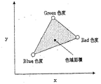
さらにまた、図6において色域面積の定義図を示す。色域面積は各RGB色度点を囲んだ面積とNTSCとの比を示す。この面積が大きいほど、色再現性が高くなり、色純度の高いパネル表示が得られる。 Further, FIG. 6 shows a definition diagram of the color gamut area. The color gamut area indicates the ratio of the area surrounding each RGB chromaticity point to NTSC. The larger this area, the higher the color reproducibility and the higher the color purity of the panel display.
なお、本発明は上記の実施形態例に限定されるものではなく、本発明の要旨を逸脱しない範囲内で種々の変更や改良等はなんら差し支えない。たとえば、上記半透過型液晶表示装置AはSTN型単純マトリックス方式であるが、この方式に代えてTFTやTFDを内設したアクティブ型の液晶表示装置でも同じ作用効果を奏する。 It should be noted that the present invention is not limited to the above-described embodiments, and various changes and improvements can be made without departing from the scope of the present invention. For example, the transflective liquid crystal display device A is of the STN type simple matrix system, but an active liquid crystal display device in which TFTs and TFDs are provided in place of this system has the same effect.
1…コモン側のガラス基板
2…光反射膜
3…着色層
4…オーバーコート層
5、10…透明電極
6、11…配向膜
7…光透過部
8…切欠部
9…セグメント側のガラス基板
12…液晶層
13、14、16…位相差板
17…偏光板
18…ブラックマトリックス
P…透明樹脂層
DESCRIPTION OF
Claims (3)
前記第1基板の前記第1主面に対向して配置された第2基板を含んでなる第2部材と、
前記第1部材と前記第2部材との間に介在する液晶層と、
前記第1基板の前記第2主面に対向して配置されたバックライトと、を備え、
前記光反射膜の一部は、前記ブラックマトリクスと前記バックライトとの間に位置しており、
前記透明樹脂層の前記光反射膜に対する被着面積は、前記複数の着色層の各々に対応させて、該複数の着色層のうちの少なくとも一つの着色層で異なるように設定されている、液晶表示装置。 A first substrate having a first main surface and a second main surface located on the opposite side of the first main surface, and light having a light transmitting portion provided on the first main surface side of the first substrate A reflective film; a transparent resin layer provided on the light reflective film; a plurality of colored layers of different colors provided on the transparent resin layer and the light transmitting portion; and a black matrix positioned between the adjacent colored layers A first member comprising:
A second member comprising a second substrate disposed to face the first main surface of the first substrate;
A liquid crystal layer interposed between the first member and the second member;
A backlight disposed opposite to the second main surface of the first substrate,
A part of the light reflecting film is located between the black matrix and the backlight,
The area where the transparent resin layer is applied to the light reflecting film is set to be different in at least one colored layer of the plurality of colored layers, corresponding to each of the plurality of colored layers. Display device.
前記ブラックマトリクスは、前記光反射膜に設けられた前記透明樹脂層上に設けられている、請求項1に記載の液晶表示装置。 The light reflecting film is provided on the first main surface side of the first substrate so as to straddle the adjacent colored layers,
The liquid crystal display device according to claim 1, wherein the black matrix is provided on the transparent resin layer provided on the light reflecting film.
前記被着面積は、前記赤色着色層に対応する部位および前記緑色着色層に対応する部位に比べて、前記青色着色層に対応する部位の方が小さい、請求項1または2に記載の液晶表示装置。 The plurality of colored layers are constituted by a red colored layer, a green colored layer, and a blue colored layer,
3. The liquid crystal display according to claim 1, wherein the deposition area is smaller in a portion corresponding to the blue colored layer than in a portion corresponding to the red colored layer and a portion corresponding to the green colored layer. apparatus.
Priority Applications (1)
| Application Number | Priority Date | Filing Date | Title |
|---|---|---|---|
| JP2007117673A JP4633083B2 (en) | 2007-04-26 | 2007-04-26 | Liquid crystal display device |
Applications Claiming Priority (1)
| Application Number | Priority Date | Filing Date | Title |
|---|---|---|---|
| JP2007117673A JP4633083B2 (en) | 2007-04-26 | 2007-04-26 | Liquid crystal display device |
Related Parent Applications (1)
| Application Number | Title | Priority Date | Filing Date |
|---|---|---|---|
| JP2002315749A Division JP2004151309A (en) | 2002-09-26 | 2002-10-30 | Transflective color liquid crystal display device |
Publications (2)
| Publication Number | Publication Date |
|---|---|
| JP2007256965A JP2007256965A (en) | 2007-10-04 |
| JP4633083B2 true JP4633083B2 (en) | 2011-02-16 |
Family
ID=38631205
Family Applications (1)
| Application Number | Title | Priority Date | Filing Date |
|---|---|---|---|
| JP2007117673A Expired - Fee Related JP4633083B2 (en) | 2007-04-26 | 2007-04-26 | Liquid crystal display device |
Country Status (1)
| Country | Link |
|---|---|
| JP (1) | JP4633083B2 (en) |
Citations (3)
| Publication number | Priority date | Publication date | Assignee | Title |
|---|---|---|---|---|
| JP2001125094A (en) * | 1999-10-28 | 2001-05-11 | Fujitsu Ltd | Liquid crystal display device |
| JP2003177410A (en) * | 2001-12-13 | 2003-06-27 | Toray Ind Inc | Color filter for liquid crystal display device and semitransmissive liquid crystal display device |
| JP2004151309A (en) * | 2002-10-30 | 2004-05-27 | Kyocera Corp | Transflective color liquid crystal display device |
-
2007
- 2007-04-26 JP JP2007117673A patent/JP4633083B2/en not_active Expired - Fee Related
Patent Citations (3)
| Publication number | Priority date | Publication date | Assignee | Title |
|---|---|---|---|---|
| JP2001125094A (en) * | 1999-10-28 | 2001-05-11 | Fujitsu Ltd | Liquid crystal display device |
| JP2003177410A (en) * | 2001-12-13 | 2003-06-27 | Toray Ind Inc | Color filter for liquid crystal display device and semitransmissive liquid crystal display device |
| JP2004151309A (en) * | 2002-10-30 | 2004-05-27 | Kyocera Corp | Transflective color liquid crystal display device |
Also Published As
| Publication number | Publication date |
|---|---|
| JP2007256965A (en) | 2007-10-04 |
Similar Documents
| Publication | Publication Date | Title |
|---|---|---|
| JP2003121830A (en) | Color-filter substrate assembly, method for manufacturing the same, electro-optical device, method for manufacturing the same, and electronic apparatus | |
| KR100582009B1 (en) | Semi-transmission type color liquid crystal device | |
| JP4633083B2 (en) | Liquid crystal display device | |
| JP3981321B2 (en) | Liquid crystal panel and liquid crystal display device including the liquid crystal panel | |
| JP4799474B2 (en) | Liquid crystal display | |
| JP2003121831A (en) | Color-filter substrate assembly, method for manufacturing the same, electro-optical device, method for manufacturing the same, and electronic apparatus | |
| JP3924518B2 (en) | Transflective color liquid crystal display device | |
| JP3931199B2 (en) | Reflective / transmissive color liquid crystal display | |
| JP3674582B2 (en) | Liquid crystal display device and electronic device | |
| JP3340073B2 (en) | Color liquid crystal display | |
| JP2004151309A (en) | Transflective color liquid crystal display device | |
| JP2003177392A (en) | Liquid crystal display device | |
| JP2004151399A (en) | Semitransmissive color liquid crystal display device | |
| JP4365498B2 (en) | Liquid crystal display | |
| JP3931201B2 (en) | Reflective / transmissive color liquid crystal display | |
| JP3631719B2 (en) | Liquid crystal display | |
| JP2004205853A (en) | Semi-transmission type color liquid crystal display | |
| JP4583072B2 (en) | Liquid crystal display | |
| JP2003207771A (en) | Liquid crystal display and its manufacturing method | |
| JP4174360B2 (en) | Liquid crystal display | |
| JP4776051B2 (en) | Liquid crystal display | |
| JP3931200B2 (en) | Reflective / transmissive color liquid crystal display | |
| JP3931198B2 (en) | Reflective / transmissive color liquid crystal display | |
| JP3931193B2 (en) | Reflective / transmissive color liquid crystal display | |
| JP2003066436A (en) | Semi-transmission type liquid crystal display device |
Legal Events
| Date | Code | Title | Description |
|---|---|---|---|
| A131 | Notification of reasons for refusal |
Free format text: JAPANESE INTERMEDIATE CODE: A131 Effective date: 20100511 |
|
| A521 | Request for written amendment filed |
Free format text: JAPANESE INTERMEDIATE CODE: A523 Effective date: 20100707 |
|
| A131 | Notification of reasons for refusal |
Free format text: JAPANESE INTERMEDIATE CODE: A131 Effective date: 20100803 |
|
| A521 | Request for written amendment filed |
Free format text: JAPANESE INTERMEDIATE CODE: A523 Effective date: 20100927 |
|
| TRDD | Decision of grant or rejection written | ||
| A01 | Written decision to grant a patent or to grant a registration (utility model) |
Free format text: JAPANESE INTERMEDIATE CODE: A01 Effective date: 20101019 |
|
| A01 | Written decision to grant a patent or to grant a registration (utility model) |
Free format text: JAPANESE INTERMEDIATE CODE: A01 |
|
| A61 | First payment of annual fees (during grant procedure) |
Free format text: JAPANESE INTERMEDIATE CODE: A61 Effective date: 20101116 |
|
| R150 | Certificate of patent or registration of utility model |
Free format text: JAPANESE INTERMEDIATE CODE: R150 |
|
| FPAY | Renewal fee payment (event date is renewal date of database) |
Free format text: PAYMENT UNTIL: 20131126 Year of fee payment: 3 |
|
| LAPS | Cancellation because of no payment of annual fees |