JP4632075B2 - Control device for vehicle generator - Google Patents
Control device for vehicle generator Download PDFInfo
- Publication number
- JP4632075B2 JP4632075B2 JP2001168570A JP2001168570A JP4632075B2 JP 4632075 B2 JP4632075 B2 JP 4632075B2 JP 2001168570 A JP2001168570 A JP 2001168570A JP 2001168570 A JP2001168570 A JP 2001168570A JP 4632075 B2 JP4632075 B2 JP 4632075B2
- Authority
- JP
- Japan
- Prior art keywords
- generator
- power
- vehicle
- power generation
- control device
- Prior art date
- Legal status (The legal status is an assumption and is not a legal conclusion. Google has not performed a legal analysis and makes no representation as to the accuracy of the status listed.)
- Expired - Lifetime
Links
Images


Classifications
-
- Y02T10/7005—
-
- Y02T10/7055—
-
- Y—GENERAL TAGGING OF NEW TECHNOLOGICAL DEVELOPMENTS; GENERAL TAGGING OF CROSS-SECTIONAL TECHNOLOGIES SPANNING OVER SEVERAL SECTIONS OF THE IPC; TECHNICAL SUBJECTS COVERED BY FORMER USPC CROSS-REFERENCE ART COLLECTIONS [XRACs] AND DIGESTS
- Y02—TECHNOLOGIES OR APPLICATIONS FOR MITIGATION OR ADAPTATION AGAINST CLIMATE CHANGE
- Y02T—CLIMATE CHANGE MITIGATION TECHNOLOGIES RELATED TO TRANSPORTATION
- Y02T10/00—Road transport of goods or passengers
- Y02T10/80—Technologies aiming to reduce greenhouse gasses emissions common to all road transportation technologies
- Y02T10/92—Energy efficient charging or discharging systems for batteries, ultracapacitors, supercapacitors or double-layer capacitors specially adapted for vehicles
Description
【0001】
【発明の属する技術分野】
本発明は、車両用発電機の制御装置に関する。蓄電手段と発電機とを搭載する自動車に適用される。
【0002】
【従来の技術】
近年、CO2 削減といった環境の面等から、車両の燃費向上が求められており、減速時に車両の運動エネルギを発電機で電気エネルギに変換して、バッテリや電気二重層コンデンサ等に蓄える回生システムが注目されている。従来の車両用の発電機は、電気負荷(ECU、ヘッドライト、ブロワ、ワイパ、AV機器、ナビゲーションシステム等で)で消費される電力を供給することが可能なように、その最大出力を1.0〜1.7kW程度に設定するのが一般的であった。しかしながら、回生システムで使用される発電機は、車両の減速エネルギを回収するためにはより大きな出力(例えば3〜10kW程度)とする必要がある。電気負荷の平均消費電力は、各負荷の使用状態にもよるが、10−15モ−ド走行時には0.2kW程度である。
【0003】
【発明が解決しようとする課題】
本出願人は、発電機の最大出力電力は、電気負荷の平時の平均消費電力に比較して格段に大きく、その差は回生制動型発電機において一層甚だしくなる。その結果、発電機はほとんどの場合において発電効率が低い小出力動作点で運転されることになり、平均電力損失が大きくなり、燃費の面で不利になるという問題があることを見いだした。
【0004】
更に具体的に説明すれば、発電機の損失は、その出力電力に無関係の固定的な損失や出力電力の変化に正相関を有する損失があり、小出力動作点では出力電力に比較して固定的な損失が大きいため、効率が低下する。
【0005】
本発明は上記問題点に鑑みなされたものであり、装置構成の複雑化を抑止しつつ小負荷時の発電効率の向上を実現可能な車両用発電機の制御装置を提供することを、その目的としている。
【0006】
【課題を解決するための手段】
請求項1記載の車両用発電機の制御装置は、車両用電気負荷に電力を供給する蓄電手段と、前記蓄電手段及び前記車両用電気負荷に電力を供給する発電機と、前記発電機の出力電力を調整する発電制御部とを備え、前記発電制御部が、前記発電機の平均出力電力が前記車両用電気負荷の消費電力と略等しくなるように前記発電機を間欠発電させる間欠発電モードを有する車両用発電機の制御装置であり、前記発電機の回転数を検出する回転数検出手段を有し、前記発電制御部が、あらかじめ記憶する前記発電機の回転数と発電効率と出力電力との関係に基づいて、現回転数における発電効率が良好な出力電力を前記発電機に間欠発電させることを特徴としている。
【0007】
本構成によれば、車両用電気負荷の消費電力が小さくても、発電機を間欠運転し、その発電停止時に蓄電手段から車両用電気負荷に給電し、その発電時に蓄電手段の充電と車両用電気負荷への給電を行うことにより、発電時の発電機の動作点を大出力電力側へシフトさせることにより、発電機の効率を向上させる。
【0008】
なお、蓄電手段を利用するため、その損失が効率低減要素となるが、発電機効率の向上が蓄電手段の損失増加分を上回る条件時に、この間欠発電モードを利用すれば総合エネルギー効率を改善することができる。
【0010】
発電機の発電効率と出力電力との間の関係は回転数に応じて変化するので、検出した回転数に応じて発電効率が良好(たとえば最高)となる出力電力で発電機を運転することにより、車両用電気負荷の消費電力や回転数変動にかかわらず常に発電機を最高又は良好な状態で発電させることができる。
【0011】
請求項2記載の構成は車両用電気負荷に電力を供給する蓄電手段と、前記蓄電手段及び前記車両用電気負荷に電力を供給する発電機と、前記発電機の出力電力を調整する発電制御部とを備え、前記発電制御部が、前記発電機の平均出力電力が前記車両用電気負荷の消費電力と略等しくなるように前記発電機を間欠発電させる間欠発電モードを有する車両用発電機の制御装置において更に、前記発電制御部が、前記車両用電気負荷の消費電力に略等しい出力電力を前記発電機に連続発電させる連続発電モードを有し、前記両モードのうちからエネルギー効率に優れる方を選択することを特徴としている。本構成によれば、間欠発電モードが連続発電モードよりエネルギー効率(総合効率)が優れる場合のみ間欠発電モードを実施するので、実現可能な最高効率で発電を行うことができる。
【0012】
請求項3記載の構成は請求項2記載の車両用発電機の制御装置において更に、前記発電制御部が、前記発電機の発電効率および前記蓄電手段の充放電効率に基づいて前記エネルギー効率を推定することを特徴としているので、蓄電手段の充放電における損失を加味したエネルギー効率を向上することができる。
【0013】
請求項4記載の構成は請求項1乃至3のいずれか記載の車両用発電機の制御装置において更に、前記発電制御部が、車両減速時に前記発電機を出力可能な最高出力電力で前記発電機を発電させ、前記車両減速でない場合に前記発電機を間欠発電させることを特徴としている。本構成によれば、回生制動を制約することなく、エネルギー効率向上を実現することができる。
【0014】
請求項5記載の構成は請求項1乃至4のいずれか記載の車両用発電機の制御装置において更に、前記発電制御部が、車両加速度が所定値を超える場合に前記発電機の発電を停止することを特徴としている。本構成によれば、大加速時に発電機を停止するので、加速性が向上する。なお、この時、蓄電手段が車両用電気負荷に給電を担当するが、発電機の発電復帰後、蓄電手段は再度充電される。
【0015】
請求項6記載の構成は請求項1乃至5のいずれか記載の車両用発電機の制御装置において更に、前記蓄電手段のSOC又は電圧を検出する手段を有し、前記間欠発電モードが、前記蓄電手段のSOC又は電圧が第一の所定値まで上昇するまで前記発電機に所定出力での発電を指令し、前記蓄電手段のSOC又は電圧が前記第一の所定値に到達した後、第二の所定値まで低下するまで前記発電機の発電を停止させる制御からなることを特徴としている。
【0016】
すなわち、本構成によれば、蓄電手段の充電状態の2つの値の間で発電機を休止させるので、間欠発電を簡単に実施することができる。また、発電停止判定に電圧を用い、発電開始判定にSOCを用いてもよく、その逆でもよい。
【0017】
請求項7記載の構成によれば請求項1乃至6のいずれか記載の車両用発電機の制御装置において更に、前記蓄電手段が、リチウム電池からなる。リチウム電池は、充放電損失が小さいので、エネルギー効率を向上することができる。
【0018】
請求項8記載の構成によれば請求項1乃至6のいずれか記載の車両用発電機の制御装置において更に、前記蓄電手段が、電気二重層コンデンサからなる。電気二重層コンデンサは、充放電損失が小さいので、エネルギー効率を向上することができる。
【0019】
【発明の実施の形態】
本発明の車両用発電機の制御装置の好適な態様を以下の実施例により詳細に説明する。
【0020】
(構成)
本発明の実施例1における回路構成を図1に示す。
【0021】
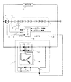
複数のリチウム電池を直列に接続してなる組電池1は、電気負荷2に電力を供給する。発電機3は電気負荷2に電力を供給するとともに組電池1を充電する。発電機3は、電機子巻線4、三相全波整流器5、界磁巻線6、界磁電流制御用スイッチ7及びフライホイルダイオードFDなどを有している。コントローラ8は発電機3を制御する。組電池1の電流を検出する電流センサ9からの信号線11、組電池1の電圧を検出する信号線12、組電池1内の温度センサ10からの信号線13が、コントローラ8に接続されている。更に、センサ部分は示していないが、車速センサからの信号線14、発電機回転数センサからの信号線15が接続されている。コントローラ8は、界磁電流制御信号線16を通じて界磁電流制御用スイッチ7を断続制御している。
【0022】
(動作)
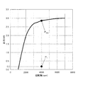
発電機3の回転数と最大出力との関係の一例を図2に示す。車両減速時にエネルギを回生する場合は、回転数に応じて最大出力に略等しい出力で発電する。しかしながら、減速時以外の場合において、発電機に要求される出力は回生時に比べ著しく小さくなる。従来は、電気負荷2で消費される分の電力をリアルタイムに発電していたため、例えば電気負荷2の消費電力が0.2kW程度で、発電機回転数が約4000rpmの場合には、発電機の動作点は図中のP1 となり、この回転数での最大出力点Pmaxに対して非常に小さい(約7%)出力で発電せざるをえなかった。
【0023】
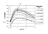
発電機3の出力と発電効率との関係の一例を図3に示す。
【0024】
4000rpmで0.2kWを出力する(点A)場合、同回転数において発電効率が最高となる1.0kW出力時(点B)に比べて、発電効率が約20%低下し、燃費向上の妨げとなっていた。
【0025】
そこでこの実施例では、発電効率が高い動作点(点B)で間欠的に発電を行い、平均発電電力が電気負荷2での消費電力と略等しくなるようにすることで、高効率な運転を可能とした。この間欠運転時における発電機出力、、Li電池の入出力電力、電気負荷の消費電力を図4に示す。時間をt(min)とすると、T1 ≦t<T2 の期間では、発電機は効率が高い1.0kWの出力で発電し、その中の0.2kWを電気負荷へ供給し、残りの0.8kWはLi電池へ充電する。次にT2 ≦t<T3 の期間では、発電機は発電を停止し、Li電池が電気負荷へ0.2kWを供給する。T3 以降も同様な動作を繰り返す。発電機が動作している時間と停止している時間の比率は、(T2 −T1 )/(T3 −T1 )=1/5となっているため、発電機は平均すると電気負荷の消費電力と略等しい電力を出力することとなる。ただし、発電機の出力が急激に変化すると、発電機トルクが急激に変化し運転者に違和感を与えるので、実際には発電機の出力を違和感を与えない程度に徐々に変化させる。
【0026】
図4のような間欠的な動作をする場合には、発電したエネルギを一旦電池に蓄えてから電気負荷へ供給するので、電池1の充放電による損失も考慮すると、より最適な運転が可能となる。発電機3で発電したエネルギを一旦電池に蓄えてから負荷2へ供給する場合には、電池1の充放電による損失のために、電気負荷の消費電力が所定値以下の場合は、間欠的な動作の方がトータルのエネルギ効率が高く、逆に所定値を上回る場合には間欠的で無くリアルタイムに負荷消費電力に応じた出力で動作する方がトータルのエネルギ効率が高くなる。
【0027】
この点について以下詳しく説明する。リアルタイムに負荷消費電力に応じた出力で動作する場合には、発電機から電気負荷へ直接電力を供給するので、電池の充放電による損失は無く、トータルのエネルギ効率E1 は、
E1 =ηG (PL ,N) 〔%〕
となる。ここで、PL は電気負荷での消費電力(W)、ηG (p,N)は発電機の発電効率であり、出力pと発電機回転数Nの関数である。ηG (p,N)の一例は図3に示したようなものである。一方で、効率が良い所定の出力Pconst で間欠的な動作をする場合は、エネルギを一旦電池に蓄えるので電池の充放電による損失が発生し、トータルのエネルギ効率E2 は、
E2 ={PL /Pconst} ・ηG (Pconst ,N)+(Pconst −PL)/Pconst・{ηG(Pconst ,N)/100}・{ηbat1(Pconst −PL )/100}・{ηbat2(PL )/100}×100〔%〕
となる。ここでηbat1(P)は充電効率(%)、ηbat2(P)は電池の放電効率(%)であり、各々の充電電力および充電電力の関数である。充電効率および放電効率は電池の内部抵抗により変化する。組電池1の内部抵抗が100mΩでの一例を図5に示す。E1 とE2 を比較して、E1 ≧E2 の場合はリアルタイムに負荷消費電力に応じた出力で動作させ、E1 <E2 の場合は間欠的な動作をさせれば最も高効率な運転が可能となる。
【0028】
組電池の内部抵抗が100mΩ、Pconst =1.0kWの条件においてE1 とE2 を比較した一例を図6に示す。電気負荷の消費電力PLが約0.8kWより小さい場合にはE1 ≧E2 となるのでリアルタイムに負荷消費電力に応じた出力で動作させ、PL が約0.8kWより小さい場合にはE1 <E2 となるので間欠的な動作をとする制御を行う。
【0029】
次に、減速エネルギを効率よく回生しながら、なお且つ上記のような発電機の高効率運転制御を行う方法について説明する。燃料を消費しながらエンジンを回転させて発電機を駆動している状態では、上記のような高効率運転制御を行うと車両のエネルギ効率は高くなる。一方で、減速時に車輪から伝達されてくるエネルギで発電機を駆動している状態では、発電機は最大出力で動作させる方が多くのエネルギを回生できるので、燃費が向上する。従って、本発明では、車速センサやブレーキペダルのストローク等から車両が減速状態であることを見出して、減速時には発電機は最大出力で発電し、発電時以外では上記のような間欠運転による高効率運転制御を行う。
【0030】
上述した制御は、コントローラ8により容易に実施できることは明白であるので、これ以上の説明は省略する。
【0031】
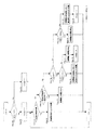
減速時以外で間欠運転による高効率運転制御を行う場合には、電池の充電状態(SOC:State of Charge)および、車両の加速度に基づいて発電機のON/OFFを制御することができる。具体的な制御方法を、図7を用いて説明する。Step01において電池のSOCを第一の所定値(SOC- 1)と比較し、小さい場合にはChargeフラグを1にセットし(Step02)、それ以外の場合にはChargeフラグを0にセット(Step03)する。
【0032】
次に、Step04において車両が減速状態であるかどうか判断し、減速状態の場合にはStep05で発電機は最大出力で発電する。減速状態でない場合には、Step06で車両の加速度が所定値(acc〔m/s2 〕)以上であるか判定し、所定値以上の場合はStep07で発電を停止し、それ以外の場合にはStep08でChargeフラグが1かどうか判定する。Chargeフラグが1の場合には更にStep09で電池のSOCを第一の所定値(SOC- 1)と比較し、小さい場合にはStep10において、発電機は回転数に応じて高効率となる出力で発電を行い、それ以外の場合にはStep11で発電を停止し、Step12でChargeフラグを0にセットする。また、Step08で、Chargeフラグが1かどうか判定し、1でない場合にはStep13で電池のSOCを第二の所定値(SOC- 2)と比較し、大きい場合にはStep14で発電を停止し、それ以外の場合にはStep15で、発電機は回転数に応じて高効率となる出力で発電を行い、Step16でChargeフラグを1にセットする。ここで、第一の所定値(SOC- 1)は第二の所定値(SOC- 2)よりも大きくなるように設定してあり、例えば、SOC- 1=60%、SOC- 2=50%というように設定する。また、加速状態を判定する所定値(acc)は、例えばacc=0.5〔m/s2 〕に設定する。
【0033】
この制御を行った場合における、車速、加速度、電池のSOC、発電機の出力の時間変化の一例を図8に示す。時間をtとし、Chargeフラグはt=T1 において1であるとして詳細を説明する。
【0034】
T1 ≦t<T2 の期間では、車速は40km/h一定で、加速度は0〔m/s2 〕、Chargeフラグが1で、SOCは第一の所定値(SOC- 1=60%)よりも小さいので、図7のStep10により発電機は回転数に応じて高効率となる出力(1.0kW)で発電を行う。電気負荷の消費電力は約0.2kWであるので、発電した1.0kW中の0.2kWは電気負荷へ供給され、残りの0.8kWはLi電池に充電され、SOCが増加する。
【0035】
T2 ≦t<T3 の期間では、車両は40km/hから80km/hに加速中で、加速度は0.56〔m/s2 〕であり所定の加速度(acc=0.5〔m/s2 〕)以上であるので、Step07により発電機は発電を停止する。Li電池から電気負荷へ0.2kWが供給され、SOCが減少する。
【0036】
T2 ≦t<T4 の期間では、車両は80km/h一定で、加速度は0〔m/s2 〕、Chargeフラグが1で、SOCは第一の所定値(SOC- 1=60%)よりも小さいので、Step10により発電機は回転数に応じて高効率となる出力(1.0kW)で発電を行う。発電した1.0kW中の0.2kWは電気負荷へ供給され、残りの0.8kWはLi電池に充電され、SOCが増加する。
【0037】
t=T4 において、SOCは第一の所定値(SOC- 1=60%)に到達し、Step11により発電機は発電を停止し、Step12によりChargeフラグを0にセットする。
【0038】
T4 <t<T5の期間では、車両は80km/h一定で、加速度は0〔m/s2 〕、Chargeフラグが0で、SOCは第二の所定値(SOC- 2=50%)よりも大きいので、Step14により発電機は発電を停止する。Li電池から電気負荷へ0.2kWが供給され、SOCが減少する。
【0039】
t=T5 において、SOCは第二の所定値(SOC- 2=50%)に到達し、Step15により発電機は発電を停止し、Step16によりChargeフラグを1にセットする。
【0040】
同様に、T5 <t<T9 の期間では、SOCが増加して第一の所定値(SOC- 1=60%)に到達したら発電を停止し、次にSOCが減少して第二の所定値(SOC- 2=50%)に到達したら発電を再開するという運転を繰り返す。
【0041】
T9 <t<T10の期間では、車両は80km/hから0km/hに減速中であり、Step05により発電機は回転数に応じた最大出力で発電する。発電した電力中の0.2kWは電気負荷へ供給され、残りはLi電池に充電されSOCは増加する。
【0042】
T10<t<T11の期間では、車両は0km/hで停車しており、加速度は0〔m/s2 〕、Chargeフラグが0で、SOCは第二の所定値(SOC- 2=50%)よりも大きいので、Step14により発電機は発電を停止する。
【0043】
T11<t<T12の期間では、車両は40km/hから70km/hに加速中で、加速度は0.97〔m/s2 〕であり所定の加速度(acc=0.5〔m/s2 〕)以上であるので、Step07により発電機は発電を停止する。
【0044】
t=T12において、SOCは第一の所定値(SOC- 1=60%)に到達し、Step11により発電機は発電を停止し、Step12によりChargeフラグを0にセットする。
【0045】
T12<t<T13の期間では、車両は80km/h一定で、加速度は0〔m/s2 〕、Chargeフラグが0で、SOCは第二の所定値(SOC- 2=50%)よりも大きいので、Step14により発電機は発電を停止する。
【0046】
なお、上記制御では電池のSOCに基づいて発電機のON/OFFを制御したが、電池の電圧に基づいて、電圧が第一の所定値(例えば39.0V)に到達したら発電を停止し、次にSOCが第二の所定値(例えば35.0V)に到達したら発電を再開するような制御を行っても良い。
【0047】
(効果)
(1)電気負荷の消費電力が小さい場合においても、高効率な発電が可能であり、燃費を向上することができる。
(2)充放電の効率が高いLi電池や電気二重層コンデンサを使用することで、エネルギ損失が小さくなり、燃費が向上する。
(3)Li電池や電気二重層コンデンサへの充放電による損失も考慮して、電気負荷の消費電力に応じてエネルギ効率が最大となるように発電機の運転方法を最適化しているので、高効率運転制御をより効果的に行うことができる。
(4)電池のSOC又は電圧に基づいた発電機のON/OFF制御を行うことで、回生したエネルギを使い切ってから発電機が発電を開始する(減速時は除く)ので、無駄に発電しなくなり燃費が向上する。
【図面の簡単な説明】
【図1】本発明の車両用発電機の制御装置の一実施例を示す回路図である。
【図2】発電機の回転数と最大出力との関係を示す特性図である。
【図3】発電機の出力と発電効率との関係を示す特性図である。
【図4】各部電力の時間変化を示すタイミングチャートである。
【図5】電池の充放電電力と効率との関係を示す特性図である。
【図6】電気負荷の消費電力とトータルのエネルギー効率との関係を示す特性図である。
【図7】発電制御動作を示すフローチャートである。
【図8】図7に示す制御動作を行う場合の車速、加速度、電池のSOC、発電機の出力の時間変化を示すタイミングチャートである。
【符号の説明】
1 組電池(蓄電手段)
2 車両用電気負荷
3 発電機
8 コントローラ(発電制御部)
15 回転数検出器[0001]
BACKGROUND OF THE INVENTION
The present invention relates to a control device for a vehicular generator. It is applied to an automobile equipped with a power storage means and a generator.
[0002]
[Prior art]
In recent years, there has been a demand for improved fuel efficiency of vehicles due to environmental aspects such as CO2 reduction, and a regenerative system that converts vehicle kinetic energy into electrical energy with a generator during deceleration and stores it in a battery, an electric double layer capacitor, or the like. Attention has been paid. A conventional generator for a vehicle has a maximum output of 1. to be able to supply electric power consumed by an electric load (ECU, headlight, blower, wiper, AV equipment, navigation system, etc.). Generally, it was set to about 0 to 1.7 kW. However, the generator used in the regeneration system needs to have a larger output (for example, about 3 to 10 kW) in order to recover the deceleration energy of the vehicle. The average power consumption of the electric load is about 0.2 kW when traveling in the 10-15 mode, although it depends on the usage state of each load.
[0003]
[Problems to be solved by the invention]
The present applicant has found that the maximum output power of the generator is much larger than the average power consumption during normal times of the electric load, and the difference becomes even more severe in the regenerative braking generator. As a result, it was found that the generator is operated at a small output operating point where the generation efficiency is low in most cases, resulting in a problem that the average power loss becomes large and the fuel consumption becomes disadvantageous.
[0004]
More specifically, the loss of the generator includes a fixed loss irrelevant to the output power and a loss having a positive correlation with the change in the output power, and is fixed compared to the output power at the small output operating point. The efficiency is reduced due to the large loss.
[0005]
The present invention has been made in view of the above problems, and an object of the present invention is to provide a control device for a vehicular generator capable of improving the power generation efficiency at a small load while suppressing the complexity of the device configuration. It is said.
[0006]
[Means for Solving the Problems]
The control device for a vehicular generator according to
[0007]
According to this configuration, even if the power consumption of the electric load for the vehicle is small, the generator is intermittently operated, the electric power is supplied from the electric storage means to the electric load for the vehicle when the electric power generation is stopped, and the electric storage means is charged and charged for the electric power generation. By supplying power to the electric load, the operating point of the generator during power generation is shifted to the large output power side, thereby improving the efficiency of the generator.
[0008]
In addition, since the loss becomes an efficiency reduction factor because the power storage means is used, the total energy efficiency can be improved if this intermittent power generation mode is used when the improvement of the generator efficiency exceeds the loss increase of the power storage means. be able to.
[0010]
Since the relationship between the power generation efficiency of the generator and the output power changes according to the rotational speed, by operating the generator with the output power at which the power generation efficiency is good (for example, the highest) according to the detected rotational speed Regardless of the power consumption of the electric load for the vehicle or fluctuations in the rotational speed, the generator can always generate power in the highest or good state.
[0011]
3. The configuration according to
[0012]
Structure of
[0013]
According to a fourth aspect of the present invention, in the vehicle generator control device according to any one of the first to third aspects, the power generation control unit is configured to output the power generator at a maximum output power that can output the power generator when the vehicle decelerates. Is generated, and the generator is intermittently generated when the vehicle is not decelerated. According to this configuration, energy efficiency can be improved without restricting regenerative braking.
[0014]
According to a fifth aspect of the present invention, in the vehicle generator control device according to any one of the first to fourth aspects, the power generation control unit further stops the power generation of the generator when the vehicle acceleration exceeds a predetermined value. It is characterized by that. According to this configuration, since the generator is stopped at the time of large acceleration, the acceleration performance is improved. At this time, the power storage means takes charge of power supply to the electric load for the vehicle, but after the power generation of the generator is restored, the power storage means is charged again.
[0015]
According to a sixth aspect of the present invention, the vehicle generator control device according to any one of the first to fifth aspects further includes means for detecting an SOC or a voltage of the power storage means, wherein the intermittent power generation mode is the power storage mode. Command the generator to generate power at a predetermined output until the SOC or voltage of the means rises to a first predetermined value, and after the SOC or voltage of the power storage means reaches the first predetermined value, It is characterized by comprising control for stopping the power generation of the generator until it drops to a predetermined value.
[0016]
That is, according to this configuration, the generator is suspended between the two values of the charging state of the power storage means, so that intermittent power generation can be easily performed. Moreover, a voltage may be used for power generation stop determination, and SOC may be used for power generation start determination, or vice versa.
[0017]
According to a seventh aspect of the present invention, in the vehicle generator control device according to any one of the first to sixth aspects, the power storage means comprises a lithium battery. Since the lithium battery has a small charge / discharge loss, energy efficiency can be improved.
[0018]
According to the eighth aspect of the present invention, in the vehicle generator control device according to any one of the first to sixth aspects, the power storage means comprises an electric double layer capacitor. Since the electric double layer capacitor has a small charge / discharge loss, the energy efficiency can be improved.
[0019]
DETAILED DESCRIPTION OF THE INVENTION
The preferred embodiments of the control device for a vehicle generator according to the present invention will be described in detail with reference to the following examples.
[0020]
(Constitution)
FIG. 1 shows a circuit configuration in
[0021]
An assembled
[0022]
(Operation)
An example of the relationship between the rotational speed of the
[0023]
An example of the relationship between the output of the
[0024]
When 0.2 kW is output at 4000 rpm (point A), the power generation efficiency is reduced by about 20% compared to the 1.0 kW output (point B) at which the power generation efficiency reaches the maximum at the same rotation speed, which hinders improvement in fuel consumption. It was.
[0025]
Therefore, in this embodiment, high-efficiency operation is achieved by intermittently generating power at an operating point (point B) with high power generation efficiency so that the average generated power is substantially equal to the power consumed by the
[0026]
When the intermittent operation as shown in FIG. 4 is performed, the generated energy is temporarily stored in the battery and then supplied to the electric load. Therefore, when the loss due to charging / discharging of the
[0027]
This point will be described in detail below. When operating at an output corresponding to the load power consumption in real time, power is directly supplied from the generator to the electric load, so there is no loss due to charging / discharging of the battery, and the total energy efficiency E1 is
E1 = ηG (PL, N) [%]
It becomes. Here, PL is the power consumption (W) at the electric load, η G (p, N) is the power generation efficiency of the generator, and is a function of the output p and the generator speed N. An example of ηG (p, N) is as shown in FIG. On the other hand, when intermittent operation is performed at a predetermined output Pconst with high efficiency, energy is temporarily stored in the battery, so that loss due to charging / discharging of the battery occurs, and the total energy efficiency E2 is
E2 = {PL / Pconst} .eta.G (Pconst, N) + (Pconst-PL) / Pconst. {. Eta.G (Pconst, N) / 100}. {. Eta.bat1 (Pconst-PL) / 100}. {. Eta.bat2 (PL). / 100} × 100 [%]
It becomes. Here, ηbat1 (P) is the charging efficiency (%), ηbat2 (P) is the discharging efficiency (%) of the battery, and is a function of each charging power and charging power. Charging efficiency and discharging efficiency vary depending on the internal resistance of the battery. An example in which the internal resistance of the assembled
[0028]
FIG. 6 shows an example in which E1 and E2 are compared under the condition that the internal resistance of the assembled battery is 100 mΩ and Pconst = 1.0 kW. When the electric power consumption PL of the electric load is smaller than about 0.8 kW, E1 ≧ E2 is established, so that the output is operated in real time according to the load electric power consumption. When PL is smaller than about 0.8 kW, E1 <E2 Therefore, the control to perform intermittent operation is performed.
[0029]
Next, a method for performing high-efficiency operation control of the generator as described above while efficiently regenerating deceleration energy will be described. In a state where the generator is driven by rotating the engine while consuming fuel, the energy efficiency of the vehicle is increased by performing the high-efficiency operation control as described above. On the other hand, in a state where the generator is driven by the energy transmitted from the wheels during deceleration, the generator can regenerate more energy when operated at the maximum output, and thus fuel efficiency is improved. Therefore, in the present invention, it is found from the vehicle speed sensor, the stroke of the brake pedal, etc. that the vehicle is in a decelerating state, and the generator generates power at the maximum output when decelerating. Perform operation control.
[0030]
Since it is obvious that the control described above can be easily performed by the
[0031]
When high-efficiency operation control by intermittent operation is performed at times other than during deceleration, ON / OFF of the generator can be controlled based on the state of charge (SOC) of the battery and the acceleration of the vehicle. A specific control method will be described with reference to FIG. In
[0032]
Next, in
[0033]
FIG. 8 shows an example of changes over time in vehicle speed, acceleration, battery SOC, and generator output when this control is performed. The details will be described assuming that the time is t and the Charge flag is 1 at t = T1.
[0034]
In the period of T1 ≦ t <T2, the vehicle speed is constant at 40 km / h, the acceleration is 0 [m / s2], the Charge flag is 1, and the SOC is smaller than the first predetermined value (SOC-1 = 60%). Therefore, at
[0035]
In the period of T2 ≦ t <T3, the vehicle is accelerating from 40 km / h to 80 km / h, the acceleration is 0.56 [m / s2], and a predetermined acceleration (acc = 0.5 [m / s2]) Since it is above, a generator stops an electric power generation by Step07. 0.2 kW is supplied from the Li battery to the electric load, and the SOC decreases.
[0036]
In the period of T2 ≦ t <T4, the vehicle is constant at 80 km / h, the acceleration is 0 [m / s2], the Charge flag is 1, and the SOC is smaller than the first predetermined value (SOC-1 = 60%). Therefore, at
[0037]
At t = T4, the SOC reaches a first predetermined value (SOC-1 = 60%), the generator stops generating power in
[0038]
In the period of T4 <t <T5, the vehicle is constant at 80 km / h, the acceleration is 0 [m / s2], the Charge flag is 0, and the SOC is larger than the second predetermined value (SOC-2 = 50%). Therefore, the generator stops power generation in
[0039]
At t = T5, the SOC reaches a second predetermined value (SOC-2 = 50%), the generator stops generating power at
[0040]
Similarly, during the period of T5 <t <T9, when the SOC increases and reaches the first predetermined value (SOC-1 = 60%), the power generation is stopped, and then the SOC decreases and the second predetermined value is reached. When (SOC-2 = 50%) is reached, the operation of restarting power generation is repeated.
[0041]
In the period of T9 <t <T10, the vehicle is decelerating from 80 km / h to 0 km / h, and in
[0042]
In the period of T10 <t <T11, the vehicle is stopped at 0 km / h, the acceleration is 0 [m / s2], the Charge flag is 0, and the SOC is a second predetermined value (SOC-2 = 50%). Therefore, the generator stops generating power at
[0043]
In the period of T11 <t <T12, the vehicle is accelerating from 40 km / h to 70 km / h, the acceleration is 0.97 [m / s2], and a predetermined acceleration (acc = 0.5 [m / s2]) Since it is above, a generator stops an electric power generation by Step07.
[0044]
At t = T12, the SOC reaches a first predetermined value (SOC-1 = 60%), the generator stops generating power in
[0045]
In the period of T12 <t <T13, the vehicle is constant at 80 km / h, the acceleration is 0 [m / s 2], the Charge flag is 0, and the SOC is larger than the second predetermined value (SOC-2 = 50%). Therefore, the generator stops power generation in
[0046]
In the above control, ON / OFF of the generator is controlled based on the SOC of the battery. When the voltage reaches a first predetermined value (for example, 39.0 V), the power generation is stopped based on the battery voltage. Next, control may be performed so that power generation is resumed when the SOC reaches a second predetermined value (for example, 35.0 V).
[0047]
(effect)
(1) Even when the power consumption of the electrical load is small, highly efficient power generation is possible, and fuel consumption can be improved.
(2) By using a Li battery or an electric double layer capacitor having high charge / discharge efficiency, energy loss is reduced and fuel efficiency is improved.
(3) Considering losses due to charging / discharging of Li batteries and electric double layer capacitors, the generator operation method is optimized so that the energy efficiency is maximized according to the power consumption of the electric load. Efficient operation control can be performed more effectively.
(4) By performing ON / OFF control of the generator based on the SOC or voltage of the battery, the generator starts generating power after the regenerated energy is used up (except during deceleration), so power generation is not wasted. Fuel consumption is improved.
[Brief description of the drawings]
FIG. 1 is a circuit diagram showing an embodiment of a control device for a vehicle generator according to the present invention.
FIG. 2 is a characteristic diagram showing the relationship between the rotational speed of the generator and the maximum output.
FIG. 3 is a characteristic diagram showing the relationship between the output of the generator and the power generation efficiency.
FIG. 4 is a timing chart showing changes in power of each part over time.
FIG. 5 is a characteristic diagram showing a relationship between charge / discharge power and efficiency of a battery.
FIG. 6 is a characteristic diagram showing a relationship between power consumption of an electrical load and total energy efficiency.
FIG. 7 is a flowchart showing a power generation control operation.
8 is a timing chart showing temporal changes in vehicle speed, acceleration, battery SOC, and generator output when the control operation shown in FIG. 7 is performed.
[Explanation of symbols]
1 assembled battery (electric storage means)
2 Electric load for
15 Speed detector
Claims (8)
前記蓄電手段及び前記車両用電気負荷に電力を供給する発電機と、
前記発電機の出力電力を調整する発電制御部と、を備え、
前記発電制御部は、前記発電機の平均出力電力が前記車両用電気負荷の消費電力と略等しくなるように前記発電機を間欠発電させる間欠発電モードを有する車両用発電機の制御装置において、
前記発電機の回転数を検出する回転数検出手段を有し、前記発電制御部は、あらかじめ記憶する前記発電機の回転数と発電効率と出力電力との関係に基づいて、現回転数における発電効率が良好な出力電力を前記発電機に間欠発電させることを特徴とする車両用発電機の制御装置。 Power storage means for supplying power to the vehicle electrical load;
A generator for supplying electric power to the power storage means and the electric load for the vehicle;
A power generation control unit for adjusting the output power of the generator,
The power generation control unit, the control unit of the car dual generator that having a discontinuous generating mode the average output power of the generator to intermittently power the generator to be substantially equal to the power consumption of the vehicle electric load ,
The power generation control unit includes a rotational speed detection means for detecting the rotational speed of the generator, and the power generation control unit generates power at the current rotational speed based on a relationship among the rotational speed of the generator, power generation efficiency, and output power stored in advance. A control device for a vehicular generator, wherein output power having good efficiency is intermittently generated by the generator.
前記蓄電手段及び前記車両用電気負荷に電力を供給する発電機と、
前記発電機の出力電力を調整する発電制御部と、を備え、
前記発電制御部は、前記発電機の平均出力電力が前記車両用電気負荷の消費電力と略等しくなるように前記発電機を間欠発電させる間欠発電モードを有する車両用発電機の制御装置において、
前記発電制御部は、前記車両用電気負荷の消費電力に略等しい出力電力を前記発電機に連続発電させる連続発電モードを有し、前記両モードのうちからエネルギー効率に優れる方を選択することを特徴とする車両用発電機の制御装置。 Power storage means for supplying power to the vehicle electrical load;
A generator for supplying electric power to the power storage means and the electric load for the vehicle;
A power generation control unit for adjusting the output power of the generator,
In the vehicle generator control device having an intermittent power generation mode in which the generator intermittently generates power so that the average output power of the generator is substantially equal to the power consumption of the vehicle electrical load ,
The power generation control unit has a continuous power generation mode in which the generator continuously generates output power substantially equal to the power consumption of the vehicular electrical load, and selects one of the two modes that is more energy efficient. A control device for a vehicular generator.
前記発電制御部は、前記発電機の発電効率および前記蓄電手段の充放電効率に基づいて前記エネルギー効率を推定することを特徴とする車両用発電機の制御装置。The control device for a vehicle generator according to claim 2 ,
The power generation control unit estimates the energy efficiency based on the power generation efficiency of the power generator and the charge / discharge efficiency of the power storage means.
前記発電制御部は、車両減速時に前記発電機を出力可能な最高出力電力で前記発電機を発電させ、前記車両減速でない場合に前記発電機を間欠発電させることを特徴とする車両用発電機の制御装置。In the control apparatus of the generator for vehicles according to any one of claims 1 to 3 ,
The power generation control unit causes the generator to generate electric power with the maximum output power that can output the generator during vehicle deceleration, and intermittently generates the generator when the vehicle is not decelerated. Control device.
前記発電制御部は、車両加速度が所定値を超える場合に前記発電機の発電を停止することを特徴とする車両用発電機の制御装置。In the vehicular generator control device according to any one of claims 1 to 4 ,
The power generator control unit stops the power generation of the generator when the vehicle acceleration exceeds a predetermined value.
前記蓄電手段のSOC又は電圧を検出する手段を有し、前記間欠発電モードは、前記蓄電手段の前記SOC又は電圧が第一の所定値まで上昇するまで前記発電機に所定出力での発電を指令し、前記蓄電手段の前記SOC又は電圧が前記第一の所定値に到達した後、第二の所定値まで低下するまで前記発電機の発電を停止させる制御からなることを特徴とする車両用発電機の制御装置。In the control device of the generator for vehicles according to any one of claims 1 to 5 ,
In the intermittent power generation mode, the generator is instructed to generate power at a predetermined output until the SOC or voltage of the power storage means rises to a first predetermined value. And power generation for the vehicle, wherein the power generation of the generator is stopped until the SOC or voltage of the power storage means reaches the first predetermined value and then decreases to the second predetermined value. Machine control device.
前記蓄電手段は、リチウム電池からなることを特徴とする車両用発電機の制御装置。The vehicle generator control device according to any one of claims 1 to 6 ,
The control device for a vehicular generator, wherein the power storage means comprises a lithium battery.
前記蓄電手段は、電気二重層コンデンサからなることを特徴とする車両用発電機の制御装置。The vehicle generator control device according to any one of claims 1 to 6 ,
The control device for a vehicular generator, wherein the power storage means comprises an electric double layer capacitor.
Priority Applications (3)
| Application Number | Priority Date | Filing Date | Title |
|---|---|---|---|
| JP2001168570A JP4632075B2 (en) | 2001-06-04 | 2001-06-04 | Control device for vehicle generator |
| US10/135,699 US6583602B2 (en) | 2001-05-11 | 2002-05-01 | Vehicular power supply apparatus and method of controlling the same |
| DE10220939A DE10220939A1 (en) | 2001-05-11 | 2002-05-10 | Vehicle power supply device and method for controlling the same |
Applications Claiming Priority (1)
| Application Number | Priority Date | Filing Date | Title |
|---|---|---|---|
| JP2001168570A JP4632075B2 (en) | 2001-06-04 | 2001-06-04 | Control device for vehicle generator |
Publications (2)
| Publication Number | Publication Date |
|---|---|
| JP2002369592A JP2002369592A (en) | 2002-12-20 |
| JP4632075B2 true JP4632075B2 (en) | 2011-02-16 |
Family
ID=19010781
Family Applications (1)
| Application Number | Title | Priority Date | Filing Date |
|---|---|---|---|
| JP2001168570A Expired - Lifetime JP4632075B2 (en) | 2001-05-11 | 2001-06-04 | Control device for vehicle generator |
Country Status (1)
| Country | Link |
|---|---|
| JP (1) | JP4632075B2 (en) |
Families Citing this family (4)
| Publication number | Priority date | Publication date | Assignee | Title |
|---|---|---|---|---|
| JP4570127B2 (en) * | 2004-03-31 | 2010-10-27 | 大阪瓦斯株式会社 | Heat pump equipment |
| DE102004055128A1 (en) * | 2004-11-16 | 2006-06-01 | Volkswagen Ag | Method for controlling an operation of a hybrid motor vehicle and hybrid vehicle |
| JP5194834B2 (en) * | 2008-01-24 | 2013-05-08 | 日産自動車株式会社 | VEHICLE ELECTRIC SYSTEM CONTROL DEVICE AND CONTROL METHOD |
| JP4849421B2 (en) * | 2008-09-26 | 2012-01-11 | 三菱電機株式会社 | Generator motor control device and vehicle system including the same |
Citations (1)
| Publication number | Priority date | Publication date | Assignee | Title |
|---|---|---|---|---|
| JPH07212986A (en) * | 1994-01-19 | 1995-08-11 | Mitsubishi Electric Corp | Generation control equipment for vehicle |
-
2001
- 2001-06-04 JP JP2001168570A patent/JP4632075B2/en not_active Expired - Lifetime
Patent Citations (1)
| Publication number | Priority date | Publication date | Assignee | Title |
|---|---|---|---|---|
| JPH07212986A (en) * | 1994-01-19 | 1995-08-11 | Mitsubishi Electric Corp | Generation control equipment for vehicle |
Also Published As
| Publication number | Publication date |
|---|---|
| JP2002369592A (en) | 2002-12-20 |
Similar Documents
| Publication | Publication Date | Title |
|---|---|---|
| US7015676B2 (en) | Battery control apparatus | |
| US6318487B2 (en) | Regeneration control device of hybrid electric vehicle | |
| JP5029331B2 (en) | Vehicle power supply | |
| JP3582479B2 (en) | Vehicle battery charge control device | |
| US20090315518A1 (en) | Power supply device and vehicle | |
| US20140097676A1 (en) | Electrically powered vehicle and method for controlling electrically powered vehicle | |
| JP3180304B2 (en) | Power circuit of hybrid car | |
| JP2002325311A (en) | Vehicle equipped with super-capacitor for recovery of energy in braking | |
| JP3901235B2 (en) | Hybrid type vehicle | |
| KR102078123B1 (en) | Method for managing an alternator combined with at least one power battery and driven by a heat engine | |
| JP3465293B2 (en) | Vehicle power control device | |
| CN103326648B (en) | Power generation control | |
| JPH10295045A (en) | Control apparatus for power generation of hybrid electric vehicle | |
| US20120316719A1 (en) | Method for Controlling the State of Charge of an Electrical Energy Store | |
| JP2006312352A (en) | Control device for driving system | |
| JP2014047709A (en) | Vehicle power source device and control method for the same | |
| US9193278B2 (en) | Vehicle and method of controlling vehicle | |
| JP4010257B2 (en) | Electric vehicle and control method thereof | |
| JPH07236203A (en) | Controller for electric automobile | |
| JP3013764B2 (en) | Charge and discharge control device for hybrid electric vehicles | |
| JP5915390B2 (en) | Vehicle power supply control method and apparatus | |
| JP3651448B2 (en) | Regenerative device control device | |
| JP4632075B2 (en) | Control device for vehicle generator | |
| US9162670B2 (en) | Vehicle and method of controlling vehicle | |
| JPH07131905A (en) | Hybrid power source for electric vehicle |
Legal Events
| Date | Code | Title | Description |
|---|---|---|---|
| A621 | Written request for application examination |
Free format text: JAPANESE INTERMEDIATE CODE: A621 Effective date: 20070905 |
|
| A977 | Report on retrieval |
Free format text: JAPANESE INTERMEDIATE CODE: A971007 Effective date: 20100518 |
|
| A131 | Notification of reasons for refusal |
Free format text: JAPANESE INTERMEDIATE CODE: A131 Effective date: 20100520 |
|
| A521 | Request for written amendment filed |
Free format text: JAPANESE INTERMEDIATE CODE: A523 Effective date: 20100713 |
|
| TRDD | Decision of grant or rejection written | ||
| A01 | Written decision to grant a patent or to grant a registration (utility model) |
Free format text: JAPANESE INTERMEDIATE CODE: A01 Effective date: 20101021 |
|
| A01 | Written decision to grant a patent or to grant a registration (utility model) |
Free format text: JAPANESE INTERMEDIATE CODE: A01 |
|
| A61 | First payment of annual fees (during grant procedure) |
Free format text: JAPANESE INTERMEDIATE CODE: A61 Effective date: 20101103 |
|
| R151 | Written notification of patent or utility model registration |
Ref document number: 4632075 Country of ref document: JP Free format text: JAPANESE INTERMEDIATE CODE: R151 |
|
| FPAY | Renewal fee payment (event date is renewal date of database) |
Free format text: PAYMENT UNTIL: 20131126 Year of fee payment: 3 |
|
| R250 | Receipt of annual fees |
Free format text: JAPANESE INTERMEDIATE CODE: R250 |
|
| R250 | Receipt of annual fees |
Free format text: JAPANESE INTERMEDIATE CODE: R250 |
|
| R250 | Receipt of annual fees |
Free format text: JAPANESE INTERMEDIATE CODE: R250 |
|
| R250 | Receipt of annual fees |
Free format text: JAPANESE INTERMEDIATE CODE: R250 |
|
| R250 | Receipt of annual fees |
Free format text: JAPANESE INTERMEDIATE CODE: R250 |
|
| R250 | Receipt of annual fees |
Free format text: JAPANESE INTERMEDIATE CODE: R250 |
|
| R250 | Receipt of annual fees |
Free format text: JAPANESE INTERMEDIATE CODE: R250 |
|
| EXPY | Cancellation because of completion of term |