JP4630413B2 - Distance measuring machine and light receiving unit adjusting method of distance measuring machine - Google Patents
Distance measuring machine and light receiving unit adjusting method of distance measuring machine Download PDFInfo
- Publication number
- JP4630413B2 JP4630413B2 JP34726699A JP34726699A JP4630413B2 JP 4630413 B2 JP4630413 B2 JP 4630413B2 JP 34726699 A JP34726699 A JP 34726699A JP 34726699 A JP34726699 A JP 34726699A JP 4630413 B2 JP4630413 B2 JP 4630413B2
- Authority
- JP
- Japan
- Prior art keywords
- light
- distance measuring
- light receiving
- adjustment
- light emitting
- Prior art date
- Legal status (The legal status is an assumption and is not a legal conclusion. Google has not performed a legal analysis and makes no representation as to the accuracy of the status listed.)
- Expired - Fee Related
Links
Images


Classifications
-
- G—PHYSICS
- G01—MEASURING; TESTING
- G01S—RADIO DIRECTION-FINDING; RADIO NAVIGATION; DETERMINING DISTANCE OR VELOCITY BY USE OF RADIO WAVES; LOCATING OR PRESENCE-DETECTING BY USE OF THE REFLECTION OR RERADIATION OF RADIO WAVES; ANALOGOUS ARRANGEMENTS USING OTHER WAVES
- G01S17/00—Systems using the reflection or reradiation of electromagnetic waves other than radio waves, e.g. lidar systems
- G01S17/02—Systems using the reflection of electromagnetic waves other than radio waves
- G01S17/06—Systems determining position data of a target
- G01S17/08—Systems determining position data of a target for measuring distance only
-
- G—PHYSICS
- G01—MEASURING; TESTING
- G01C—MEASURING DISTANCES, LEVELS OR BEARINGS; SURVEYING; NAVIGATION; GYROSCOPIC INSTRUMENTS; PHOTOGRAMMETRY OR VIDEOGRAMMETRY
- G01C3/00—Measuring distances in line of sight; Optical rangefinders
- G01C3/02—Details
- G01C3/06—Use of electric means to obtain final indication
- G01C3/08—Use of electric radiation detectors
-
- G—PHYSICS
- G01—MEASURING; TESTING
- G01S—RADIO DIRECTION-FINDING; RADIO NAVIGATION; DETERMINING DISTANCE OR VELOCITY BY USE OF RADIO WAVES; LOCATING OR PRESENCE-DETECTING BY USE OF THE REFLECTION OR RERADIATION OF RADIO WAVES; ANALOGOUS ARRANGEMENTS USING OTHER WAVES
- G01S7/00—Details of systems according to groups G01S13/00, G01S15/00, G01S17/00
- G01S7/48—Details of systems according to groups G01S13/00, G01S15/00, G01S17/00 of systems according to group G01S17/00
- G01S7/491—Details of non-pulse systems
- G01S7/4911—Transmitters
-
- G—PHYSICS
- G01—MEASURING; TESTING
- G01S—RADIO DIRECTION-FINDING; RADIO NAVIGATION; DETERMINING DISTANCE OR VELOCITY BY USE OF RADIO WAVES; LOCATING OR PRESENCE-DETECTING BY USE OF THE REFLECTION OR RERADIATION OF RADIO WAVES; ANALOGOUS ARRANGEMENTS USING OTHER WAVES
- G01S7/00—Details of systems according to groups G01S13/00, G01S15/00, G01S17/00
- G01S7/48—Details of systems according to groups G01S13/00, G01S15/00, G01S17/00 of systems according to group G01S17/00
- G01S7/491—Details of non-pulse systems
- G01S7/4912—Receivers
- G01S7/4913—Circuits for detection, sampling, integration or read-out
-
- G—PHYSICS
- G01—MEASURING; TESTING
- G01S—RADIO DIRECTION-FINDING; RADIO NAVIGATION; DETERMINING DISTANCE OR VELOCITY BY USE OF RADIO WAVES; LOCATING OR PRESENCE-DETECTING BY USE OF THE REFLECTION OR RERADIATION OF RADIO WAVES; ANALOGOUS ARRANGEMENTS USING OTHER WAVES
- G01S7/00—Details of systems according to groups G01S13/00, G01S15/00, G01S17/00
- G01S7/48—Details of systems according to groups G01S13/00, G01S15/00, G01S17/00 of systems according to group G01S17/00
- G01S7/491—Details of non-pulse systems
- G01S7/4912—Receivers
- G01S7/4918—Controlling received signal intensity, gain or exposure of sensor
Description
【0001】
【発明の属する技術分野】
本発明は測距部の受光部感度を簡便に調整可能とした距離測定機及び距離測定機の受光部調整方法に関するものである。
【0002】
【従来の技術】
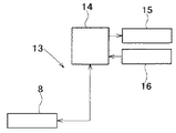
光波による距離測定は、変調した測定光を用い、反射光の位相差から距離を求めている。図4は距離測定機の基本的な測距部1の説明図であり、図5は距離測定機の制御部13の説明図である。
【0003】
発振器2により変調駆動された発光素子3より測距光4が発光されると、測距光4は対物レンズ5で平行光とされ、測距対象である反射プリズム6に向かう。反射プリズム6で反射された測距光4は再び対物レンズ5より入射し受光素子7に受光される。前記発光素子3より発光された測距光の一部は反射鏡9により反射され内部参照光12として前記受光素子7に受光される。
【0004】
受光された測距光4と内部参照光12の受光信号に基づいて、測距回路8が位相差から距離を演算する。
【0005】
測距回路8で求められた測定対象(反射プリズム6)迄の距離はCPU14の制御に基づいて表示部15に距離数値として表示される。キーボード部16からは測距指示、データ等が入力される。
【0006】
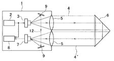
図6は測距部1のより具体的な説明図である。
【0007】
発光素子3の側にはLED、LD等の発光素子3からの測距光4を遮る様にチョッパー17が設けられ、該チョッパー17は光路変換モータ18により回転される。受光素子7の側には濃度フィルター20が反射測距光4′を遮断する様に設けられ、該濃度フィルター20は濃度調整モータ21により回転される。前記受光素子7としては、受光感度等の条件によりAPD(アバランシェ・フォト・ダイオード)が用いられる。
【0008】
前記チョッパー17には内側の光束と外側の光束とを交互に遮断する様なパターンが形成されており、前記光路変換モータ18により前記チョッパー17を回転することで、光路が交互に切替えられる様になっている。又、濃度フィルター20には、回転方向に沿って濃度が漸次変化する様なパターンが形成され、前記濃度調整モータ21で濃度フィルター20の回転位置を選択することで、前記受光素子7の受光光量を調整できる様になっている。前記反射プリズム6と距離測定機との距離に対応して受光素子7に入射する反射測距光4′の光量が増減するが、前記濃度フィルター20の位置を適宜選択することで前記受光素子7の受光光量を一定にすることができる。
【0009】
而して、前記受光素子7の受光光量に基づいて、前記受光素子7に入射する反射測距光4′と内部参照光12の光量が一定となる様に、前記濃度調整モータ21が回転され、前記濃度フィルター20の位置が制御される。又、前記測距回路8が発する基準信号と同期して、前記光路変換モータ18が回転制御され、前記受光素子7に入射する反射測距光4′と前記内部参照光12との切替えを行う。
【0010】
上記したAPDは受光感度の精度が高く、ダイナミックレンジが広い為、受光素子として用いられるが、APDは個々の素子に応じて特性のバラツキがあり、距離測定機に組込む場合には調整を必要とする。特に、高精度の測定機の場合には、調整は不可欠である。
【0011】
APDはバイアス電圧によって受光して流れる電流の倍率が調整出来る。APDのバイアス電圧と出力電流との特性を図7に示す。図7に示される様に、APDは使用可能な範囲の倍率が大きく、150倍以上取れるが、ある一定のバイアス電圧Va以上になると、雪崩現象を起こしてしまう特性がある。従って、APDの調整では必要な倍率を維持しつつ、雪崩現象を起こすバイアス電圧より低いバイアス電圧に設定される。
【0012】
従来のAPDの調整について説明する。
【0013】
従来この調整用として、専用の調整工具を必要とした。
【0014】
図8に示される様に、従来の調整工具は調整用のLED22と濃度フィルタ23の組合わせから成っている。
【0015】
先ず、出力光量が決められ一定とされた前記LED22を受光素子7に対して所定位置で発光させる。発光は実際の測距光4と同様に変調されている。
【0016】
APDがLED22からの光を直接受光し、光電変換した値から調整するが、その時の倍率を1倍とする。
【0017】
次に、1/150の濃度フィルタ23を、前記受光素子7と前記LED22との間に挿入する。前記APDの受光光量は1/150となり、受光光量が1/150に落ちたところで、APDからの出力電流が濃度フィルタ23が無い時と同じとなる様にバイアス電圧を上げて行く。同じとなったバイアス電圧で150倍の倍率が得られる。
【0018】
【発明が解決しようとする課題】
然し乍ら、この様に調整した受光素子7も、距離測定機の使用頻度、時間的経過等により、150倍に設定した時の正確な出力電流が得られなくなることがある。その場合には、製品の再調整が必要となる。この為、従来では定期的、或は所定使用時間毎に距離測定機の再調整を行っていた。上記した様に、調整には専用の調整工具、測定器械を必要とするので、距離測定機の使用者が随時調整を行うということができず、メーカに再調整を依頼していた。この為、再調整の度に距離測定機をメーカに持込む等煩雑であったと共に、再調整している間は距離測定機が使用できず、不便であった。
【0019】
本発明は斯かる実情に鑑み、受光素子(APD)を簡便に調整できる様にし、再調整に伴う煩雑さを解消すると共に距離測定機が再調整による使用の制限を受けない様にするものである。
【0020】
【課題を解決するための手段】
本発明は、測定対象に向けて測距光を照射する発光部と、測定対象物からの反射測定光を受光する受光部を有し距離を測定する距離測定機に於いて、前記受光部の受光感度をバイアス電圧により変化させる倍率調整部と、該受光部に向けて前記発光部の光量を可変可能とする光量切換え部とを具備する距離測定機に係り、又、前記発光部が測距光を発する光源と、調整用規定光を発する調整用発光素子を有し、前記光量切換え部は前記調整用発光素子の光量を可変とした距離測定機に係るものであり、又測定対象に向けて測定光を照射する発光部と、測定対象物からの反射測定光を受光する受光素子を有し距離を測定する距離測定機に於いて、前記発光部が前記受光素子に向けて複数の規定光量の光を照射可能であり、光量変化に対応させ前記受光素子の受光感度範囲を決定する距離測定機の受光部調整方法に係り、又前記発光部が測距光を発する光源と、調整用規定光を発する調整用発光素子を有し、該調整用発光素子の光量を可変とした距離測定機の受光部調整方法に係り、又前記発光部が規定光量に対し所定倍率で減光し、減光した状態に対して受光素子の所定倍率の感度が得られる様バイアス電圧を決定する距離測定機の受光部調整方法に係り、更に又前記発光部が複数段階の規定光量の光を順次発し、前記受光素子は発光部の発光光量に応じて順次バイアス電圧を変え、前記発光部が所定の複数段階の発光を終えた時点で前記受光素子のバイアス電圧を決定する距離測定機の受光部調整方法に係るものである。
【0021】
【発明の実施の形態】
以下、図面を参照しつつ本発明の実施の形態を説明する。
【0022】
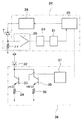
図1は距離測定機の受光感度調整部を示すものであり、該受光感度調整部は倍率調整部24と光量切換え部38から構成される。前記倍率調整部24は制御部25、該制御部25によりバイアス電圧の出力が制御されるバイアス回路26、該バイアス回路26によりバイアス電圧が印加される受光素子7、該受光素子7からの分岐電流値を調整する抵抗27、前記受光素子7の出力分岐電流を増幅する増幅器28、該増幅器28からの出力値のピーク値をホールドするピークホールド回路29、該ピークホールド回路29からの出力値をデジタル信号に変換するA/D変換器31とを具備する。
【0023】
又、前記光量切換え部38は、調整用発光素子32と該調整用発光素子32に第1スイッチングトランジスタ33及び第1抵抗34と第2スイッチングトランジスタ35及び第2抵抗36とが並列接続され、前記第1抵抗34の抵抗値(図では10Ω)を前記第2抵抗36の抵抗値(図では100Ω)の1/10とする。前記第1スイッチングトランジスタ33、第2スイッチングトランジスタ35にはON/OFF用制御電圧を印加する切換え回路37が接続され、該切換え回路37は前記制御部25により制御される様になっている。
【0024】
前記調整用発光素子32から発光される調整用規定光は前記受光素子7に入射する様になっており、図6で示した測距光学系とは別の倍率調整用の光学系を有している。
【0025】
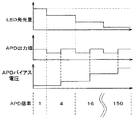
図2を参照して作用を説明する。
【0026】
距離測定機を所定時間使用後、或は所定期間毎に受光素子7の倍率調整を行う。
【0027】
前記発光素子3の発光を停止し、前記調整用発光素子32を発光させる。
【0028】
先ず、前記第2スイッチングトランジスタ35に対する制御電圧をOFFとし、前記第1スイッチングトランジスタ33に制御電圧を印加する。前記第1抵抗34で決定される初期駆動電流が前記調整用発光素子32に流れ、該調整用発光素子32が発光する。前記受光素子7には前記バイアス回路26より基準バイアス電圧が印加されており、前記バイアス回路26は基準バイアス電圧と前記調整用発光素子32からの光量により決定される電流が出力され、出力電流の基準ピーク値が前記ピークホールド回路29、A/D変換器31により検出され、前記制御部25に入力される。該制御部25はこの基準ピーク値を記憶する。
【0029】
次に、前記制御部25から前記切換え回路37に光量切換え指令信号が発せられ、該切換え回路37は前記第1スイッチングトランジスタ33に対する制御電圧をOFFとし、前記第2スイッチングトランジスタ35に制御電圧を印加する。前記調整用発光素子32には前記第2抵抗36により決定される変更駆動電流が流れ、発光する。該変更駆動電流は前記基準駆動電流の1/10であり、発光光量は1/10に減光する。
【0030】
減光状態での前記受光素子7からの出力電流値を前記ピークホールド回路29、A/D変換器31により検出し、前記制御部25が最低倍率ピーク値として記憶する。
【0031】
前記制御部25が前記バイアス回路26にバイアス電圧増加信号を発し、該バイアス回路26は前記受光素子7に印加するバイアス電圧を増大させる。前記受光素子7が出力する電流値は前記ピークホールド回路29、A/D変換器31から前記制御部25にフィードバックされ、フィードバックされた出力電流が前記基準ピーク値の15倍となる迄、前記バイアス回路26を制御する。前記制御部25は受光素子7の出力電流が前記基準ピーク値の15倍となった時点でのピーク値を最高倍率ピーク値として記憶すると共にこの時点でのバイアス電圧を最高倍率バイアス電圧として記憶する。
【0032】
而して、前記調整用発光素子32の減光状態での前記受光素子7の最低倍率ピーク値と最高倍率ピーク値との比は150倍となっており、バイアス電圧を前記基準バイアス電圧から最高倍率バイアス電圧迄変化させることで、前記受光素子7の受光感度を150倍とすることができる。
【0033】
尚、設定倍率は150倍に限らず、受光素子7の出力電流が前記基準ピーク値の10倍となった時点でのピーク値を最高倍率ピーク値として記憶すると共にこの時点でのバイアス電圧を最高倍率バイアス電圧として記憶すれば、受光感度は100倍となる等任意である。又、上記実施の形態では切換え回路37を別途設けたが、前記発光素子3による内部参照光12、反射測距光4′を利用し、前記発光素子3の発光量を変化させてもよい。
【0034】
図3により他の実施の形態について説明する。
【0035】
該他の実施の形態の受光感度調整部については特に図示しないが、回路構成としては上記実施の形態と同様であり、前記調整用発光素子32に3以上のスイッチング素子を並列に接続し、前記切換え回路37により3段階以上の光量切換えを行う様にしたものである。以下、図1を参照して説明する。
【0036】
調整用発光素子32の光量を光量切換え部38により段階的に下げ、その段階毎の受光素子7の出力電流が基準値となる様に、前記制御部25によりバイアス回路26を制御し、同じく段階的にバイアス電圧を上げていき、最終的に150倍の倍率を得る。
【0037】
前記調整用発光素子32を所定の光量で発光させる。この時のバイアス電圧の受光素子7の出力を倍率1倍とする。光量は使用するメーカの受光素子7特性から予め決めておく。この時点のバイアス電圧は非常に低くほとんど0Vに近い。この時の受光素子7の出力電流値をサンプリングし、A/D変換し基準ピーク値を検出して、前記制御部25により記憶する。
【0038】
次に、前記制御部25により前記光量切換え部38を制御し、調整用発光素子32の光量を次の段階の光量に下げる。この時受光素子7の出力電流から検出したピーク値は光量に応じて下がる。この降下を補う様に、ピーク値が基準ピーク値となる様に前記バイアス回路26を制御し、バイアス電圧を上げる。
【0039】
而して、調整用発光素子32の光量減少と、ピーク値が基準ピーク値となる様にバイアス電圧の増大とを繰返し、最終的に所定の倍率である150倍で調整を終える。
【0040】
尚、上記実施の形態では光量の切換えを電気的に行ったが、濃度フィルタを用いて光量の切換えを行ってもよい。又、前記距離測定機に対し、反射プリズム6を低地に配置し、前記反射測距光4′と前記濃度フィルター20を利用し、前記受光素子7が受光する光量の切換えを行ってもよい。
【0041】
【発明の効果】
以上述べた如く本発明によれば、測定対象に向けて測定光を照射する発光部と、測定対象物からの反射測定光を受光する受光素子を有し距離を測定する距離測定機に於いて、前記発光部が前記受光素子に向けて複数の規定光量の光を照射可能であり、光量変化に対応させ前記受光素子の受光感度範囲を決定する様にしたので、濃度フィルタを使用せずに受光素子(APD)の感度調整が行え、構造が簡単であると共に調整作業が簡便であり、再調整に伴う煩雑さが解消されると共に距離測定機が再調整による使用の制限を受けないという優れた効果を発揮する。
【図面の簡単な説明】
【図1】本発明の実施の形態の要部を示す回路構成図である。
【図2】同前本発明の実施の形態を示す作用説明図である。
【図3】本発明の他の実施の形態を示す作用説明図である。
【図4】距離測定機の測距部の概略説明図である。
【図5】測距部のブロック図である。
【図6】距離測定機の測距部の説明図である。
【図7】距離測定機に使用される受光素子の感度特性を示す線図である。
【図8】従来の調整用発光素子の調整工具の概略を示す説明図である。
【符号の説明】
3 発光素子
4 測距光
7 受光素子
12 内部参照光
24 倍率調整部
25 制御部
26 バイアス回路
29 ピークホールド回路
32 調整用発光素子
33 第1スイッチングトランジスタ
35 第2スイッチングトランジスタ
37 切換え回路
38 光量切換え部[0001]
BACKGROUND OF THE INVENTION
The present invention relates to a distance measuring device and a light receiving unit adjustment method for a distance measuring device that can easily adjust the sensitivity of a light receiving unit of a distance measuring unit.
[0002]
[Prior art]
The distance measurement by the light wave uses the modulated measurement light and obtains the distance from the phase difference of the reflected light. 4 is an explanatory diagram of the basic
[0003]
When the
[0004]
The distance measuring
[0005]
The distance to the measurement target (reflecting prism 6) obtained by the
[0006]
FIG. 6 is a more specific explanatory diagram of the
[0007]
A
[0008]
The
[0009]
Thus, based on the amount of light received by the
[0010]
The above APD is used as a light receiving element because of its high light receiving sensitivity accuracy and wide dynamic range. However, the APD has characteristic variations depending on the individual elements, and adjustment is required when it is incorporated into a distance measuring device. To do. In particular, in the case of a high-precision measuring machine, adjustment is essential.
[0011]
The APD can adjust the magnification of the current flowing by receiving light by the bias voltage. The characteristics of the APD bias voltage and output current are shown in FIG. As shown in FIG. 7, the APD has a large usable range magnification and can be obtained 150 times or more, but has an avalanche phenomenon when it exceeds a certain bias voltage Va. Therefore, in the APD adjustment, a bias voltage lower than the bias voltage causing the avalanche phenomenon is set while maintaining a necessary magnification.
[0012]
Conventional APD adjustment will be described.
[0013]
Conventionally, a special adjustment tool is required for this adjustment.
[0014]
As shown in FIG. 8, the conventional adjustment tool includes a combination of an
[0015]
First, the
[0016]
The APD directly receives the light from the
[0017]
Next, a 1/150
[0018]
[Problems to be solved by the invention]
However, the
[0019]
In view of such a situation, the present invention makes it possible to easily adjust the light receiving element (APD), eliminate the troublesomeness associated with the readjustment, and prevent the distance measuring device from being restricted by the readjustment. is there.
[0020]
[Means for Solving the Problems]
The present invention relates to a distance measuring machine that has a light emitting unit that irradiates distance measuring light toward a measurement target and a light receiving unit that receives reflected measurement light from the measurement target and measures the distance. The present invention relates to a distance measuring device including a magnification adjustment unit that changes a light receiving sensitivity by a bias voltage, and a light amount switching unit that can change a light amount of the light emitting unit toward the light receiving unit. A light source that emits light and an adjustment light-emitting element that emits adjustment-specific light, and the light amount switching unit relates to a distance measuring machine in which the light amount of the adjustment light-emitting element is variable, and is directed toward a measurement target In a distance measuring machine that has a light emitting unit that irradiates measurement light and a light receiving element that receives reflected measurement light from a measurement object and measures a distance, the light emitting unit has a plurality of prescribed points toward the light receiving element. It is possible to irradiate with a large amount of light, The present invention relates to a method for adjusting a light receiving unit of a distance measuring device that determines a light receiving sensitivity range of a light receiving element, and the light emitting unit includes a light source that emits distance measuring light and a light emitting element for adjustment that emits a specified light for adjustment. The present invention relates to a method of adjusting a light receiving unit of a distance measuring device in which the light amount of a light emitting element is variable. In accordance with a method of adjusting a light receiving unit of a distance measuring device that determines a bias voltage, the light emitting unit sequentially emits light of a predetermined amount of light in a plurality of stages, and the light receiving element sequentially biases according to the light emitting amount of the light emitting unit. The present invention relates to a method for adjusting a light receiving part of a distance measuring machine, wherein the voltage is changed and the bias voltage of the light receiving element is determined when the light emitting part finishes light emission of a predetermined plurality of stages.
[0021]
DETAILED DESCRIPTION OF THE INVENTION
Hereinafter, embodiments of the present invention will be described with reference to the drawings.
[0022]
FIG. 1 shows a light receiving sensitivity adjusting unit of a distance measuring device, and the light receiving sensitivity adjusting unit includes a
[0023]
The light
[0024]
The adjustment-specific light emitted from the adjustment light-emitting
[0025]
The operation will be described with reference to FIG.
[0026]
The magnification of the
[0027]
The
[0028]
First, the control voltage for the
[0029]
Next, a light amount switching command signal is issued from the
[0030]
The output current value from the
[0031]
The
[0032]
Thus, the ratio of the minimum magnification peak value and the maximum magnification peak value of the
[0033]
The set magnification is not limited to 150 times, and the peak value at the time when the output current of the
[0034]
Another embodiment will be described with reference to FIG.
[0035]
The light-receiving sensitivity adjustment unit of the other embodiment is not particularly illustrated, but the circuit configuration is the same as that of the above-described embodiment, and three or more switching elements are connected in parallel to the adjustment light-emitting
[0036]
The light amount of the adjustment
[0037]
The adjustment
[0038]
Next, the
[0039]
Thus, the light amount of the adjustment
[0040]
In the above embodiment, the light amount is switched electrically, but the light amount may be switched using a density filter. In addition, the reflecting prism 6 may be disposed at a low altitude with respect to the distance measuring device, and the amount of light received by the
[0041]
【The invention's effect】
As described above, according to the present invention, in the distance measuring apparatus that has the light emitting unit that irradiates the measurement light toward the measurement target and the light receiving element that receives the reflected measurement light from the measurement target, the distance measuring device measures the distance. The light emitting unit can irradiate a plurality of prescribed light amounts toward the light receiving element, and the light receiving sensitivity range of the light receiving element is determined in response to the light amount change, so that a density filter is not used. The sensitivity of the light receiving element (APD) can be adjusted, the structure is simple, the adjustment work is simple, the complexity associated with readjustment is eliminated, and the distance measuring machine is not subject to restrictions on use due to readjustment. Show the effect.
[Brief description of the drawings]
FIG. 1 is a circuit configuration diagram showing a main part of an embodiment of the present invention.
FIG. 2 is an operation explanatory view showing an embodiment of the present invention.
FIG. 3 is an operation explanatory view showing another embodiment of the present invention.
FIG. 4 is a schematic explanatory diagram of a distance measuring unit of the distance measuring machine.
FIG. 5 is a block diagram of a distance measuring unit.
FIG. 6 is an explanatory diagram of a distance measuring unit of the distance measuring device.
FIG. 7 is a diagram showing sensitivity characteristics of a light receiving element used in a distance measuring machine.
FIG. 8 is an explanatory view showing an outline of a conventional adjustment tool for a light-emitting element for adjustment.
[Explanation of symbols]
3 Light-Emitting
Claims (5)
Priority Applications (3)
| Application Number | Priority Date | Filing Date | Title |
|---|---|---|---|
| JP34726699A JP4630413B2 (en) | 1999-12-07 | 1999-12-07 | Distance measuring machine and light receiving unit adjusting method of distance measuring machine |
| US09/726,143 US6693703B2 (en) | 1999-12-07 | 2000-11-29 | Distance measuring device and method for adjusting photodetection unit of distance measuring device |
| EP00310876.8A EP1106963B1 (en) | 1999-12-07 | 2000-12-07 | Distance measuring device and method for adjusting photodetection unit |
Applications Claiming Priority (1)
| Application Number | Priority Date | Filing Date | Title |
|---|---|---|---|
| JP34726699A JP4630413B2 (en) | 1999-12-07 | 1999-12-07 | Distance measuring machine and light receiving unit adjusting method of distance measuring machine |
Publications (3)
| Publication Number | Publication Date |
|---|---|
| JP2001165654A JP2001165654A (en) | 2001-06-22 |
| JP2001165654A5 JP2001165654A5 (en) | 2007-02-01 |
| JP4630413B2 true JP4630413B2 (en) | 2011-02-09 |
Family
ID=18389062
Family Applications (1)
| Application Number | Title | Priority Date | Filing Date |
|---|---|---|---|
| JP34726699A Expired - Fee Related JP4630413B2 (en) | 1999-12-07 | 1999-12-07 | Distance measuring machine and light receiving unit adjusting method of distance measuring machine |
Country Status (3)
| Country | Link |
|---|---|
| US (1) | US6693703B2 (en) |
| EP (1) | EP1106963B1 (en) |
| JP (1) | JP4630413B2 (en) |
Families Citing this family (7)
| Publication number | Priority date | Publication date | Assignee | Title |
|---|---|---|---|---|
| US6762846B1 (en) | 2002-09-19 | 2004-07-13 | Nanometrics Incorporated | Substrate surface profile and stress measurement |
| US20050230605A1 (en) * | 2004-04-20 | 2005-10-20 | Hamid Pishdadian | Method of measuring using a binary optical sensor |
| JP4855749B2 (en) * | 2005-09-30 | 2012-01-18 | 株式会社トプコン | Distance measuring device |
| JP2008270558A (en) * | 2007-04-20 | 2008-11-06 | Sumitomo Electric Ind Ltd | Method for adjusting light receiving module |
| JP6045963B2 (en) * | 2013-04-05 | 2016-12-14 | 日立マクセル株式会社 | Optical distance measuring device |
| WO2021182224A1 (en) * | 2020-03-11 | 2021-09-16 | 株式会社デンソー | Measuring device |
| WO2022039871A1 (en) * | 2020-08-17 | 2022-02-24 | Beijing Voyager Technology Co. Ltd. | Dynamic receiver gain control for lidar system |
Citations (4)
| Publication number | Priority date | Publication date | Assignee | Title |
|---|---|---|---|---|
| JPS5110984A (en) * | 1974-06-05 | 1976-01-28 | Aga Ab | |
| JPS60149929A (en) * | 1984-11-26 | 1985-08-07 | Tokyo Optical Co Ltd | Temperature compensator for avalanche diode |
| JPH0346588A (en) * | 1989-07-13 | 1991-02-27 | Mitsubishi Electric Corp | Laser receiver |
| JPH0854468A (en) * | 1994-08-10 | 1996-02-27 | Nikon Corp | Photoreceiver |
Family Cites Families (7)
| Publication number | Priority date | Publication date | Assignee | Title |
|---|---|---|---|---|
| US3815994A (en) * | 1972-03-31 | 1974-06-11 | Kaman Sciences Corp | System and method for measuring distance |
| CH634419A5 (en) * | 1978-10-11 | 1983-01-31 | Kern & Co Ag | METHOD FOR ELECTROOPTIC DISTANCE MEASUREMENT AND DEVICE FOR IMPLEMENTING THE METHOD. |
| US4464048A (en) * | 1981-03-25 | 1984-08-07 | Barr & Stroud Limited | Laser rangefinders |
| US5396510A (en) * | 1993-09-30 | 1995-03-07 | Honeywell Inc. | Laser sensor capable of measuring distance, velocity, and acceleration |
| JP2951547B2 (en) * | 1994-10-03 | 1999-09-20 | 浜松ホトニクス株式会社 | Lightwave distance meter and distance measurement method |
| US5691808A (en) * | 1995-07-31 | 1997-11-25 | Hughes Electronics | Laser range finder receiver |
| DE19643287A1 (en) * | 1996-10-21 | 1998-04-23 | Leica Ag | Method and device for calibrating distance measuring devices |
-
1999
- 1999-12-07 JP JP34726699A patent/JP4630413B2/en not_active Expired - Fee Related
-
2000
- 2000-11-29 US US09/726,143 patent/US6693703B2/en not_active Expired - Lifetime
- 2000-12-07 EP EP00310876.8A patent/EP1106963B1/en not_active Expired - Lifetime
Patent Citations (4)
| Publication number | Priority date | Publication date | Assignee | Title |
|---|---|---|---|---|
| JPS5110984A (en) * | 1974-06-05 | 1976-01-28 | Aga Ab | |
| JPS60149929A (en) * | 1984-11-26 | 1985-08-07 | Tokyo Optical Co Ltd | Temperature compensator for avalanche diode |
| JPH0346588A (en) * | 1989-07-13 | 1991-02-27 | Mitsubishi Electric Corp | Laser receiver |
| JPH0854468A (en) * | 1994-08-10 | 1996-02-27 | Nikon Corp | Photoreceiver |
Also Published As
| Publication number | Publication date |
|---|---|
| US6693703B2 (en) | 2004-02-17 |
| EP1106963A3 (en) | 2003-08-06 |
| EP1106963B1 (en) | 2014-07-02 |
| JP2001165654A (en) | 2001-06-22 |
| EP1106963A2 (en) | 2001-06-13 |
| US20010002860A1 (en) | 2001-06-07 |
Similar Documents
| Publication | Publication Date | Title |
|---|---|---|
| JP3161738B2 (en) | Equipment for calibration of distance measuring instruments | |
| US4412744A (en) | Absolute spectrophotometer | |
| JP5690541B2 (en) | Distance measuring device | |
| KR101016565B1 (en) | Device and method for distance measurement | |
| JP4630413B2 (en) | Distance measuring machine and light receiving unit adjusting method of distance measuring machine | |
| US4707838A (en) | Current supply for radiation sources of frequency-proportional optical sensors | |
| US6965357B2 (en) | Light-emitting element drive circuit | |
| JP2006329797A (en) | Light wave range finder | |
| US7546008B2 (en) | Variable optical attenuator and ranging apparatus using the same | |
| US20070127530A1 (en) | Laser control | |
| JPH11230740A (en) | Distance measurement device | |
| JP3778119B2 (en) | Power control apparatus and method for optical disk recording | |
| US6870618B2 (en) | Wavelength characteristic measuring device and method using light having wavelength thereof continuously changed | |
| CN111965805A (en) | Illumination device and illumination method for optical microscope | |
| JP2002374033A (en) | Variable wavelength light source device | |
| JP5127677B2 (en) | Light source control circuit and direct exposure apparatus | |
| KR100903090B1 (en) | Infrared laser illuminator | |
| US20220291493A1 (en) | Illumination device for a confocal microscope | |
| JP3977511B2 (en) | Emitter / receiver | |
| JP2002324909A (en) | Photoelectric conversion circuit and laser range finder | |
| JP3737771B2 (en) | Light level multi-step distance measuring device | |
| JP2761269B2 (en) | camera | |
| JPH0567827A (en) | Laser power controller | |
| JPH0735984A (en) | Illuminator for optical measuring machine | |
| KR20000031966A (en) | Apparatus for controlling level focus of projection lens |
Legal Events
| Date | Code | Title | Description |
|---|---|---|---|
| A521 | Written amendment |
Free format text: JAPANESE INTERMEDIATE CODE: A523 Effective date: 20061204 |
|
| A621 | Written request for application examination |
Free format text: JAPANESE INTERMEDIATE CODE: A621 Effective date: 20061204 |
|
| A977 | Report on retrieval |
Free format text: JAPANESE INTERMEDIATE CODE: A971007 Effective date: 20091217 |
|
| A131 | Notification of reasons for refusal |
Free format text: JAPANESE INTERMEDIATE CODE: A131 Effective date: 20091222 |
|
| A521 | Written amendment |
Free format text: JAPANESE INTERMEDIATE CODE: A523 Effective date: 20100222 |
|
| A131 | Notification of reasons for refusal |
Free format text: JAPANESE INTERMEDIATE CODE: A131 Effective date: 20100608 |
|
| A521 | Written amendment |
Free format text: JAPANESE INTERMEDIATE CODE: A523 Effective date: 20100804 |
|
| TRDD | Decision of grant or rejection written | ||
| A01 | Written decision to grant a patent or to grant a registration (utility model) |
Free format text: JAPANESE INTERMEDIATE CODE: A01 Effective date: 20101109 |
|
| A01 | Written decision to grant a patent or to grant a registration (utility model) |
Free format text: JAPANESE INTERMEDIATE CODE: A01 |
|
| A61 | First payment of annual fees (during grant procedure) |
Free format text: JAPANESE INTERMEDIATE CODE: A61 Effective date: 20101115 |
|
| FPAY | Renewal fee payment (event date is renewal date of database) |
Free format text: PAYMENT UNTIL: 20131119 Year of fee payment: 3 |
|
| R150 | Certificate of patent or registration of utility model |
Free format text: JAPANESE INTERMEDIATE CODE: R150 |
|
| R250 | Receipt of annual fees |
Free format text: JAPANESE INTERMEDIATE CODE: R250 |
|
| R250 | Receipt of annual fees |
Free format text: JAPANESE INTERMEDIATE CODE: R250 |
|
| R250 | Receipt of annual fees |
Free format text: JAPANESE INTERMEDIATE CODE: R250 |
|
| R250 | Receipt of annual fees |
Free format text: JAPANESE INTERMEDIATE CODE: R250 |
|
| LAPS | Cancellation because of no payment of annual fees |