JP4630252B2 - Moore - Google Patents

Moore Download PDF

Info

Publication number
JP4630252B2
JP4630252B2 JP2006256043A JP2006256043A JP4630252B2 JP 4630252 B2 JP4630252 B2 JP 4630252B2 JP 2006256043 A JP2006256043 A JP 2006256043A JP 2006256043 A JP2006256043 A JP 2006256043A JP 4630252 B2 JP4630252 B2 JP 4630252B2
Authority
JP
Japan
Prior art keywords
cutting blade
discharge port
plate portion
blade housing
housing
Prior art date
Legal status (The legal status is an assumption and is not a legal conclusion. Google has not performed a legal analysis and makes no representation as to the accuracy of the status listed.)
Active
Application number
JP2006256043A
Other languages
Japanese (ja)
Other versions
JP2008072960A (en
Inventor
善幸 江崎
正敏 山口
和生 小池
Current Assignee (The listed assignees may be inaccurate. Google has not performed a legal analysis and makes no representation or warranty as to the accuracy of the list.)
Kubota Corp
Original Assignee
Kubota Corp
Priority date (The priority date is an assumption and is not a legal conclusion. Google has not performed a legal analysis and makes no representation as to the accuracy of the date listed.)
Filing date
Publication date
Application filed by Kubota Corp filed Critical Kubota Corp
Priority to JP2006256043A priority Critical patent/JP4630252B2/en
Priority to US11/726,370 priority patent/US7437865B2/en
Publication of JP2008072960A publication Critical patent/JP2008072960A/en
Application granted granted Critical
Publication of JP4630252B2 publication Critical patent/JP4630252B2/en
Active legal-status Critical Current
Anticipated expiration legal-status Critical

Links

Images

Description

本発明は、刈り刃ハウジングの内部に刈り刃ハウジング横方向に並んで位置するとともに刈り刃ハウジング上下向き軸芯まわりで回転自在な複数の回転刈り刃と、前記刈り刃ハウジングの横一端部に位置した刈り草排出口と、前記各回転刈り刃からの刈り草を前記刈り草排出口に流動案内するよう、前記刈り刃ハウジングの内部の前記各回転刈り刃の回転域の前方に位置した前バッフルプレートとを備えたモーアに関する。   The present invention relates to a plurality of rotary cutting blades that are positioned side by side in the horizontal direction of the cutting blade housing inside the cutting blade housing and that are rotatable around the vertical axis of the cutting blade housing, and are positioned at one end of the cutting blade housing. And a front baffle positioned in front of the rotation area of each rotary cutting blade inside the cutting blade housing so as to flow-guide the cut grass from each rotary cutting blade to the cutting grass discharge port. It relates to a mower with a plate.

上記したモーアは、回転刈り刃によって切断処理された刈り草を、各回転刈り刃の回転によって発生し、前バッフルプレートに案内されて刈り刃ハウジング内を刈りハウジングの横一端側に向けて流動する風によって搬送し、刈り草排出口から刈り刃ハウジング外に排出する。   The mower described above is generated by the rotation of each rotary cutting blade, and the mowing grass cut by the rotary cutting blade is guided by the front baffle plate and flows in the cutting blade housing toward the lateral end of the cutting housing. It is conveyed by wind and discharged out of the cutting blade housing through the cut grass outlet.

この種のモーアとして、従来、たとえば特許文献1に示されるものがあった。特許文献1に示されるものは、モーアデッキ(刈り刃ハウジングに相当)と、3枚の回転ブレード(回転刈り刃に相当)と、刈り草排出口と、前部バッフル(前バッフルプレートに相当)とを備えている。前部バッフルは、刈り草搬送方向での最下手の回転ブレード(刈り草排出口に最も近い最排出口側刈り刃に相当)の回転域と、刈り草搬送方向での中央の回転ブレード(最排出口側刈り刃に隣り合った隣り刈り刃に相当)の回転域との前方に位置するプレート部を備えている。このプレート部は、中央の回転ブレードの回転域に沿った湾曲形の上手側プレート部分と、最下手の回転ブレードの回転域の前方に位置した下手側プレート部分とを備えている。下手側プレート部分は、刈り草排出口に近い直線状の案内終端側部分と、この案内終端側部分と前記湾曲プレート部分とにわたっている案内始端側部分とを備えている。前記案内始端側部分は、波形になり、中央の回転ブレードの回転域と最下手の回転ブレードの回転域とに比較的近く位置している。   Conventionally, as this type of mower, for example, there is one shown in Patent Document 1. Patent Document 1 shows a moor deck (corresponding to a cutting blade housing), three rotating blades (corresponding to a rotating cutting blade), a cut grass discharge port, a front baffle (corresponding to a front baffle plate), It has. The front baffle consists of the rotation zone of the lowermost rotating blade (corresponding to the cutting blade side cutting blade closest to the cutting grass discharge port) in the cutting grass conveying direction and the central rotating blade (most in the cutting grass conveying direction). A plate portion located in front of the rotation area of the adjacent cutting blade adjacent to the discharge-side cutting blade. The plate portion includes a curved upper side plate portion along the rotation range of the central rotary blade, and a lower side plate portion positioned in front of the rotation range of the lowermost rotary blade. The lower plate portion includes a linear guide terminal portion near the cut grass discharge port, and a guide start end portion extending over the guide terminal portion and the curved plate portion. The guide start end portion has a corrugated shape and is located relatively close to the rotation region of the central rotary blade and the rotation region of the lowermost rotary blade.

特開2004−41060号公報(段落〔0027〕−〔0029〕、図6)JP 2004-41060 A (paragraphs [0027]-[0029], FIG. 6)

この種のモーアは、隣り刈り刃からの風と最排出口側刈り刃からの風とが、隣り刈り刃の回転域と最排出口側刈り刃の回転域との間やこの付近で合流し、合流した風が前バッフルプレートに案内されて刈り草排出口に向けて流動する。上記した従来の前バッフルプレートに関する技術を採用した場合、隣り刈り刃からの風と最排出口側刈り刃からの風とが合流する部位およびこの付近において、速度の速い空気の流れや刈り刃ハウジング下方向きの強い風が発生し、草の倒伏が発生することがあった。このため、最排出口側刈り刃や隣り刈り刃による刈り跡に切断不足や刈残しの草が発生する場合があるなど、良好な刈跡を得にくくなる場合があった。   In this type of mower, the wind from the adjacent cutting blade and the wind from the most exhausting side cutting blade merge between or near the rotation area of the adjacent cutting blade and the rotation area of the most exhausting side cutting blade. The combined wind is guided by the front baffle plate and flows toward the cut grass discharge port. When the above-described conventional technology related to the front baffle plate is adopted, a high-speed air flow or cutting blade housing at and near the portion where the wind from the adjacent cutting blade and the wind from the most discharge port side cutting blade merge. A strong downward wind was generated, and grass lodging sometimes occurred. For this reason, there are cases where it is difficult to obtain a good cut mark, such as insufficient cutting or uncut grass in the cut mark by the most discharge port side cutting blade or the adjacent cutting blade.

本発明の目的は、上記したトラブル発生を回避しやすいモーアを提供することにある。   An object of the present invention is to provide a mower that can easily avoid the above-described trouble occurrence.

本第1発明は、刈り刃ハウジングの内部に刈り刃ハウジング横方向に並んで位置するとともに刈り刃ハウジング上下向き軸芯まわりで回転自在な複数の回転刈り刃と、前記刈り刃ハウジングの横一端部に位置した刈り草排出口と、前記各回転刈り刃からの刈り草を前記刈り草排出口に流動案内するよう、前記刈り刃ハウジングの内部の前記各回転刈り刃の回転域の前方に位置した前バッフルプレートとを備えたモーアにおいて、
前記前バッフルプレートのうち、前記複数の回転刈り刃のうちの前記刈り草排出口に最も近い最排出口側刈り刃の回転域と、前記最排出口側刈り刃に隣り合った隣り刈り刃の回転域との前方に位置するプレート部を、前記隣り刈り刃の回転域の前方に配置した屈曲点で刈り刃ハウジング前後方向に屈曲した屈曲プレート部に構成し、
前記プレート部の前記屈曲点よりも流動案内方向下手側に位置する下手側プレート部分を、この下手側プレート部分の流動案内終点と前記屈曲点とを通る直線よりも刈り刃ハウジング前方側に配置してある。
The first invention includes a plurality of rotary cutting blades positioned side by side in the horizontal direction of the cutting blade housing inside the cutting blade housing and rotatable around the vertical axis of the cutting blade housing, and a lateral end portion of the cutting blade housing The mowed grass outlet and the mowed grass from each rotary cutting blade are located in front of the rotation area of each rotary mow blade inside the cutting blade housing so as to flow guide the mowed grass from each rotary mow blade to the mowed grass outlet. In moor with front baffle plate,
Of the front baffle plate, of the plurality of rotary cutting blades, the rotation area of the nearest discharge port side cutting blade closest to the cut grass discharge port, and the adjacent cutting blade adjacent to the most discharge port side cutting blade The plate portion located in front of the rotation area is configured as a bent plate portion bent in the front-rear direction of the cutting blade housing at a bending point arranged in front of the rotation area of the adjacent cutting blade,
A lower plate portion located on the lower side of the flow guide direction with respect to the bending point of the plate portion is disposed on the front side of the cutting blade housing with respect to a straight line passing through the flow guide end point of the lower plate portion and the bending point. It is.

本第1発明の構成によると、隣り刈り刃からの風と最排出口側刈り刃からの風とが、隣り刈り刃の回転域と最排出口側刈り刃の回転域との間やこの付近で合流し、前バッフルプレートに案内されて刈り草排出口に向けて流動する。プレート部の屈曲点による屈曲、屈曲点の配置、下手側プレート部分の配置のために合流部位の広さも、合流部位から刈り草排出口に至る風路の広さも適切な広さになり、急速なあるいは強い空気流れや吹き降ろし風が発生しにくく、風による草倒伏を発生しにくくしながら刈り草排出を行わせることができる。   According to the configuration of the first aspect of the invention, the wind from the adjacent cutting blade and the wind from the most discharge port side cutting blade are between or near the rotation region of the adjacent cutting blade and the rotation region of the most discharge port side cutting blade. At this point, they are guided by the front baffle plate and flow toward the cut grass outlet. Because of the bending at the bending point of the plate part, the arrangement of the bending point, and the arrangement of the lower plate part, the size of the merging part and the width of the air path from the merging part to the cut grass discharge port are also appropriately widened and rapidly It is possible to cause the cut grass to be discharged while it is difficult for a strong air flow or a downwind to be generated, and to prevent a grassy fall caused by the wind.

従って、刈り草を回転刈り刃によって発生した風によって刈り刃ハウジングの横外側に排出するものでありながら、草の風による倒伏に起因した切断不足や刈り残しなどが発生しにくい良好な仕上がり状態に草刈り作業を行うことができる。   Therefore, the cut grass is discharged to the lateral outside of the cutting blade housing by the wind generated by the rotary cutting blade, but it has a good finish that is less prone to cutting shortage and uncut residue due to the lodging due to the wind of the grass. Mowing work can be performed.

本第2発明は、本第1発明の構成において、前記屈曲点は、前記隣り刈り刃の回転域のうちの隣り刈り刃の回転軸芯に対して前記刈り草排出口が位置する側に寄って位置している。   According to a second aspect of the present invention, in the configuration of the first aspect of the invention, the bending point is closer to a side where the cut grass discharge port is located with respect to a rotational axis of the adjacent cutting blade in a rotation area of the adjacent cutting blade. Is located.

本第2発明の構成によると、前バッフルプレートの隣り刈り刃に対応するプレート部分の長さを適切な長さにし、隣り刈り刃からの風に対する前バッフルプレートによる流動案内を適切に行わせることができる。   According to the structure of this 2nd invention, the length of the plate part corresponding to the adjacent cutting blade of a front baffle plate is made into an appropriate length, and the flow guide by the front baffle plate with respect to the wind from an adjacent cutting blade is performed appropriately. Can do.

従って、刈り草が刈り草排出口にスムーズに流動案内され、刈り草を刈り刃ハウジング内に滞留しにくいように円滑に排出させることができる。   Accordingly, the cut grass is smoothly guided to the cut grass discharge port, and the cut grass can be smoothly discharged so as not to stay in the cut blade housing.

以下、本発明の実施例を図面に基づいて説明する。
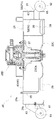
図1は、乗用型草刈機の全体側面図である。図2は、乗用型草刈機の全体平面図である。これらの図に示すように、乗用型草刈機は、左右一対の前車輪1,1と左右一対の後車輪2,2とを有した自走車体と、この自走車体の車体フレーム3の前輪1と後輪2との間にリンク機構4を介して装着された本発明の実施例に係るモーア20とを備えている。
Embodiments of the present invention will be described below with reference to the drawings.
FIG. 1 is an overall side view of a riding mower. FIG. 2 is an overall plan view of the riding mower. As shown in these drawings, the riding mower has a self-propelled vehicle body having a pair of left and right front wheels 1 and 1 and a pair of left and right rear wheels 2 and 2, and a front wheel of a body frame 3 of the self-propelled vehicle body. 1 and a rear wheel 2 are provided with a mower 20 according to an embodiment of the present invention mounted via a link mechanism 4.

この乗用型草刈機は、草刈りや芝刈り作業を行うものである。
すなわち、リンク機構4の左右一対の後揺動リンク4b,4bを一体揺動自在に支持している支軸4dに連結された昇降シリンダ14を操作すると、リンク機構4が昇降シリンダ14によって車体フレーム3に対して上下に揺動操作され、モーア20をゲージ輪25が地面に接地した下降作業状態と、ゲージ輪25が地面から上昇した上昇非作業状態とに昇降操作する。モーア20を下降作業状態にして自走車体を走行させると、モーア20は、刈り刃ハウジング21の内部に位置する3枚の回転刈り刃22L,22C,22R(図3参照)によって草や芝の刈り処理を行い、刈り草や刈り草(以下、これらを刈り草と称する。)を各回転刈り刃22L,22C,22Rの回転によって発生した風によって刈り刃ハウジング21の内部を刈り刃ハウジング21の横一端部に位置する刈り草排出口23(図3参照)に搬送し、この刈り草排出口23から放出ガイド24によって案内させながら自走車体横外側に放出する。
This riding mower performs mowing and lawn mowing work.
That is, when the lifting cylinder 14 connected to the support shaft 4d that supports the pair of left and right rear swing links 4b, 4b of the link mechanism 4 so as to be swingable integrally is operated, the link mechanism 4 is moved by the lifting cylinder 14 to the vehicle body frame. 3, the mower 20 is moved up and down into a descending working state in which the gauge wheel 25 is in contact with the ground and a non-working state in which the gauge wheel 25 is lifted from the ground. When the mower 20 is in the descending work state and the self-propelled vehicle body travels, the mower 20 moves the grass or turf by three rotary mowing blades 22L, 22C, and 22R (see FIG. 3) located inside the mowing blade housing 21. The mowing process is performed, and the inside of the mowing blade housing 21 is cut into the mowing blade housing 21 by the wind generated by the rotation of the rotating mowing blades 22L, 22C, and 22R. It is conveyed to the cut grass discharge port 23 (see FIG. 3) located at the lateral end, and discharged from the cut grass discharge port 23 to the lateral outer side of the self-propelled vehicle body while being guided by the discharge guide 24.

自走車体について詳述する。
自走車体は、前記左右一対の前車輪1,1と前記左右一対の後車輪2,2とを備える他、車体後部に設けたエンジン5を有した原動部と、運転座席6及び左右一対の操縦レバー7,7を有した運転部と、運転座席6の後側近くに位置した転倒保護枠8と、前記左右の後車輪2,2を支持する伝動装置9と、伝動装置9の前部に位置する動力取り出し軸10の駆動力をモーア20の刈り刃駆動機構20Dに伝達する回転軸11とを備えている。左右の前車輪1は、車体フレーム3の前部に連結された前輪支持フレーム12の端部に前輪支持フォーク13を介して遊転自在に支持されている。左右の前車輪1は、前輪支持フォーク13と共に前輪支持フレーム12に対して揺動操向する。左右の後車輪2,2は、伝動装置9が備える一対の静油圧式無段変速装置(図示せず)によって各別に駆動され、前記左右一対の操縦レバー7,7による一対の静油圧式無段変速装置の各別な変速操作によって各別に前進側及び後進側に変速され、かつ停止操作される。
The self-propelled vehicle body will be described in detail.
The self-propelled vehicle body includes the pair of left and right front wheels 1 and 1 and the pair of left and right rear wheels 2 and 2, a driving unit having an engine 5 provided at the rear of the vehicle body, a driver seat 6, and a pair of left and right vehicles. A driving unit having control levers 7, 7, a fall protection frame 8 located near the rear side of the driving seat 6, a transmission 9 that supports the left and right rear wheels 2, 2, and a front part of the transmission 9 And a rotating shaft 11 for transmitting the driving force of the power take-off shaft 10 located at the position to the cutting blade drive mechanism 20D of the mower 20. The left and right front wheels 1 are supported by the end portions of a front wheel support frame 12 connected to the front portion of the vehicle body frame 3 via a front wheel support fork 13 so as to be freely rotatable. The left and right front wheels 1 swing with respect to the front wheel support frame 12 together with the front wheel support forks 13. The left and right rear wheels 2, 2 are individually driven by a pair of hydrostatic continuously variable transmissions (not shown) provided in the transmission 9, and a pair of hydrostatic non-rotating wheels by the pair of left and right control levers 7, 7. The gears are shifted to the forward side and the reverse side individually by the respective shift operations of the step transmission and stopped.

次に、リンク機構4について詳述する。
リンク機構4は、車体フレーム3とモーア20の刈り刃ハウジング21の前端側とにわたって連結されて、モーア20の前端側を車体フレーム3に昇降自在に連結している左右一対の前揺動リンク4a,4aと、車体フレーム3と前記刈り刃ハウジング21の後端側とにわたって連結されて、モーア20の後端側を車体フレーム3に昇降自在に連結している左右一対の後揺動リンク4b,4bと、左右両側において前揺動リンク4aと後揺動リンク4bとにわたって連結された連動リンク4cとを備えている。
Next, the link mechanism 4 will be described in detail.
The link mechanism 4 is connected across the vehicle body frame 3 and the front end side of the cutting blade housing 21 of the mower 20, and a pair of left and right front swing links 4 a connecting the front end side of the mower 20 to the vehicle body frame 3 so as to be movable up and down. , 4a and a pair of left and right rear swing links 4b connected to the body frame 3 and the rear end side of the cutting blade housing 21 to connect the rear end side of the mower 20 to the body frame 3 so as to be movable up and down. 4b, and an interlocking link 4c connected to the front swing link 4a and the rear swing link 4b on both the left and right sides.

次に、モーア20について詳述する。図3は、モーア20の底面図である。図4は、モーア20の底面側からの斜視図である。
これらの図に示すように、モーア20は、前記刈り刃ハウジング21と、前記3枚の回転刈り刃22L,22R,22Cと、前記刈り草排出口23と、前記ゲージ輪25とを備える他、刈り刃ハウジング21の内部に各回転刈り刃22L,22R,22Cよりも前側に配置して設けた前バッフルプレート40と、刈り刃ハウジング21の内部に各回転刈り刃22L,22R,22Cよりも後側に配置して設けた後バッフルプレート50とを備えている。
Next, the mower 20 will be described in detail. FIG. 3 is a bottom view of the mower 20. FIG. 4 is a perspective view from the bottom side of the mower 20.
As shown in these drawings, the mower 20 includes the cutting blade housing 21, the three rotary cutting blades 22L, 22R, and 22C, the cut grass discharge port 23, and the gauge wheel 25, A front baffle plate 40 provided in the cutting blade housing 21 so as to be disposed in front of the rotary cutting blades 22L, 22R, and 22C, and a rear of the rotary cutting blades 22L, 22R, and 22C in the cutting blade housing 21. And a rear baffle plate 50 provided on the side.

刈り刃ハウジング21は、天板21aと、この天板21aの山形の前縁部から刈り刃ハウジング下方向きに延出した前縦壁21bと、天板21aの後縁部から刈り刃ハウジング下向きに延出した後縦壁21cと、天板21aの横端部から刈り刃ハウジング下向きに延出した横縦壁21dとによって構成され、自走機体下方向きに開口した容器形になっている。後縦壁21cは、この後縦壁21cの刈り刃ハウジング横方向での両端部に位置するとともに刈り刃ハウジング上下方向視で円弧形になった円弧形端部壁31と、前記一対の円弧形端部壁31,31の間に位置するとともに刈り刃ハウジング上下方向視で直線形になった直線形中間部壁32と備えている。刈り刃ハウジング21の前記刈り草排出口23は、天板21aと前縦壁21bと後縦壁21cとの端部によって形成されている。   The cutting blade housing 21 includes a top plate 21a, a front vertical wall 21b extending downward from the chevron-shaped front edge of the top plate 21a, and a cutting blade housing downward from the rear edge of the top plate 21a. The extended vertical wall 21c and the horizontal vertical wall 21d extending downward from the horizontal end portion of the top plate 21a downward from the cutting blade housing are formed into a container shape opened downward from the self-propelled machine body. The rear vertical wall 21c is positioned at both ends of the rear vertical wall 21c in the horizontal direction of the cutting blade housing and has an arcuate end wall 31 that has an arc shape when viewed in the vertical direction of the cutting blade housing, A straight intermediate wall 32 is provided between the arcuate end walls 31 and 31 and is linear when viewed in the vertical direction of the cutting blade housing. The cut grass discharge port 23 of the cutting blade housing 21 is formed by end portions of a top plate 21a, a front vertical wall 21b, and a rear vertical wall 21c.

図3,4に示すように、前記後縦壁21cは、この後縦壁21cの刈り刃ハウジング横幅方向での中央部に位置する部位としての前記直線形中間壁部32の中央部位に設けた通気口33と、この通気口33の両横側に配置して前記直線形中間壁部32に設けた第二通気口34とを備えている。前記各第二通気口34と前記通気口33とは、前記通気口33を挿通させて前記後バッフルプレート50の中央刈り刃対応部52と前記直線形中間壁部32とにわたって連結された左右一対の板金製の支持部材60,60のうちの第二通気口34に近い方の支持部材60を挟んだ位置関係になっている。前記各第二通気口34は、前記通気口33とで挟んでいる前記支持部材60の近くに配置されている。   As shown in FIGS. 3 and 4, the rear vertical wall 21c is provided at the central portion of the linear intermediate wall portion 32 as a portion located at the central portion of the rear vertical wall 21c in the horizontal direction of the cutting blade housing. A vent hole 33 and a second vent hole 34 provided in the straight intermediate wall portion 32 are provided on both sides of the vent hole 33. Each of the second vent holes 34 and the vent holes 33 is a pair of left and right pipes that are inserted through the vent holes 33 and connected to the central cutting blade corresponding portion 52 of the rear baffle plate 50 and the linear intermediate wall portion 32. Of the support members 60, 60 made of sheet metal, the support member 60 closer to the second vent 34 is sandwiched. Each of the second vent holes 34 is disposed near the support member 60 sandwiched between the vent holes 33.

図3,4に示すように、前記3枚の回転刈り刃22L,22R,22Cは、刈り刃ハウジング横方向に並んでいる。3枚の回転刈り刃22L,22R,22Cのうち、刈り刃ハウジング横方向での中央に位置する中央回転刈り刃22C(以下、中央刈り刃22Cと略称する。)は、刈り草排出口23から最も離れて存在し、かつ、刈り草流動方向での最上手に位置した最上手回転刈り刃22L(以下、最上手刈り刃22Lと略称する。)と、刈り草流動方向での最上手に位置し、かつ、刈り草排出口23の最も近くに位置した最排出口側回転刈り刃22R(以下、最排出口側刈り刃22Rと略称する。)とに対して若干刈り刃ハウジング前方側に位置ずれしている。各回転刈り刃22L,22R,22Cは、刈り刃ハウジング21の天板21aにベアリング支持ケースで成る支持部材26を介して回転自在に支持された刈り刃駆動軸27の下端部に一体回転自在に支持されている。これにより、各回転刈り刃22L,22C,22Rは、刈り刃駆動軸27が備える刈り刃ハウジング上下向き軸芯Xのまわりで刈り刃駆動軸27と共に回転する。各回転刈り刃22L,22R,22Cは、回転刈り刃22L,22R,22Cの両端部に設けた切断刃28と、各切断刃28の背後側に設けた起風羽根29とを備えている。   As shown in FIGS. 3 and 4, the three rotary cutting blades 22L, 22R, and 22C are arranged in the horizontal direction of the cutting blade housing. Of the three rotary cutting blades 22L, 22R, and 22C, the central rotary cutting blade 22C (hereinafter, abbreviated as the central cutting blade 22C) located at the center in the horizontal direction of the cutting blade housing is provided from the cut grass discharge port 23. The uppermost rotary cutting blade 22L that is located farthest and located at the uppermost position in the cutting grass flow direction (hereinafter, abbreviated as the uppermost cutting blade 22L) and the uppermost position in the cutting grass flow direction In addition, it is located slightly on the front side of the cutting blade housing with respect to the most exhaust port side rotary mowing blade 22R (hereinafter, abbreviated as the most discharge port side mowing blade 22R) located closest to the cut grass discharge port 23. It is shifted. Each of the rotary cutting blades 22L, 22R, and 22C is integrally rotatable with a lower end portion of a cutting blade drive shaft 27 that is rotatably supported by a top plate 21a of the cutting blade housing 21 via a support member 26 that is a bearing support case. It is supported. Thereby, each rotary cutting blade 22L, 22C, 22R rotates with the cutting blade drive shaft 27 around the cutting blade housing vertical axis X provided in the cutting blade drive shaft 27. Each rotary mowing blade 22L, 22R, 22C includes a cutting blade 28 provided at both ends of the rotary mowing blades 22L, 22R, 22C, and a wind vane 29 provided on the back side of each cutting blade 28.

前バッフルプレート40は、前記最上手刈り刃22Lの回転域22LAの前方に位置した最上手刈り刃用プレート部41と、この最上手刈り刃用プレート部41と前記刈り草排出口23との間に位置した排出側プレート部44とを備えている。前記排出側プレート部44は、中央刈り刃22Cの回転域22CAの前方に位置した中央刈り刃用プレート部42と、最排出口側刈り刃22Rの回転域22RAの前方に位置した最排出口側刈り刃用プレート部43とを備えている。前バッフルプレート40は、前バッフルプレート40の長手方向での複数箇所に連結された取り付けロッド45によって刈り刃ハウジング21の天板21aに連結されている。前バッフルプレート40は、前バッフルプレート40の長手方向に並べて連結ネジ46によって連結された3枚の分割帯板によって構成してある。   The front baffle plate 40 includes a plate part 41 for the uppermost hand-cutting blade located in front of the rotation area 22LA of the uppermost hand-cutting blade 22L, and a space between the plate part 41 for the uppermost hand-cutting blade and the cut grass discharge port 23. And a discharge-side plate portion 44 located at the position. The discharge side plate portion 44 includes a central cutting blade plate portion 42 positioned in front of the rotation area 22CA of the central cutting blade 22C and a most discharge port side positioned in front of the rotation area 22RA of the most discharge opening side cutting blade 22R. And a cutting blade plate portion 43. The front baffle plate 40 is connected to the top plate 21 a of the cutting blade housing 21 by attachment rods 45 connected to a plurality of locations in the longitudinal direction of the front baffle plate 40. The front baffle plate 40 is constituted by three divided strip plates that are arranged in the longitudinal direction of the front baffle plate 40 and connected by a connection screw 46.

前記最上手刈り刃用プレート部41は、最上手刈り刃22Lの回転域22LAに面した凹入湾曲案内面41a(図6参照)を備え、最上手刈り刃22Lが起風羽根29の回転によって回転域22LAに発生させた風を中央刈り刃22Cの回転域22CAに向けて流動するよう凹入湾曲案内面41aによって流動案内する。最上手刈り刃22Lから回転域22CAに流動案内される風は、最上手刈り刃22Lの切断刃28によって切断処理された刈り草を中央刈り刃22Cの回転域22CAに搬送する。   The plate portion 41 for the uppermost hand cutting blade includes a concave curved guide surface 41a (see FIG. 6) facing the rotation area 22LA of the uppermost hand cutting blade 22L, and the uppermost hand cutting blade 22L is rotated by the rotation of the wind blade 29. Flow is guided by the concave curved guide surface 41a so that the wind generated in the rotation area 22LA flows toward the rotation area 22CA of the central cutting blade 22C. The wind guided from the uppermost hand cutting blade 22L to the rotation area 22CA conveys the cut grass cut by the cutting blade 28 of the uppermost hand cutting blade 22L to the rotation area 22CA of the central cutting blade 22C.

前記中央刈り刃用プレート部42は、中央刈り刃22Cの回転域22CAに面した凹入湾曲案内面42a(図6参照)を備え、中央刈り刃22Cが起風羽根29の回転によって回転域22CAに発生させた風と、最上手刈り刃22Lから回転域22CAに流入した風とを刈り草排出口23に向けて流動するよう凹入湾曲案内面42aによって流動案内する。回転域22CAから刈り草排出口23に流動案内される風は、最上手刈り刃22Lから回転域22Cに流入した刈り草と、中央刈り刃22Cの切断刃28によって切断処理された刈り草とを刈り草排出口23に搬送する。   The central cutting blade plate portion 42 includes a concave curved guide surface 42 a (see FIG. 6) that faces the rotation area 22 CA of the central cutting blade 22 C, and the central cutting blade 22 C rotates by the rotation of the wind blade 29. And the wind that flows into the rotation area 22CA from the uppermost hand-cutting blade 22L are flow-guided by the concave curved guide surface 42a so as to flow toward the cut grass discharge port 23. The wind that is flow-guided from the rotation area 22CA to the cut grass discharge port 23 includes the cut grass that has flowed into the rotation area 22C from the uppermost cutting blade 22L and the cut grass that has been cut by the cutting blade 28 of the central cutting blade 22C. It is conveyed to the cut grass outlet 23.

図6は、モーア20の横一端部(刈り草排出口23が位置する側とは反対側の横端部)での横断平面図である。前バッフルプレート40の最上手刈り刃用プレート部41と中央刈り刃用プレート部42とを備えるプレート部分を図6に示す如く構成してある。すなわち、前バッフルプレート40の最上手刈り刃用プレート部41と中央刈り刃用プレート部42とを備えるプレート部分に、前記回転域22CAの前方に中央刈り刃22Cの回転軸芯Xに対して最上手刈り刃22Lが位置する側に寄せて配置した境界47を備えてある。この境界47は、最上手刈り刃用プレート部41と中央刈り刃用プレート部42との境界である。この境界47は、前バッフルプレート40を構成している屈曲帯板の屈曲点によって構成してある。前バッフルプレート40の最上手刈り刃用プレート部41と中央刈り刃用プレート部42とを備える部分は、前記境界47と最上手刈り刃22Lの回転域2LAとの間隔D1が、前記境界47と中央刈り刃22Cの回転域22CAとの間隔D2よりも大になるよう構成してある。前バッフルプレート40の最上手刈り刃用プレート部41と中央刈り刃用プレート部42とを備える部分は、最上手刈り刃用プレート部41の前記境界47が位置する側の領域での最上手刈り刃用プレート部41の凹入湾曲案内面41と、最上手刈り刃22Lの回転域22LAとの間隔D3が、前記境界47に至るほど大になるよう構成してある。最上手刈り刃用プレート部41の凹入湾曲案内面41に沿った状態で前記境界47から延出する延長線Sが、中央刈り刃22Cの回転軸芯Xを通る状態で中央刈り刃22Cの回転域22CAを通ることになるよう最上手刈り刃用プレート部41を構成してある。
これにより、最上手刈り刃用プレート部41は、回転域22LAと22CAとの間に適切な広さおよび適切な形状の風流路を形成し、最上手刈り刃22Lからの風が前記風流路で中央刈り刃22Cからの風と合流しながら回転域22CAに流入する際、前記風流路に乱気流や強い刈り刃ハウジング下方向き風を発生しにくくしている。
FIG. 6 is a cross-sectional plan view of the mower 20 at the lateral end (the lateral end opposite to the side where the cut grass discharge port 23 is located). The plate part provided with the plate part 41 for uppermost hand cutting blades and the plate part 42 for central cutting blades of the front baffle plate 40 is comprised as shown in FIG. In other words, the plate portion of the front baffle plate 40 including the uppermost hand cutting blade plate portion 41 and the central cutting blade plate portion 42 is positioned in front of the rotation area 22CA with respect to the rotational axis X of the central cutting blade 22C. A boundary 47 arranged close to the side on which the upper hand cutting blade 22L is located is provided. The boundary 47 is a boundary between the uppermost hand cutting blade plate portion 41 and the central cutting blade plate portion 42. This boundary 47 is constituted by the bending point of the bending strip constituting the front baffle plate 40. A portion of the front baffle plate 40 including the uppermost hand cutting blade plate portion 41 and the central cutting blade plate portion 42 has an interval D1 between the boundary 47 and the rotation region 2LA of the uppermost hand cutting blade 22L. The center cutting blade 22C is configured to be larger than the distance D2 from the rotation area 22CA. The portion of the front baffle plate 40 having the uppermost hand cutting blade plate portion 41 and the central cutting blade plate portion 42 is the uppermost hand cutting blade in the region where the boundary 47 of the uppermost hand cutting blade plate portion 41 is located. An interval D3 between the concave curved guide surface 41 of the blade plate portion 41 and the rotation region 22LA of the uppermost hand-cutting blade 22L is configured to increase toward the boundary 47. The extension line S extending from the boundary 47 in a state along the concave curved guide surface 41 of the plate portion 41 for the uppermost hand cutting blade passes through the rotation axis X of the central cutting blade 22C and the center cutting blade 22C. The plate part 41 for uppermost hand-cutting blades is configured to pass through the rotation area 22CA.
Thereby, the plate part 41 for uppermost hand-cutting blades forms a wind passage having an appropriate width and an appropriate shape between the rotation regions 22LA and 22CA, and the wind from the uppermost hand-cutting blade 22L passes through the wind passages. When flowing into the rotation region 22CA while converging with the wind from the central cutting blade 22C, it is difficult to generate turbulent airflow or strong cutting blade housing downward wind in the wind passage.

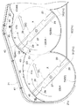
図7は、モーア20の横他端部(刈り草排出口23が位置する側の横端部)での横断平面図である。この図に示すように、前バッフルプレート40の前記排出側プレート部44は、前記回転域22CAの前方に中央刈り刃22Cの回転軸芯Xに対して刈り草排出口23が位置する側に寄せて配置した屈曲点48を備えている。この屈曲点48は、排出側プレート部44を中央刈り刃用プレート部42と最排出口側刈り刃用プレート部43との間で刈り刃ハウジング前後方向に屈曲させている屈曲点である。排出側プレート部44の前記屈曲点48よりも流動案内方向での下手側に位置する下手側プレート部分としての最排出側刈り刃用プレート部43を、この最排出側刈り刃用プレート部43の流動案内終点43aと前記屈曲点48とを通る直線Lよりも刈り刃ハウジング前方側に配置してある。
これにより、排出側プレート部44は、回転域22CAと22RAの間と、その付近とにわたって適切な広さの合流空間を形成し、かつ、この合流空間と刈り草排出口23との間に適切な広さの風流路を形成し、中央刈り刃22Cからの風と最排出口側刈り刃22Rからの風とが前記合流空間で合流し、前記風流路を最排出口側刈り刃用プレート部43に案内されて刈り草排出口23に流動する際、前記合流空間や前記風流路に速度が速いあるいは強い空気流れや刈り刃ハウジング下方向き風を発生しにくくしている。
FIG. 7 is a cross-sectional plan view of the mower 20 at the other lateral end (the lateral end on the side where the cut grass discharge port 23 is located). As shown in this figure, the discharge side plate portion 44 of the front baffle plate 40 is moved toward the side where the cut grass discharge port 23 is located with respect to the rotation axis X of the central cutting blade 22C in front of the rotation area 22CA. The bending point 48 is arranged. The bending point 48 is a bending point at which the discharge side plate portion 44 is bent in the longitudinal direction of the cutting blade housing between the central cutting blade plate portion 42 and the most discharge port side cutting blade plate portion 43. The plate portion 43 for the most discharge side cutting blade as the lower side plate portion located on the lower side in the flow guide direction from the bending point 48 of the discharge side plate portion 44 is used as the plate portion 43 for the most discharge side cutting blade. It is arranged on the front side of the cutting blade housing with respect to a straight line L passing through the flow guide end point 43a and the bending point 48.
As a result, the discharge side plate portion 44 forms a confluence space having an appropriate width between the rotation areas 22CA and 22RA and the vicinity thereof, and is suitable between the confluence space and the cut grass discharge port 23. A wind passage having a wide width is formed, and the wind from the central cutting blade 22C and the wind from the most discharge port side cutting blade 22R merge in the merging space, and the wind passage is connected to the plate portion for the most discharge port side cutting blade. When the air flows into the cut grass outlet 23 while being guided by 43, it is difficult to generate a high-speed or strong air flow or wind toward the cutting blade housing downward in the merge space or the wind passage.

後バッフルプレート50は、前記最上手刈り刃22Lに対応した最上手刈り刃対応部51と、前記中央刈り刃22Cに対応した前記中央刈り刃対応部52と、前記最排出口側刈り刃22Rに対応した最排出口側刈り刃対応部53とを備えている。前記最上手刈り刃対応部51は、刈り刃ハウジング上下方向視で最上手刈り刃22Lの回転域22LAに沿った円弧形になっている。この最上手刈り刃対応部51の一部は、前記円弧形端部壁31によって構成してある。前記中央刈り刃対応部52は、刈り刃ハウジング上下方向視で中央刈り刃22Cの回転域22CAに沿った円弧形になっている。前記最排出口側刈り刃対応部53は、刈り刃ハウジング上下方向視で最排出口側刈り刃22Rの回転域22RAに沿った円弧形になっている。この最排出口側刈り刃対応部53の一部は、前記円弧形端部壁31によって構成してある。   The rear baffle plate 50 is connected to the uppermost hand cutting blade corresponding portion 51 corresponding to the uppermost hand cutting blade 22L, the central cutting blade corresponding portion 52 corresponding to the central cutting blade 22C, and the most discharge port side cutting blade 22R. A corresponding discharge port side cutting blade corresponding portion 53 is provided. The uppermost hand cutting blade-corresponding portion 51 has an arc shape along the rotation area 22LA of the uppermost hand cutting blade 22L as viewed in the vertical direction of the cutting blade housing. A part of the uppermost hand cutting blade corresponding part 51 is constituted by the arc-shaped end wall 31. The central cutting blade corresponding portion 52 has an arc shape along the rotation area 22CA of the central cutting blade 22C as viewed in the vertical direction of the cutting blade housing. The most discharge port side cutting blade corresponding portion 53 has an arc shape along the rotation area 22RA of the most discharge port side cutting blade 22R as viewed in the vertical direction of the cutting blade housing. A part of the most discharge port side cutting blade corresponding portion 53 is constituted by the arc-shaped end wall 31.

つまり、エンジン5からの駆動力を回転軸11によって刈り刃駆動機構20Dに伝達し、この刈り刃駆動機構20Dによって各刈り刃駆動軸27を駆動することにより、各回転刈り刃22L,22R,22Cを刈り刃駆動軸27が有する刈り刃ハウジング上下向きの軸芯Xまわりで図3に示す回転方向Aに駆動する。すると、最上手刈り刃22Lと最排出口側刈り刃22Rとは、起風羽根29の起風作用により、刈り刃ハウジング21の外部の空気を刈り刃ハウジング21の前縦壁21b、横縦壁21d、後縦壁21cの下方から回転域22LA,22RAに導入して空気流を発生させ、芝、草を空気流によって起立させながら切断刃28によって切断処理する。中央刈り刃22Cは、起風羽根29の起風作用により、刈り刃ハウジング21の外部の空気を刈り刃ハウジング21の前縦壁21bの下方から、さらに後縦壁21cの下方と通気口33と各第二通気口34とから後バッフルプレート50の下方を通してそれぞれ回転域22CAに導入して空気流を発生させ、芝、草を空気流によって起立させながら切断刃28によって切断処理する。各ゲージ輪25が地面に接地して刈り刃ハウジング21を接地支持し、各回転刈り刃22L,22R,22Cを設定刈り高さとしての設定対地高さに維持していることにより、各回転刈り刃22L,22R,22Cによる刈り高さが設定刈り高さになる。各回転刈り刃22L,22R,22Cによって切断処理された刈り草を各回転刈り刃22L,22R,22Cの起風羽根29によって発生した風により、後バッフルプレート50と前バッフルプレート40とに案内させて刈り刃ハウジング21の内部を刈り草排出口23が位置する横一端側に搬送し、刈り草排出口23から刈り刃ハウジング21の横外側に放出する。   That is, the driving force from the engine 5 is transmitted to the cutting blade drive mechanism 20D by the rotary shaft 11, and each cutting blade drive shaft 27 is driven by this cutting blade drive mechanism 20D, whereby each rotary cutting blade 22L, 22R, 22C. Is driven in the rotational direction A shown in FIG. 3 around the vertical axis X of the cutting blade housing of the cutting blade drive shaft 27. Then, the uppermost hand-cutting blade 22L and the most discharge-portion-side cutting blade 22R cause the air outside the cutting blade housing 21 to air out of the cutting blade housing 21 by the wind-up action of the wind-up blades 29. 21d is introduced into the rotation zones 22LA and 22RA from below the rear vertical wall 21c to generate an air flow, and the cutting blade 28 cuts the grass and grass while standing by the air flow. The central cutting blade 22C causes the air outside the cutting blade housing 21 to flow from the lower side of the front vertical wall 21b of the cutting blade housing 21 to the lower side of the rear vertical wall 21c and the air vent 33 by the wind action of the wind blowing blades 29. An air flow is generated from each second vent 34 and below the rear baffle plate 50 through the lower baffle plate 50 to generate an air flow, and the cutting blade 28 cuts the grass and grass while standing by the air flow. Since each gauge ring 25 is grounded to support the cutting blade housing 21 while being grounded, and each rotary cutting blade 22L, 22R, 22C is maintained at a set ground height as a set cutting height, each rotary cutting The cutting height by the blades 22L, 22R, and 22C becomes the set cutting height. The cut grass cut by the rotary cutting blades 22L, 22R, and 22C is guided to the rear baffle plate 50 and the front baffle plate 40 by the wind generated by the wind blades 29 of the rotary cutting blades 22L, 22R, and 22C. The inside of the cutting blade housing 21 is conveyed to the lateral one end where the cut grass discharge port 23 is located, and discharged from the cut grass discharge port 23 to the lateral outside of the cutting blade housing 21.

図3に示すように、モーア20は、刈り刃ハウジング21の刈り刃ハウジング横方向での中央部の前側と後側とに刈り刃ハウジング横方向に並べて設けた一対の接地ローラ61,61,62,62を備えている。   As shown in FIG. 3, the mower 20 includes a pair of grounding rollers 61, 61, 62 provided side by side in the horizontal direction of the cutting blade housing on the front side and the rear side of the central portion of the cutting blade housing 21 in the horizontal direction of the cutting blade housing 21. , 62 are provided.

前側の左右一対の接地ローラ61,61は、刈り刃ハウジング21の前縦壁21bに連結された左右一対の支持部材63に支軸64を介して遊転自在に支持されている。前側の左右一対の接地ローラ61,61は、地面に隆起部などの障害物があると、この障害物に乗り上がって刈り刃ハウジング21の前端側を障害物に突っ込まないように接地支持しながら障害物を乗り越えていく。   The pair of left and right grounding rollers 61, 61 on the front side is supported by a pair of left and right support members 63 connected to the front vertical wall 21 b of the cutting blade housing 21 via a support shaft 64 so as to be freely rotatable. When there is an obstacle such as a raised part on the ground, the pair of left and right grounding rollers 61, 61 on the front side are grounded and supported so as not to ride on the obstacle and push the front end side of the cutting blade housing 21 into the obstacle. Get over obstacles.

図3,4,5に示すように、後側の左右一対の接地ローラ62,62は、前記後バッフルプレート50と直線形中間壁部32とにわたって連結された前記左右一対の支持部材60,60の前記通気口33から後方に突出した部位に支軸65を介して遊転自在に支持されている。後側の左右一対の接地ローラ62,62は、地面に隆起部などの障害物があると、この障害物に乗り上がって刈り刃ハウジング21の後端側を障害物に突っ込まないように接地支持しながら障害物を乗り越えていく。この左右一対の接地ローラ62,62は、通気口33の通気障害になりにくいように接地ローラ62の全体が通気口33から後方に突出した配置で支持されている。   As shown in FIGS. 3, 4, and 5, the pair of left and right grounding rollers 62 and 62 on the rear side are connected to the rear baffle plate 50 and the linear intermediate wall 32, and the pair of left and right support members 60 and 60. A portion protruding rearward from the vent hole 33 is supported via a support shaft 65 so as to be freely rotatable. The pair of left and right grounding rollers 62, 62 on the rear side support the ground so that if there is an obstacle such as a raised portion on the ground, the rear end side of the cutting blade housing 21 will not be pushed into the obstacle. While overcoming obstacles. The pair of left and right grounding rollers 62, 62 are supported in an arrangement in which the entire grounding roller 62 protrudes rearward from the air vent 33 so that the air vent 33 does not easily obstruct the airflow.

〔別実施例〕
本発明は、上記実施例の如く3枚の回転刈り刃を備えたモーアの他、2枚の回転刈り刃を備えたモーアにも、4枚以上の回転刈り刃を備えたモーアにも適応できる。従って、中央刈り刃22Cを、最排出側刈り刃に隣り合った隣り刈り刃と呼称する。
[Another Example]
The present invention can be applied not only to a mower having three rotary cutting blades as in the above embodiment, but also to a mower having two rotary cutting blades or a mower having four or more rotary cutting blades. . Accordingly, the central cutting blade 22C is referred to as an adjacent cutting blade adjacent to the most discharge side cutting blade.

乗用型草刈機全体の側面図Side view of the entire riding mower 乗用型草刈機全体の平面図Top view of the entire riding mower モーアの底面図Moor's bottom view モーアの斜視図Mohr's perspective view モーアの縦断側面図Mohr's profile side view モーアの横一端部での横断平面図Cross-sectional plan view at one end of moore モーアの横他端部での横断平面図Cross-sectional plan view at the other side of the mower

符号の説明Explanation of symbols

21 刈り刃ハウジング
22L,22C,22R 回転刈り刃
22LA,22CA,22RA 回転域
40 前バッフルプレート
43 下手側プレート部分
43a 流動案内終点
44 プレート部
48 屈曲点
L 直線
X 軸芯
21 Cutting blade housings 22L, 22C, 22R Rotary cutting blades 22LA, 22CA, 22RA Rotating area 40 Front baffle plate 43 Lower side plate portion 43a Flow guide end point 44 Plate portion 48 Bending point L Straight line X Axis

Claims (2)

刈り刃ハウジングの内部に刈り刃ハウジング横方向に並んで位置するとともに刈り刃ハウジング上下向き軸芯まわりで回転自在な複数の回転刈り刃と、前記刈り刃ハウジングの横一端部に位置した刈り草排出口と、前記各回転刈り刃からの刈り草を前記刈り草排出口に流動案内するよう、前記刈り刃ハウジングの内部の前記各回転刈り刃の回転域の前方に位置した前バッフルプレートとを備えたモーアであって、
前記前バッフルプレートのうち、前記複数の回転刈り刃のうちの前記刈り草排出口に最も近い最排出口側刈り刃の回転域と、前記最排出口側刈り刃に隣り合った隣り刈り刃の回転域との前方に位置するプレート部を、前記隣り刈り刃の回転域の前方に配置した屈曲点で刈り刃ハウジング前後方向に屈曲した屈曲プレート部に構成し、
前記プレート部の前記屈曲点よりも流動案内方向下手側に位置する下手側プレート部分を、この下手側プレート部分の流動案内終点と前記屈曲点とを通る直線よりも刈り刃ハウジング前方側に配置してあるモーア。
A plurality of rotary cutting blades positioned side by side in the horizontal direction of the cutting blade housing inside the cutting blade housing and rotatable about the vertical axis of the cutting blade housing, and a cutting grass drain located at a lateral end of the cutting blade housing. An outlet and a front baffle plate positioned in front of the rotation area of each rotary cutting blade inside the cutting blade housing so as to flow-guide the cut grass from each rotary cutting blade to the cut grass discharge port. Moor,
Of the front baffle plate, of the plurality of rotary cutting blades, the rotation area of the nearest discharge port side cutting blade closest to the cut grass discharge port, and the adjacent cutting blade adjacent to the most discharge port side cutting blade The plate portion located in front of the rotation area is configured as a bent plate portion bent in the front-rear direction of the cutting blade housing at a bending point arranged in front of the rotation area of the adjacent cutting blade,
A lower plate portion located on the lower side of the flow guide direction with respect to the bending point of the plate portion is disposed on the front side of the cutting blade housing with respect to a straight line passing through the flow guide end point of the lower plate portion and the bending point. Moor.
前記屈曲点は、前記隣り刈り刃の回転域のうちの隣り刈り刃の回転軸芯に対して前記刈り草排出口が位置する側に寄って位置している請求項1記載のモーア。   The mower according to claim 1, wherein the bending point is located closer to a side where the cut grass discharge port is located with respect to a rotation axis of the adjacent cutting blade in a rotation area of the adjacent cutting blade.
JP2006256043A 2006-09-21 2006-09-21 Moore Active JP4630252B2 (en)

Priority Applications (2)

Application Number Priority Date Filing Date Title
JP2006256043A JP4630252B2 (en) 2006-09-21 2006-09-21 Moore
US11/726,370 US7437865B2 (en) 2006-09-21 2007-03-21 Mower with baffle

Applications Claiming Priority (1)

Application Number Priority Date Filing Date Title
JP2006256043A JP4630252B2 (en) 2006-09-21 2006-09-21 Moore

Publications (2)

Publication Number Publication Date
JP2008072960A JP2008072960A (en) 2008-04-03
JP4630252B2 true JP4630252B2 (en) 2011-02-09

Family

ID=39345685

Family Applications (1)

Application Number Title Priority Date Filing Date
JP2006256043A Active JP4630252B2 (en) 2006-09-21 2006-09-21 Moore

Country Status (1)

Country Link
JP (1) JP4630252B2 (en)

Families Citing this family (2)

* Cited by examiner, † Cited by third party
Publication number Priority date Publication date Assignee Title
JP5174053B2 (en) * 2010-01-21 2013-04-03 株式会社クボタ Side discharge mower
JP6362841B2 (en) * 2013-09-27 2018-07-25 株式会社クボタ Mower unit

Citations (4)

* Cited by examiner, † Cited by third party
Publication number Priority date Publication date Assignee Title
JPH0614634A (en) * 1992-07-02 1994-01-25 Kubota Corp Mower
JPH08228553A (en) * 1995-02-22 1996-09-10 Kubota Corp Mower
US5845475A (en) * 1995-11-16 1998-12-08 Exmark Mfg. Co., Inc. Lawn mower having flow control baffles and removable mulching baffles
JP2004041060A (en) * 2002-07-10 2004-02-12 Kubota Corp Mower

Patent Citations (4)

* Cited by examiner, † Cited by third party
Publication number Priority date Publication date Assignee Title
JPH0614634A (en) * 1992-07-02 1994-01-25 Kubota Corp Mower
JPH08228553A (en) * 1995-02-22 1996-09-10 Kubota Corp Mower
US5845475A (en) * 1995-11-16 1998-12-08 Exmark Mfg. Co., Inc. Lawn mower having flow control baffles and removable mulching baffles
JP2004041060A (en) * 2002-07-10 2004-02-12 Kubota Corp Mower

Also Published As

Publication number Publication date
JP2008072960A (en) 2008-04-03

Similar Documents

Publication Publication Date Title
JP6042299B2 (en) Moor cutter blade
JP4275088B2 (en) Side discharge mower
US8028508B2 (en) Mower unit
US7437865B2 (en) Mower with baffle
JP3935793B2 (en) Mower
EP3741198B1 (en) Cutter blade for mower
JP4630252B2 (en) Moore
EP3874931B1 (en) Mower deck
JP4769156B2 (en) Moore
JP4791932B2 (en) Moore
JP4769148B2 (en) Moore
US7448194B2 (en) Mower deck with ventilation hole
JP4546911B2 (en) Rear discharge type mowing device
JP4769155B2 (en) Moore
JP2008278820A (en) Rear discharge mower and grass cutter using the rear discharge mower
JP5174053B2 (en) Side discharge mower
JP5022243B2 (en) Moore
JP4826725B2 (en) Riding lawn mower
JP2007124976A (en) Riding lawn mower
JP3951498B2 (en) Rear discharge mower
JP4989178B2 (en) Mower
JP3900738B2 (en) Rear discharge mower mowing grass transfer device
JP2005218315A (en) Tractor for mower

Legal Events

Date Code Title Description
A621 Written request for application examination

Free format text: JAPANESE INTERMEDIATE CODE: A621

Effective date: 20080924

A977 Report on retrieval

Free format text: JAPANESE INTERMEDIATE CODE: A971007

Effective date: 20100827

TRDD Decision of grant or rejection written
A01 Written decision to grant a patent or to grant a registration (utility model)

Free format text: JAPANESE INTERMEDIATE CODE: A01

Effective date: 20101014

A01 Written decision to grant a patent or to grant a registration (utility model)

Free format text: JAPANESE INTERMEDIATE CODE: A01

A61 First payment of annual fees (during grant procedure)

Free format text: JAPANESE INTERMEDIATE CODE: A61

Effective date: 20101112

FPAY Renewal fee payment (event date is renewal date of database)

Free format text: PAYMENT UNTIL: 20131119

Year of fee payment: 3

R150 Certificate of patent or registration of utility model

Ref document number: 4630252

Country of ref document: JP

Free format text: JAPANESE INTERMEDIATE CODE: R150

Free format text: JAPANESE INTERMEDIATE CODE: R150