JP4629028B2 - Adjustable hair holding device - Google Patents
Adjustable hair holding device Download PDFInfo
- Publication number
- JP4629028B2 JP4629028B2 JP2006502943A JP2006502943A JP4629028B2 JP 4629028 B2 JP4629028 B2 JP 4629028B2 JP 2006502943 A JP2006502943 A JP 2006502943A JP 2006502943 A JP2006502943 A JP 2006502943A JP 4629028 B2 JP4629028 B2 JP 4629028B2
- Authority
- JP
- Japan
- Prior art keywords
- hair
- body member
- holding device
- user
- hair holding
- Prior art date
- Legal status (The legal status is an assumption and is not a legal conclusion. Google has not performed a legal analysis and makes no representation as to the accuracy of the status listed.)
- Expired - Fee Related
Links
Images


Classifications
-
- A—HUMAN NECESSITIES
- A45—HAND OR TRAVELLING ARTICLES
- A45D—HAIRDRESSING OR SHAVING EQUIPMENT; EQUIPMENT FOR COSMETICS OR COSMETIC TREATMENTS, e.g. FOR MANICURING OR PEDICURING
- A45D8/00—Hair-holding devices; Accessories therefor
- A45D8/20—Hair clamps, i.e. elastic multi-part clamps, the parts of which are pivotally connected between their ends
- A45D8/22—Hair clamps, i.e. elastic multi-part clamps, the parts of which are pivotally connected between their ends with additional fastener
Abstract
Description
この出願は2003年1月24日提出の米国特許仮出願No.60/442,205、2003年2月4日提出の米国特許仮出願No.60/444,926、2003年5月23日提出の米国特許仮出願No.60/472,953及び2003年7月11日提出の米国特許仮出願No.60/486,485の恩恵を請求する。 This application is a provisional US patent application No. 60 / 442,205 filed on January 24, 2003, a US provisional patent application No. 60 / 444,926 filed on February 4, 2003, and a US patent provisional application filed on May 23, 2003. Claim the benefits of application No. 60 / 472,953 and US provisional application No. 60 / 486,485 filed July 11, 2003.
本発明は第一本体と第二本体が旋回軸上で接続され、ひと集めにした髪の固まりに強く噛み合うように機能する髪保持及び髪スタイリング装置に関する。 The present invention relates to a hair holding and hair styling device in which a first main body and a second main body are connected on a pivot axis and function to strongly mesh with a group of collected hair.
使用時に人の髪を保持する蝶番式バネ押圧装置はこの技術の中で知られている。この種の装置は長年使用されて来ており、初期の例は米国特許No.2,201,719に記述されている。その装置は代表的に髪グリップ、ハンドル部を含む一対の対面した蝶番で組み立った部材により成る。握り部は押圧装置により閉じる部分又は髪つかみ部分に傾き、最もたびたび傾くのは、その部材のハンドル部の閉じる力を働かせるねじりバネである。装置を動作させるために、使用者は押圧手段の押圧力に打ち勝ち、それにより髪保持部を離すために指圧ハンドル部を握る。握り力を維持する間に、使用者はその装置により掴めるように望みの髪の量を対面する髪掴み部に置く。それから、使用者はハンドル部を離し、ねじりバネは髪つかみ部が束ねた髪又は集めたもじゃもじゃの髪をしっかりと接触させる。 Hinged spring pressing devices that hold a person's hair in use are known in the art. This type of device has been in use for many years and an early example is described in US Pat. No. 2,201,719. The device typically comprises a member assembled by a pair of facing hinges including a hair grip and a handle. The grip portion is tilted to the closing portion or the hair grip portion by the pressing device, and the most frequently tilted portion is a torsion spring that applies the closing force of the handle portion of the member. In order to operate the device, the user overcomes the pressing force of the pressing means, thereby grasping the acupressure handle part to release the hair holding part. While maintaining the grip, the user places the desired amount of hair on the facing hair grip so that it can be gripped by the device. Then, the user releases the handle part, and the torsion spring firmly contacts the hair bundled by the hair gripping part or the collected hair.
上記タイプの髪保持装置の欠点は使用者の髪の回りの意図する位置に保持させることの失敗である。付け加えて、バネ押圧保持装置は使用者がその装置の傾きばねにより生成されたねじり力より多少きつく髪を保持するようにその装置を調整させない。言い換えれば、先行技術のバネ押圧髪保持装置の緩さ又はきつさは使用者の制御、すなわち厚さ、きめ、長さ等のような使用者の髪タイプ、及び/又は捻り傾きばねのバネ力またはトルク、を超えた因子により決定される。 A drawback of the above type of hair holding device is the failure to hold it in the intended position around the user's hair. In addition, the spring-pressed holding device does not allow the user to adjust the device to hold the hair somewhat tighter than the torsional force generated by the tilt spring of the device. In other words, the looseness or tightness of the prior art spring-pressed hair holding device is controlled by the user, i.e. the user's hair type such as thickness, texture, length etc. and / or the spring force of the torsion spring. Or it is determined by a factor exceeding the torque.
上記のように髪を固定した後に、握り部をもっときつく固定させる試みとして、その装置の使用者はお互いに内側に向かい髪掴み部をぎゅっと握る。これは留めた髪の一時的な圧力が使用者の望む髪固定位置へ達成させる。しかしながら、握り部材が離されると、圧縮された髪は使用者による瞬間補助的な圧縮に対する膨張力を及ぼす。さらに、膨張する一塊の髪又はもじゃもじゃの髪は髪掴み手段の髪掴み部が傾きバネの捻り力により要求されるように使用者の望む髪固定位置から本来の位置へ後戻りさせる。 In an attempt to fix the grip more tightly after fixing the hair as described above, the users of the device squeeze the hair grip toward each other inward. This allows the temporary pressure of the fastened hair to be achieved to the hair fixing position desired by the user. However, when the gripping member is released, the compressed hair exerts an expansion force on the momentary auxiliary compression by the user. Furthermore, the lump of hair or the hair that is inflated is moved back from the hair fixing position desired by the user to the original position so that the hair gripping portion of the hair gripping means is required by the twisting force of the tilt spring.
押圧手段の押圧力は先行技術の髪保持装置が髪を固定し、そして特定の装置製造者により前もって決定される緩さ又はきつさに直接衝撃を与える。そのような所定の押圧力設定はいくらかの使用者にとって最適かもしれないが他はそうではない。要約すると、先行技術の髪保持装置は使用者がその装置がゆるさ又はきつさを制御及び/又は設定できない。そうする失敗は多くの使用者にその装置の有用性とアピールを減少させる。 The pressing force of the pressing means directly impacts the looseness or tightness that the prior art hair holding device fixes the hair and is predetermined by the particular device manufacturer. Such a predetermined pressing force setting may be optimal for some users, but others are not. In summary, prior art hair holding devices do not allow the user to control and / or set the looseness or tightness of the device. Failure to do so reduces the usefulness and appeal of the device to many users.
ヘヤークリップ及び同等な装置はその技術の中で既知である。しかし、それらは加えられる髪掴み力の範囲の限定もされている。一般的にそれらは普通の閉位置又はせいぜい工場出荷の閉位置を持つ。この所定の位置は使用者の要求及び/又は髪の特性と両立しないので、それらは実用的価値を持たない。たとえば米国特許No.6,082,371の髪保持装置を見てみる。さらに、多数のこれらの装置はその装置の一端で旋回軸で接続される二部材から成る。その蝶番から取り除かれて、その装置の向かい合う端は掛け金、留め金、スナップ、又は同等の留める物、又は閉める物。そのような固定物は使用者の髪に絡みつき、その装置を髪から取外そうとすると使用者の髪や使用者の指を傷つける可能性がある。例として米国特許No.5,196,429, 5,39,691, 5,996,593, 6,089,240, 6,257,249, 6,311,699に記述された髪保持装置を見てみよう。 Hair clips and equivalent devices are known in the art. However, they are also limited in the range of hair gripping force that can be applied. In general, they have a normal closed position or, at best, a factory closed position. Since this predetermined position is incompatible with the user's requirements and / or hair properties, they have no practical value. Take, for example, the hair holding device of US Patent No. 6,082,371. In addition, many of these devices consist of two members connected by a pivot at one end of the device. Removed from the hinge, the opposite ends of the device are latches, clasps, snaps, or similar fasteners or closures. Such fixtures can entangle the user's hair, and attempting to remove the device from the hair can damage the user's hair and the user's fingers. As an example, take the hair holding device described in US Pat. Nos. 5,196,429, 5,39,691, 5,996,593, 6,089,240, 6,257,249, 6,311,699.
したがって、利点はその装置の握り部が使用者の髪掴み部を固定するきつさや緩さの使用者が選択できる調整又は制御を可能にする手段を含む蝶番付き髪保持装置に存在する。 Thus, an advantage resides in a hinged hair holding device that includes means for allowing the user to select tightness or looseness adjustments or controls that allow the grip of the device to secure the user's hair grip.
更なる利点は髪保持装置にあり、使用者の髪の回りにその装置を固定するために装置の蝶番軸から取外される固定物や締め付ける物に貢献する必要性を除去し、それにより使用者の髪に絡みつき、結果として使用者の髪や指を傷つける可能性を減少させる。
先行技術の髪保持装置に対して、本発明の髪保持装置はその装置が本体部材の髪掴み部の間でどのくらいのきつさや緩さで髪を固定するか使用者が影響及び/又は制御できるように設計されている。本発明は使用者に手でそれらの位置で一緒に内側に握られた後で、望まれる髪固定位置に蝶番接続髪掴み部材を留められるように機械的妨害、抵抗、又は摩擦のための方法や手段を与えることにより先行技術の欠点を克服できる。そうすることにより、本発明は髪をもっときつく、そしてより長い期間保つ改良した髪保持装置を提供する。本発明の全ての実施例の中で、各々が髪掴み部、及び、向かい合った本体部材が拡がった位置及び使用者が選択できる髪掴み位置の間で、蝶番軸の回りをお互いに関連して旋回させる蝶番連結手段から成る、向かい合う一対の本体部材からなる髪保持装置が提供される。 In contrast to prior art hair holding devices, the hair holding device of the present invention allows the user to influence and / or control how tight and loose the device fixes the hair between the hair grips of the body member. Designed to be The present invention is a method for mechanical obstruction, resistance, or friction so that the user can hold the hinged hair gripping member in the desired hair-fixing position after being gripped together in their position by hand. The disadvantages of the prior art can be overcome by providing or means. By doing so, the present invention provides an improved hair holding device that keeps the hair tighter and lasts longer. In all embodiments of the present invention, each is associated with each other about the hinge axis between the hair gripping portion and the position at which the opposing body members are expanded and the hair gripping position selectable by the user. There is provided a hair holding device comprising a pair of body members facing each other, the hinge connecting means being pivoted.
本発明によれば、髪掴み部が使用者により手でぎゅっと押される任意の地点(代表的に閉位置)に、髪保持装置の第一と第二部材の髪掴み部が留まることを可能にするように調整手段が提供されるのが好ましく、それにより使用者は滑らないで髪掴み部の間の一纏まりの髪を最適に固定する。調整手段は蝶番により同軸上に配列され、髪掴み部に増加する動作を伝えるように構成されており、掴み部材は集められた髪の回りで閉じているので、使用者は触覚と聴覚で、カチッと言う感じを経験する。又は、閉められる時に髪掴み部になめらかな連続的動作を与えるように構成されてもよい。 According to the present invention, it is possible to allow the first and second hair gripping portions of the hair holding device to remain at an arbitrary point (typically the closed position) where the hair gripping portion is manually pressed by the user. Adjustment means are preferably provided so that the user optimally secures the mass of hair between the hair grips without slipping. The adjustment means are arranged coaxially by a hinge and are configured to transmit an increasing motion to the hair gripping part, and the gripping member is closed around the collected hair, so that the user can feel and sense, Experience a click. Alternatively, it may be configured to give a smooth continuous motion to the hair grip when closed.
髪保持装置の第一、第二本体部材は使用者が髪掴み部を操作する指圧式ハンドル部を含んでも含まなくてよい。そして、捻り又は他の形式のばねは開位置又は閉位置に向かって髪掴み部を押圧するために与えられる。さらにその装置は使用者の髪から髪掴み部を解放する連結解放手段より成る。 The first and second main body members of the hair holding device may or may not include an acupressure handle portion that allows the user to operate the hair gripping portion. A twist or other type of spring is then provided to push the hair grip toward the open or closed position. The device further comprises a connecting and releasing means for releasing the hair grip from the user's hair.
本発明の他の詳細、目的及び利点は発明の前進を実施する望ましく記述される実施例と望ましい方法の以下の記述に従い明確になるであろう。 Other details, objects and advantages of the present invention will become apparent according to the following description of the preferred described embodiments and preferred methods of carrying out the advancement of the invention.
この発明は添付の図面の中の例示のみで好ましい実施例の以下の記述からより明確になる。 The invention will become more apparent from the following description of preferred embodiments by way of example only in the accompanying drawings.
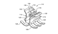
図1で示されているのは蝶番ピン16による旋回軸上に結合した一対の剛性本体部材12と14からなる典型的なバネ押圧保持装置であり、そのピンはその剛性部材により支持される共同接続取っ手18と20を通り抜けている。部材12と14はハンドル部30と32及びそれぞれ複数の噛み合う髪噛み合わせ指又は歯26と28で終止する髪保持装置掴み部22と24より成る。普段はねじりバネ34は蝶番16の回りに露出されている。その技術で既知の通り、ねじりバネは装置10の組立上で圧縮応力が加えられ、両端の突き出しアームは部材12、14が図示された閉位置に来るようにハンドル部30、32に対して力を加える。
Shown in FIG. 1 is a typical spring pressing and holding device comprising a pair of
使用者が装置10を付けたい時、使用者は内側にハンドル部30,32を押し又はひねって、描かれていないが開位置に向かって髪グリップ位置22、24と歯26,28を蝶番で離し髪の房を受ける。使用者がハンドル部30,32を離せば、ねじりバネ34は本体部材12,14を内側に回転させ髪押さえ位置にさせ、そして、使用者の髪を髪掴み位置22,24とその歯26,28の内側に固定させる。
When the user wants to attach the
上述のように、装置10を取り付けた後、使用者はその装置が髪の留めたい場所にしっかり固定されないということをしばしば発見する。したがって、しばしば使用者はお互い内側に向かい掴み部22,24をよりきつく締めようとする。これは使用者が望む髪固定効果を達成するために、髪掴み部とその歯が接近するようにして動かし、その中の掴まれた髪を圧縮する原因となる。しかしながら、髪掴み部22,24が離されると、圧縮された髪は使用者により加えらた髪掴み部の臨時の過圧縮に対抗して膨張力を加える。集められた髪による生み出される膨張力は髪掴み部を使用者が望む髪固定状態から元々の捻られる以前の状態に巻き戻させ、よれにより、その装置は簡単に使用者が望む髪固定位置から取外されるかもしれない。
As described above, after installing the
図2から図5を参照すると、本発明に伴い組立てられた髪保持装置と摩擦型調整機構の第一実施例が見られる。参照番号110により一般的に特定されるその装置は蝶番ピン116により軸方向に接続された一対の剛性本体部材112と114から成り、蝶番ピンはその剛性部材により支持される共同接続接続取っ手118と120を通り抜ける。部材112、114はそれぞれ、ハンドル部130と132、複数の髪噛み合い指又は歯126と128を終結させる髪掴み部122と124から成る。参照番号134は蝶番ピン116の回りに配置される選択的な描かれていないが、ねじりバネを受け入れる隙間を表している。存在する場合、ねじりバネは装置110組立て上で圧縮応力が掛けられ、両端の突き出しアームはハンドル部130、132に対し、描かれた閉位置に部材112,114が来るように力を掛ける。
Referring to FIGS. 2-5, there can be seen a first embodiment of the hair holding device and friction type adjusting mechanism assembled according to the present invention. The device, generally identified by
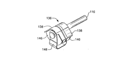
図2,図4と図5の中で参照番号136により概ね特定されるのは、本発明に従う摩擦型調整機構での第一実施例ある。この中で開示された本発明の精神と範囲内の全ての摩擦型調整機構及び同等な物は、関連する髪保持装置の蝶番手段に関して同軸上に配置され、その装置の髪掴み部が使用者により押し込められた位置に留まるように十分な摩擦力を生成する。そのような配列によりいくつかの利点が明白である。注意すべきは、髪保持装置は着用者の髪の上に確かに留まり、絡みにくくすることである。そして、蝶番と同軸上に調整手段を置くことで、小型で美的な組立て品が作り出されるかもしれない。
2, 4 and 5 is generally identified by
摩擦型調整機構136と以下に記述される他の物は「すべり摩擦機構」と呼ばれる。この中で使用されるように、「すべり摩擦機構」はラチェット及びすべり摩擦ディスククラッチ組立ての派生である。以下のように巻き髪やもじゃもじゃの髪について、髪掴み部122、124を漸進的に締めるために使用されるのはラチェットの派生であり、(摩擦クラッチのようでなく、この中で述べられる様々なすべり摩擦機構は事実上消極的であり、すなわち、それらは髪保持装置の全ての部品を操作するのに役立っていないが、)摩擦クラッチに掛けられたトルクが大きすぎる時、クラッチが滑るのと同様な方法で、着用者が髪掴み部122、124を押し込む位置は、調整機構136の摩擦力を越す回転力により打ち負かされる。本発明のすべり摩擦は第一本体部材を伴った第一表面(即ち、本体部材112)、第二部材を伴う第二表面(即ち、第二本体部材114)、及び第一、第二表面間の接触を維持するための押圧手段から成り、それにより、すべり摩擦境界面は第一、第二表面の間で作り出される。すべり摩擦境界面で作り出されるせん断力又は摩擦力は、使用者が滑り摩擦境界面で摩擦力又はせん断力を超す回転開力を掛ける事により、その装置を外すことを選択する時まで、その本体部材を使用者が望む選択された位置に留めさせるのに(ねじりバネ又は他の本体部材押圧装置がそこにあるかどうかに関わらず)全ての例の中で、十分に違いない。
The friction
この中で述べられる全摩擦製造要素は少なくとも一つの表面上の又は表面での摩擦を生成できるに違いない。摩擦を生成する手段は、例えば、荒っぽい表面、手触りの粗い表面、又はギザギザ又は鋸状の表面のような凹凸な表面を含んでも良い。付け加えると、歯状の摩擦生成手段の歯を付ける事は例えば鋸歯の設計のように、角度が同様であり、それにより圧縮した髪を固定するその発明に従う髪保持装置は、更に理想的な髪固定位置を維持することを、他方、使用者による開閉を簡単にする。その上、摩擦手段は髪保持装置本体部材の開閉位置間の回転する円弧に渡り、でたらめ、連続的、後退する又は前進するようなせん断力又は摩擦力を生成するように設計されていても良い。剛性でなく、例えば天然又は人造ゴムやゴムのような構成部品のエラストマーのような生来の摩擦生成特性を持つ摩擦生成要素として、その要素は着用者の髪の周りに髪保持装置をしっかり保持するために十分な摩擦力あるいはせん断力を生成するように適切に選択されても良い。 All friction manufacturing elements described herein must be capable of producing friction on or at least one surface. The means for generating friction may include, for example, rough surfaces, rough textured surfaces, or uneven surfaces such as jagged or serrated surfaces. In addition, attaching the teeth of the tooth-like friction generating means is similar in angle, for example a saw blade design, whereby the hair holding device according to the invention for fixing compressed hair is more ideal hair Maintaining a fixed position, on the other hand, simplifies opening and closing by the user. In addition, the friction means may be designed to generate a shearing or frictional force across the rotating arc between the open and closed positions of the hair holding device body member, such that it is staggered, continuous, retracted or advanced. . As a friction-generating element that is not rigid and has natural friction-generating properties such as natural or man-made rubber or rubber component elastomers, the element holds the hair holding device firmly around the wearer's hair Therefore, it may be appropriately selected to generate sufficient frictional force or shearing force.
更に、この中に記述された本発明の実施例は蝶番に垂直に延びる摩擦境界面で構成されている。しかし、この発明はそれに限定されない。以下の記述のように、すべり摩擦又は非すべり摩擦のどちらかが蝶番手段に平行に延びるということが考えられる。例えば、他の本体部材により支持される円柱取っ手の中で受け入れられる一つの髪保持装置本体部材は(そして、好ましくは蝶番ピンとして働く)蝶番軸と同軸で延びるシャフトを含んでも良い。そのような配列で、シャフトの外側表面と取っ手の内側表面は凹凸な、摩擦の大きい、又は摩擦境界面の達成を妨げる、表面の組合せを持っていても良い。そのような境界面の表面接触力を維持し高めるために、軸又は取っ手は長手方向に割れ、他の軸又は取っ手はスリットの入った部材の上に圧縮応力を加えるように適当なサイズにされ、それにより妨げる部材は摩擦境界面で接触を維持する押圧手段として一緒に機能する。例えば、円柱状の取っ手は長手方向にスリットが入っており、軸は取っ手の穴に関係し、幾分半径方向に大きく、それにより、軸は取っ手の壁を僅かに拡張するように半径方向に外側に向かい膨張力を加える。逆に、軸は長手方向にスリットが入り、取っ手の穴は軸に関係して幾分サイズが小さく、それにより、取っ手はスリットが入った軸を僅かに閉めるために半径方向内側に向かう圧縮力を加える。 Furthermore, the embodiment of the invention described therein is constituted by a friction interface extending perpendicular to the hinge. However, the present invention is not limited to this. As described below, it is conceivable that either sliding friction or non-sliding friction extends parallel to the hinge means. For example, one hair retention device body member received in a cylindrical handle supported by another body member may include a shaft extending coaxially with a hinge axis (and preferably acting as a hinge pin). In such an arrangement, the outer surface of the shaft and the inner surface of the handle may have a combination of surfaces that are uneven, high friction, or impede achievement of the friction interface. In order to maintain and enhance the surface contact force of such interfaces, the shaft or handle is cracked in the longitudinal direction and the other shaft or handle is sized appropriately to apply compressive stress on the slit member. The blocking member thereby functions together as a pressing means to maintain contact at the friction interface. For example, a cylindrical handle has a slit in the longitudinal direction and the shaft is related to the hole in the handle and is somewhat larger in the radial direction, so that the shaft is radially expanded to slightly expand the wall of the handle. Apply expansion force to the outside. Conversely, the shaft has a slit in the longitudinal direction and the hole in the handle is somewhat smaller in size relative to the shaft, so that the handle is compressed radially inward to slightly close the shaft with the slit. Add
図3の拡大図を見ると、すべり摩擦調整機構136はその図に明確に示されたとおり、蝶番ピン115を受け入れる開口部140を持つ少なくとも一つの摩擦生成要素138から成る。摩擦生成要素138は剛性の板又はディスクの形状であり、それの表面144の少なくとも一部に設置された凹凸な表面142の形状の摩擦生成手段を含む。限定するわけではないが、凹凸表面142は歯のついた表面でも良い。凹凸表面は摩擦生成要素138の中に設置され、表面144に取り付けられる別の部材で与えられても良い。更に、髪保持装置それ自身の必須の構成部品から分離した摩擦生成要素は必要ではないとも考えられる。すなわち、蝶番ピン自身又はその装置の共同蝶番ピン受入れ取っ手のセットの片方又は両方は一体化した摩擦生成要素又は表面により与えられ、摩擦生成表面の間の許容差は非常に厳しいかタイトであり、構成要素自身の柔軟性は限られ、お互い接触して摩擦力生成表面を保持する押圧手段として働く。更に又、本発明に従う全ての記述の実施例は、髪保持装置の共同本体部材により支持される共同取っ手で受け入れられる蝶番ピンから成る蝶番手段を示しているが、本体部材はプラスチック材料から適当に選択され、それらの間に柔軟性のある継ぎ手を作り出すプラスチック成形工程の最中にお互いに繋げられ、それらは「生きている蝶番」と一般的に呼ばれる。その場合は、いかなる適当な摩擦生成要素は、それらが生きている蝶番の軸と一緒に同軸で延びている限り、その装置と同時に形成されるか、又は後で取り付けられる。
Turning to the enlarged view of FIG. 3, the sliding
図4、図5を参照すると、すべり摩擦調整機構136はお互い接触している凹凸表面142を持って対面する関係である一対の摩擦精製要素138から好ましくは成るという事が分かる。要素138の接触面部分は第一、第二本体部材112,114に対応する取っ手118、120(図4、図5に図示されていないが)間に望ましくは挿入され、それらの蝶番ピン受入れ開口部は取っ手のそれと一直線になる。選択的にスラスト板又は当て板146は概ねU型金属バネクリップ押圧手段148の脚の軸圧縮力又は推進力を生じる取っ手の向かい合う面に加えられ、凹凸表面142の間で接触を維持する。取っ手と髪保持装置110自身と圧縮接触するバネクリップ148を効果的に維持するために、クリップの向かい合う脚は十分長く、蝶番ピン116を超して伸び、そのピンを受ける一直線に並んだ開口部を含む事が好ましい。
4 and 5, it can be seen that the sliding
使用者が装置110を着用する場合、使用者はハンドル部130、132を一緒に内側にひねり、それにより、髪掴み部122、124と歯126,128を使用者の集めた髪の固まりを受け入れるため描かれていないが開位置に向かい旋回軸上に離す。そして、使用者は髪の固まりに対して望む髪掴み位置で髪掴み部122、124を握る。使用者がそうする時、使用者により加えられた力は、対面する不規則表面142により作り出されるすべり摩擦境界面で生成されるせん断力又は摩擦力に打ち勝つ。このように調整機構136は組立てられ、髪掴み部に徐々に増加する動作を与え、それにより、使用者は掴み部材が集めた髪の回りで閉められる時に、触覚及び/又は聴覚でカチカチという感覚を経験する。または、上記のように、すべり摩擦境界面の一箇所又は両方の接触面で、生来の高摩擦材料(例えば、天然又は人造ゴム又はゴムのような合成品)でなく概して滑らかな材料を使用したすべり摩擦調整機構が使用されても良い。その様に構成され、その調整機構は、それらがお互いに閉められるときに、髪掴み部122,124へ徐々に増加する動作よりむしろ滑らかで連続的動作を与える。どちらの場合も、髪クランプ位置が選択されると、すべり摩擦調整機構は、それらが開き、髪解放位置に達するまで使用者が再びハンドル部130,132を内側に押し付けることによりその装置を取りはずす事を選択するまで、集めた髪の膨張力に対する位置で髪保持装置を維持する。
When the user wears the
図6から図8を参照すると、本発明に従って構成された髪保持装置と摩擦型調整機構の更なる実施例が示されている。その装置は参照番号210で表されているが、蝶番ピン216により枢軸上に接続された一対の剛性本体部材212と214より成り、そのピンはその剛性部材により支持される共同接続取っ手218、220を通り抜ける。部材212、214はそれぞれハンドル部230、232及び複数の噛み合う髪かみ合い指又は歯226、228を終止させる髪掴み部222、224から成る。ねじりバネ234は蝶番ピン216の回りに配置される。この技術で既知の通り、ねじりバネは組立装置210により圧縮応力が加えられ、両端の突き出しアームは部材212、214を図6で描かれた閉位置にさせるようにハンドル部230、232に対して力を加える。使用者は上記に記述された装置110と同様な方法で装置210の取り付け、取り外しを行なう。
Referring to FIGS. 6-8, there is shown a further embodiment of a hair holding device and friction type adjustment mechanism constructed in accordance with the present invention. The device is designated by
図7の参照番号236から概ね特定されるのは、本発明に従う更に現在考えられている実施例である。調整機構236の構造と機能を明確に伝達するために、ある要素は破線や点線で表される。図6から図8に見られるように、接続取っ手218、220は軸方向に細長い。図8は少なくとも一つの細長い一対の取っ手218,220はそれぞれ軸受け218aと220aの位置を決めることを表す。この実施例によると、各軸受け218a、220aは円柱状のインサートの中に組立てた一対の摩擦生成要素の一つを受け入れる。直円柱であるように見られるが、軸受け218a、220a及びインサート238は直線及び/又は曲線状かもしれない。一つのインサート238は図9にて拡大され示される。その図でインサート238は蝶番ピン216を受け入れる開口部240を含んでいる事が分かる。インサート238は少なくとも一つの表面の一部に凹凸表面242の形状である摩擦生成手段を含む。実証として、しかしこれに限定しないが、凹凸表面242は歯のついた表面かもしれない。凹凸表面は摩擦生成要素238の中に作られるか、表面244に別々の部材として与えられるかもしれない。円柱の場合、対応する軸受け218a、220aに関連するそのインサートの回転を防止する手段250を含むことが好ましい。図示の通り、手段250は軸受け218a、220aの内側表面に備えられた一つ以上の対応して作られ配列された突起と噛み合う一つ以上のノッチでもよい。又、ノッチと突起の配置は逆でも良い。更に、インサート238とその関連する軸受け218a、220aは正円柱形状以外であれば、その共同の軸受けに対してインサートの回転を防止する補助的手段を必要としない。
Generally identified from
図7は摩擦生成インサート238の凹凸表面242の間で接触を維持する押圧手段248を表す。この場合、押圧手段248はインサート238と軸受け218aの閉じた端に接する圧縮応力の掛かった状態の圧縮バネである。細長い取っ手218、220と関連する軸受け218a、220aは圧縮バネ248の位置と同じように逆でも良い(すなわち、取っ手218より取っ手220の中に位置してもよい)。同様に、取っ手218と220は圧縮バネ248を含んでも良い。そのうえ、一つの取っ手218又は220は圧縮バネ248とインサート238を含んでも良く、もうひとつの取っ手は凹凸で、摩擦生成をする表面に形成され、与えられる表面と一枚岩であっても良い。
FIG. 7 represents a
この様に更に記述されるように、第一及び第二実施例の間の対比に見られるように、ねじりバネは自由選択である。従来型の髪保持装置のねじりバネは一般的に、理想的にその装置が髪を固定するには力不足であるが、本発明によるどのタイプの調整手段と組み合わせるねじりバネはそれができる。インスタント摩擦型調整手段は一塊の髪又はもじゃもじゃの髪をしっかり固定する髪保持装置を提供するためにねじりバネ又は全てのタイプの押圧手段の補助の力を作り出す。すなわち、摩擦生成手段はその装置の髪掴み手段の間で圧縮される時、髪により加えられる膨張力に打ち勝つために必要な付加的な力を供給する。よりよく髪を固定するために、十分なトルクを持つ力を持ったねじりバネ付きの髪保持装置を作ることは可能であるが、その様な装置は体力的に弱い人には開けられない。そして、やや普通の体力的強さを持つ他の人は、その装置の開閉は使用者の指を酷使させ、それにより、装置の有用性やアピールを減少させる。 As further described in this way, the torsion spring is optional, as seen in the contrast between the first and second embodiments. The torsion springs of conventional hair holding devices are generally insufficient in force for the device to fix the hair, but the torsion springs combined with any type of adjustment means according to the present invention can. The instant friction type adjustment means creates the auxiliary force of a torsion spring or all types of pressing means to provide a hair holding device that secures a mass of hair or shaggy hair. That is, when the friction generating means is compressed between the hair gripping means of the device, it provides the additional force necessary to overcome the expansion force applied by the hair. Although it is possible to make a torsion springed hair holding device with sufficient torque to fix the hair better, such a device cannot be opened by a physically weak person. And, for other people with moderate physical strength, opening and closing the device causes overuse of the user's fingers, thereby reducing the usefulness and appeal of the device.
本発明の髪保持装置は使用者がその装置を開けるのを促進するためのハンドルや他の手段を持っていてもなくてもよい。実際、上記の各々の実施例で、第一と第二本体部材は使用者がその装置を開けることを補助するハンドル部なしで組立てられる。仮にその様な開けるための補助がない場合、その装置の使用者は離す方向に第一部材と第二部材を手で引っ張る、てこで引っ張る等を行なう。しかし、上記に述べたようなハンドル部がない場合、本発明の髪保持装置は下記に述べられるような髪掴み位置からその装置を開けるための連結を解く手段が与えられる。 The hair holding device of the present invention may or may not have a handle or other means to help the user open the device. In fact, in each of the above embodiments, the first and second body members are assembled without a handle that assists the user in opening the device. If there is no such assistance for opening, the user of the apparatus pulls the first member and the second member by hand in the direction of separating, or pulls with a lever. However, in the absence of the handle portion as described above, the hair holding device of the present invention is provided with means for breaking the connection to open the device from the hair gripping position as described below.
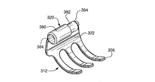
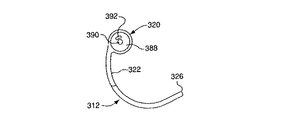
図10と図11を参照すると、それぞれ、全閉、全開位置にある本発明に伴って組立てられた髪保持装置と摩擦型調整機構の更なる実施例が示されている。その装置は参照番号310で示されるが、連結解放装置と摩擦型調整機構(以下に記述する)により旋回軸上に接続される一対の剛性本体部材312と314から成り、それはその剛性部材により支持される接続取っ手318と320を通り抜ける。部材312、314はそれぞれ、髪掴み部322と324から成り、複数のお互いに噛み合う髪噛み合い指326又は歯328で終結する。図10と図11のなかで参照番号360により概ね示されるのは、摩擦型調整機構を解放するように機能する現在考えられている実施例である。装置310の利点はそのバネは髪保持装置が髪を引っ掛けやすく、髪や手を傷つけやすい傾向があるねじりバネ又は他の押圧手段を覆い隠すという点である。
Referring to FIGS. 10 and 11, there are shown further embodiments of the hair holding device and friction type adjustment mechanism assembled with the present invention in the fully closed and fully open positions, respectively. The device is designated by
図12Aから図12Cは髪保持装置310の第一本体部材312を描いた図である。この実施例によれば、取っ手320は第一の比較的大きな直径部380と第二の比較的小さな直径部382を持つ細長い円柱として構成される。部分380と382は第二本体部材314と連結解放機構360と協力する軸受け及び他の開口部を持ち、それらは図13から図17において詳細が述べられる。もっと詳細に述べると、外側の端で、部分380は連結解放手段360(図14から図16)の第一作動装置364の広がったプッシュボタンヘッド362を滑りながら受け入れる第一軸受け384を持つ。第二軸受け386は部分380と部分382の中に備えられ、解放手段360の中央部を受け入れる。壁388は第一と第二軸受け384と386を分ける。図12Bと図12Cに見られるように、壁388は中央開口部390と半径方向に配置された開口部392を含む。図17に描かれているように、中央開口部390は解放手段360の第一作動装置364の軸部を受入れ、半径方向に配列された開口部392は解放手段の引っ張りバネ368の第一端部366を受け入れる。取っ手320の部分382の露出端は上述の種類の中から選択される摩擦生成手段又は表面394で形成されても良い。又は、部分382は取っ手320の部分380の中で受け入れられる摩擦生成インサートとして組立てられる。
12A to 12C are views illustrating the first
図13Aから図13Cにを参照すると、髪保持装置310の第二部材314の構成が見られる。取っ手320の部分380と同様に、取っ手318は解除装置360(図14から図16)の第二作動装置364の拡大されたプッシュボタンヘッドを滑って受け入れる第一軸受け396を持つ。第二軸受け398は(図17の組立て装置)取っ手320の部分382を受け入れる取っ手318の中に備えられる。壁400は第一、第二軸受け396と398を分ける。図13Bと図13Cの様に、壁400は中央開口部402と半径方向に配置された開口部404を含む。図17に見られるように、中央開口部402は解放装置360の第二作動装置364の軸部を受入れ、半径方向配置開口部404は解放装置の引っ張りバネ368の第二端370を受け入れる。壁400の露出内側表面は上述の種類の中から選択される摩擦生成手段又は表面406で形成されても与えられても良い。代替として、取っ手318は軸受け398の中で受け入れられる摩擦生成インサートと一緒に備えられる。図10から図13の髪保持装置組立ての付加的な長所は、装置の押圧手段を完全に包み込む雄雌部材の共同を含めた人工のカバーが提供されるということである。
Referring to FIGS. 13A-13C, the configuration of the
取っ手320の摩擦生成手表面394及び取っ手318の摩擦生成表面406は連結解放装置360によりお互い噛み合う時、高程度のせん断力を生成される。実際、取っ手320の摩擦生成表面394及び取っ手318の表面406は解放装置360を伴って、「非滑り摩擦機構」と言及される摩擦型調整機構136を作り出す。ここで使用される「非滑り摩擦機構」の用語はラチェットと非滑り摩擦ディスククラッチ機構を意味する。一塊の髪又はもじゃもじゃの髪について髪掴み部を積極的に強くするために使用されるラチェットの派生である。そして、非滑りディスククラッチ機構であり、着用者が髪掴み部322、324をぎゅっと押し込む位置は、(摩擦クラッチのようでなく、この中で記述される様々な非滑り摩擦機構は消極的であり、すなわち、髪保持装置の軸又は他の部品を操作しないが、)使用者により加えられる回転力により容易には変更できない。本発明による非滑り摩擦機構は第一本体部材(すなわち、本体部材312)に関連する第一表面、第二部材に関連する第二表面(すなわち、第二本体部材314)及び第一、第二表面間の接触を維持する押圧手段、それにより、非滑り摩擦境界面は第一、第二表面の間で作り出される。非滑り摩擦境界面で生成されるせん断力又は摩擦力は、使用者が以下のように解放手段360を使用し、それらを解放する事によりその装置を取外すことを選択する時まで、使用者により本体部材を選択された髪保持位置に保持させることが全ての事例の中で十分である。
The friction generating
図14から図16を参照すると、連結解放手段360の各作動装置部材364は同形状が好ましい。作動装置部材364は中央軸372の一端に配置された上述の広がったプッシュボタンヘッド362から成る。中央軸372の反対側端部に傾斜表面376を持つ作動装置シャフト374がある。図15で明確であるように、作動装置軸の傾斜した表面は図17に関連して記述されるように、向かい合った作動装置を導く相互的に機能するカム面をお互いに創造するように接触させる。各作動装置部材364はそれぞれの取っ手318、320の中で作動装置部材を保持するための壁388又は400の内側面と噛み合う突起378が備えられる。完全に組み込まれた解放手段360は図16に見られ、作動装置部材364は引っ張りバネ368の中に位置している。装置310の全体組立てとして、引っ張りバネ368の第一、第二端366と370は逆方向に圧縮応力が掛かっており、それによりトルクが引っ張りバネに導入され、髪掴み手段を図11の開位置に動かし、取っ手320と318の摩擦生成表面394と406は図17の様な堅固な接触である。
Referring to FIGS. 14 to 16, each
図17に移ると、使用者の髪の周りの髪掴み部に、完全に組み立った髪保持装置310は見られる。その位置を得るために、使用者は望みのとおり一塊の髪を集め、引っ張りバネ368の圧縮されたトルクに対抗して髪の回りで装置の髪掴み部を押し込む。使用者が装置を離したい時、使用者は只、お互いに向かって内側にプッシュボタンを押し、それにより、作動装置軸374の先端は壁の内側面388と400を押す。使用者がボタン362をぎゅっと押し続けると、取っ手320と318の摩擦生成表面394と406はお互い離れる。摩擦生成表面394と406の間に隙間が存在すると、使用者が髪の回りの髪掴み部322、324を内側にぎゅっと握る時のバネ368に生じるトルクは解放され、装置は図11のような開位置に戻る。
Turning to FIG. 17, a fully assembled
摩擦生成手段394,406の間の非滑り摩擦境界面はそんなに大きくなく、使用者は連結解放手段360が働かない場合、髪掴み部322,324を手動で引き離すか、てこで離すことによりせん断力又は摩擦力に打ち勝つことができない。すなわち、非滑り摩擦境界面は上記の滑り摩擦境界面に比べ開きトルクに対して実質的に大きい抵抗を与え、開きトルクに対する抵抗は使用者が他の援助なしで髪掴み部を装置310を取りはずすことを妨害すべきではない。
The non-slip friction interface between the friction generating means 394 and 406 is not so large, and when the connection release means 360 does not work, the user can pull the hair grips 322 and 324 manually or by using a lever to release the shear force. Or the frictional force cannot be overcome. That is, the non-sliding friction interface provides a substantially greater resistance to opening torque than the sliding friction interface described above, and the resistance to opening torque allows the user to remove the
使用者が使用するのが見苦しい及び/又は難しいと、又、連結解放手段360がその機能を除去すると考えたら、装置310はハンドルを提供されない。それにもかかわらず、装置110はある装着者が美的及び/又は機能的だと感じる場合、ハンドルを所有する。又は、装置310が取っ手320と318の摩擦生成表面394と406の間の非滑り摩擦境界面よりむしろ滑り摩擦境界面を持って与えられ、及び/又は連結解放手段360がない場合、ハンドルがあるのが望ましい。
If it is unsightly and / or difficult for the user to use, and the coupling release means 360 considers that function removed, the
本発明は前述のこの技術の中でよく知られている(あごクリップ、つめクリップ、蝶クリップ、ヘアクリップ、及びバナナクリップに限定しないが)その様な装置と同じように米国特許No.2,210,719, 5,396,912, 5,996,593, 6,082,371, 6,089,240, 6,257,249, 6,311,699の中で記述された物に限定しないが、それを含む髪保持装置の領域に適用する方法と手段を提供する。 The present invention is well known in the art described above (but is not limited to chin clips, pawl clips, butterfly clips, hair clips, and banana clips) as well as such a device, U.S. Pat. No. 2,210,719, Although not limited to those described in 5,396,912, 5,996,593, 6,082,371, 6,089,240, 6,257,249, 6,311,699, methods and means are provided for application to areas of hair holding devices including the same.
本発明は例証の目的で細部に渡り記述されているが、その詳細は単にその目的のために過ぎず、その変化はこの中で請求された発明の精神や範囲から逸脱することなく当業者によりなされるという風に理解できる。 Although the present invention has been described in detail for purposes of illustration, the details are merely for the purpose and variations thereof will be apparent to those skilled in the art without departing from the spirit and scope of the invention claimed herein. I can understand that it is made.
Claims (23)
前記第一及び第二本体部材を回転自在に接続する蝶番手段と、
前記髪掴み部を使用者により強く押し込まれた所で前記髪掴み部を留めるために、前記蝶番手段に対して同軸上に配列され、ラチェット及び滑り摩擦ディスククラッチ機構である滑り摩擦機構から成る調整手段と、
より成る髪保持装置。A first main body member and a second main body member comprising a hair grip portion that comes into contact with a lump of hair when the user grips it;
Hinge means for rotatably connecting the first and second body members;
To keep the hair gripping portions where pushed strongly by the user of the hair gripping portions are arranged coaxially with the hinge means consist of sliding friction mechanism is a ratchet and sliding friction disk clutch mechanism Adjusting means;
A hair holding device.
前記第一及び第二本体部材を回転自在に接続する蝶番手段と、
前記髪掴み部を使用者により強く押し込まれた所で前記髪掴み部を留めるために、前記蝶番手段に対して同軸上に配列され、前記押し込まれた所の位置は使用者により加えられる回転力により変更できない、ラチェット及び非滑り摩擦ディスククラッチ機構である非滑り摩擦機構から成る調整手段と、
より成る髪保持装置。A first main body member and a second main body member comprising a hair grip portion that comes into contact with a lump of hair when the user grips it;
Hinge means for rotatably connecting the first and second body members;
To keep the hair gripping portions where pushed strongly by the user of the hair gripping portions rotation, is arranged coaxially with the hinge means, the position of the pushed-in place is exerted by the user An adjustment means comprising a ratchet and a non-sliding friction disc clutch mechanism that cannot be changed by force ;
A hair holding device.
前記第一及び第二本体部材を回転自在に接続する蝶番手段と、Hinge means for rotatably connecting the first and second body members;
前記髪掴み部を使用者により強く押し込まれた所で前記髪掴み部を留めるために、前記蝶番手段に対して同軸上に配列され、前記押し込まれた所の位置は使用者により加えられる回転力により変更できず、互いに離れ間に隙間が存在するときのみ変更できる、ラチェット及び非滑り摩擦ディスククラッチ機構である非滑り摩擦機構から成る調整手段と、In order to hold the hair grip portion when the hair grip portion is strongly pressed by the user, the hair grip portion is arranged coaxially with respect to the hinge means, and the position of the pressed portion is a rotational force applied by the user. The adjusting means comprising a ratchet and a non-sliding friction mechanism that is a non-sliding friction disc clutch mechanism, which cannot be changed by the above-mentioned, and can be changed only when there is a gap between them.
より成る髪保持装置。A hair holding device.
Applications Claiming Priority (5)
| Application Number | Priority Date | Filing Date | Title |
|---|---|---|---|
| US44220503P | 2003-01-24 | 2003-01-24 | |
| US44492603P | 2003-02-04 | 2003-02-04 | |
| US47295303P | 2003-05-23 | 2003-05-23 | |
| US48648503P | 2003-07-11 | 2003-07-11 | |
| PCT/US2004/001761 WO2004066777A2 (en) | 2003-01-24 | 2004-01-23 | Adjustable hair holding device |
Publications (3)
| Publication Number | Publication Date |
|---|---|
| JP2006518630A JP2006518630A (en) | 2006-08-17 |
| JP2006518630A5 JP2006518630A5 (en) | 2010-08-19 |
| JP4629028B2 true JP4629028B2 (en) | 2011-02-09 |
Family
ID=32831096
Family Applications (1)
| Application Number | Title | Priority Date | Filing Date |
|---|---|---|---|
| JP2006502943A Expired - Fee Related JP4629028B2 (en) | 2003-01-24 | 2004-01-23 | Adjustable hair holding device |
Country Status (15)
| Country | Link |
|---|---|
| US (3) | US7493903B2 (en) |
| EP (1) | EP1605792B1 (en) |
| JP (1) | JP4629028B2 (en) |
| KR (1) | KR100839245B1 (en) |
| AT (1) | ATE463970T1 (en) |
| AU (1) | AU2004207510B2 (en) |
| BR (1) | BRPI0406711A (en) |
| CA (1) | CA2513659C (en) |
| DE (1) | DE602004026562D1 (en) |
| DK (1) | DK1605792T3 (en) |
| ES (1) | ES2343522T3 (en) |
| HK (1) | HK1086461A1 (en) |
| MX (1) | MXPA05007859A (en) |
| PT (1) | PT1605792E (en) |
| WO (1) | WO2004066777A2 (en) |
Families Citing this family (24)
| Publication number | Priority date | Publication date | Assignee | Title |
|---|---|---|---|---|
| WO2006015342A1 (en) * | 2004-07-29 | 2006-02-09 | Conair Corporation | Non-slip layer for hair accessories |
| US7753058B2 (en) * | 2004-11-16 | 2010-07-13 | Goody Products, Inc. | Hair retaining clip with elastic biasing member |
| US7992579B2 (en) * | 2006-12-29 | 2011-08-09 | Goody Products Inc. | Hair clip with latch mechanism |
| TWI324508B (en) | 2007-04-18 | 2010-05-11 | Tsorng Ta Entpr Co Ltd | Bobby pin |
| WO2009134761A1 (en) * | 2008-04-30 | 2009-11-05 | Goody Products, Inc. | Hair clip with concealed hinge spring |
| US8216258B2 (en) * | 2009-02-27 | 2012-07-10 | Ted Robert Skipper | Medical clamp and method of use |
| US8082930B2 (en) * | 2009-06-26 | 2011-12-27 | Shih Ling Hsu | Hair clip with tines extending parallel to the enveloped hair |
| US20110030719A1 (en) * | 2009-08-04 | 2011-02-10 | Che-Hsi Yang | Hair clip |
| US20110041867A1 (en) * | 2009-08-21 | 2011-02-24 | Shih Ling Hsu | Hair styling device |
| KR101117029B1 (en) * | 2011-03-03 | 2012-03-16 | 강효종 | Hair clip having elastic band spring covered by closed hinge parts |
| KR101302918B1 (en) * | 2012-05-29 | 2013-09-06 | 김범진 | Hinge structure for small size tongs |
| US9072355B1 (en) | 2013-05-30 | 2015-07-07 | Nicole Irene Magnani | Sharable hair accessory |
| USD736075S1 (en) | 2013-07-08 | 2015-08-11 | Target Brands, Inc. | Ornament attachment clip |
| US9237820B2 (en) | 2013-07-08 | 2016-01-19 | Target Brands, Inc. | Ornament assembly with attachment clip |
| USD771870S1 (en) * | 2015-05-07 | 2016-11-15 | Kai-Mou Tsai | Claw |
| USD776346S1 (en) | 2015-06-01 | 2017-01-10 | Nicole Irene Magnani | Multi-part joinable clip |
| US10051937B1 (en) * | 2016-05-17 | 2018-08-21 | Charlotte Wenzel | Spring-loaded hair clip |
| USD814112S1 (en) * | 2017-03-04 | 2018-03-27 | Shih-Ling Hsu | Hair clip |
| USD829990S1 (en) * | 2017-03-04 | 2018-10-02 | Shih-Ling Hsu | Hair clip |
| USD831273S1 (en) * | 2017-04-06 | 2018-10-16 | Tung Hing Plastic Manufactory Ltd. | Hair clip |
| USD889953S1 (en) | 2017-08-14 | 2020-07-14 | Target Brands, Inc. | Ornament attachment cup |
| US11571055B2 (en) * | 2019-03-15 | 2023-02-07 | Tsorng Ta Enierprise Co., Ltd. | Hair claw clip |
| US11647821B2 (en) * | 2019-07-23 | 2023-05-16 | Durham Enterprises Corporation | Locking clip for hair |
| TWI808491B (en) * | 2021-09-17 | 2023-07-11 | 琮大興業有限公司 | Elastic opening clamp |
Family Cites Families (33)
| Publication number | Priority date | Publication date | Assignee | Title |
|---|---|---|---|---|
| US870330A (en) * | 1907-06-28 | 1907-11-05 | Attleboro Mfg Company | Ear-ring. |
| US1765880A (en) * | 1928-04-10 | 1930-06-24 | Firm M Vogel A G Geschaftsbuch | Clamping device for files, newspaper holders, and the like |
| US2008382A (en) * | 1934-08-30 | 1935-07-16 | Thomas S Bennett | Attaching means for ear ornaments |
| US2201719A (en) | 1939-08-17 | 1940-05-21 | Eicher Pearl | Curl clip |
| US2405025A (en) * | 1944-01-29 | 1946-07-30 | Feingold Lipa | Earring clasp |
| US2947054A (en) * | 1958-05-07 | 1960-08-02 | Apex Jewelry Co | Earring clamp |
| US3546750A (en) * | 1968-10-25 | 1970-12-15 | Robert K Sheehan | Fastener |
| JPS60129289U (en) * | 1984-02-10 | 1985-08-30 | キンシ化学工業株式会社 | Futon scissors with opening adjustment mechanism |
| JPH0346912U (en) * | 1989-09-12 | 1991-04-30 | ||
| US4999937A (en) | 1989-11-13 | 1991-03-19 | Joseph Bechtold | Panel sign having ratchet hinge means |
| US5170644A (en) * | 1991-12-06 | 1992-12-15 | Calabro Anthony S | Adjustable pressure ear clip |
| US5165429A (en) | 1992-01-23 | 1992-11-24 | Miller Victoria A | Hair clamp apparatus |
| US5396912A (en) | 1993-11-30 | 1995-03-14 | Chou; Kuo H. | Structure of barrette |
| US5549127A (en) * | 1995-05-03 | 1996-08-27 | Chang; Wen-Hsiung | Spring fixing structure for a hairgrip |
| US5609169A (en) * | 1995-12-18 | 1997-03-11 | Yang; I-Chien | Hair clip |
| US5842485A (en) * | 1996-03-07 | 1998-12-01 | C.S.P. Diffusion, Societe Anonyme | Curved toothed hairclip |
| US5651167A (en) * | 1996-07-18 | 1997-07-29 | Jovanovich; Radomir M. | Side-actuated clip |
| CA2275343C (en) * | 1996-12-16 | 2003-10-21 | C.S.P. Diffusion | Spring articulation for hair-grip |
| JP3121285B2 (en) * | 1997-04-07 | 2000-12-25 | 株式会社ヤスダコーポレーション | Hair stopper |
| US5799371A (en) | 1997-05-20 | 1998-09-01 | Tamarack Technologies Inc. | Pivoting joint |
| US5996593A (en) | 1997-07-16 | 1999-12-07 | Horman; Heidi Christine | Hair clip |
| US5873377A (en) * | 1998-07-15 | 1999-02-23 | Yang; Che-Hsi | Hair clip improvement |
| US6257249B1 (en) | 1998-07-31 | 2001-07-10 | Samuel L. Thomas | Hair clamp |
| US6082371A (en) * | 1998-09-02 | 2000-07-04 | Geraldine Rose Bader-Saltzman | Hair clip having a novel gripping mechanism and removable decorative attachments |
| US6089240A (en) | 1998-12-21 | 2000-07-18 | Chang; Wen-Hsivng | Hair grip device |
| US6357152B1 (en) * | 1999-04-19 | 2002-03-19 | Debbie S. Brooks | Animated display system and method of fabricating same |
| US6032680A (en) | 1999-04-20 | 2000-03-07 | Lu; Chee-Yin | Hair clip retainer |
| US6263543B1 (en) | 1999-07-30 | 2001-07-24 | Avaya Technology Corp. | Self-latching hinge design |
| US6311699B1 (en) | 1999-12-02 | 2001-11-06 | Remedies Trading Corporation | Ponytail holder |
| FR2802785B1 (en) | 1999-12-28 | 2002-03-22 | Delsol Ets | MASK SPRING HAIR CLIP |
| KR100419927B1 (en) | 2000-03-03 | 2004-02-25 | 산요덴키가부시키가이샤 | Folder type portable phone |
| US6477732B1 (en) * | 2000-04-14 | 2002-11-12 | Kevin W. Cline | Folding bristle hairbrush |
| US7174902B2 (en) * | 2001-01-26 | 2007-02-13 | Conair Corporation | Hair ornament with a resilient attaching clip |
-
2004
- 2004-01-23 CA CA2513659A patent/CA2513659C/en not_active Expired - Fee Related
- 2004-01-23 MX MXPA05007859A patent/MXPA05007859A/en active IP Right Grant
- 2004-01-23 AU AU2004207510A patent/AU2004207510B2/en not_active Ceased
- 2004-01-23 DK DK04704835.0T patent/DK1605792T3/en active
- 2004-01-23 BR BRPI0406711-8A patent/BRPI0406711A/en not_active IP Right Cessation
- 2004-01-23 WO PCT/US2004/001761 patent/WO2004066777A2/en active Application Filing
- 2004-01-23 PT PT04704835T patent/PT1605792E/en unknown
- 2004-01-23 US US10/763,846 patent/US7493903B2/en not_active Expired - Fee Related
- 2004-01-23 EP EP04704835A patent/EP1605792B1/en not_active Expired - Lifetime
- 2004-01-23 DE DE602004026562T patent/DE602004026562D1/en not_active Expired - Lifetime
- 2004-01-23 ES ES04704835T patent/ES2343522T3/en not_active Expired - Lifetime
- 2004-01-23 AT AT04704835T patent/ATE463970T1/en active
- 2004-01-23 US US10/763,447 patent/US20040177860A1/en not_active Abandoned
- 2004-01-23 JP JP2006502943A patent/JP4629028B2/en not_active Expired - Fee Related
- 2004-01-23 US US10/764,237 patent/US7950401B2/en not_active Expired - Fee Related
- 2004-01-23 KR KR1020057013308A patent/KR100839245B1/en not_active IP Right Cessation
-
2006
- 2006-06-08 HK HK06106604.9A patent/HK1086461A1/en not_active IP Right Cessation
Also Published As
| Publication number | Publication date |
|---|---|
| AU2004207510B2 (en) | 2008-12-18 |
| US7950401B2 (en) | 2011-05-31 |
| ES2343522T3 (en) | 2010-08-03 |
| JP2006518630A (en) | 2006-08-17 |
| KR100839245B1 (en) | 2008-06-17 |
| EP1605792B1 (en) | 2010-04-14 |
| AU2004207510A1 (en) | 2004-08-12 |
| US20040182411A1 (en) | 2004-09-23 |
| WO2004066777A3 (en) | 2006-03-09 |
| EP1605792A4 (en) | 2008-12-10 |
| CA2513659A1 (en) | 2004-08-12 |
| CA2513659C (en) | 2012-05-15 |
| MXPA05007859A (en) | 2006-04-07 |
| US20040177861A1 (en) | 2004-09-16 |
| HK1086461A1 (en) | 2006-09-22 |
| EP1605792A2 (en) | 2005-12-21 |
| PT1605792E (en) | 2010-07-09 |
| DK1605792T3 (en) | 2010-07-26 |
| ATE463970T1 (en) | 2010-04-15 |
| BRPI0406711A (en) | 2007-04-03 |
| KR20050105174A (en) | 2005-11-03 |
| US20040177860A1 (en) | 2004-09-16 |
| DE602004026562D1 (en) | 2010-05-27 |
| WO2004066777A2 (en) | 2004-08-12 |
| US7493903B2 (en) | 2009-02-24 |
Similar Documents
| Publication | Publication Date | Title |
|---|---|---|
| JP4629028B2 (en) | Adjustable hair holding device | |
| US7341295B1 (en) | Prehensor device and improvements of same | |
| US20070131238A1 (en) | Hair retaining clip with elastic biasing member | |
| US8307835B2 (en) | Daisy chain hair clasps for creating ringlets and waves | |
| TW200824601A (en) | Hair clip | |
| JP4616329B2 (en) | Hair stopper | |
| US6319175B1 (en) | Grip device | |
| US5456272A (en) | Hair braiding device | |
| US6257249B1 (en) | Hair clamp | |
| US20030000542A1 (en) | Spiral curling iron device | |
| KR101502886B1 (en) | Hair cutting scissors with improved cutting function | |
| JP3976281B1 (en) | Barrette | |
| WO2006102995A1 (en) | Hair shaping device | |
| TWM263877U (en) | Non-rope window curtain controller | |
| KR200474318Y1 (en) | Pincers for Extention Hair | |
| JP2003259910A (en) | Eyelash curler | |
| KR20190002174U (en) | twin hair roll clip | |
| JP3156237U (en) | Hair clip | |
| JP3069464U (en) | Free pressing position type self-acupressure device | |
| KR200428502Y1 (en) | hairpin | |
| JP2019122601A (en) | Barrette tool | |
| TW200843910A (en) | A torsion sleeve connecting device | |
| TW200307521A (en) | Eyelash shaping machine | |
| KR20070096675A (en) | A hairpin | |
| KR20160021568A (en) | Tongs-shaped pin including auxiliary body |
Legal Events
| Date | Code | Title | Description |
|---|---|---|---|
| A621 | Written request for application examination |
Free format text: JAPANESE INTERMEDIATE CODE: A621 Effective date: 20070117 |
|
| A131 | Notification of reasons for refusal |
Free format text: JAPANESE INTERMEDIATE CODE: A131 Effective date: 20091201 |
|
| A524 | Written submission of copy of amendment under article 19 pct |
Free format text: JAPANESE INTERMEDIATE CODE: A524 Effective date: 20100301 |
|
| A131 | Notification of reasons for refusal |
Free format text: JAPANESE INTERMEDIATE CODE: A131 Effective date: 20100406 |
|
| A524 | Written submission of copy of amendment under article 19 pct |
Free format text: JAPANESE INTERMEDIATE CODE: A524 Effective date: 20100702 |
|
| TRDD | Decision of grant or rejection written | ||
| A01 | Written decision to grant a patent or to grant a registration (utility model) |
Free format text: JAPANESE INTERMEDIATE CODE: A01 Effective date: 20101019 |
|
| A01 | Written decision to grant a patent or to grant a registration (utility model) |
Free format text: JAPANESE INTERMEDIATE CODE: A01 |
|
| A61 | First payment of annual fees (during grant procedure) |
Free format text: JAPANESE INTERMEDIATE CODE: A61 Effective date: 20101110 |
|
| FPAY | Renewal fee payment (event date is renewal date of database) |
Free format text: PAYMENT UNTIL: 20131119 Year of fee payment: 3 |
|
| R150 | Certificate of patent or registration of utility model |
Free format text: JAPANESE INTERMEDIATE CODE: R150 |
|
| R250 | Receipt of annual fees |
Free format text: JAPANESE INTERMEDIATE CODE: R250 |
|
| LAPS | Cancellation because of no payment of annual fees |