JP4628516B2 - Collimator lens and optical scanning device using the same - Google Patents
Collimator lens and optical scanning device using the same Download PDFInfo
- Publication number
- JP4628516B2 JP4628516B2 JP2000090590A JP2000090590A JP4628516B2 JP 4628516 B2 JP4628516 B2 JP 4628516B2 JP 2000090590 A JP2000090590 A JP 2000090590A JP 2000090590 A JP2000090590 A JP 2000090590A JP 4628516 B2 JP4628516 B2 JP 4628516B2
- Authority
- JP
- Japan
- Prior art keywords
- lens
- collimator lens
- refractive power
- focal length
- optical scanning
- Prior art date
- Legal status (The legal status is an assumption and is not a legal conclusion. Google has not performed a legal analysis and makes no representation as to the accuracy of the status listed.)
- Expired - Fee Related
Links
Images


Description
【0001】
【発明の属する技術分野】
本発明は、レーザビームを走査して画像の記録や表示を行うための複写機あるいはレーザプリンタ等の光走査装置に用いられるコリメータレンズに関し、詳しくは半導体レーザ等の光源から射出された発散光束を平行光束に変換するためのコリメータレンズおよびこれを用いた光走査装置に関するものである。
【0002】
【従来の技術】
従来より、レーザビームを走査して画像の記録や表示を行うための複写機あるいはレーザプリンタ等の光走査装置が種々知られている。
このような光走査装置は、半導体レーザから射出されたレーザビームを、コリメータレンズによって平行光束に変換し、回転多面鏡の回転に応じて偏向し、これをfθレンズによって結像面上に結像するように構成されたものである。
【0003】
ところで、一般に用いられるコリメータレンズは、主に軸上性能を満足させることが要求されるため、例えば特開昭61−173214号公報や特開昭61−147225号公報に記載されているように、2枚ないし3枚のレンズで構成されたものが多く知られている。
また、レンズ枚数を多くしたコリメータレンズとして、特開昭61−173215号公報に開示された4〜6枚のレンズ構成のものが知られている。
【0004】
【発明が解決しようとする課題】
しかしながら、上述した特開昭61−173214号公報や特開昭61−147225号公報に記載されている2枚ないし3枚のレンズで構成されたコリメータレンズにおける軸外性能は、正弦条件が満足される極めて狭い範囲においてのみ適応しうるものであり、特に、走査速度の高速化、あるいは一度の走査で異なる複数情報の同時記録を目的としてなされるマルチビーム方式を採用する場合等においては、半画角ωが3度程度となる範囲で、例えば焦点距離25mmで使用した時に像面湾曲を十数ミクロン以内に収めなければならないことから、上記公報記載のコリメータレンズの適用は困難である。
【0005】
また、特開昭61−173215号公報に開示された4〜6枚のレンズで構成されたコリメータレンズは、最も平行光束側に負のレンズを配置した、いわゆるレトロフォーカスタイプのレンズであり、像面湾曲を積極的に少なくするための構成は有しておらず、実際に、実施例に記載されたレンズの像面湾曲量は、上記課題を解決しうる満足な値とはなっていない。
【0006】
さらに、この公報に記載されたコリメータレンズでは、コリメータレンズが光源(レーザーダイオード等)の近くに配置されることとなるため、光源からの熱によりコリメータレンズの温度が上昇し、波面収差が大きくなる等の問題点があった。
【0007】
本発明は、上述した事情に鑑みなされたもので、マルチビーム走査を行う場合に、複数の光源からの各光ビームに対して諸収差、特に像面湾曲量を極めて小さくすることができ、かつ光源からの熱の影響を小さくするために十分なバックフォーカスの確保を可能とした、光走査装置に用いられるコリメータレンズを提供することを目的とするものである。
【0008】
【課題を解決するための手段】
本発明に係るコリメータレンズは、上述した目的を達成するため、平行光束側から順に、正の屈折力を有する第1レンズと、いずれか一方が負の屈折力を有し、他方が正の屈折力を有するレンズからなり、合成で負の屈折力を有する第2レンズおよび第3レンズと、正の屈折力を有する第4レンズを配設するとともに、前記第2レンズおよび第3レンズを接合してなり、かつ下記条件式(1)を満足するように構成してなることを特徴とするものである。
Bf/f>0.8 ・・・ (1)
ここで、
Bf:レンズ全系のバックフォーカス
f :レンズ全系の焦点距離
【0009】
また、前記第1レンズは、両凸レンズであり、前記第4レンズは、光源側の面が凸面である正レンズであり、かつ下記条件式(2)および(3)を満足するように構成してなることが好ましい。
1.0<f1/f<1.5 ・・・ (2)
1.1<f4/f<1.7 ・・・ (3)
ここで、
f1 :第1レンズの焦点距離
f4 :第4レンズの焦点距離
f :レンズ全系の焦点距離
【0010】
また、本発明に係る光走査装置は、上述したコリメータレンズを用いたことを特徴とするものである。
【0011】
【発明の実施の形態】
以下、図面を参照しつつ、本発明の実施形態に係るコリメータレンズおよび光走査装置を実施例1、2を用いて説明する。
【0012】
図1は本発明の実施形態(実施例1に対応させたものを代表的に示す)に係るコリメータレンズのレンズ基本構成図、図6は図1に示すコリメータレンズを用いた光走査装置の概略構成図である。
【0013】
本発明に係るコリメータレンズは、光源から射出されたレーザビームを走査して画像の記録や表示を行うためのレーザプリンタ、コピー機等の光走査装置の光学系に用いられるものである。
【0014】
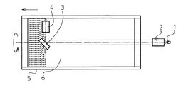
この光走査装置は、図6に示すように、2光源搭載型のワンチップ半導体レーザ等からなる光源1から射出されたレーザビームを平行光束に変換するためのコリメータレンズ2と、内面に感材6を配置するとともにコリメータレンズ2の光軸を回転軸として回転する円筒5を備えており、円筒5内には、コリメータレンズ2により変換された光束を反射するためのミラー3と、ミラー3により反射された光束を円筒5の内面に向かって導くための集光レンズ4とを配設している。なお、図6において、円筒5は、コリメータレンズ2の光軸を含む面における切断面を示している。
【0015】
この光走査装置では、光源1から射出されたレーザビームは、コリメータレンズ2により平行光束に変換されて円筒5内に導かれ、ミラー3により反射された後、集光レンズ4により微少なビームスポットとなり、円筒5の内面に配置された感材6上を走査するようになっている。
【0016】
本実施形態に係るコリメータレンズ2は、図1に示すように、平行光束側から順に、両凸レンズからなる第1レンズL1、両凹レンズからなる第2レンズL2、両凸レンズからなる第3レンズL3、両凸レンズからなる第4レンズL4(実施例2では、光源側に凸面を向けた平凸レンズ)を配設してなる。また、上記第2レンズL2および上記第3レンズL3は接合レンズとして構成されている。さらに、第1レンズL1の平行光束側には、絞り7が配設されている。なお、図1中、1は光源、Xは光軸を示す。
【0017】
また、これらのレンズは以下の条件式(1)〜(3)を満足する。
Bf/f>0.8 ・・・ (1)
1.0<f1/f<1.5 ・・・ (2)
1.1<f4/f<1.7 ・・・ (3)
ここで、
Bf:レンズ全系のバックフォーカス
f :レンズ全系の焦点距離
f1 :第1レンズの焦点距離
f4 :第4レンズの焦点距離
【0018】
次に、上記各条件式の意義について説明する。
上記条件式(1)は、レンズ全系の合成焦点距離fに対する全系のバックフォーカスBfの比Bf/fの値を規定したものである。この条件式(1)において、Bf/fの値が下限を超えると、光源1からの距離を十分確保することができなくなる。このため、光源1が発する熱の影響を受けて部品の線膨張および屈折率の変化により諸収差を良好に補正することができなくなるとともに、円筒5の内面上における結像位置が変化してしまう。
【0019】
上記条件式(2)は、レンズ全系の合成焦点距離fに対する第1レンズL1の焦点距離f1の比f1/fの値を規定したものである。この条件式(2)において、f1/fの値が上限を超えると、十分なバックフォーカスを得ることができるものの、像面湾曲が増大し、使用に耐えうる性能を満足することができなくなる。一方、f1/fの値が下限を超えると、諸収差の補正には有利であるものの、バックフォーカスが小さくなり過ぎる。したがって、条件式(2)を満足することにより、光源1からの熱の影響を受け難い所定のバックフォーカスを確保することができるとともに、像面湾曲を良好に補正することができる。
【0020】
上記条件式(3)は、レンズ全系の合成焦点距離fに対する第4レンズL4の焦点距離f4の比f4/fの値を規定したものである。この条件式(3)において、f4/fの値が上限を超えると、第4レンズL4における正の軸上収差の発生量が大きくなり過ぎ、球面収差の補正が困難になる。一方、f4/fの値が下限を超えると、第4レンズL4の焦点距離が小さくなり過ぎ、負の球面収差の発生量が小さくなり過ぎるため、全体として良好な球面収差の補正が難しくなる。したがって、条件式(3)を満足することにより、球面収差を良好に補正することができる。
【0021】
以下、実施例1、2の各々について具体的数値を用いて説明する。
【0022】
<実施例1>
実施例1における各レンズ面の曲率半径R(mm)、各レンズの中心厚および各レンズ間の空気間隔D(mm)、各レンズの波長830nmにおける屈折率Nおよびd線におけるアッベ数νdを下記表1に示す。
ただし、この表1および後述する表2において、各記号R,D,N,νdに対応させた数字は平行光束側から順次増加するようになっている。
また、表1の下段に、この実施例1におけるレンズ系全体の合成焦点距離f、およびBf/f、f1/f、f4/fの値を示す。
【0023】
【表1】

上記表1から明らかなように、実施例1では条件式(1)〜(3)の全てが満足されている。
【0025】
<実施例2>
実施例2における各レンズ面の曲率半径R(mm)、各レンズの中心厚および各レンズ間の空気間隔D(mm)、各レンズの波長405nmにおける屈折率Nおよびd線におけるアッベ数νdを下記表2に示す。
【0026】
【表2】
また、表2の下段に、この実施例2におけるレンズ系全体の合成焦点距離f、およびBf/f、f1/f、f4/fの値を示す。
上記表2から明らかなように、実施例2では条件式(1)〜(3)の全てが満足されている。
【0028】
また、実施例1、2における各収差図(球面収差、非点収差、ディストーションおよび倍率色収差の収差図)を各々図2、4に、実施例1、2におけるコマ収差の収差図を各々図3、5に示す。なお、これらの収差図においてωは半画角を示す。また、実施例1において、球面収差図には、波長815nm、830nm、845nmに対する収差が示されており、非点収差図には、サジタル像面およびタンジェンシャル像面に対する収差が示されており、倍率色収差図には、波長815nm、845nmに対する収差が示されている。また、実施例2において、球面収差図には、波長395nm、405nm、415nmに対する収差が示されており、非点収差図には、サジタル像面およびタンジェンシャル像面に対する収差が示されており、倍率色収差図には、波長395nm、415nmに対する収差が示されている。
これら図2〜5から明らかなように、上述した各実施例によれば、諸収差を全て良好なものとすることができる。
【0029】
また、上記実施例1に関し実使用焦点距離25mmにおいて、光軸±1.25mm、実施例2に関し実使用焦点距離20mmにおいて、光軸±1.05mmの光軸に垂直な直線上に配設された複数の光源に対し収差を良好に補正することができる。特に、像面湾曲は半画角ωが3度程度となる範囲で十数μm以内に収められている。
【0030】
なお、本発明に係るコリメータレンズとしては、上記実施例のものに限られず種々の態様の変更が可能であり、例えば各レンズの曲率半径Rおよびレンズ間隔(もしくはレンズ厚)Dあるいは絞りと第1面の距離を適宜変更することが可能である。
【0031】
また、本発明に係るコリメータレンズを用いた光走査装置としては、図6に示すものに限られるものではなく、例えば回転多面鏡の回転に応じて偏向し、これをfθレンズによって結像面上に結像するように構成されたもの等が考えられる。
【0032】
また、本発明に係る光走査装置に用いられる光源は指向性が強く、かつ拡がり角が小さい。したがって、十分な光量を確保することができるため、それ程大きな開口数を必要としない。
【0033】
また、コリメータレンズの焦点位置近傍に絞りを配置し、光源側の光束を略テレセントリックとしている。これにより、指向性が強く、かつ拡がり角が小さいという本発明に係る光走査装置に用いられるような光源からの光を有効に活用することができる。さらに、光源またはコリメータレンズの偏芯や光軸方向のズレによる波面収差の劣化を小さくすることも可能となる。
【0034】
また、本発明に係るコリメータレンズは、平行光束側に配された物体の像を記録体上に結像せしめ、当該結像位置でレーザビームを集光しかつ走査する目的の対物レンズとしても使用することもできる。対物レンズとして使用する場合には、レンズと感材の間に所定の距離を必要とするため、十分なバックフォーカスを有することが条件となる。
【0035】
【発明の効果】
本発明に係るコリメータレンズは、正の屈折力を有する第1レンズと、いずれか一方が負の屈折力を有し、他方が正の屈折力を有するレンズからなり、全体として負の屈折力を有する第2レンズおよび第3レンズと、正の屈折力を有する第4レンズを配設するとともに、第2レンズおよび第3レンズを接合してなり、かつ所定の条件式を満足するようにしている。
【0036】
したがって、本発明に係るコリメータレンズおよびこれを用いた光走査装置によれば、2光源搭載型のワンチップ半導体レーザ等を用いてマルチビーム走査を行う場合に、各光源からの光ビームに対して諸収差、特に像面湾曲量を極めて小さくすることが可能となり、マルチビーム方式を用いた場合において走査により形成された画像の画質を向上させることができる。
【0037】
また、光源からの熱の影響を小さくするために十分なバックフォーカスを確保することができるため、諸収差を良好に補正することができるとともに、画像の画質を向上させることができる。
【0038】
また、第1レンズを平行光束側に凸面を向けた正のレンズとすることにより、像面湾曲を良好に補正することができ、第4レンズを光源側に凸面を向けた正のレンズとすることにより、球面収差を良好に補正することができる。
【図面の簡単な説明】
【図1】本発明の実施例に係るコリメータレンズのレンズ基本構成を示す概略図
【図2】実施例1に係るコリメータレンズの各収差図(球面収差、非点収差、ディストーションおよび倍率色収差の収差図)
【図3】実施例1に係るコリメータレンズのコマ収差を示す収差図
【図4】実施例2に係るコリメータレンズの各収差図(球面収差、非点収差、ディストーションおよび倍率色収差の収差図)
【図5】実施例2に係るコリメータレンズのコマ収差を示す収差図
【図6】本発明の実施例に係るコリメータレンズを用いた光走査装置の概略構成図
【符号の説明】
L1〜L4 レンズ
R1〜R7 レンズ面の曲率半径
D1〜D6 レンズ面間隔(レンズ厚)
X 光軸
1 光源
2 コリメータレンズ
3 ミラー
4 集光レンズ
5 円筒
6 感材
7 絞り[0001]
BACKGROUND OF THE INVENTION
The present invention relates to a collimator lens used in an optical scanning device such as a copying machine or a laser printer for scanning and recording an image by a laser beam, and more specifically, a divergent light beam emitted from a light source such as a semiconductor laser. The present invention relates to a collimator lens for converting into a parallel light beam and an optical scanning device using the collimator lens.
[0002]
[Prior art]
2. Description of the Related Art Conventionally, various optical scanning devices such as a copying machine or a laser printer for scanning a laser beam and recording or displaying an image are known.
Such an optical scanning device converts a laser beam emitted from a semiconductor laser into a parallel light beam by a collimator lens, deflects it according to the rotation of a rotary polygon mirror, and forms an image on an image plane by an fθ lens. It is comprised so that it may do.
[0003]
By the way, since a generally used collimator lens is mainly required to satisfy on-axis performance, for example, as described in JP-A-61-173214 and JP-A-61-147225, Many of them are composed of two to three lenses.
Further, as a collimator lens having a large number of lenses, a lens having a configuration of 4 to 6 lenses disclosed in Japanese Patent Application Laid-Open No. 61-173215 is known.
[0004]
[Problems to be solved by the invention]
However, the off-axis performance of the collimator lens composed of two or three lenses described in Japanese Patent Laid-Open Nos. 61-173214 and 61-147225 described above satisfies the sine condition. This method can be applied only in a very narrow range, especially in the case of adopting a multi-beam method for the purpose of increasing the scanning speed or simultaneously recording a plurality of different information in one scanning. In the range where the angle ω is about 3 degrees, for example, when used at a focal length of 25 mm, it is difficult to apply the collimator lens described in the above publication because the curvature of field must be within 10 and a few microns.
[0005]
Further, the collimator lens composed of 4 to 6 lenses disclosed in Japanese Patent Application Laid-Open No. 61-173215 is a so-called retrofocus type lens in which a negative lens is arranged on the most parallel light beam side. There is no configuration for actively reducing the curvature of the surface, and in fact, the amount of curvature of field of the lens described in the examples is not a satisfactory value that can solve the above problem.
[0006]
Further, in the collimator lens described in this publication, since the collimator lens is disposed near the light source (laser diode or the like), the temperature of the collimator lens rises due to heat from the light source, and the wavefront aberration increases. There was a problem such as.
[0007]
The present invention has been made in view of the above-described circumstances, and when performing multi-beam scanning, various aberrations, particularly the amount of curvature of field, can be extremely reduced for each light beam from a plurality of light sources, and It is an object of the present invention to provide a collimator lens used in an optical scanning device that can secure a sufficient back focus in order to reduce the influence of heat from a light source.
[0008]
[Means for Solving the Problems]
In order to achieve the above-described object, the collimator lens according to the present invention, in order from the parallel light beam side, has a first lens having a positive refractive power, one of which has a negative refractive power, and the other has a positive refraction. A second lens and a third lens having a negative refractive power in combination and a fourth lens having a positive refractive power are disposed, and the second lens and the third lens are cemented together. And is configured to satisfy the following conditional expression (1).
Bf / f> 0.8 (1)
here,
Bf: Back focus of the entire lens system f: Focal length of the entire lens system
Further, the first lens is a biconvex lens, the fourth lens is a positive lens having a convex surface on the light source side, and satisfies the following conditional expressions (2) and (3). It is preferable that
1.0 <f 1 /f<1.5 (2)
1.1 <f 4 /f<1.7 (3)
here,
f 1 : focal length of the first lens f 4 : focal length of the fourth lens f: focal length of the entire lens system
The optical scanning device according to the present invention is characterized by using the collimator lens described above.
[0011]
DETAILED DESCRIPTION OF THE INVENTION
Hereinafter, a collimator lens and an optical scanning device according to an embodiment of the present invention will be described using Examples 1 and 2 with reference to the drawings.
[0012]
FIG. 1 is a basic lens configuration diagram of a collimator lens according to an embodiment of the present invention (representing one corresponding to Example 1), and FIG. 6 is an outline of an optical scanning device using the collimator lens shown in FIG. It is a block diagram.
[0013]
The collimator lens according to the present invention is used in an optical system of an optical scanning device such as a laser printer or a copier for scanning a laser beam emitted from a light source to record or display an image.
[0014]
The optical scanning equipment, as shown in FIG. 6, a collimator lens 2 for converting the laser beam emitted from the light source 1 consisting of 2 light source mounting type one-chip semiconductor laser having a into a parallel light beam, sensitive to the inner
[0015]
In this optical scanning equipment, the laser beam emitted from the light source 1 is guided into the
[0016]
As shown in FIG. 1, the collimator lens 2 according to this embodiment includes, in order from the parallel light beam side, a first lens L 1 composed of a biconvex lens, a second lens L 2 composed of a biconcave lens, and a third lens composed of a biconvex lens. L 3 is a fourth lens L 4 (a plano-convex lens having a convex surface facing the light source in the second embodiment) made of a biconvex lens. Further, the second lens L 2 and the third lens L 3 is configured as a cemented lens. Furthermore, the parallel light beam of the first lens L 1 is diaphragm 7 is disposed. In FIG. 1, 1 indicates a light source, and X indicates an optical axis.
[0017]
Moreover, these lenses satisfy the following conditional expressions (1) to (3).
Bf / f> 0.8 (1)
1.0 <f 1 /f<1.5 (2)
1.1 <f 4 /f<1.7 (3)
here,
Bf: the entire lens system in the back focus f: the focal point of the whole lens system distance f 1: the focal point of the first lens distance f 4: focal length [0018] of the fourth lens
Next, the significance of each conditional expression will be described.
Conditional expression (1) defines the value of the ratio Bf / f of the back focus Bf of the entire system to the combined focal length f of the entire lens system. In this conditional expression (1), if the value of Bf / f exceeds the lower limit, a sufficient distance from the light source 1 cannot be secured. For this reason, under the influence of the heat generated by the light source 1, various aberrations cannot be corrected satisfactorily due to the linear expansion of components and changes in the refractive index, and the imaging position on the inner surface of the
[0019]
Conditional expression (2) defines the value of the ratio f 1 / f of the focal length f 1 of the first lens L 1 to the combined focal length f of the entire lens system. In this conditional expression (2), if the value of f 1 / f exceeds the upper limit, sufficient back focus can be obtained, but the field curvature increases, and the performance that can withstand use cannot be satisfied. . On the other hand, if the value of f 1 / f exceeds the lower limit, it is advantageous for correcting various aberrations, but the back focus becomes too small. Therefore, by satisfying the conditional expression (2), it is possible to secure a predetermined back focus that is hardly affected by the heat from the light source 1 and to correct the curvature of field well.
[0020]
Conditional expression (3) defines the value of the ratio f 4 / f of the focal length f 4 of the fourth lens L 4 to the combined focal length f of the entire lens system. In this conditional expression (3), if the value of f 4 / f exceeds the upper limit, the amount of positive axial aberration generated in the fourth lens L 4 becomes too large, and it becomes difficult to correct spherical aberration. On the other hand, if the value of f 4 / f exceeds the lower limit, the focal length of the fourth lens L 4 becomes too small and the amount of negative spherical aberration generated becomes too small, making it difficult to correct spherical aberration as a whole as a whole. Become. Therefore, spherical aberration can be corrected satisfactorily by satisfying conditional expression (3).
[0021]
Hereinafter, each of Examples 1 and 2 will be described using specific numerical values.
[0022]
<Example 1>
In Example 1, the radius of curvature R (mm) of each lens surface, the center thickness of each lens and the air gap D (mm) between the lenses, the refractive index N of each lens at a wavelength of 830 nm, and the Abbe number ν d at the d line. Shown in Table 1 below.
However, in Table 1 and described below in Table 2, each letters R, D, N, numbers referring to [nu d is successively increase from the parallel light beam side.
The lower part of Table 1 shows the combined focal length f of the entire lens system in Example 1 and the values of Bf / f, f 1 / f, and f 4 / f.
[0023]
[Table 1]
As apparent from Table 1 above, in Example 1, all of the conditional expressions (1) to (3) are satisfied.
[0025]
<Example 2>
In Example 2, the radius of curvature R (mm) of each lens surface, the center thickness of each lens and the air gap D (mm) between each lens, the refractive index N of each lens at a wavelength of 405 nm, and the Abbe number ν d at the d line. It is shown in Table 2 below.
[0026]
[Table 2]
The lower part of Table 2 shows the combined focal length f of the entire lens system in Example 2 and the values of Bf / f, f 1 / f, and f 4 / f.
As is apparent from Table 2 above, in Example 2, all of the conditional expressions (1) to (3) are satisfied.
[0028]
In addition, aberration diagrams in Examples 1 and 2 (spherical aberration, astigmatism, distortion, and chromatic aberration of magnification) are respectively shown in FIGS. 2 and 4, and coma aberration diagrams in Examples 1 and 2 are respectively shown in FIG. 3. 5 shows. In these aberration diagrams, ω represents a half angle of view. In Example 1, the spherical aberration diagram shows aberrations for wavelengths 815 nm, 830 nm, and 845 nm, and the astigmatism diagram shows aberrations for the sagittal image surface and the tangential image surface, In the lateral chromatic aberration diagram, aberrations with respect to wavelengths of 815 nm and 845 nm are shown. In Example 2, the spherical aberration diagram shows aberrations for
As is apparent from FIGS. 2 to 5, according to each of the above-described embodiments, all the various aberrations can be made favorable.
[0029]
Further, the optical axis ± 1.25 mm at the actual use focal length of 25 mm with respect to the first embodiment and the optical axis ± 1.05 mm at the actual use focal length of 20 mm with respect to the second embodiment are arranged on a straight line. In addition, aberrations can be favorably corrected for a plurality of light sources. In particular, the field curvature is within 10 μm within a range where the half angle of view ω is about 3 degrees.
[0030]
The collimator lens according to the present invention is not limited to the above-described embodiment, and various modifications can be made. For example, the radius of curvature R of each lens and the lens interval (or lens thickness) D or the aperture and the first It is possible to change the distance of the surface as appropriate.
[0031]
Further, the optical scanning device using the collimator lens according to the present invention is not limited to that shown in FIG. 6, for example, it deflects according to the rotation of the rotary polygon mirror, and this is deflected on the image plane by the fθ lens. And the like configured to form an image.
[0032]
Further, the light source used in the optical scanning device according to the present invention has strong directivity and a small divergence angle. Therefore, since a sufficient amount of light can be secured, a large numerical aperture is not required.
[0033]
In addition, a stop is disposed in the vicinity of the focal position of the collimator lens so that the light beam on the light source side is substantially telecentric. Accordingly, it is possible to effectively utilize light from a light source such as that used in the optical scanning device according to the present invention having high directivity and a small divergence angle. Further, it is possible to reduce the deterioration of wavefront aberration due to the eccentricity of the light source or the collimator lens or the deviation in the optical axis direction.
[0034]
In addition, the collimator lens according to the present invention is used as an objective lens for forming an image of an object arranged on the parallel light beam side on a recording medium, condensing a laser beam at the image forming position, and scanning. You can also When used as an objective lens, a predetermined distance is required between the lens and the light-sensitive material, so that it is necessary to have a sufficient back focus.
[0035]
【The invention's effect】
The collimator lens according to the present invention includes a first lens having a positive refractive power and one of the lenses having a negative refractive power and the other having a positive refractive power, and has a negative refractive power as a whole. The second lens and the third lens having the fourth lens having the positive refractive power are disposed, and the second lens and the third lens are cemented to satisfy a predetermined conditional expression. .
[0036]
Therefore, according to the collimator lens and the optical scanning device using the same according to the present invention, when multi-beam scanning is performed using a two-light source mounted one-chip semiconductor laser or the like, the light beam from each light source is Various aberrations, in particular, the amount of curvature of field can be made extremely small, and the image quality of an image formed by scanning can be improved when the multi-beam method is used.
[0037]
In addition, since sufficient back focus can be secured to reduce the influence of heat from the light source, various aberrations can be corrected favorably and the image quality of the image can be improved.
[0038]
In addition, by making the first lens a positive lens having a convex surface facing the parallel light beam, the curvature of field can be favorably corrected, and the fourth lens is a positive lens having a convex surface facing the light source. Thus, the spherical aberration can be corrected satisfactorily.
[Brief description of the drawings]
FIG. 1 is a schematic diagram illustrating a basic lens configuration of a collimator lens according to an embodiment of the present invention. FIG. 2 is an aberration diagram of the collimator lens according to Embodiment 1 (spherical aberration, astigmatism, distortion, and aberration of lateral chromatic aberration). (Figure)
FIG. 3 is an aberration diagram showing coma aberration of the collimator lens according to Example 1. FIG. 4 is an aberration diagram of the collimator lens according to Example 2 (spherical aberration, astigmatism, distortion, and chromatic aberration of magnification).
FIG. 5 is an aberration diagram showing coma aberration of the collimator lens according to Example 2. FIG. 6 is a schematic configuration diagram of an optical scanning device using the collimator lens according to Example of the present invention.
L 1 ~L 4 lens R 1 to R 7 lens surface curvature radius D 1 to D 6 lens surface spacing (lens thickness)
X Optical axis 1 Light source 2
Claims (2)
前記第1レンズは、両凸レンズであり、前記第4レンズは、光源側の面が凸面である正レンズであり、かつ下記条件式(2)および(3)を満足するように構成してなることを特徴とするコリメータレンズ。
Bf/f>0.8 ・・・ (1)
1.0<f 1 /f<1.5 ・・・ (2)
1.1<f 4 /f<1.7 ・・・ (3)
ここで、
Bf:レンズ全系のバックフォーカス
f:レンズ全系の焦点距離
f 1 :第1レンズの焦点距離
f 4 :第4レンズの焦点距離 In order from the parallel light flux side, a first lens having a positive refractive power and either one having a negative refractive power and the other having a positive refractive power are combined, and the first lens having a negative refractive power is combined. The second lens and the third lens, and the fourth lens having a positive refractive power are disposed, the second lens and the third lens are joined, and the following conditional expression (1) is satisfied are those formed by configuration,
The first lens is a biconvex lens, and the fourth lens is a positive lens having a convex surface on the light source side, and is configured to satisfy the following conditional expressions (2) and (3): A collimator lens characterized by that.
Bf / f> 0.8 (1)
1.0 <f 1 /f<1.5 (2)
1.1 <f 4 /f<1.7 (3)
here,
Bf: Back focus of the entire lens system f: Focal length of the entire lens system
f 1 : focal length of the first lens
f 4 : Focal length of the fourth lens
Priority Applications (1)
| Application Number | Priority Date | Filing Date | Title |
|---|---|---|---|
| JP2000090590A JP4628516B2 (en) | 2000-03-29 | 2000-03-29 | Collimator lens and optical scanning device using the same |
Applications Claiming Priority (1)
| Application Number | Priority Date | Filing Date | Title |
|---|---|---|---|
| JP2000090590A JP4628516B2 (en) | 2000-03-29 | 2000-03-29 | Collimator lens and optical scanning device using the same |
Publications (3)
| Publication Number | Publication Date |
|---|---|
| JP2001281603A JP2001281603A (en) | 2001-10-10 |
| JP2001281603A5 JP2001281603A5 (en) | 2007-03-08 |
| JP4628516B2 true JP4628516B2 (en) | 2011-02-09 |
Family
ID=18606178
Family Applications (1)
| Application Number | Title | Priority Date | Filing Date |
|---|---|---|---|
| JP2000090590A Expired - Fee Related JP4628516B2 (en) | 2000-03-29 | 2000-03-29 | Collimator lens and optical scanning device using the same |
Country Status (1)
| Country | Link |
|---|---|
| JP (1) | JP4628516B2 (en) |
Families Citing this family (5)
| Publication number | Priority date | Publication date | Assignee | Title |
|---|---|---|---|---|
| CN104570375B (en) * | 2014-12-18 | 2016-10-05 | 天津城建大学 | Dual-beam is parallel with collimation adjustment device |
| CN104849845B (en) * | 2015-05-22 | 2017-07-04 | 山东神戎电子股份有限公司 | High definition wide-angle Zoom laser illuminator |
| CN108227149B (en) * | 2018-01-30 | 2024-04-02 | 江西联益光学有限公司 | Collimation lens |
| CN114442293B (en) * | 2021-12-29 | 2023-09-12 | 河南中光学集团有限公司 | Laser illumination beam expansion zoom optical system |
| CN117031695B (en) * | 2023-08-21 | 2024-02-09 | 东莞锐视光电科技有限公司 | Photoetching lens device |
Citations (5)
| Publication number | Priority date | Publication date | Assignee | Title |
|---|---|---|---|---|
| JPH08114767A (en) * | 1994-10-17 | 1996-05-07 | Fuji Photo Optical Co Ltd | Collimator lens |
| JPH11258501A (en) * | 1998-01-09 | 1999-09-24 | Fuji Photo Optical Co Ltd | Collimator lens and optical scanning device using the same |
| JP2000009994A (en) * | 1998-06-22 | 2000-01-14 | Fuji Photo Optical Co Ltd | Collimator lens and optical scanning device using the lens |
| JP2000028915A (en) * | 1998-07-09 | 2000-01-28 | Fuji Photo Optical Co Ltd | Collimator lens and optical scanner using this lens |
| JP2000047101A (en) * | 1998-07-27 | 2000-02-18 | Nikon Corp | Lens system with long back focus |
-
2000
- 2000-03-29 JP JP2000090590A patent/JP4628516B2/en not_active Expired - Fee Related
Patent Citations (5)
| Publication number | Priority date | Publication date | Assignee | Title |
|---|---|---|---|---|
| JPH08114767A (en) * | 1994-10-17 | 1996-05-07 | Fuji Photo Optical Co Ltd | Collimator lens |
| JPH11258501A (en) * | 1998-01-09 | 1999-09-24 | Fuji Photo Optical Co Ltd | Collimator lens and optical scanning device using the same |
| JP2000009994A (en) * | 1998-06-22 | 2000-01-14 | Fuji Photo Optical Co Ltd | Collimator lens and optical scanning device using the lens |
| JP2000028915A (en) * | 1998-07-09 | 2000-01-28 | Fuji Photo Optical Co Ltd | Collimator lens and optical scanner using this lens |
| JP2000047101A (en) * | 1998-07-27 | 2000-02-18 | Nikon Corp | Lens system with long back focus |
Also Published As
| Publication number | Publication date |
|---|---|
| JP2001281603A (en) | 2001-10-10 |
Similar Documents
| Publication | Publication Date | Title |
|---|---|---|
| JP4573941B2 (en) | Collimator lens and optical scanning device using the same | |
| JP4208209B2 (en) | Collimator lens and optical scanning device using the same | |
| JP2566405B2 (en) | f / θ lens | |
| JP3466863B2 (en) | Scanning optical device and image recording device using the same | |
| JP4057135B2 (en) | Collimator lens and optical scanning device using the same | |
| JP4208210B2 (en) | Collimator lens and optical scanning device using the same | |
| EP1273949B1 (en) | Double telecentric objective lens | |
| US6324013B1 (en) | Collimator lens and optical scanning device which uses it | |
| JPH11258501A (en) | Collimator lens and optical scanning device using the same | |
| JP4628516B2 (en) | Collimator lens and optical scanning device using the same | |
| JPS6233565B2 (en) | ||
| JPH11249013A (en) | Image forming lens and optical device using the same | |
| JP2709944B2 (en) | Telecentric fθ lens | |
| JP3767167B2 (en) | Optical system | |
| JP2842620B2 (en) | Collimating lens for optical recording / reproducing device | |
| JP2004302064A (en) | Laser array imaging lens and image forming apparatus | |
| JP4689805B2 (en) | Optical scanning device | |
| JPH0743467B2 (en) | Scanning optics | |
| JP2002006211A (en) | Temperature compensation lens and optical device using the same | |
| JP2558255B2 (en) | Telecentric f / θ lens | |
| JP2002107673A (en) | Collimator lens and optical scanner using the same | |
| JPH04107517A (en) | Light source unit and lens used for same | |
| JPH09281422A (en) | Scanning optical device | |
| JP2001059946A (en) | Optical scanning optical device, and image forming device using the same | |
| JPH0356605B2 (en) |
Legal Events
| Date | Code | Title | Description |
|---|---|---|---|
| A521 | Written amendment |
Free format text: JAPANESE INTERMEDIATE CODE: A523 Effective date: 20070122 |
|
| A621 | Written request for application examination |
Free format text: JAPANESE INTERMEDIATE CODE: A621 Effective date: 20070122 |
|
| A711 | Notification of change in applicant |
Free format text: JAPANESE INTERMEDIATE CODE: A711 Effective date: 20100617 |
|
| A977 | Report on retrieval |
Free format text: JAPANESE INTERMEDIATE CODE: A971007 Effective date: 20100720 |
|
| A131 | Notification of reasons for refusal |
Free format text: JAPANESE INTERMEDIATE CODE: A131 Effective date: 20100727 |
|
| A521 | Written amendment |
Free format text: JAPANESE INTERMEDIATE CODE: A523 Effective date: 20100916 |
|
| TRDD | Decision of grant or rejection written | ||
| A01 | Written decision to grant a patent or to grant a registration (utility model) |
Free format text: JAPANESE INTERMEDIATE CODE: A01 Effective date: 20101019 |
|
| A01 | Written decision to grant a patent or to grant a registration (utility model) |
Free format text: JAPANESE INTERMEDIATE CODE: A01 |
|
| A61 | First payment of annual fees (during grant procedure) |
Free format text: JAPANESE INTERMEDIATE CODE: A61 Effective date: 20101110 |
|
| FPAY | Renewal fee payment (event date is renewal date of database) |
Free format text: PAYMENT UNTIL: 20131119 Year of fee payment: 3 |
|
| R150 | Certificate of patent or registration of utility model |
Ref document number: 4628516 Country of ref document: JP Free format text: JAPANESE INTERMEDIATE CODE: R150 Free format text: JAPANESE INTERMEDIATE CODE: R150 |
|
| R250 | Receipt of annual fees |
Free format text: JAPANESE INTERMEDIATE CODE: R250 |
|
| R250 | Receipt of annual fees |
Free format text: JAPANESE INTERMEDIATE CODE: R250 |
|
| R250 | Receipt of annual fees |
Free format text: JAPANESE INTERMEDIATE CODE: R250 |
|
| R250 | Receipt of annual fees |
Free format text: JAPANESE INTERMEDIATE CODE: R250 |
|
| R250 | Receipt of annual fees |
Free format text: JAPANESE INTERMEDIATE CODE: R250 |
|
| R250 | Receipt of annual fees |
Free format text: JAPANESE INTERMEDIATE CODE: R250 |
|
| LAPS | Cancellation because of no payment of annual fees |