JP4627980B2 - Lighting device and lighting system - Google Patents
Lighting device and lighting system Download PDFInfo
- Publication number
- JP4627980B2 JP4627980B2 JP2003409471A JP2003409471A JP4627980B2 JP 4627980 B2 JP4627980 B2 JP 4627980B2 JP 2003409471 A JP2003409471 A JP 2003409471A JP 2003409471 A JP2003409471 A JP 2003409471A JP 4627980 B2 JP4627980 B2 JP 4627980B2
- Authority
- JP
- Japan
- Prior art keywords
- inspection
- secondary battery
- lighting
- lamp
- switch
- Prior art date
- Legal status (The legal status is an assumption and is not a legal conclusion. Google has not performed a legal analysis and makes no representation as to the accuracy of the status listed.)
- Expired - Lifetime
Links
- 238000007689 inspection Methods 0.000 claims description 126
- 238000001514 detection method Methods 0.000 claims description 21
- 238000004891 communication Methods 0.000 claims description 10
- 230000007274 generation of a signal involved in cell-cell signaling Effects 0.000 claims description 10
- 230000000737 periodic effect Effects 0.000 description 19
- 230000005856 abnormality Effects 0.000 description 13
- 238000000034 method Methods 0.000 description 10
- 238000012544 monitoring process Methods 0.000 description 6
- 230000006870 function Effects 0.000 description 5
- 230000002159 abnormal effect Effects 0.000 description 4
- 238000010586 diagram Methods 0.000 description 4
- 238000005286 illumination Methods 0.000 description 4
- 238000011084 recovery Methods 0.000 description 4
- 230000007423 decrease Effects 0.000 description 2
- 230000000694 effects Effects 0.000 description 2
- 238000012986 modification Methods 0.000 description 2
- 230000004048 modification Effects 0.000 description 2
- 238000012545 processing Methods 0.000 description 2
- 238000007599 discharging Methods 0.000 description 1
- 238000009434 installation Methods 0.000 description 1
- 230000000087 stabilizing effect Effects 0.000 description 1
Images


Description
本発明は、誘導灯や非常灯のように常用の電源が停電したときに2次電池などの非常用の電源でランプを点灯させ、2次電池やランプの異常を検出する手段を備える照明装置および照明システムに関するものである。 The present invention provides an illuminating device including means for detecting an abnormality of a secondary battery or a lamp by turning on the lamp with an emergency power source such as a secondary battery when a normal power supply fails such as a guide light or an emergency light. And a lighting system.
誘導灯や非常灯のような非常用の照明装置は、商用電源が遮断された際に2次電池からなる非常用の電源で光源を点灯させるものであり、2次電池による点灯が正常に行われるか否かの点検を定期的に行うように消防庁告示及び建築基準法などで義務づけられている。規定では、誘導灯の場合には20分間又は60分間、非常灯の場合には30分間、それぞれ光源を有効に点灯させなければならないことになっている。点検者は、このような長時間点灯を継続させるために、例えば点検スイッチの引き輪に重りをぶら下げて、点灯維持可能かどうかを1つ1つ見て回って点検する必要があり、点検者にとっては非常に手間のかかる作業であった。 Emergency lighting devices such as guide lights and emergency lights are designed to turn on a light source with an emergency power source consisting of a secondary battery when the commercial power supply is cut off. It is required by the Fire and Disaster Management Agency Notification and the Building Standards Law to regularly check whether or not it will occur. By convention, the light source must be lit effectively for 20 minutes or 60 minutes for guide lights and 30 minutes for emergency lights. In order for the inspector to continue lighting for such a long time, for example, it is necessary to hang a weight on the pulling wheel of the inspection switch and check whether the lighting can be maintained one by one. It was a very time-consuming task.
そこで、上述のような点検作業の自動化、省力化を図った照明装置が提案されている。例えば、特許文献1には、点検者が短時間だけ点検スイッチをオンすれば、点検シーケンス手段によって所定の点検作業が実行され、2次電池に異常があれば表示手段で表示する照明装置が提案されている。また、特願2002−279760においても、点検手段により所定の点検時間以上強制的にランプを点灯させて、2次電池の点検を行う技術が開示されている。
特願2002−279760では、点検作業の省力化を図るため、点検スイッチがオフ操作されることによって、満充電状態の2次電池を規定時間、強制的に放電させることを特徴としている。しかし、一旦点検動作が開始されると、規定時間の点検動作が自動的に完了するのを待つことになり、点検完了後に2次電池の充電が再開しても、再び満充電状態になるまで時間を要する(例えば24時間)。従って、この状態において仮に商用電源が停電すると、2次電池の充電不足により規定時間のランプ点灯ができないという課題がある。 Japanese Patent Application No. 2002-279760 is characterized in that a fully-charged secondary battery is forcibly discharged for a specified time by turning off an inspection switch in order to save labor in inspection work. However, once the inspection operation is started, it will wait for the inspection operation for the specified time to be completed automatically, and even if the secondary battery is recharged after the inspection is completed, it will be fully charged again. It takes time (eg 24 hours). Therefore, if the commercial power supply fails in this state, there is a problem that the lamp cannot be lit for a specified time due to insufficient charging of the secondary battery.
本発明は、上述の課題を解決しようとするものであり、その目的とするところは、2次電池の点検を行うために強制的にランプを点灯させる手段を備えた照明装置において、2次電池の点検動作を点検者が中断させることができる機能を付加することにより、2次電池の不必要な放電を防ぎ、点検動作中断から2次電池が満充電されるまでの時間を短縮して、予期せぬ停電発生に対してより安全な照明装置を提供することにある。 The present invention is intended to solve the above-described problems, and an object of the present invention is to provide a secondary battery in an illuminating device including means for forcibly lighting a lamp in order to check the secondary battery. By adding a function that allows the inspector to interrupt the inspection operation of the battery, unnecessary discharge of the secondary battery is prevented, and the time from the interruption of the inspection operation to the fully charged secondary battery is shortened. The object is to provide a safer lighting device against unexpected power outages.
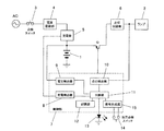
本発明にあっては、上記の課題を解決するために、図1に示すように、光源となるランプ2と、ランプ2に電力供給する2次電池1と、外部の常用電源ACから電力供給を受けて2次電池1を充電する充電手段(電源回路部4及び充電部5)と、常用電源ACの停電状態を擬似的に作り出す第1のスイッチ3と、少なくとも常用電源ACが停電したときに2次電池1からの電力供給でランプ2を点灯させる点灯手段(スイッチ素子Q及び点灯回路部6)と、2次電池1の電圧を検出する電圧検出部9と、点灯手段により所定の点検時間以上強制的にランプ2を点灯させて電圧検出部9の検出出力から2次電池1の点検を行う点検手段と、2次電池1の点検開始信号を出力する信号生成部15とを有する照明装置において、信号生成部15は、点検者が操作可能な第2のスイッチ14を操作することによって点検開始信号を出力し、点検手段による点検動作中に第1のスイッチ3または第2のスイッチ14が操作されたときに、点検動作を中断することを特徴とするものである。
In the present invention, in order to solve the above-described problem, as shown in FIG. 1, a
本発明によれば、2次電池の点検を行うために強制的にランプを点灯させる手段を備えた照明装置において、2次電池の点検動作を点検者が中断させることができる機能を付加したことにより、2次電池の不必要な放電を防ぎ、点検動作完了から2次電池が満充電されるまでの時間を短縮して、予期せぬ停電発生に対して2次電池が充電された状態を極力維持することで、より安全な照明装置を提供することができる。 According to the present invention, in the illuminating device provided with means for forcibly turning on the lamp in order to check the secondary battery, a function that allows the inspector to interrupt the check operation of the secondary battery is added. Prevents unnecessary discharge of the secondary battery, shortens the time from the completion of the inspection operation until the secondary battery is fully charged, and ensures that the secondary battery is charged when an unexpected power failure occurs. By maintaining as much as possible, a safer lighting device can be provided.
(実施形態1)
図1に本発明の実施形態1の構成を示す。本実施形態の照明装置は、非常用電源となる2次電池1と、白熱ランプや放電ランプなどからなるランプ2と、常用電源(商用電源AC)に接続された給電経路を開閉する点検スイッチ3と、点検スイッチ3を介して給電経路に接続され、商用電源ACから供給される交流を降圧し安定化して所望の直流を得る電源回路部4と、電源回路部4から出力される直流電力で2次電池1を充電する充電部5と、2次電池1からの電力供給でランプ2を点灯させる点灯回路部6と、2次電池1から点灯回路部6への給電路を開閉するスイッチ素子Qと、商用電源ACの停電、復電を検出してスイッチ素子Qをオン、オフするとともに2次電池1やランプ2などの異常を検出する制御部7と、異常検出を報知するための表示灯13とを備え、常時は商用電源ACから電力供給を受けて2次電池1を充電し、商用電源ACの停電時に2次電池1からの電力供給で非常灯であるランプ2を点灯するものである。
(Embodiment 1)
FIG. 1 shows the configuration of Embodiment 1 of the present invention. The lighting device of the present embodiment includes a secondary battery 1 serving as an emergency power source, a
また、点検作業を行うための自己点検スイッチ14と、自己点検スイッチ14が操作されることによって点検信号を発生する信号生成部15とが設けられている。これにより、点検動作を行うための操作スイッチは、本実施形態では、自己点検スイッチ14となっており、点検スイッチ3は停電状態を擬似的に作り出す手段となっている。
Further, a self-
制御部7はタイマ機能を内蔵したマイクロコンピュータを主構成要素とし、充電部5から2次電池1へ流れる充電電流の有無を検出する充電検出部8と、2次電池1の電圧(以下、「電池電圧」という)を検出する電圧検出部9と、点灯回路部6からランプ2に流れる電流(ランプ電流)を計測してランプ2の点灯、不点灯を検出する点灯検出部10と、各検出部8,9,10の検出結果から2次電池1やランプ2の異常を総合的に判断する判断部11と、EEPROM等の不揮発性メモリからなる記憶部12とを具備している。また、制御部7は点灯回路部6により所定の点検時間以上強制的にランプ2を点灯させて2次電池1の点検を行う点検機能と、2次電池1の充電状態を常時監視する監視機能とを有している。なお、表示灯13は発光ダイオードからなり、判断部11により駆動されて発光する。
The
商用電源ACから電力供給を受けているとき(常時)には、充電部5により2次電池1が充電されるとともに、制御部7によりスイッチ素子Qがオフされてランプ2を消灯させているが、停電により商用電源ACからの電力供給が停止したとき(非常時)には、充電検出部8にて充電電流が検出されなくなることで停電が検知され、制御部7によりスイッチ素子Qがオンされて2次電池1から点灯回路部6への電力供給が可能となってランプ2を点灯させるものである。そして、復電により商用電源ACからの電力供給が再開されれば、充電検出部8にて充電電流が検出されることで復電が検知され、制御部7によりスイッチ素子Qがオフされて2次電池1から点灯回路部6への電力供給が停止してランプ2を消灯させる。
When power is supplied from the commercial power supply AC (always), the secondary battery 1 is charged by the
本実施形態の照明装置においても、従来技術で説明したように消防庁告示及び建築基準法等で義務づけられている点検(2次電池1による非常点灯が正常に行われるか否かの点検)を定期的(例えば、3箇月に1回)に行う必要がある。この定期的な点検(以下、「定期点検」と呼ぶ)における制御部7の動作について図2のフローチャートを参照して説明する。
Also in the lighting device of the present embodiment, the inspection (inspection of whether or not the emergency lighting by the secondary battery 1 is normally performed) required by the Fire and Disaster Management Agency notification and the Building Standard Law, etc. as described in the prior art. It needs to be done regularly (for example, once every three months). The operation of the
まず、点検手段である自己点検スイッチ14が操作されると、制御部7の信号生成部15が点検要求信号を生成し、判断部11が図2のフローチャートの処理を開始し、記憶部12に記憶されている常用時での2次電池1の監視結果が正常か否かを判断する(ステップ1)。ここで常用時の2次電池1の監視結果(電池外れ、電池電圧低下など)が正常でなければ、判断部11は2次電池1の異常と判断し(ステップ2)、表示灯13を点灯あるいは点滅させて異常発生を報知するとともに、その点検結果(2次電池1に異常発生)を記憶部12に記憶した後(ステップ3)、2次電池1の放電を終了して点検を中止する(ステップ4)。
First, when the self-
一方、常用時の2次電池1の監視結果が正常であれば、制御部7はスイッチ素子Qをオンして2次電池1の放電を開始し(ステップ5)、点灯検出部10の検出結果からランプ2の点灯、不点灯を判別し(ステップ6)、不点灯であればランプ2の異常と判断する(ステップ7)。そして、表示灯13を点灯あるいは点滅させて異常発生を報知するとともに、その点検結果(ランプ2に異常発生)を記憶部12に記憶した後(ステップ3)、2次電池1の放電を終了して点検を中止する(ステップ4)。
On the other hand, if the monitoring result of the secondary battery 1 during normal use is normal, the
また、点灯検出部10でランプ2の点灯が検出されれば、判断部11は電圧検出部9で検出される電池電圧を所定の基準値(以下、「放電基準電圧」と呼ぶ)と比較し(ステップ8)、電池電圧が放電基準電圧以上であればステップ6に戻ってランプ2の点灯、不点灯を判別する。そして、2次電池1が放電して電池電圧が放電基準電圧を下回ったとき、判断部11はステップ5の放電開始時点からタイマによりカウントし始めた経過時間が所定の点検時間T1(例えば、一般の非常灯では30分、長時間型であれば60分)以上であるか否かを判断し(ステップ9)、経過時間が点検時間T1未満であれば2次電池1に異常が発生していると判断する(ステップ10)。そして、表示灯13を点灯あるいは点滅させて異常発生を報知するとともに、その点検結果(2次電池1に異常発生)を記憶部12に記憶した後(ステップ3)、2次電池1の放電を終了して点検を中止する(ステップ4)。
If the
一方、経過時間が点検時間T1以上であれば、判断部11は2次電池1が正常であると判断し(ステップ11)、その点検結果(2次電池1及びランプ2は正常)を記憶部12に記憶した後(ステップ3)、2次電池1の放電を終了して点検を終了する(ステップ4)。
On the other hand, if the elapsed time is equal to or longer than the inspection time T1, the
2次電池1の点検時にランプ2が正常に点灯していれば、2次電池1の電池電圧が低下するが、2次電池1の放電開始時刻からの経過時間が点検時間T1を過ぎる前に放電基準電圧を下回ることはなく、点検時間T1を過ぎた時点の電池電圧が放電基準電圧以上か否かで2次電池1が正常であるか、あるいは異常が発生しているかを判断することができる。また、ランプ2に異常があって不点灯となったときには、2次電池1の電池電圧が殆ど低下しないから、点検時間T1を過ぎた時点の電池電圧が放電基準電圧以上となって2次電池1が正常と判断される恐れがあったが、本実施形態では点検中におけるランプ2の点灯、不点灯を点灯検出部10で検出し、ランプ2が不点灯の場合には点検を中止するようにしているから、ランプ2の不点灯により2次電池1の点検が不正確になるのを防ぐことができる。
If the
本実施形態では、停電状態を擬似的に作り出す点検スイッチ3と、点検動作を行うための自己点検スイッチ14とを個別に設けることで、2次電池1によってランプ2が点灯するか否かのみを確認する作業と、上述の定期点検とを区別することが可能となる。しかし、一旦点検動作が開始されると、規定時間の点検動作が自動的に完了するのを待つことになり、点検完了後に2次電池の充電が再開しても、再び満充電状態になるまで時間を要するため、この状態において仮に商用電源が停電すると、2次電池の充電不足により規定時間のランプ点灯ができない。
In the present embodiment, only whether or not the
そこで、図2に示すフローチャートのような処理によって、定期点検動作状態を解除する手段を設ける。具体的には、定期点検動作中に自己点検スイッチ14が操作されたか否かを判断する処理(ステップ12および13)が追加されている。定期点検動作中に自己点検スイッチ14が操作されたならば、定期点検動作を中断して2次電池1の放電を終了させ、点検結果を記憶部12へ記憶することなく常用動作へ復帰する。自己点検スイッチ14が操作されていないならば、定期点検動作を継続させる。
Therefore, means for canceling the periodic inspection operation state is provided by processing as shown in the flowchart of FIG. Specifically, a process (steps 12 and 13) for determining whether or not the self-
なお、点検状態を解除するか否かの判断は、図3に示すように、自己点検スイッチ14が連続して所定時間操作されたか、または図4に示すように、操作時間の累積が所定時間以上に達したか等の判定方法によって、信号生成部15が点検信号を出力するようにすると良い。所定時間は、作業者が意図的に点検作業を解除しようとするので、例えば3秒程度に設定するのが望ましい。
Whether or not the inspection state is to be released is determined based on whether the self-
このように、実施形態1では、停電状態を擬似的に作り出す点検スイッチ3と、点検動作を行うための自己点検スイッチ14とを個別に設け、点検動作中に自己点検スイッチ14を再操作することによって点検動作を任意に中断させることができるので、点検動作の開始および解除を確実に行うことが可能となる。なお、自己点検スイッチ14の操作による点検動作中は2次電池1の充電は中止し、自己点検スイッチ14の再操作による点検中断後は2次電池1の充電を再開するように、充電部5を制御する機能を制御部7に設けておくことは言うまでも無い。
As described above, in the first embodiment, the
図5は本実施形態の一変形例の構成を示す。この構成例は、特願2002−279760の実施形態7に記載されているように、複数の照明装置と、各照明装置との間で通信線Lを介してデータの授受を行う制御装置16とで構成される非常灯あるいは誘導灯の照明システムである。この照明システムにおいても、点検要求のトリガーが自己点検スイッチ14と信号生成部15からの信号に代えて、制御装置16から通信線Lを介して通信部17が受信した点検要求信号に変わるだけなので、同様の効果がある。
FIG. 5 shows a configuration of a modification of the present embodiment. As described in the seventh embodiment of Japanese Patent Application No. 2002-279760, this configuration example includes a plurality of lighting devices and a
図5の照明装置は、自己点検スイッチ14と信号生成部15を具備しない点と、通信線Lを介してデータの授受を行うための通信部17を具備する点とを除けば、図1の照明装置と共通の構成を備えている。制御装置16は、通信線Lを介して照明装置との間でデータを授受する通信手段やマイクロコンピュータからなる制御手段、その他にEEPROMなどからなる不揮発性のメモリ等を備えている。但し、このような制御装置16は従来周知の技術で実現可能であるから詳細な構成については図示並びに説明を省略する。
The lighting device of FIG. 5 is different from that of FIG. 1 except that the self-
本実施形態においては、制御装置16が各照明装置の固有アドレスを指定して定期的(例えば、3箇月に1回)に点検開始のコマンドデータを順次送信し、このコマンドデータを受信した照明装置では、制御部7が通信部17で受信したコマンドデータを解釈して点検処理を開始し、スイッチ素子Qをオンして2次電池1からの電力供給でランプ2を点灯させ、個々の照明装置毎に制御装置16からの指令で定期点検を行う。また、各照明装置では、3箇月に1回行われる定期点検とは別に2次電池1の状態を常時監視しており、判断部11では定期点検の点検結果と監視結果を総合的に判断して2次電池1並びにランプ2の異常の有無を判断し、優先順位の高い結果を選択して制御装置16に送信している。したがって、点検作業を行う者は各照明装置の設置場所まで赴いて点検を行わなくても制御装置16によってそれぞれの照明装置の点検結果を把握することができて点検作業の省力化が図れるものである。この場合、定期点検動作の中断は、制御装置16を操作することによって実現する。
In the present embodiment, the
(実施形態2)
図6に本発明の実施形態2のフローチャートを示す。本実施形態の構成は実施形態1の図1と共通であるから、図示並びに説明は省略する。本実施形態の特徴は、定期点検動作状態を解除する手段として、商用電源の通電状態を検出することにある。
(Embodiment 2)
FIG. 6 shows a flowchart of the second embodiment of the present invention. Since the configuration of this embodiment is the same as that of FIG. 1 of the first embodiment, illustration and description thereof are omitted. The feature of this embodiment is to detect the energized state of the commercial power supply as means for canceling the periodic inspection operation state.
図6に示すフローチャートは、ステップ1〜ステップ11は実施形態1と共通であるが、本実施形態ではステップ12として、定期点検動作中に商用電源が停電したのちに復電したか否かを判断する処理を追加している。
In the flowchart shown in FIG. 6, Step 1 to Step 11 are the same as those in the first embodiment, but in this embodiment, as
実施形態1の図1の構成であれば、定期点検は商用電源が通電された状態でスイッチ素子Qをオンして強制的に2次電池1を放電させているので、商用電源は通電された状態である。従って、定期点検動作中に点検スイッチ3を操作したり、ブレーカーを開閉するなどして、停電を検出したのちに復電を検出したならば、定期点検動作を中断して2次電池1の放電を終了させ、点検結果を記憶部12へ記憶することなく常用動作へ復帰する。停電を検出しなかった場合は、定期点検動作を継続する。また、停電を検出しても復電を検出しなかった場合は、停電状態であるのでそのまま2次電池1の放電を継続する。
In the configuration of FIG. 1 according to the first embodiment, the periodic inspection is performed by turning on the switch element Q while the commercial power source is energized to forcibly discharge the secondary battery 1. State. Therefore, if a power failure is detected after a power failure is detected by operating the
点検状態を解除するか否かの判断は、実施形態1同様に、図3や図4に示すような判定方法によって行うと良く、所定時間も同様に例えば3秒程度に設定するのが望ましい。 Whether or not the inspection state is to be released may be determined by a determination method as shown in FIGS. 3 and 4 as in the first embodiment, and the predetermined time is preferably set to about 3 seconds, for example.
このように、実施形態2では、点検手段とは異なる手段を用いることによって点検動作を中断させるため、例えば複数の照明器具が接続されている場合などは、ブレーカーを開閉することで実施形態1よりも容易に点検動作を中断させることが可能となる。 As described above, in the second embodiment, the inspection operation is interrupted by using a means different from the inspection means. For example, when a plurality of lighting fixtures are connected, the breaker is opened and closed to In addition, the inspection operation can be easily interrupted.
(関連する構成1)
なお、実施形態1および実施形態2で説明した図1の点灯回路は、2次電池1のみを電源としてランプ2を点灯させても、または2次電池1と商用電源ACの双方を電源としてランプ2を点灯させても、いずれでも構わない。2次電池1と商用電源ACの双方を電源とする場合は、図7のような構成となる。図7の構成例は、特願2002−279760の実施形態8に記載されているように、常時及び非常時ともにランプ2を点灯させるタイプの非常灯あるいは誘導灯として構成されている。すなわち、図7の破線に示すように、電源回路部4の出力を充電部5だけでなく点灯回路部6にも入力し、常時においても商用電源ACからの電力供給でランプ2を点灯させ、非常時には制御部7によりスイッチ素子Q1をオンして2次電池1からの電力供給でランプ2を点灯させるものである。なお、本実施形態では常時においてもランプ2を点灯させるから、常用時の監視項目(図2または図6のステップ1の判定対象)にランプ2の点灯、不点灯の検出も追加する必要がある。
(Related configuration 1)
Note that the lighting circuit of FIG. 1 described in the first and second embodiments may be operated by using only the secondary battery 1 as a power source and lighting the
(関連する構成2)
また、図5の構成例と同様に、図7における自己点検スイッチ14と信号生成部15の代わりに制御装置16と通信部17を具備した、図8のような照明システムの構成であっても、同様の効果を得られる。この場合、定期点検動作の中断は、制御装置16を操作することによって実現する。
(Related configuration 2)
Similarly to the configuration example of FIG. 5, the configuration of the illumination system as shown in FIG. 8, which includes the
1 2次電池
2 ランプ
3 点検スイッチ
4 電源回路部
5 充電部
6 点灯回路部
7 制御部
9 電圧検出部
11 判断部
14 自己点検スイッチ
15 信号生成部
DESCRIPTION OF SYMBOLS 1
Claims (3)
Priority Applications (1)
| Application Number | Priority Date | Filing Date | Title |
|---|---|---|---|
| JP2003409471A JP4627980B2 (en) | 2003-12-08 | 2003-12-08 | Lighting device and lighting system |
Applications Claiming Priority (1)
| Application Number | Priority Date | Filing Date | Title |
|---|---|---|---|
| JP2003409471A JP4627980B2 (en) | 2003-12-08 | 2003-12-08 | Lighting device and lighting system |
Related Child Applications (1)
| Application Number | Title | Priority Date | Filing Date |
|---|---|---|---|
| JP2007124538A Division JP4208021B2 (en) | 2007-05-09 | 2007-05-09 | Lighting device and lighting system |
Publications (3)
| Publication Number | Publication Date |
|---|---|
| JP2005174611A JP2005174611A (en) | 2005-06-30 |
| JP2005174611A5 JP2005174611A5 (en) | 2007-06-28 |
| JP4627980B2 true JP4627980B2 (en) | 2011-02-09 |
Family
ID=34730847
Family Applications (1)
| Application Number | Title | Priority Date | Filing Date |
|---|---|---|---|
| JP2003409471A Expired - Lifetime JP4627980B2 (en) | 2003-12-08 | 2003-12-08 | Lighting device and lighting system |
Country Status (1)
| Country | Link |
|---|---|
| JP (1) | JP4627980B2 (en) |
Families Citing this family (5)
| Publication number | Priority date | Publication date | Assignee | Title |
|---|---|---|---|---|
| JP4506643B2 (en) * | 2005-10-31 | 2010-07-21 | パナソニック電工株式会社 | Display lighting fixture |
| JP4798352B2 (en) * | 2005-12-01 | 2011-10-19 | 東芝ライテック株式会社 | Lighting fixture and lighting system |
| JP4771141B2 (en) * | 2006-03-01 | 2011-09-14 | 東芝ライテック株式会社 | Emergency lighting system |
| JP5062470B2 (en) * | 2006-11-16 | 2012-10-31 | 東芝ライテック株式会社 | Emergency lighting equipment inspection system |
| JP2011171314A (en) * | 2011-06-07 | 2011-09-01 | Toshiba Lighting & Technology Corp | Luminaire and lighting system |
-
2003
- 2003-12-08 JP JP2003409471A patent/JP4627980B2/en not_active Expired - Lifetime
Also Published As
| Publication number | Publication date |
|---|---|
| JP2005174611A (en) | 2005-06-30 |
Similar Documents
| Publication | Publication Date | Title |
|---|---|---|
| JP4609327B2 (en) | Emergency lighting system | |
| JP4556756B2 (en) | Lighting device, lighting fixture, lighting system | |
| JP4208021B2 (en) | Lighting device and lighting system | |
| JP4627980B2 (en) | Lighting device and lighting system | |
| JP4720513B2 (en) | Emergency lighting system | |
| JP4487548B2 (en) | Lighting device and lighting system | |
| JP4329633B2 (en) | Emergency light inspection system | |
| JP4428397B2 (en) | Lighting device and lighting system | |
| JPH08185987A (en) | Emergency lighting system | |
| JP4228802B2 (en) | Lighting device and lighting system | |
| JP4720273B2 (en) | Lighting equipment | |
| JP4229197B2 (en) | Lighting device and lighting system | |
| JP2005174612A5 (en) | ||
| JP4284456B2 (en) | Disaster prevention lighting and disaster prevention lighting system | |
| JP4428398B2 (en) | Lighting device and lighting system | |
| JP5582900B2 (en) | Guide light and guide light control system | |
| JP4013167B2 (en) | Emergency lighting system | |
| JP4957973B2 (en) | Disaster prevention lighting | |
| JP4479605B2 (en) | Emergency lighting automatic inspection system | |
| JP2007035652A (en) | Emergency lighting device | |
| JP4661105B2 (en) | Lighting device and lighting system | |
| JP2007059115A (en) | Emergency lighting automatic inspection system | |
| JP2007087840A (en) | Emergency lighting fitting | |
| JP4661117B2 (en) | Lighting system | |
| JP4363258B2 (en) | Lighting device and lighting system |
Legal Events
| Date | Code | Title | Description |
|---|---|---|---|
| A621 | Written request for application examination |
Free format text: JAPANESE INTERMEDIATE CODE: A621 Effective date: 20061113 |
|
| A521 | Request for written amendment filed |
Free format text: JAPANESE INTERMEDIATE CODE: A523 Effective date: 20070509 |
|
| A977 | Report on retrieval |
Free format text: JAPANESE INTERMEDIATE CODE: A971007 Effective date: 20090724 |
|
| A131 | Notification of reasons for refusal |
Free format text: JAPANESE INTERMEDIATE CODE: A131 Effective date: 20090728 |
|
| A521 | Request for written amendment filed |
Free format text: JAPANESE INTERMEDIATE CODE: A523 Effective date: 20090925 |
|
| A02 | Decision of refusal |
Free format text: JAPANESE INTERMEDIATE CODE: A02 Effective date: 20100126 |
|
| A01 | Written decision to grant a patent or to grant a registration (utility model) |
Free format text: JAPANESE INTERMEDIATE CODE: A01 |
|
| A61 | First payment of annual fees (during grant procedure) |
Free format text: JAPANESE INTERMEDIATE CODE: A61 Effective date: 20101109 |
|
| FPAY | Renewal fee payment (event date is renewal date of database) |
Free format text: PAYMENT UNTIL: 20131119 Year of fee payment: 3 |
|
| R150 | Certificate of patent or registration of utility model |
Free format text: JAPANESE INTERMEDIATE CODE: R150 Ref document number: 4627980 Country of ref document: JP Free format text: JAPANESE INTERMEDIATE CODE: R150 |
|
| EXPY | Cancellation because of completion of term |