JP4487548B2 - Lighting device and lighting system - Google Patents
Lighting device and lighting system Download PDFInfo
- Publication number
- JP4487548B2 JP4487548B2 JP2003409472A JP2003409472A JP4487548B2 JP 4487548 B2 JP4487548 B2 JP 4487548B2 JP 2003409472 A JP2003409472 A JP 2003409472A JP 2003409472 A JP2003409472 A JP 2003409472A JP 4487548 B2 JP4487548 B2 JP 4487548B2
- Authority
- JP
- Japan
- Prior art keywords
- secondary battery
- time
- charging
- power
- lighting
- Prior art date
- Legal status (The legal status is an assumption and is not a legal conclusion. Google has not performed a legal analysis and makes no representation as to the accuracy of the status listed.)
- Expired - Lifetime
Links
- 238000011084 recovery Methods 0.000 claims abstract description 21
- 238000012544 monitoring process Methods 0.000 claims abstract description 17
- 238000007689 inspection Methods 0.000 claims description 88
- 238000001514 detection method Methods 0.000 claims description 30
- 238000007599 discharging Methods 0.000 claims description 27
- 230000005611 electricity Effects 0.000 claims description 10
- 230000005856 abnormality Effects 0.000 claims description 6
- 238000005286 illumination Methods 0.000 claims description 6
- 238000000034 method Methods 0.000 description 22
- 230000008569 process Effects 0.000 description 16
- 230000008859 change Effects 0.000 description 7
- 238000004891 communication Methods 0.000 description 7
- 230000006870 function Effects 0.000 description 6
- 238000012986 modification Methods 0.000 description 4
- 230000004048 modification Effects 0.000 description 4
- 238000004364 calculation method Methods 0.000 description 3
- 238000010586 diagram Methods 0.000 description 3
- 230000000737 periodic effect Effects 0.000 description 3
- 230000006866 deterioration Effects 0.000 description 2
- 238000012545 processing Methods 0.000 description 2
- 230000001186 cumulative effect Effects 0.000 description 1
- 230000000694 effects Effects 0.000 description 1
- 238000009434 installation Methods 0.000 description 1
- 238000012886 linear function Methods 0.000 description 1
- 230000009467 reduction Effects 0.000 description 1
- 238000004904 shortening Methods 0.000 description 1
- 238000012360 testing method Methods 0.000 description 1
Images


Classifications
-
- Y—GENERAL TAGGING OF NEW TECHNOLOGICAL DEVELOPMENTS; GENERAL TAGGING OF CROSS-SECTIONAL TECHNOLOGIES SPANNING OVER SEVERAL SECTIONS OF THE IPC; TECHNICAL SUBJECTS COVERED BY FORMER USPC CROSS-REFERENCE ART COLLECTIONS [XRACs] AND DIGESTS
- Y02—TECHNOLOGIES OR APPLICATIONS FOR MITIGATION OR ADAPTATION AGAINST CLIMATE CHANGE
- Y02B—CLIMATE CHANGE MITIGATION TECHNOLOGIES RELATED TO BUILDINGS, e.g. HOUSING, HOUSE APPLIANCES OR RELATED END-USER APPLICATIONS
- Y02B20/00—Energy efficient lighting technologies, e.g. halogen lamps or gas discharge lamps
- Y02B20/40—Control techniques providing energy savings, e.g. smart controller or presence detection
Abstract
Description
本発明は、誘導灯や非常灯のように、常用の電源が停電したときに2次電池などの非常用の電源でランプを点灯させ、特に点検機能を持つ照明装置に関するものである。 The present invention relates to an illuminating device having an inspection function, such as a guide light or an emergency light, which turns on a lamp with an emergency power source such as a secondary battery when a normal power source fails.
誘導灯や非常灯の点検は、消防庁告示、建築基準法等で義務付けされているが、規定では誘導灯が20分間又は60分間、非常灯の場合は30分間、ランプを有効に2次電池で非常点灯させなければいけない。従って、通常点検者は、このように長時間点灯させ続けるために、点検スイッチの引き輪に重りをぶら下げるなどして、上記規定時間内にランプが有効に非常点灯可能か否かを見て廻る必要があり、非常に手間のかかる作業であった。 The inspection of guide lights and emergency lights is obligated by the Fire and Disaster Management Agency Notification, Building Standards Law, etc., but by regulation, the guide lights are used for 20 minutes or 60 minutes, and in the case of emergency lights, the lamps are used effectively for 30 minutes. It must be lit at the emergency. Therefore, in order to keep the light on for a long time in this way, the normal checker hangs a weight on the pulling wheel of the check switch to see whether the lamp can be effectively lit within the specified time. It was necessary and very laborious.
そこで、点検作業の省力化を図るために点検作業を自動化する方法が、特願2002−279760に開示されている。上述される開示例における照明装置では、正確な点検を行うために、満充電されていない状態で2次電池の点検が行われないよう、常用電源の通電時間が所定充電時間(誘導灯では24時間、非常灯では48時間)に達するまでは点検を開始しないことを特徴としている。 Therefore, Japanese Patent Application No. 2002-279760 discloses a method of automating the inspection work in order to save labor of the inspection work. In the lighting device in the above-described disclosure, in order to perform an accurate inspection, the energization time of the normal power supply is set to a predetermined charging time (24 for the guide light) so that the secondary battery is not inspected in a state where it is not fully charged. The inspection is not started until the time reaches 48 hours for emergency lights.
なお、特許文献1には、点検者が短時間だけ点検スイッチをオンすれば、点検シーケンス手段によって所定の点検作業が実行され、2次電池に異常があれば表示手段で表示することで2次電池の点検作業の自動化、省力化を図った照明装置が提案されている。
特願2002−279760では、満充電されていない状態で2次電池の点検が行われるのを防ぐことが出来るが、所定充電時間(2次電池が規定時間放電による点検を行うのに必要な電気量を充電する時間)に到達する前に短時間の停電(例えば瞬時停電や、点検スイッチやブレーカー等の誤操作)が発生すると、復電してから再び所定充電時間経過しなければ、点検可能な状態にならない。また、所定充電時間に到達して点検可能な状態で短時間の停電が発生しても、復電してから所定時間充電しないと点検可能な状態にならないという課題がある。 In Japanese Patent Application No. 2002-279760, it is possible to prevent the secondary battery from being inspected in a state where it is not fully charged, but a predetermined charging time (electricity necessary for the secondary battery to perform inspection by discharging for a specified time) If a short-time power outage (for example, an instantaneous power outage or an erroneous operation of the inspection switch or breaker) occurs before reaching the amount of time), inspection can be performed if the specified charging time does not elapse after the power is restored. It will not be in a state. In addition, even if a short-time power failure occurs in a state where the predetermined charging time has been reached and can be inspected, there is a problem that the inspection cannot be performed unless charging is performed for a predetermined time after power recovery.
本発明は、このような点に鑑みてなされたものであり、その目的とするところは、瞬時停電が起こりやすい場所や、容易に点検スイッチを押せる場所においても、確実に点検を行えるようにすることにある。 The present invention has been made in view of the above points, and the object of the present invention is to make sure that inspection can be performed even in a place where an instantaneous power failure is likely to occur or a place where an inspection switch can be easily pressed. There is.
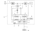
本発明にあっては、上記の課題を解決するために、図1に示すように、光源となるランプ2と、ランプ2に電力供給する2次電池1と、外部の常用電源ACから電力供給を受けて2次電池1を充電し所定の時間充電された時に点検可能となるような充電手段(電源回路部4及び充電部5)と、少なくとも常用電源ACが停電したときに2次電池1からの電力供給でランプ2を点灯させる点灯手段(スイッチ素子Q及び点灯回路部6)と、充電手段による2次電池1の充電の有無を検出する充電検出部8と、2次電池1の電圧を検出する電圧検出部9と、点灯手段により所定の点検時間以上強制的にランプ2を点灯させて2次電池1の点検を行う点検手段(制御部7の点検機能)と、少なくとも2次電池1の充電状態を含む1乃至複数の動作状態を常時監視する監視手段(制御部7の監視機能)と、常用電源ACが停電後に復電してからの充電時間と常用電源ACが通電後に停電してからの放電時間との少なくとも一方の時間をカウントするカウント手段(制御部7のタイマー機能)を有する照明装置において、図2に示すように、前記カウント手段が充電時間カウント中に常用電源ACの停電が発生した時、停電が短時間であればカウント値を初期化せず、復電後の充電時間カウントを停電発生直前の状態から継続することを特徴とするものである。
In the present invention, in order to solve the above-described problem, as shown in FIG. 1, a
請求項1の発明によれば、所定充電時間到達前に短時間の停電が起こっても、充電時間を継続してカウントするので、再び初期値から所定充電時間経過するのを待たなくても点検が出来るようになる。また、所定充電時間到達後に短時間の停電が起こった場合は、点検可能な状態を継続出来る。
請求項2の発明によれば、所定充電時間経過していない状態でも、その時点での充電時間に応じて判定時間を変えることによって、充電状態であれば常に点検可能な状態となり、2次電池の充放電効率の劣化などを早期に検出することができる。
According to the first aspect of the present invention, even if a short interruption occurs before the predetermined charging time is reached, the charging time is continuously counted. Therefore, the inspection can be performed without waiting for the predetermined charging time to elapse from the initial value again. Will be able to. Moreover, when a short-time power failure occurs after the predetermined charging time has been reached, it is possible to continue the inspectable state.
According to the second aspect of the present invention, even when the predetermined charging time has not elapsed, the determination time is changed according to the charging time at that time, so that the battery can be inspected at all times in the charged state. It is possible to detect the deterioration of the charging / discharging efficiency at an early stage .
請求項3の発明によれば、所定充電時間経過した状態から停電によって放電した時間と、復電してからの充電時間によって判定時間を変化させることで、所定充電時間経過した状態を基準としているので、請求項2よりも判定精度を向上させることができ、容量低下を早期に検出することができる。
請求項4の発明によれば、充電時間と放電時間から充電電気量と放電電気量を求め、補充電時間と判定時間を常に算出することで、常に点検可能な状態とすることができ、かつ2次電池の判定精度を向上させることができる。
According to the third aspect of the present invention, the determination time is changed according to the time when the predetermined charging time has elapsed and the discharge time due to the power failure and the charging time after the power recovery, so that the state where the predetermined charging time has elapsed is used as a reference. Therefore, the determination accuracy can be improved as compared with the second aspect, and the capacity drop can be detected at an early stage.
According to the invention of
(実施形態1)
本実施形態の照明装置は、図1に示すように、非常用電源となる2次電池1と、白熱ランプや放電ランプなどからなるランプ2と、常用電源(商用電源AC)に接続された給電経路を開閉する点検スイッチ3と、点検スイッチ3を介して給電経路に接続され、商用電源ACから供給される交流を降圧し安定化して所望の直流を得る電源回路部4と、電源回路部4から出力される直流電力で2次電池1を充電する充電部5と、2次電池1からの電力供給でランプ2を点灯させる点灯回路部6と、2次電池1から点灯回路部6への給電路を開閉するスイッチ素子Qと、商用電源ACの停電、復電を検出してスイッチ素子Qをオン、オフするとともに2次電池1やランプ2などの異常を検出する制御部7と、異常検出を報知するための表示灯13とを備え、常時は商用電源ACから電力供給を受けて2次電池1を充電し、商用電源ACの停電時に2次電池1からの電力供給で非常灯であるランプ2を点灯するものである。
(Embodiment 1)
As shown in FIG. 1, the lighting device of this embodiment includes a secondary battery 1 serving as an emergency power source, a
制御部7はタイマ機能を内蔵したマイクロコンピュータを主構成要素とし、充電部5から2次電池1へ流れる充電電流の有無を検出する充電検出部8と、2次電池1の電圧(以下、「電池電圧」という)を検出する電圧検出部9と、点灯回路部6からランプ2に流れる電流(ランプ電流)を計測してランプ2の点灯、不点灯を検出する点灯検出部10と、各検出部8,9,10の検出結果から2次電池1やランプ2の異常を総合的に判断する判断部11と、EEPROM等の不揮発性メモリからなる記憶部12とを具備している。また、制御部7は点灯回路部6により所定の点検時間以上強制的にランプ2を点灯させて2次電池1の点検を行う点検機能と、2次電池1の充電状態を常時監視する監視機能とを有している。すなわち、本実施形態では制御部7で点検手段並びに監視手段を構成し、判断部11で異常検出手段を構成している。なお、表示灯13は発光ダイオードからなり、判断部11により駆動されて発光する。
The
商用電源ACから電力供給を受けているとき(常時)には、充電部5により2次電池1が充電されるとともに、制御部7によりスイッチ素子Qがオフされてランプ2を消灯させているが、停電により商用電源ACからの電力供給が停止したとき(非常時)には、充電検出部8にて充電電流が検出されなくなることで停電が検知され、制御部7によりスイッチ素子Qがオンされて2次電池1から点灯回路部6への電力供給が可能となってランプ2を点灯させるものである。そして、復電により商用電源ACからの電力供給が再開されれば、充電検出部8にて充電電流が検出されることで復電が検知され、制御部7によりスイッチ素子Qがオフされて2次電池1から点灯回路部6への電力供給が停止してランプ2を消灯させる。
When power is supplied from the commercial power supply AC (always), the secondary battery 1 is charged by the
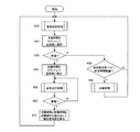
本実施形態における制御部の動作を図2のフローチャートを参照して説明する。本実施形態の特徴は、短時間(例えば3秒)の停電が発生した時には充電時間カウントを継続もしくは点検可能状態を維持することである。フローチャートの#は処理ステップの番号を意味する。 The operation of the control unit in this embodiment will be described with reference to the flowchart of FIG. A feature of the present embodiment is that the charging time count is continued or can be checked when a power failure occurs for a short time (for example, 3 seconds). # In the flowchart means a process step number.
制御部7は、充電検出部8によって充電電流の有無を検出し、2次電池1の充電時間をカウントしている(#10,#20)。商用電源ACの停電を検出すると(#30)、復電してからの充電時間カウント値をEEPROM等の不揮発性メモリからなる記憶部12に記憶させて(#40)、充電時間カウント値をリセットして(#41)、スイッチ素子Qをオンして2次電池1からの電源供給でランプ2を非常点灯させる(#50)。なお、停電時の制御部7の動作電源は2次電池1から供給する。
The
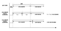
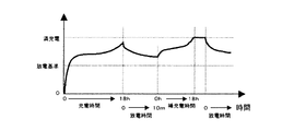
ここで、商用電源ACが復電すると(#60)、停電した時間が短時間であるかを判断し(#70)、短時間であれば記憶部12に記憶させた停電発生前の充電時間カウント値を読み出し(#71)、そこから継続して充電時間をカウントし、短時間でなければ復電した時点からの充電時間を初期値(#41でリセットした値)からカウントし直す。停電した時間が短時間であるかの判断については、図3に示すように、連続した停電時間(Ta)が所定時間以内(例えば3秒以内)であるか否か、または累積停電時間(Tb1+Tb2+Tb3)が所定時間以内であるか否か、いずれの判定方法であっても良い。
Here, when the commercial power supply AC recovers (# 60), it is determined whether the power failure time is short (# 70), and if it is short time, the charging time before the power failure stored in the
制御部7は点検スイッチ3の状態を監視しており、商用電源ACが停電していない常時において点検スイッチ3が操作されたことを検出すると、その時点までの充電時間が所定充電時間を超えているかを判断し、超えていればスイッチ素子Qをオンして点検処理を行い、超えていなければ点検処理を行わない(#80,#90)。
When the
本実施形態では、図4に示すように、所定充電時間到達前に短時間の停電が起こっても、充電時間を継続してカウントするので、例えば瞬時停電や、点検スイッチやブレーカー等の誤操作による停電状態が起こった場合は再び初期値から所定の充電時間が経過するのを待たなくても点検が出来るようになる。また、所定充電時間到達後に短時間の停電が起こった場合も、点検可能な状態を継続出来る。 In this embodiment, as shown in FIG. 4, even if a short interruption occurs before reaching the predetermined charging time, the charging time is continuously counted. For example, due to an instantaneous interruption or an erroneous operation such as an inspection switch or a breaker. When a power failure occurs, the inspection can be performed without waiting for the predetermined charging time to elapse from the initial value. Moreover, even if a short-time power failure occurs after the predetermined charging time is reached, it is possible to continue the checkable state.
図5は本実施形態の一変形例の構成を示す。この構成例は、特願2002−279760の実施形態7に記載されているように、複数の照明装置Ai(i=1,2,…,n)と、各照明装置との間で通信線Lを介してデータの授受を行う制御装置Bとで構成される非常灯あるいは誘導灯の照明システムである。この照明システムにおいても、点検要求のトリガーが点検スイッチ3からの信号に代えて、制御装置Bからの信号に変わるだけなので、同様の効果がある。
FIG. 5 shows a configuration of a modification of the present embodiment. In this configuration example, as described in
図5の照明装置は、点検スイッチ3及び表示灯13を具備しない点と、通信線Lを介してデータの授受を行うための通信部15並びに通信のためのアドレスを設定するアドレス設定部16とを具備する点とを除けば、図1の照明装置と共通の構成を備えている。
The lighting device of FIG. 5 does not include the
アドレス設定部16はディップスイッチなどで構成されており、各照明装置Ai(i=1,2,…,n)に固有のアドレスの他に複数の照明装置からなるグループを特定するためのグループ番号も設定可能であって、照明システムの施工時にアドレス設定が行われる。
The
制御装置Bは、通信線Lを介して照明装置Ai(i=1,2,…,n)との間でデータを授受する通信手段やマイクロコンピュータからなる制御手段、その他にEEPROMなどからなる不揮発性のメモリ等を備えている。但し、このような制御装置Bは従来周知の技術で実現可能であるから詳細な構成については図示並びに説明を省略する。 The control device B is a non-volatile memory composed of a communication means that exchanges data with the illumination device Ai (i = 1, 2,..., N) via the communication line L, a control means that includes a microcomputer, and an EEPROM. Memory etc. However, since such a control device B can be realized by a conventionally well-known technique, illustration and description of a detailed configuration are omitted.
本実施形態においては、制御装置Bが各照明装置Aiの固有アドレスiを指定して定期的に(例えば、3箇月に1回)点検開始のコマンドデータを順次送信し、このコマンドデータを受信した照明装置Aiでは、制御部7が通信部15で受信したコマンドデータを解釈して点検処理を開始し、スイッチ素子Qをオンして2次電池1からの電力供給でランプ2を点灯させ、個々の照明装置Ai毎に制御装置Bからの指令で定期点検を行う。また、各照明装置Aiでは、3箇月に1回行われる定期点検とは別に2次電池1の状態を常時監視しており、判断部11では定期点検の点検結果と監視結果を総合的に判断して2次電池1並びにランプ2の異常の有無を判断し、優先順位の高い結果を選択して制御装置Bに送信している。したがって、点検作業を行う者は各照明装置Aiの設置場所まで赴いて点検を行わなくても制御装置Bによってそれぞれの照明装置Aiの点検結果を把握することができて点検作業の省力化が図れるものである。
In the present embodiment, the control device B designates the unique address i of each lighting device Ai, and regularly transmits command data for starting inspection periodically (for example, once every three months), and receives this command data. In the lighting device Ai, the
図6は実施形態1の他の変形例の構成を示す。この構成例は、特願2002−279760の実施形態8に記載されているように、常時及び非常時ともにランプを点灯させるタイプの非常灯あるいは誘導灯として構成されている。すなわち、図6に示すように、電源回路部4の出力を充電部5だけでなく点灯回路部6にも入力し、常時においても商用電源ACからの電力供給でランプ2を点灯させ、非常時には制御部7によりスイッチ素子Qをオンして2次電池1からの電力供給でランプ2を点灯させるものである。なお、本実施形態では常時においてもランプ2を点灯させるから、常時の監視項目(#10の常用状態処理)にランプ2の点灯、不点灯の検出も追加する必要がある。
また、これらの図5、図6の構成は以下に説明するいずれの実施形態においても同様に実施できる。
FIG. 6 shows a configuration of another modification of the first embodiment. As described in the eighth embodiment of Japanese Patent Application No. 2002-279760, this configuration example is configured as an emergency light or a guide light of a type that lights the lamp at all times and in an emergency. That is, as shown in FIG. 6, the output of the power
5 and 6 can be similarly implemented in any of the embodiments described below.
(実施形態2)
本実施形態における制御部の動作を図7のフローに示す。本実施形態の特徴は、2次電池の所定の充電時間が経過する前に停電が発生したときに、それまでの充電時間に応じて放電時の判定時間を変化させることにある。なお、本実施形態における照明装置の構成は実施形態1と同じであるから図示並びに説明は省略する。
(Embodiment 2)
The operation of the control unit in this embodiment is shown in the flow of FIG. The feature of this embodiment is that when a power failure occurs before a predetermined charging time of the secondary battery elapses, the determination time at the time of discharging is changed according to the charging time up to that time. In addition, since the structure of the illuminating device in this embodiment is the same as Embodiment 1, illustration and description are abbreviate | omitted.
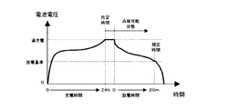
特願2002−279760では所定充電時間(例えば24時間)が経過した後で点検可能状態となり、点検可能状態において点検要求があると、規定時間(例えば20分間)放電し点検を行う(図8)。これに対して本実施形態では、所定充電時間が経過していなくても、点検要求があれば2次電池を放電させ、点検を行う。例えば、誘導灯において、充電時間が18時間で点検要求が来ると、本来必要である充電時間の75%しか経過していないので、例えば規定時間の75%に相当する15分間の放電によって判定を行う(図9)。なお、電池電圧と時間の関係を示すグラフにおいて、横軸の単位[h]は時間、単位[m]は分を意味する。以下の各実施形態においても同様である。 In Japanese Patent Application No. 2002-279760, after a predetermined charging time (for example, 24 hours) elapses, the inspection becomes possible, and when there is an inspection request in the inspectable state, discharge is performed for a specified time (for example, 20 minutes) (FIG. 8). . On the other hand, in this embodiment, even if the predetermined charging time has not elapsed, if there is an inspection request, the secondary battery is discharged and the inspection is performed. For example, when an inspection request is received with a charging time of 18 hours for a guide light, only 75% of the originally required charging time has elapsed, so for example, the determination is made by discharging for 15 minutes corresponding to 75% of the specified time. Perform (FIG. 9). In the graph showing the relationship between battery voltage and time, the unit [h] on the horizontal axis means time, and the unit [m] means minute. The same applies to the following embodiments.
判定時間の算出法は、図10に示すように、所定充電時間(満充電に要する充電時間)に対して充電時間が短くなれば、その分、判定時間を規定時間に対して短くする。図10では、充電時間に比例して判定時間を変化させる例を示しているが、変化の度合いは比例関係に限定されるものではなく、例えば2次電池の充放電効率によって傾きや切片を変更したり、1次関数以外の計算式であっても構わない。これは、以下に説明する図14、図17、図20においても同様である。 As shown in FIG. 10, the determination time is calculated by shortening the determination time relative to the specified time if the charge time is shorter than the predetermined charge time (charge time required for full charge). FIG. 10 shows an example in which the determination time is changed in proportion to the charging time, but the degree of change is not limited to the proportional relationship, and for example, the slope or intercept is changed depending on the charge / discharge efficiency of the secondary battery. Or a calculation formula other than a linear function. This 14 you discussed below, FIG. 17 is the same in FIG. 20.
本実施形態における制御部の動作を図7のフローチャートを参照して説明する。制御部は、常用状態処理において、充電検出部によって充電電流の有無を検出し、2次電池の充電時間をカウントしている(#10,#20)。ここで点検要求があれば(#80)、その時点までの充電時間をもとに制御部で判定時間を算出し(#85)、点検の判定時間を変えて、スイッチ素子Qをオンして点検処理を行う(#90)。 The operation of the control unit in this embodiment will be described with reference to the flowchart of FIG. In the normal state process, the control unit detects the presence or absence of a charging current by the charge detection unit, and counts the charging time of the secondary battery (# 10, # 20). If there is an inspection request (# 80), the control unit calculates a determination time based on the charging time up to that point (# 85), changes the inspection determination time, and turns on the switch element Q. An inspection process is performed (# 90).
このように本実施形態では、所定充電時間経過していない状態でも、その時点での充電時間に応じて判定時間を変えることによって、充電状態であれば常に点検可能な状態となり、2次電池の充放電効率の劣化などを早期に検出することができる。 As described above, in the present embodiment, even when the predetermined charging time has not elapsed, by changing the determination time according to the charging time at that time, the charging state is always inspectable, and the secondary battery It is possible to detect deterioration of charge / discharge efficiency at an early stage.
(関連する構成1)
本構成例における制御部の動作を図11のフローに示す。本構成例の特徴は、2次電池が所定充電時間経過した状態で停電が発生したとき、停電によって放電した時間に応じて、復電後の点検可能状態になるまでの充電時間を変化させることにある。なお、本構成例における照明装置の構成も実施形態1と同じであるから、図示並びに説明は省略する。
( Related configuration 1 )
The operation of the control unit in this configuration example is shown in the flow of FIG. The feature of this configuration example is that, when a power failure occurs when a predetermined charging time has elapsed for the secondary battery, the charging time until the inspection is possible after power recovery is changed according to the time discharged by the power failure. It is in. In addition, since the structure of the illuminating device in this structural example is also the same as Embodiment 1, illustration and description are abbreviate | omitted.
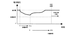
特願2002−279760では所定時間充電された状態から停電して復電すると、再び所定充電時間(例えば24時間)経過しなくては、点検可能状態にならなかった(図12)。これに対して本構成例では、所定時間充電された状態(満充電状態)から停電して復電すると、放電時間から判断して、あとどれだけ充電すれば所定充電時間経過した状態と同等の電気量になるか(以下「補充電時間」とする)を算出し、その分だけ充電すれば点検可能状態になる。例えば誘導灯において、所定時間充電された状態から15分間停電して復電すると、2次電池の放電による点検の規定時間20分に対して75%相当しか放電していないので、所定の充電時間の75%である18時間充電すれば点検可能状態となる(図13)。補充電時間の算出方法は、規定時間に対して放電した時間(停電時間)が短ければその分補充電時間を所定時間に対して短くする(図14)。 In Japanese Patent Application No. 2002-279760, when a power failure occurred after the power was charged for a predetermined time and power was restored, the test could not be performed until a predetermined charge time (for example, 24 hours) had passed again (FIG. 12). On the other hand, in this configuration example , when power is restored from a state charged for a predetermined time (full charge state) and power is restored, it is determined from the discharge time, and how much more charging is required is equivalent to the state after the predetermined charging time has elapsed. If the amount of electricity is reached (hereinafter referred to as “supplementary charging time”) and charging is performed by that amount, inspection is possible. For example, in a guide lamp, if a power failure is restored for 15 minutes after being charged for a predetermined time, only 75% of the specified time for inspection by discharging of the secondary battery is discharged, equivalent to 75%. If it is charged for 18 hours, which is 75% of the above, the inspection is possible (FIG. 13). In the calculation method of the auxiliary charging time, if the discharging time (power failure time) is shorter than the specified time, the auxiliary charging time is shortened by a corresponding amount (FIG. 14).
本構成例における制御部の動作を図11のフローチャートを参照して説明する。制御部は、常用状態処理において、充電検出部によって充電電流の有無を検出し、2次電池の充電時間をカウントしている(#10,#20)。ここで商用電源ACが停電すると(#30)、所定時間充電されていたかを判断し(#42)、充電されていれば、放電時間をカウントして記憶部に保存する処理を開始し(#43)、スイッチ素子Qをオンして2次電池からの電源供給でランプを非常点灯させる(#50)。#42で所定時間充電されていなければ、放電時間カウントをせずに非常点灯させる。商用電源ACが復電すると(#60)、放電時間カウント値を記憶部から読み出し、制御部で図14の演算を行い、必要な補充電時間を算出する。補充電時間が経過すれば、点検可能状態となる。なお、放電時間カウントをせずに非常点灯させた場合は、放電時間=規定時間(20分間)とみなして、補充電時間=所定時間(24時間)とすれば良い。 The operation of the control unit in this configuration example will be described with reference to the flowchart of FIG. In the normal state process, the control unit detects the presence or absence of a charging current by the charge detection unit, and counts the charging time of the secondary battery (# 10, # 20). Here, when the commercial power supply AC is out of power (# 30), it is determined whether it has been charged for a predetermined time (# 42), and if it is charged, a process of counting the discharge time and storing it in the storage unit is started (# 43) The switch element Q is turned on, and the lamp is turned on by power supply from the secondary battery (# 50). If the battery has not been charged for a predetermined time in # 42, the emergency lighting is performed without counting the discharge time. When the commercial power supply AC recovers (# 60), the discharge time count value is read from the storage unit, and the control unit performs the calculation of FIG. 14 to calculate the necessary supplementary charging time. When the auxiliary charging time has elapsed, the inspection is possible. When the emergency lighting is performed without counting the discharge time, it is considered that the discharge time is equal to the specified time (20 minutes), and the auxiliary charge time is equal to the predetermined time (24 hours).
このように本構成例では、所定充電時間経過した状態から停電すると、放電時間に応じて補充電時間を設定するので、復電後に点検可能状態になる迄の時間を短縮することが出来る。 As described above, in this configuration example , when a power failure occurs after a predetermined charging time has elapsed, the supplementary charging time is set according to the discharging time, so the time until the inspection can be performed after the power recovery can be shortened.
(関連する構成2)
本構成例における制御部の動作を図15のフローに示す。本構成例の特徴は、所定時間充電されてない状態で停電したとき、停電になるまでの充電時間と停電による放電時間に応じて、復電後の補充電時間を決めることにある。なお、本構成例における照明装置の構成も実施形態1と同じであるから、図示並びに説明は省略する。
( Related configuration 2 )
The operation of the control unit in this configuration example is shown in the flow of FIG. A feature of this configuration example is that, when a power failure occurs in a state where the battery is not charged for a predetermined time, a supplementary charging time after power recovery is determined according to a charging time until the power failure occurs and a discharging time due to the power failure. In addition, since the structure of the illuminating device in this structural example is also the same as Embodiment 1, illustration and description are abbreviate | omitted.
関連する構成1では、放電時間のみから補充電時間を算出するため、所定時間充電されてない状態で停電すると補充電時間を算出できなかった。これに対して本構成例では、所定時間充電されていない状態で停電しても補充電時間を算出できる。例えば誘導灯において、充電時間が18時間で5分間停電すると、充電時間が所定充電時間24時間に対して75%、放電時間が規定時間20分に対して25%相当であるので、75%−25%=50%に相当する12時間充電すれば点検可能状態となる(図16)。補充電時間の算出法は、充電時間カウント値に基づいて算出される充電電気量から、放電時間カウント値に基づいて算出される放電電気量を差し引いて、補充電時間を決める。完全放電状態であれば補充電時間は所定時間となり、満充電状態に近いほど補充電時間は短くなる(図17)。 In the related configuration 1 , since the auxiliary charging time is calculated only from the discharging time, the auxiliary charging time cannot be calculated if a power failure occurs while the battery is not charged for a predetermined time. On the other hand, in this configuration example , the auxiliary charging time can be calculated even if a power failure occurs in a state where the charging is not performed for a predetermined time. For example, in a guide light, if a power failure occurs for 18 minutes with a charging time of 18 hours, the charging time is 75% for a predetermined charging time of 24 hours, and the discharging time is 25% for a specified time of 20 minutes. If the battery is charged for 12 hours corresponding to 25% = 50%, the inspection is possible (FIG. 16). In the method for calculating the auxiliary charging time, the auxiliary charging time is determined by subtracting the discharging electric amount calculated based on the discharging time count value from the charging electric amount calculated based on the charging time count value. If the battery is completely discharged, the auxiliary charging time is a predetermined time. The closer to the fully charged state, the shorter the auxiliary charging time (FIG. 17).
本構成例における制御部の動作を図15のフローチャートを参照して説明する。制御部は、常用状態処理において、充電検出部によって充電電流の有無を検出し、2次電池の充電時間をカウントして記憶部に記憶している(#10,#21)。ここで商用電源ACが停電すると(#30)、放電時間をカウントして記憶部に保存する処理を開始し(#43)、スイッチ素子Qをオンして2次電池からの電源供給でランプを非常点灯させる(#50)。商用電源ACが復電すると(#60)、記憶部から充電時間カウント値と放電時間カウント値を読み出し、制御部で演算を行い補充電時間を算出する(#73)。補充電時間が経過すれば、点検可能状態となる。 The operation of the control unit in this configuration example will be described with reference to the flowchart of FIG. In the normal state process, the control unit detects the presence or absence of a charging current by the charge detection unit, counts the charging time of the secondary battery, and stores it in the storage unit (# 10, # 21). Here, when the commercial power supply AC fails (# 30), the discharge time is counted and stored in the storage unit (# 43), the switch element Q is turned on, and the lamp is turned on by supplying power from the secondary battery. Turn on the emergency light (# 50). When the commercial power supply AC recovers (# 60), the charging time count value and the discharging time count value are read from the storage unit, and the controller calculates the auxiliary charging time (# 73). When the auxiliary charging time has elapsed, the inspection is possible.
このように本構成例では、停電になるまでの充電時間と停電後に放電した時間によって補充電時間を設定するので、所定充電時間経過してない状態で停電しても、復電後に点検可能状態になる迄の時間を短縮することが出来る。 In this way, in this configuration example , the auxiliary charging time is set according to the charging time until a power failure and the time discharged after the power failure, so even if a power failure occurs when the predetermined charging time has not elapsed, it can be inspected after power recovery Time to become can be shortened.
なお、関連する構成1または2において、補充電時間が経過する前に、図11または図15の#80で点検スイッチの操作が検出されたときは、充電時間が所定充電時間を超えていないと判断し、点検処理を行わない。また、補充電時間の経過後に、#80で点検スイッチの操作が検出されたときは、充電時間が所定充電時間を超えていると判断し、点検処理を行う(#90)。
In the
(実施形態3)
本実施形態における制御部の動作を図18のフローに示す。本実施形態の特徴は、2次電池が所定充電時間経過した状態で停電が発生したのちに復電したとき、停電による放電時間と復電後の充電時間から、所定充電時間が経過する前に点検要求が来たときの判定時間を決めることにある。なお、本実施形態における照明装置の構成も実施形態1と同じであるから図示並びに説明は省略する。
(Embodiment 3 )
The operation of the control unit in this embodiment is shown in the flow of FIG. The feature of this embodiment is that when the secondary battery is restored after a power failure occurs in a state where the predetermined charging time has elapsed, the discharge time due to the power failure and the charging time after the power recovery are before the predetermined charging time elapses. It is to determine the judgment time when an inspection request comes. In addition, since the structure of the illuminating device in this embodiment is also the same as Embodiment 1, illustration and description are abbreviate | omitted.
実施形態2では、充電時間のみから判定時間を算出するため、例えば所定充電時間経過した状態で停電になり、その後復電した充電中に点検要求が来ると、2次電池の電気量が十分あるにも関わらず判定時間を短く設定してしまうことがある。これに対して本実施形態では、所定充電時間経過した状態で発生した放電時間もカウントするので、放電時間と充電時間を考慮して判定時間を算出できる。例えば誘導灯において、所定時間充電された状態から10分間の停電があり、復電後6時間経過した状態で点検要求が来ると、放電時間が規定時間20分に対して50%相当、充電時間が所定充電時間24時間に対して25%であるので、規定時間に対して100%−50%+25%=75%に相当する15分の放電によって判定を行う(図19)。判定時間の算出法は、所定充電時間経過した状態からの放電時間のカウント値から、復電後の充電時間のカウント値を差し引いて、所定充電時間経過した状態であれば判定値は規定時間となり、完全放電状態に近いほど判定時間は短くなる(図20)。 In the second embodiment, since the determination time is calculated only from the charging time, for example, if a power failure occurs after a predetermined charging time has elapsed, and then an inspection request is received during charging after power recovery, the amount of electricity in the secondary battery is sufficient. Nevertheless, the determination time may be set short. On the other hand, in the present embodiment, the discharge time that occurs when a predetermined charge time has elapsed is also counted, so that the determination time can be calculated in consideration of the discharge time and the charge time. For example, in a guide light, if there is a power outage for 10 minutes after being charged for a predetermined time and an inspection request comes in after 6 hours have passed since power recovery, the discharge time is equivalent to 50% of the specified time of 20 minutes. Is 25% with respect to the predetermined charging time of 24 hours, so the determination is made by discharging for 15 minutes corresponding to 100% -50% + 25% = 75% with respect to the specified time (FIG. 19). The determination time is calculated by subtracting the count value of the charging time after power recovery from the count value of the discharging time after the predetermined charging time has elapsed, and if the predetermined charging time has elapsed, the determination value becomes the specified time. The determination time becomes shorter as the state is completely discharged (FIG. 20).
本実施形態における制御部の動作を図18のフローチャートを参照して説明する。制御部は、常用状態処理において、充電検出部によって充電電流の有無を検出し、2次電池の充電時間をカウントして記憶部に保存している(#10,#21)。ここで商用電源ACが停電すると(#30)、#21で保存された充電時間カウント値を読み出して、所定時間充電されていたかを判断し(#42)、充電されていれば、放電時間をカウントして記憶部に保存する処理を開始させ(#43)、スイッチ素子Qをオンして2次電池からの電源供給でランプを非常点灯させる(#50)。#42で所定時間充電されていないと判断されれば、放電時間はカウントをせずに非常点灯させる。商用電源ACが復電すると(#60)、充電時間を初期値からカウントし直す。商用電源ACが停電していない常時において点検要求があれば(#82)、記憶部からその時点までの充電時間カウント値と、放電時間カウント値を読み出して、制御部で点検の判定時間を算出し(#83)、スイッチ素子Qをオンして点検処理を行う(#90)。 The operation of the control unit in this embodiment will be described with reference to the flowchart of FIG. In the normal state process, the control unit detects the presence or absence of a charging current by the charge detection unit, counts the charging time of the secondary battery, and stores it in the storage unit (# 10, # 21). Here, when the commercial power supply AC is out of power (# 30), the charging time count value stored in # 21 is read out to determine whether it has been charged for a predetermined time (# 42). The process of counting and storing in the storage unit is started (# 43), the switch element Q is turned on, and the lamp is lit up by power supply from the secondary battery (# 50). If it is determined in # 42 that the battery has not been charged for a predetermined time, the discharge time is not counted and the emergency light is turned on. When the commercial power supply AC recovers (# 60), the charging time is counted again from the initial value. If there is an inspection request at any time when the commercial power supply AC is not out of power (# 82), the charging time count value and the discharging time count value up to that point are read from the storage unit, and the control determination time is calculated by the control unit (# 83), the switch element Q is turned on to perform the inspection process (# 90).
このように本実施形態では、満充電状態から停電して放電した時間と、復電後に点検要求が来るまでの充電時間とに基づいて、判定時間を設定するので、点検不能な状態を少なくすることが出来る。また、所定充電時間経過した状態を基準としているので、実施形態2よりも判定精度を向上させることができ、容量低下を早期に検出することができる。 As described above, in the present embodiment, the determination time is set based on the time when the power is interrupted and discharged from the fully charged state and the charge time until the inspection request comes after the power recovery, so the number of uninspectable states is reduced. I can do it. Moreover, since the state after the predetermined charging time has passed is used as a reference, the determination accuracy can be improved as compared with the second embodiment, and the capacity reduction can be detected at an early stage.
(実施形態4)
本実施形態における制御部の動作を図21のフローに示す。本実施形態の特徴は、停電による放電時間と、復電してからの充電時間の組み合わせより、補充電時間及び判定時間を変えることである。なお、本実施形態における照明装置の構成も実施形態1と同じであるから図示並びに説明は省略する。
(Embodiment 4 )
The operation of the control unit in this embodiment is shown in the flow of FIG. A feature of the present embodiment is that the auxiliary charging time and the determination time are changed based on a combination of a discharging time due to a power failure and a charging time after power is restored. In addition, since the structure of the illuminating device in this embodiment is also the same as Embodiment 1, illustration and description are abbreviate | omitted.
関連する構成2および実施形態3では、充電時間と放電時間から補充電時間や判定時間を算出している。しかし、関連する構成2では、補充電中に点検要求が来ると点検が行えない。また、実施形態3では、所定時間充電されてない状態で停電すると放電時間をカウントしないので、復電後の充電時間のみから判定時間を算出し、2次電池の電気量が十分あるにも関わらず判定時間を短く設定してしまうことがある。
In the
これに対して本実施形態では、補充電中でも放電による判定の時間を変えて点検ができ、かつ所定時間充電されていない状態で停電しても放電時間をカウントする。例えば誘導灯において、18時間充電された状態から10分間の停電があると、関連する構成2により75%−50%=25%となるので18時間の補充電時間を設定する(図22)。さらに補充電を開始してから、12時間後に点検要求があると、実施形態3により25%+50%=75%となるので15分の放電によって点検を行う(図23)。
On the other hand, in this embodiment, even during supplementary charging, inspection can be performed by changing the determination time by discharging, and the discharging time is counted even if a power failure occurs while the battery is not charged for a predetermined time. For example, in a guide light, if there is a power failure for 10 minutes from a state where it is charged for 18 hours, 75% -50% = 25% due to the
本実施形態における制御部の動作を図21のフローチャートを参照して説明する。制御部は、常用状態処理において、充電検出部によって充電電流の有無を検出し、2次電池の充電時間をカウントして記憶部に保存している(#10,#21)。ここで商用電源ACが停電又は点検要求があると(#31)、記憶部から充電時間カウント値と前回の放電時間カウント値を読み出し、制御部で点検の判定時間を算出し(#33)、さらに放電時間をカウントして記憶部に保存する処理を開始させ(#43)、スイッチ素子Qをオンして、点検処理又は非常点灯処理を行う(#59)。復電すると(#60)、記憶部から充電時間カウント値と放電時間カウント値を読み出し、制御部で補充電時間を算出する(#73)。 The operation of the control unit in this embodiment will be described with reference to the flowchart of FIG. In the normal state process, the control unit detects the presence or absence of a charging current by the charge detection unit, counts the charging time of the secondary battery, and stores it in the storage unit (# 10, # 21). Here, when the commercial power source AC has a power failure or inspection request (# 31), the charging time count value and the previous discharge time count value are read from the storage unit, and the control determination time is calculated by the control unit (# 33). Further, a process of counting the discharge time and storing it in the storage unit is started (# 43), the switch element Q is turned on, and an inspection process or an emergency lighting process is performed (# 59). When power is restored (# 60), the charge time count value and the discharge time count value are read from the storage unit, and the auxiliary charge time is calculated by the control unit (# 73).
このように本実施形態では、関連する構成2、実施形態3を組み合わせることにより、常に点検可能な状態とすることができ、かつ2次電池の判定精度を向上させることができる。
As described above, in the present embodiment, by combining the
1 2次電池
2 ランプ
3 点検スイッチ
4 電源回路部
5 充電部
6 点灯回路部
7 制御部
8 充電検出部
9 電圧検出部
10 点灯検出部
11 判断部
12 記憶部
13 表示灯
DESCRIPTION OF SYMBOLS 1
Claims (5)
Priority Applications (1)
| Application Number | Priority Date | Filing Date | Title |
|---|---|---|---|
| JP2003409472A JP4487548B2 (en) | 2003-12-08 | 2003-12-08 | Lighting device and lighting system |
Applications Claiming Priority (1)
| Application Number | Priority Date | Filing Date | Title |
|---|---|---|---|
| JP2003409472A JP4487548B2 (en) | 2003-12-08 | 2003-12-08 | Lighting device and lighting system |
Related Child Applications (2)
| Application Number | Title | Priority Date | Filing Date |
|---|---|---|---|
| JP2007124540A Division JP4428398B2 (en) | 2007-05-09 | 2007-05-09 | Lighting device and lighting system |
| JP2007124539A Division JP4428397B2 (en) | 2007-05-09 | 2007-05-09 | Lighting device and lighting system |
Publications (3)
| Publication Number | Publication Date |
|---|---|
| JP2005174612A JP2005174612A (en) | 2005-06-30 |
| JP2005174612A5 JP2005174612A5 (en) | 2007-06-21 |
| JP4487548B2 true JP4487548B2 (en) | 2010-06-23 |
Family
ID=34730848
Family Applications (1)
| Application Number | Title | Priority Date | Filing Date |
|---|---|---|---|
| JP2003409472A Expired - Lifetime JP4487548B2 (en) | 2003-12-08 | 2003-12-08 | Lighting device and lighting system |
Country Status (1)
| Country | Link |
|---|---|
| JP (1) | JP4487548B2 (en) |
Families Citing this family (3)
| Publication number | Priority date | Publication date | Assignee | Title |
|---|---|---|---|---|
| JP6171249B2 (en) * | 2013-05-31 | 2017-08-02 | パナソニックIpマネジメント株式会社 | Emergency lighting system |
| JP6401471B2 (en) * | 2014-03-18 | 2018-10-10 | 株式会社加藤電気エレクト | Power supply switching device and control method thereof |
| JP6607274B2 (en) * | 2018-03-13 | 2019-11-20 | 三菱電機株式会社 | lighting equipment |
-
2003
- 2003-12-08 JP JP2003409472A patent/JP4487548B2/en not_active Expired - Lifetime
Also Published As
| Publication number | Publication date |
|---|---|
| JP2005174612A (en) | 2005-06-30 |
Similar Documents
| Publication | Publication Date | Title |
|---|---|---|
| JP2004119151A (en) | Lighting device and lighting system | |
| JP4556756B2 (en) | Lighting device, lighting fixture, lighting system | |
| JP4487548B2 (en) | Lighting device and lighting system | |
| JP4208021B2 (en) | Lighting device and lighting system | |
| JP4428397B2 (en) | Lighting device and lighting system | |
| GB2380620A (en) | Automatic emergency lamp testing unit | |
| JP4627980B2 (en) | Lighting device and lighting system | |
| JP2005174612A5 (en) | ||
| JP4428398B2 (en) | Lighting device and lighting system | |
| JP5976597B2 (en) | Control device and power demand suppression system | |
| JP4720513B2 (en) | Emergency lighting system | |
| KR101695767B1 (en) | An emergency lighting with battery diagnosis function and control method thereof | |
| JP4720273B2 (en) | Lighting equipment | |
| JPH08185987A (en) | Emergency lighting system | |
| JP4229197B2 (en) | Lighting device and lighting system | |
| JP4013166B2 (en) | Emergency lighting system | |
| JP4228802B2 (en) | Lighting device and lighting system | |
| JP4329633B2 (en) | Emergency light inspection system | |
| JP2007059115A (en) | Emergency lighting automatic inspection system | |
| JP4013167B2 (en) | Emergency lighting system | |
| JP4661117B2 (en) | Lighting system | |
| JP4459995B2 (en) | Emergency lighting system | |
| JP4459996B2 (en) | Emergency lighting system | |
| JP4363258B2 (en) | Lighting device and lighting system | |
| JPH09281203A (en) | Battery remote monitor device |
Legal Events
| Date | Code | Title | Description |
|---|---|---|---|
| A621 | Written request for application examination |
Free format text: JAPANESE INTERMEDIATE CODE: A621 Effective date: 20061113 |
|
| A521 | Request for written amendment filed |
Free format text: JAPANESE INTERMEDIATE CODE: A523 Effective date: 20070509 |
|
| A977 | Report on retrieval |
Free format text: JAPANESE INTERMEDIATE CODE: A971007 Effective date: 20090724 |
|
| A131 | Notification of reasons for refusal |
Free format text: JAPANESE INTERMEDIATE CODE: A131 Effective date: 20090728 |
|
| TRDD | Decision of grant or rejection written | ||
| A01 | Written decision to grant a patent or to grant a registration (utility model) |
Free format text: JAPANESE INTERMEDIATE CODE: A01 Effective date: 20100309 |
|
| A01 | Written decision to grant a patent or to grant a registration (utility model) |
Free format text: JAPANESE INTERMEDIATE CODE: A01 |
|
| A61 | First payment of annual fees (during grant procedure) |
Free format text: JAPANESE INTERMEDIATE CODE: A61 Effective date: 20100322 |
|
| FPAY | Renewal fee payment (event date is renewal date of database) |
Free format text: PAYMENT UNTIL: 20130409 Year of fee payment: 3 |
|
| R150 | Certificate of patent or registration of utility model |
Ref document number: 4487548 Country of ref document: JP Free format text: JAPANESE INTERMEDIATE CODE: R150 Free format text: JAPANESE INTERMEDIATE CODE: R150 |
|
| FPAY | Renewal fee payment (event date is renewal date of database) |
Free format text: PAYMENT UNTIL: 20130409 Year of fee payment: 3 |
|
| FPAY | Renewal fee payment (event date is renewal date of database) |
Free format text: PAYMENT UNTIL: 20140409 Year of fee payment: 4 |
|
| EXPY | Cancellation because of completion of term |