JP4625323B2 - Portable terminal with digital camera function - Google Patents
Portable terminal with digital camera function Download PDFInfo
- Publication number
- JP4625323B2 JP4625323B2 JP2004371021A JP2004371021A JP4625323B2 JP 4625323 B2 JP4625323 B2 JP 4625323B2 JP 2004371021 A JP2004371021 A JP 2004371021A JP 2004371021 A JP2004371021 A JP 2004371021A JP 4625323 B2 JP4625323 B2 JP 4625323B2
- Authority
- JP
- Japan
- Prior art keywords
- portable terminal
- display
- camera
- terminal according
- camera assembly
- Prior art date
- Legal status (The legal status is an assumption and is not a legal conclusion. Google has not performed a legal analysis and makes no representation as to the accuracy of the status listed.)
- Expired - Fee Related
Links
Images


Classifications
-
- H—ELECTRICITY
- H04—ELECTRIC COMMUNICATION TECHNIQUE
- H04B—TRANSMISSION
- H04B1/00—Details of transmission systems, not covered by a single one of groups H04B3/00 - H04B13/00; Details of transmission systems not characterised by the medium used for transmission
- H04B1/38—Transceivers, i.e. devices in which transmitter and receiver form a structural unit and in which at least one part is used for functions of transmitting and receiving
- H04B1/40—Circuits
-
- H—ELECTRICITY
- H04—ELECTRIC COMMUNICATION TECHNIQUE
- H04M—TELEPHONIC COMMUNICATION
- H04M1/00—Substation equipment, e.g. for use by subscribers
- H04M1/02—Constructional features of telephone sets
- H04M1/0202—Portable telephone sets, e.g. cordless phones, mobile phones or bar type handsets
- H04M1/0206—Portable telephones comprising a plurality of mechanically joined movable body parts, e.g. hinged housings
- H04M1/0247—Portable telephones comprising a plurality of mechanically joined movable body parts, e.g. hinged housings comprising more than two body parts
-
- H—ELECTRICITY
- H04—ELECTRIC COMMUNICATION TECHNIQUE
- H04M—TELEPHONIC COMMUNICATION
- H04M1/00—Substation equipment, e.g. for use by subscribers
- H04M1/02—Constructional features of telephone sets
- H04M1/0202—Portable telephone sets, e.g. cordless phones, mobile phones or bar type handsets
- H04M1/026—Details of the structure or mounting of specific components
- H04M1/0264—Details of the structure or mounting of specific components for a camera module assembly
-
- H—ELECTRICITY
- H04—ELECTRIC COMMUNICATION TECHNIQUE
- H04N—PICTORIAL COMMUNICATION, e.g. TELEVISION
- H04N23/00—Cameras or camera modules comprising electronic image sensors; Control thereof
- H04N23/50—Constructional details
- H04N23/51—Housings
-
- H—ELECTRICITY
- H04—ELECTRIC COMMUNICATION TECHNIQUE
- H04N—PICTORIAL COMMUNICATION, e.g. TELEVISION
- H04N23/00—Cameras or camera modules comprising electronic image sensors; Control thereof
- H04N23/50—Constructional details
- H04N23/53—Constructional details of electronic viewfinders, e.g. rotatable or detachable
- H04N23/531—Constructional details of electronic viewfinders, e.g. rotatable or detachable being rotatable or detachable
-
- H—ELECTRICITY
- H04—ELECTRIC COMMUNICATION TECHNIQUE
- H04N—PICTORIAL COMMUNICATION, e.g. TELEVISION
- H04N23/00—Cameras or camera modules comprising electronic image sensors; Control thereof
- H04N23/50—Constructional details
- H04N23/55—Optical parts specially adapted for electronic image sensors; Mounting thereof
-
- H—ELECTRICITY
- H04—ELECTRIC COMMUNICATION TECHNIQUE
- H04N—PICTORIAL COMMUNICATION, e.g. TELEVISION
- H04N23/00—Cameras or camera modules comprising electronic image sensors; Control thereof
- H04N23/58—Means for changing the camera field of view without moving the camera body, e.g. nutating or panning of optics or image sensors
-
- H—ELECTRICITY
- H04—ELECTRIC COMMUNICATION TECHNIQUE
- H04M—TELEPHONIC COMMUNICATION
- H04M1/00—Substation equipment, e.g. for use by subscribers
- H04M1/02—Constructional features of telephone sets
- H04M1/0202—Portable telephone sets, e.g. cordless phones, mobile phones or bar type handsets
- H04M1/0206—Portable telephones comprising a plurality of mechanically joined movable body parts, e.g. hinged housings
- H04M1/0208—Portable telephones comprising a plurality of mechanically joined movable body parts, e.g. hinged housings characterized by the relative motions of the body parts
- H04M1/0214—Foldable telephones, i.e. with body parts pivoting to an open position around an axis parallel to the plane they define in closed position
- H04M1/0216—Foldable in one direction, i.e. using a one degree of freedom hinge
- H04M1/0218—The hinge comprising input and/or output user interface means
-
- H—ELECTRICITY
- H04—ELECTRIC COMMUNICATION TECHNIQUE
- H04M—TELEPHONIC COMMUNICATION
- H04M1/00—Substation equipment, e.g. for use by subscribers
- H04M1/02—Constructional features of telephone sets
- H04M1/0202—Portable telephone sets, e.g. cordless phones, mobile phones or bar type handsets
- H04M1/0206—Portable telephones comprising a plurality of mechanically joined movable body parts, e.g. hinged housings
- H04M1/0208—Portable telephones comprising a plurality of mechanically joined movable body parts, e.g. hinged housings characterized by the relative motions of the body parts
- H04M1/0235—Slidable or telescopic telephones, i.e. with a relative translation movement of the body parts; Telephones using a combination of translation and other relative motions of the body parts
- H04M1/0237—Sliding mechanism with one degree of freedom
-
- H—ELECTRICITY
- H04—ELECTRIC COMMUNICATION TECHNIQUE
- H04M—TELEPHONIC COMMUNICATION
- H04M2250/00—Details of telephonic subscriber devices
- H04M2250/20—Details of telephonic subscriber devices including a rotatable camera
-
- H—ELECTRICITY
- H04—ELECTRIC COMMUNICATION TECHNIQUE
- H04N—PICTORIAL COMMUNICATION, e.g. TELEVISION
- H04N7/00—Television systems
- H04N7/14—Systems for two-way working
- H04N7/141—Systems for two-way working between two video terminals, e.g. videophone
- H04N7/142—Constructional details of the terminal equipment, e.g. arrangements of the camera and the display
- H04N2007/145—Handheld terminals
Landscapes
- Engineering & Computer Science (AREA)
- Signal Processing (AREA)
- Multimedia (AREA)
- Computer Networks & Wireless Communication (AREA)
- Studio Devices (AREA)
- Telephone Set Structure (AREA)
- Telephone Function (AREA)
- Details Of Cameras Including Film Mechanisms (AREA)
- Camera Bodies And Camera Details Or Accessories (AREA)
Abstract
Description
本発明は、携帯用端末機に関し、特に、電話通話ができるだけでなく、被写体の静止画像または動画像を簡単で便利に撮影することができ、使用者にとってデジタルカメラを使用すると感じ得るデジタルカメラ機能付き携帯用端末機に関する。 The present invention relates to a portable terminal, and more particularly to a digital camera function that not only enables a telephone call but also allows a user to easily and conveniently shoot a still image or a moving image of a subject and feels that a user uses a digital camera. The present invention relates to a portable terminal with a terminal.
一般的な携帯用端末機は、携帯が簡便で、携帯中どこでも相手と音声送受信ができる通信機器である。この携帯用端末機は、情報通信機術の急速な発展につれて、インターネット接続機能及びテレビ受信機能だけでなく、カメラを備えて被写体の静止画像または動画像を撮影し、その撮影された静止画像または動画像を相手と送受信する機能を有する。このような情報通信機術の持続的な発展は、携帯用端末機の使用領域をより拡大させている。 A general portable terminal is a communication device that is easy to carry and can transmit and receive voice to and from the other party anywhere. With the rapid development of information communication technology, this portable terminal is equipped with a camera as well as an Internet connection function and a television reception function, and takes a still image or a moving image of a subject. It has a function to send and receive moving images to and from the other party. Such continuous development of information communication technology has further expanded the usage area of portable terminals.
図9は、従来技術によるカメラを備えた携帯用端末機の一例を示す斜視図である。 FIG. 9 is a perspective view illustrating an example of a portable terminal equipped with a conventional camera.
図9を参照すると、前記カメラを備えた携帯用端末機は、情報を入力し、通信を制御する本体10と、情報を画像として出力するディスプレイ(図示せず)が備えられるフォルダ20と、フォルダ20を本体10に回動可能に結合するヒンジ結合手段30と、ヒンジ結合手段30側に回転可能に結合されたカメラユニット40と、本体10の後面に着脱可能に結合されるバッテリー50と、から構成される。
Referring to FIG. 9, the portable terminal including the camera includes a
符号60はアンテナで、70はスピーカーで、22は補助ディスプレイで、41はカメラモジュールのレンズである。 Reference numeral 60 denotes an antenna, 70 denotes a speaker, 22 denotes an auxiliary display, and 41 denotes a lens of the camera module.
以下、このようにカメラを備えた携帯用端末機の作動を説明する。 Hereinafter, the operation of the portable terminal having the camera will be described.
まず、相手に電話をかけるか、相手からの電話を受ける場合、図10に示すように、使用者はフォルダ20を本体10から開ける。フォルダ20は、ヒンジ結合手段30を軸にして角回転されて開き、フォルダ20が開いた状態で、該フォルダ20は、本体10を基準にして所定角をなすようになる。このように、フォルダ20が本体10から開いた状態で、使用者が電話を受けるか、電話をかけるようになる。
First, when making a call to a partner or receiving a call from a partner, the user opens the
また、使用者がカメラを利用して被写体の静止画像または動画像を撮影する場合、図10に示すように、フォルダ20を本体10から開けた状態で使用する。前記被写体が使用者である場合、即ち、使用者がカメラを利用して自分を撮影する場合、カメラユニット40を回転させてフォルダのディスプレイ21とカメラユニットのレンズ41を同一方向に位置させる。それから、カメラユニット40を調節しながら、レンズ41によってフォーカシングされてディスプレイ21に現れる使用者の像を調節した後、使用者自身を撮影する。
Further, when a user uses a camera to capture a still image or a moving image of a subject, the
一方、使用者が自分以外の被写体を撮影する場合、使用者がカメラユニット40を回転させて該カメラユニット40のレンズ41をフォルダ20のディスプレイ21と反対方向に位置させる。それから、カメラユニット40を調節しながら、レンズ41によってフォーカシングされてディスプレイ21に現れる被写体の像を見ながら撮影する。
On the other hand, when the user photographs a subject other than himself / herself, the user rotates the
さらに、撮影が終了すると、フォルダ20を閉じて該フォルダ20を原位置に戻す。
Further, when shooting is completed, the
しかしながら、前述したようなカメラを備えた携帯用端末機は、カメラユニット40を利用して被写体の静止画像または動画像を撮影する時、フォルダ20を開いて被写体を撮影するべきであり、さらに、カメラユニット40を回転させながらディスプレイ21に現れる被写体の像を調節して撮影するべきであるため、撮影作業が複雑で煩わしいという短所があった。
However, a portable terminal equipped with a camera as described above should open the
また、被写体を撮影する時、フォルダ20と本体10が所定角をなすので、被写体の像が表示されるディスプレイが所定角に傾くようになるため、被写体の像を所望の構図に調節することが不便でる。また、被写体を撮影する過程で、本体10またはフォルダ20に衝撃が加えられる場合、フォルダ20が本体10から所定角開いているので、構造的に弱く、破損を恐れがあるという問題点があった。
In addition, since the
本発明は、前述したような問題点を解決するために提案されたもので、本発明の目的は、電話通話ができるだけでなく、被写体の静止画像または動画像を簡単で便利に撮影可能にしたデジタルカメラ機能付き携帯用端末機を提供することにある。 The present invention has been proposed in order to solve the above-described problems, and the object of the present invention is to enable not only a telephone call but also a simple and convenient shooting of a still image or a moving image of a subject. The object is to provide a portable terminal with a digital camera function.
本発明の他の目的は、被写体の撮影時、使用者にデジタルカメラを使用する感じを与えるだけでなく、撮影状態における構造的強度を高めて外部衝撃に対する破損を防止し得るようにしたデジタルカメラ機能付き携帯用端末機を提供することにある。 Another object of the present invention is not only to give the user the feeling of using a digital camera when shooting a subject, but also to increase the structural strength in the shooting state to prevent damage to external impacts. It is to provide a portable terminal with a function.
上記目的を達成するために、本発明は、例えば、以下の手段を提供する。
(項目1)
ディスプレイが備えられたディスプレイ本体と、
被写体をフォーカシングし、前記ディスプレイに現れる該被写体の像を撮影するカメラモジュールが備えられるカメラアセンブリと、
前記ディスプレイ本体とカメラアセンブリを相互回転可能に結合する旋回ユニットと、
情報処理機能を有し、前記ディスプレイ本体に動き可能に装着される端末機本体と、
音声情報を送受信するスピーカーユニット及びマイクユニットと、
から構成されるを特徴とするデジタルカメラ機能付き携帯用端末機。
(項目2)
前記端末機本体及びディスプレイ本体に前記端末機本体がディスプレイ本体の長手方向に動くようにするスライディングユニットが備えられることを特徴とする項目1に記載のデジタルカメラ機能付き携帯用端末機。
(項目3)
前記ディスプレイ本体は、一側に前記端末機本体がスライディング可能に装着される装着部を有し、内部に回路部品が備えられた本体ケーシングと、該本体ケーシングに結合されたディスプレイと、前記本体ケーシングの一側に備えられて前記カメラモジュールを制御する制御ボタンと、から構成されるを特徴とする項目1に記載のデジタルカメラ機能付き携帯用端末機。
(項目4)
前記本体ケーシングは、所定幅及び長さを有する六面体状に形成され、該六面体状の一面に所定高さの段差面を有する装着部が形成されたことを特徴とする項目3に記載のデジタルカメラ機能付き携帯用端末機。
(項目5)
前記装着部の段差面の高さは、前記端末機本体の厚さと同一であることを特徴とする項目4に記載のデジタルカメラ機能付き携帯用端末機。
(項目6)
前記ディスプレイは、各種情報を画像で表示するだけでなく、撮影時に被写体の像を表示する液晶画面を備えることを特徴とする項目1に記載のデジタルカメラ機能付き携帯用端末機。
(項目7)
前記カメラアセンブリは、所定形状に形成されるカメラケーシングと、該カメラケーシングに装着されるカメラモジュールと、前記カメラケーシングに装着される撮影ボタンと、撮影時に照明を明るくするフラッシュと、から構成されるを特徴とする項目1に記載のデジタルカメラ機能付き携帯用端末機。
(項目8)
前記カメラケーシングは、六面体状に形成され、該六面体の幅及び高さは、前記ディスプレイ本体の幅及び高さと同一であることを特徴とする項目7に記載のデジタルカメラ機能付き携帯用端末機。
(項目9)
前記カメラアセンブリは、撮影条件によって撮影モードを変更するモード選択スイッチを備えることを特徴とする項目7に記載のデジタルカメラ機能付き携帯用端末機。
(項目10)
前記カメラアセンブリは、照明が相対的に明るいため、ディスプレイを通じて被写体を見ることができない場合、該被写体を目で直接見得る直接透視手段を備えることを特徴とする項目7に記載のデジタルカメラ機能付き携帯用端末機。
(項目11)
前記直接透視手段は、前記カメラケーシングを貫通する通路及び該通路に装着される透明レンズを含むことを特徴とする項目10に記載のデジタルカメラ機能付き携帯用端末機。
(項目12)
前記カメラアセンブリは、撮影時、撮影に関連した音声を入力する補助マイクユニットを備えることを特徴とする項目7に記載のデジタルカメラ機能付き携帯用端末機。
(項目13)
前記カメラケーシングの内部に所定形状を有する結合溝が形成され、該結合溝にカメラモジュールが挿入されて結合されることを特徴とする項目7に記載のデジタルカメラ機能付き携帯用端末機。
(項目14)
前記旋回ユニットは、前記ディスプレイ本体に円筒状に形成された円筒軸と、該円筒軸の側方に形成された固定突起と、前記円筒軸の外径より大きい内径及び所定長さを有する円筒部、該円筒部の一側端に形成されるカム部、及び前記円筒部の他側端に形成されるスプリング挿入部を有し、前記円筒軸に回転可能に挿入される共に、前記カメラアセンブリに固定結合されるカムホルダーと、該カムホルダーのスプリング挿入部に挿入されるスプリング340と、前記カムホルダーの円筒部に挿入される円筒軸に固定結合され、前記スプリングを支持する固定部材と、から構成されるを特徴とする項目1に記載のデジタルカメラ機能付き携帯用端末機。
(項目15)
前記カムホルダーのカム部は、前記円筒部の端に複数の凹部と凸部を有する波形形状に形成されることを特徴とする項目14に記載のデジタルカメラ機能付き携帯用端末機。
(項目16)
前記カメラアセンブリ及び前記ディスプレイ本体に、前記カメラアセンブリの回転時に回転状態を感知する感知手段が備えられることを特徴とする項目1に記載のデジタルカメラ機能付き携帯用端末機。
(項目17)
前記感知手段は、前記カメラアセンブリに装着される磁石と、該磁石の位置と対面するディスプレイ本体の一面に装着され、前記磁石の磁場を感知する感知センサーと、該感知センサーによって感知された信号を伝達する信号線と、を含むことを特徴とする項目16に記載のデジタル機能を有する携帯用端末機。
(項目18)
前記磁石は、複数個が存在し、該複数の磁石は、前記カメラアセンブリ及びディスプレイ本体が相対運動する回転軸を同心軸にして、円形に所定間隔を置いて配置されることを特徴とする項目17に記載のデジタルカメラ機能付き携帯用端末機。
(項目19)
前記スピーカーユニットは、前記カメラアセンブリに設置されることを特徴とする項目1に記載のデジタルカメラ機能付き携帯用端末機。
(項目20)
前記スピーカーユニットは、前記カメラモジュールの反対側に位置することを特徴とする項目19に記載のデジタルカメラ機能付き携帯用端末機。
(項目21)
前記マイクユニットは、前記ディスプレイ本体に装着されることを特徴とする項目1に記載のデジタルカメラ機能付き携帯用端末機。
(項目22)
前記端末機本体は、所定の厚さを有する六面体状に形成されることを特徴とする項目1に記載のデジタルカメラ機能付き携帯用端末機。
(項目23)
前記端末機本体の一面に情報を入力するキーパッドが備えられることを特徴とする項目1に記載のデジタルカメラ機能付き携帯用端末機。
(項目24)
前記スライディングユニットは、前記端末機本体が装着されるディスプレイ本体の装着面に所定幅及び長さを有して形成される案内溝と、前記装着面に前記案内溝と平行に形成されるラックと、前記ディスプレイ本体の装着面に対面される端末機本体の一面に突出形成されて前記案内溝にスライディング可能に挿入される案内突起と、前記端末機本体側に装着されて前記ラックと噛み合うピニオンと、該ピニオンを回転させる駆動モータと、から構成されるを特徴とする項目2に記載のデジタルカメラ機能付き携帯用端末機。
(項目25)
前記案内溝は、所定間隔を置いて形成され、前記案内突起は、前記2つの案内溝に挿入されるように2つが形成されることを特徴とする項目24に記載のデジタルカメラ機能付き携帯用端末機。
(項目26)
前記ディスプレイ本体の装着部を形成する装着面に所定の面積を有する貫通穴が形成され、前記ディスプレイ本体の装着面に対面する端末機本体の一面に前記貫通穴と相応する形状の貫通穴が形成されることを特徴とする項目24に記載のデジタルカメラ機能付き携帯用端末機。
(項目27)
前記端末機本体は、前記ディスプレイ本体の一側にヒンジ手段によってヒンジ結合されることを特徴とする項目1に記載のデジタルカメラ機能付き携帯用端末機。
(項目28)
被写体をフォーカシングし、該被写体の像を撮影するカメラモジュールを備えるカメラアセンブリと、
情報が画像で表示されるだけでなく、撮影時に被写体の像が表示されるディスプレイを有し、前記カメラアセンブリと相対運動可能に結合されるディスプレイ本体と、
前記ディスプレイ本体に動き可能に結合される端末機本体と、
音声情報を送受信するスピーカーユニット及びマイクユニットと、
から構成されるを特徴とするデジタルカメラ機能付き携帯用端末機。
In order to achieve the above object, the present invention provides, for example, the following means.
(Item 1)
A display body equipped with a display;
A camera assembly provided with a camera module for focusing a subject and photographing an image of the subject appearing on the display;
A swivel unit that couples the display body and the camera assembly in a mutually rotatable manner;
A terminal body having an information processing function and movably mounted on the display body;
A speaker unit and a microphone unit for transmitting and receiving audio information;
A portable terminal with a digital camera function characterized by comprising:
(Item 2)
The portable terminal with a digital camera function according to
(Item 3)
The display main body has a mounting portion on which one side of the terminal main body is slidably mounted, a main body casing provided with circuit parts therein, a display coupled to the main body casing, and the main body casing. The portable terminal with a digital camera function according to
(Item 4)
4. The digital camera according to
(Item 5)
The portable terminal with a digital camera function according to
(Item 6)
The portable terminal with a digital camera function according to
(Item 7)
The camera assembly includes a camera casing formed in a predetermined shape, a camera module mounted on the camera casing, a shooting button mounted on the camera casing, and a flash that brightens illumination during shooting. Item 2. A portable terminal with a digital camera function according to
(Item 8)
8. The portable terminal with a digital camera function according to Item 7, wherein the camera casing is formed in a hexahedron shape, and the width and height of the hexahedron are the same as the width and height of the display body.
(Item 9)
8. The portable terminal with a digital camera function according to item 7, wherein the camera assembly includes a mode selection switch that changes a shooting mode according to shooting conditions.
(Item 10)
(Item 11)
The portable terminal with a digital camera function according to
(Item 12)
8. The portable terminal with a digital camera function according to item 7, wherein the camera assembly includes an auxiliary microphone unit that inputs sound related to photographing at the time of photographing.
(Item 13)
8. The portable terminal with a digital camera function according to item 7, wherein a coupling groove having a predetermined shape is formed inside the camera casing, and a camera module is inserted into the coupling groove and coupled.
(Item 14)
The swivel unit includes a cylindrical shaft formed in a cylindrical shape on the display body, a fixed protrusion formed on a side of the cylindrical shaft, and a cylindrical portion having an inner diameter larger than an outer diameter of the cylindrical shaft and a predetermined length. A cam portion formed at one end of the cylindrical portion, and a spring insertion portion formed at the other end of the cylindrical portion, and is rotatably inserted into the cylindrical shaft and attached to the camera assembly. A fixedly coupled cam holder; a
(Item 15)
15. The portable terminal with a digital camera function according to item 14, wherein the cam portion of the cam holder is formed in a corrugated shape having a plurality of concave portions and convex portions at an end of the cylindrical portion.
(Item 16)
The portable terminal with a digital camera function according to
(Item 17)
The sensing means includes a magnet mounted on the camera assembly, a sensing sensor mounted on one surface of the display body facing the position of the magnet, sensing a magnetic field of the magnet, and a signal sensed by the sensing sensor. 17. A portable terminal having a digital function according to item 16, comprising a signal line for transmission.
(Item 18)
There are a plurality of the magnets, and the plurality of magnets are arranged in a circular shape at a predetermined interval with a rotation axis on which the camera assembly and the display body move relative to each other as a concentric axis. 17. A portable terminal with a digital camera function according to item 17.
(Item 19)
The portable terminal with a digital camera function according to
(Item 20)
20. The portable terminal with a digital camera function according to item 19, wherein the speaker unit is located on the opposite side of the camera module.
(Item 21)
The portable terminal with a digital camera function according to
(Item 22)
The portable terminal with a digital camera function according to
(Item 23)
The portable terminal with a digital camera function according to
(Item 24)
The sliding unit includes a guide groove formed with a predetermined width and length on a mounting surface of a display body on which the terminal body is mounted, and a rack formed parallel to the guide groove on the mounting surface. A guide protrusion formed on one surface of the terminal main body facing the mounting surface of the display main body and slidably inserted into the guide groove; and a pinion mounted on the terminal main body side and meshing with the rack A portable terminal with a digital camera function according to item 2, characterized in that the terminal is constituted by a drive motor for rotating the pinion.
(Item 25)
25. The portable with digital camera function according to item 24, wherein the guide groove is formed at a predetermined interval, and two guide protrusions are formed so as to be inserted into the two guide grooves. Terminal machine.
(Item 26)
A through hole having a predetermined area is formed on the mounting surface forming the mounting portion of the display body, and a through hole having a shape corresponding to the through hole is formed on one surface of the terminal body facing the mounting surface of the display body. Item 25. A portable terminal with a digital camera function according to Item 24.
(Item 27)
The portable terminal with a digital camera function according to
(Item 28)
A camera assembly including a camera module for focusing an object and capturing an image of the object;
A display body not only displaying information as an image, but also having a display on which an image of a subject is displayed at the time of shooting, and being coupled to the camera assembly in a relatively movable manner;
A terminal body movably coupled to the display body;
A speaker unit and a microphone unit for transmitting and receiving audio information;
A portable terminal with a digital camera function characterized by comprising:
このような目的を達成するために、本発明によるデジタルカメラ機能付き携帯用端末機は、ディスプレイが備えられたディスプレイ本体と、被写体をフォーカシングし、前記ディスプレイに現れる該被写体の像を撮影するカメラモジュールが備えられるカメラアセンブリと、前記ディスプレイ本体とカメラアセンブリを相互回転可能に結合する旋回ユニットと、情報処理機能を有し、前記ディスプレイ本体に動き可能に装着される端末機本体と、音声情報を送受信するスピーカーユニット及びマイクユニットと、から構成されるを特徴とする。 In order to achieve such an object, a portable terminal with a digital camera function according to the present invention includes a display main body provided with a display and a camera module for focusing an object and photographing an image of the object appearing on the display. A camera assembly, a swivel unit that couples the display body and the camera assembly to each other, and a terminal body that has an information processing function and is movably attached to the display body. A speaker unit and a microphone unit.
本発明によるデジタルカメラ機能付き携帯用端末機は、電話通話機能だけでなく、静止画像または動画像を簡単で便利に撮影することにより、使用者の満足度を向上させるという効果がある。 The portable terminal with a digital camera function according to the present invention has an effect of improving user satisfaction by taking not only a telephone call function but also a still image or a moving image easily and conveniently.
また、静止画像または動画像の撮影時、その撮影状態における構造的強度が大きくなり、撮影時に外部の衝撃に対する破損を防止することが可能になるため、製品の信頼性が向上する。さらに、より自由に静止画像または動画像の撮影ができ、静止画像または動画像の撮影時にデジタルカメラを使用する感じを与えるため、使用者の満足度を高めることができるという効果がある。 In addition, when a still image or a moving image is captured, the structural strength in the captured state is increased, and it is possible to prevent damage to an external impact during the capture, thereby improving the reliability of the product. Furthermore, since still images or moving images can be taken more freely, and a feeling of using a digital camera is given when taking still images or moving images, the user's satisfaction can be improved.
以下、図面に基づいて、本発明によるデジタルカメラ機能付き携帯用端末機を実施形態によって詳細に説明する。 Hereinafter, embodiments of a portable terminal with a digital camera function according to the present invention will be described in detail with reference to the drawings.
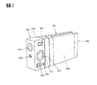
図1ないし図3は、本発明によるデジタルカメラ機能付き携帯用端末機の一実施形態を示す斜視図である。 1 to 3 are perspective views illustrating an embodiment of a portable terminal with a digital camera function according to the present invention.
図示されたように、本発明によるデジタルカメラ機能付き携帯用端末機は、ディスプレイ110が備えられたディスプレイ本体100と、被写体をフォーカシングしてディスプレイ110に現れる前記被写体の像を撮影するカメラモジュール210が備えられるカメラアセンブリ200と、ディスプレイ本体100とカメラアセンブリ200を相互回転可能に結合させる旋回ユニット300と、情報処理機能有し、ディスプレイ本体100に動き可能に装着される端末機本体400と、音声情報を送受信するスピーカーユニット500及びマイクユニット600と、から構成される。
As shown in the figure, a portable terminal with a digital camera function according to the present invention includes a display
端末機本体400及びディスプレイ本体100には、端末機本体400をディスプレイ本体100の長手方向に移動させるスライディングユニットが備えられる。
The
ディスプレイ本体100は、一側に端末機本体400がスライディング可能に装着される装着部121を備え、内部に回路部品が備えられた本体ケーシング120と、該本体ケーシング120に結合されたディスプレイ110と、本体ケーシング120の一側に位置してカメラモジュール210を制御する制御ボタン130と、から構成される。
The display
本体ケーシング120は、所定幅及び長さを有する六面体状に形成され、該六面体の一面に装着部121が形成される。装着部121は、本体ケーシング120の一面に所定深さの段差面を有して形成される。装着部121の深さは、端末機本体400の高さ(または、深さ)と相応し、装着部121の平面形状は、端末機本体400の平面形状と相応するように形成される。
The
ディスプレイ110は、装着部121の反対側に位置するように本体ケーシング120に結合される。ディスプレイ110は、携帯用端末機として使用するときは、各種画像情報などが表示され、被写体を撮影するときは、被写体の像が表示される液晶画面を備える。
The
また、本体ケーシング120の一面には複数の制御ボタン130が備えられる。該制御ボタン130は、ディスプレイ110の側方に位置する。制御ボタン130は、被写体を撮影するとき、被写体のズーム(zoom)、撮影解像度、シャッター速度など、カメラモジュール210を制御する機能を有する。一方、制御ボタン130は、撮影時にカメラモジュール210を制御する用途以外にも、通話の開始及び終了機能、電源のオン/オフ機能及びメニュー機能などに使用される。
A plurality of
カメラアセンブリ200は、所定形状に形成されるカメラケーシング220と、該カメラケーシング220に装着されるカメラモジュール210と、カメラケーシング220に装着される撮影ボタン230と、撮影時に照明を明るくするフラッシュ240と、から構成される。
The
カメラケーシング220は、六面体状に形成され、該六面体の幅及び高さは、ディスプレイ本体100の幅及び高さと同様に形成される。カメラアセンブリ200の一面とディスプレイ本体100の一面が相互接触するように旋回ユニット300によって結合され、相互接触されるカメラアセンブリ200の一面とディスプレイ本体100の一面は、相互同一の形状に形成される。
The
カメラモジュール210は、カメラケーシング220の一面に装着され、カメラモジュール210が装着される面は、ディスプレイ本体100と接触される面と垂直をなす面である。図4に示すように、前記カメラケーシング220の内部に、所定形状を有する結合溝221が形成され、該結合溝221に、カメラモジュール210が挿入されて結合される。結合溝221は、カメラモジュール210と相応する形状に形成され、その結合溝221の側部に位置するカメラケーシング220の面に、カメラモジュール210を構成するレンズ211が位置する貫通穴222が形成され、該貫通穴222に、カメラモジュールのレンズ211を保護する保護レンズ212が結合される。
The
カメラアセンブリ200は、撮影条件によって撮影モードを変更させるモード選択スイッチ250を備え、該モード選択スイッチ250は、カメラケーシング220の一面に装着され、ディスプレイ本体100と接触される面の反対側面に位置する。さらに、モード選択スイッチ250は、ロータリータイプのスイッチであり、使用者がモード選択スイッチ250を回転させることによって、通常撮影、晴れ日の撮影、曇り日の撮影、夜間撮影、野外撮影、室内撮影、接写撮影などに撮影モードを変更させることができる。それぞれの撮影モードは、天気、明暗などの特定条件によって最適のシャッター速度及び露出速度などが入力された状態であり、これによって高品質の撮影が可能になる。
The
モード選択スイッチ250の側部には、撮影ボタン230が位置する。
A
また、カメラアセンブリ200は、照明が相対的に明るいため、ディスプレイ110を通じて被写体を見ることができない場合、その被写体を目で直接見得る直接透視手段260を備える。直接透視手段260は、カメラケーシング220を貫通する通路223及び該通路223に装着される透明レンズ261を含む。透明レンズ261は、通路223を形成するカメラケーシング220の両面にそれぞれ固定結合される。
The
フラッシュ240は、カメラケーシング220に装着され、カメラモジュール210の側部に位置する。
The
また、カメラアセンブリ200は、撮影時に撮影と関連した音声を入力する補助マイクユニット270を備え、該補助マイクユニット270は、フラッシュ240の側部に位置する。
In addition, the
旋回ユニット300は、図5に示すように、ディスプレイ本体100に円筒状に形成された円筒軸310と、該円筒軸310の側方に形成された固定突起320と、円筒軸310の外径より大きい内径及び一定長さを有する円筒部331、該円筒部331の一側に形成されるカム部332、及び円筒部331の他側に形成されるスプリング挿入部333を有し、円筒軸310に回転可能に挿入されると共に、カメラアセンブリ200に固定結合されるカムホルダー330と、カムホルダー330のスプリング挿入部333に挿入されるスプリング340と、カムホルダー330の円筒部331に挿入される円筒軸310に固定結合され、スプリング340を支持固定する固定部材350と、から構成される。
As shown in FIG. 5, the swivel unit 300 includes a
円筒軸310は、カメラアセンブリ200と接触されるディスプレイ本体100の本体ケーシング120の一面に形成され、円筒軸310は、前記一面に対して垂直方向に位置する。円筒軸310が形成された本体ケーシング120の面には円筒軸310の内径と相応する貫通穴(図示せず)が形成され、カメラアセンブリ200の構成部品とディスプレイ本体100の構成部品を連結するワイヤーがその貫通穴を通じて連結される。
The
固定突起320は、円筒軸310の側部に位置するように本体ケーシング120の一面に形成され、固定突起320の断面形状は、多様な形状に形成されることができる。
The fixed
カムホルダー330のカム部332は、円筒部331の端に複数の凹部と凸部を有する波形形態に形成される。前記波形の数によってカムホルダー330が一回に回転する回転角が決定され、その波形数が多くなるにつれて、カムホルダー330が一回に回転する角が小さくなる。
The
固定部材350はナットで、円筒軸310の一端の外周面に前記ナットが結合されるねじ山が形成される。固定部材250の外径は、スプリング340の外径より大きいか、または、同一である。
The fixing
カムホルダー330の円筒部331の外周面両側に、所定厚さ及び長さを有する結合部334がそれぞれ形成され、該結合部334には貫通穴335が貫通形成される。また、ディスプレイ本体100の一面と接触されるカメラアセンブリ200の一面、即ち、カメラアセンブリ200のカメラケーシング220の一面に、結合部334の貫通穴335と相応するねじ孔224がそれぞれ形成される。さらに、ねじ孔224間にカムホルダー330のスプリング挿入部333及び円筒部331が挿入される挿入穴225が貫通形成される。
A
カメラケーシング220は、ディスプレイ本体100と接触される面が別途の分離板によって分離できる。
The surface of the
符号281はねじで、符号282、283はねじ孔である。
旋回ユニット300の結合は、以下のようである。 The coupling of the swivel unit 300 is as follows.
円筒軸310がカムホルダー330の円筒部331に挿入され、カムホルダー330のスプリング挿入部333にスプリング340が挿入され、固定部材350がスプリング340を圧縮した状態で円筒軸310の端に固定結合されることである。このような状態で、カムホルダー330のカム部332は、スプリング340の弾性力によってディスプレイ本体100の一面に密着されると共に、固定突起320に噛み合うようになる。また、カムホルダー330のスプリング挿入部333及び円筒部331がカメラケーシング220の挿入穴225に挿入された状態で、カムホルダー330の結合部334がカメラケーシング220の一面に複数のボルト336によって固定結合される。
The
このように、カメラアセンブリ200は、旋回ユニット300によってディスプレイ本体100と回転可能に結合され、カメラアセンブリ200を回転させると、旋回ユニット300を構成するカムホルダー330のカム部332と固定突起320がスプリング340によって相互密着した状態で、カムホルダー330が回転する。
As described above, the
また、カメラアセンブリ200及びディスプレイ本体100に、カメラアセンブリ200の回転時にその回転状態を感知する感知手段が備えられる。前記感知手段は、カメラアセンブリ200に装着される磁石391と、該磁石391の位置と対面するディスプレイ本体100の一面に装着されて磁石391の磁場を感知する感知センサー392と、感知センサー392によって感知された信号を伝達する信号線393と、から構成される。
In addition, the
前記感知手段の他の変形例として、磁石391は複数であり、該複数の磁石391は、カメラアセンブリ200及びディスプレイ本体100が相対運動する回転 軸を同心軸として円形に所定間隔を置いて配置される。
As another modification of the sensing means, there are a plurality of magnets 391, and the plurality of magnets 391 are arranged at predetermined intervals in a circle with a rotation axis on which the
前記感知手段は、カメラアセンブリ200を回転させることによって、感知センサー392が磁石391の磁場を感知してカメラアセンブリ200の回転数または回転角を認知するようになる。従って、カメラアセンブリ200の回転は、多様な信号入力方式として使用されることができ、また、電源をオン/オフさせる動作信号として使用されることができる。
The sensing means rotates the
スピーカーユニット500は、カメラアセンブリ200側に、カメラモジュール210の反対側に位置するカメラケーシング220の一面に設置される。
The
マイクユニット600は、ディスプレイ本体100側に、制御ボタン130の側部に位置するように本体ケーシング120に設置される。通話時、カメラアセンブリ200に設置されるスピーカーユニット500とディスプレイ本体100に設置されるマイクユニット600が同一面に位置するようになる。
The
端末機本体400は、所定の厚さを有する六面体状に形成される。
The
端末機本体400の一面に情報を入力するキーパッド410が備えられ、その反対側面にバッテリー420が着脱可能に装着される。
A
前記スライディングユニットは、図6に示すように、端末機本体400が装着されるディスプレイ本体100の装着面に所定幅及び長さを有して形成される案内溝122と、その装着面に案内溝122と平行に形成されるラック123と、前記ディスプレイ本体100の装着面に対面する端末機本体400の一面に突出形成されて案内溝122にスライディング可能に挿入される案内突起430と、端末機本体400側に装着されてラック123と噛み合うピニオン440と、ピニオン440を回転させる駆動モータ450と、から構成される。
As shown in FIG. 6, the sliding unit includes a
案内溝122は、ディスプレイ本体100の長手方向に形成され、所定間隔を置いて2つが形成される。また、案内突起430は、案内溝122に挿入時に圧入して挿入され、案内溝122に挿入された状態から抜け出さないようにスリット溝431が形成されたフック形態に形成される。案内突起430は、案内溝122の数と相応するように形成され、その案内溝122の数が2つである場合、案内突起430も2つが形成される。
The
ラック123は、端末機本体400の長手方向に形成され、さらに、2つの案内溝122間に位置する。
The
ディスプレイ本体100の装着部121の装着面に、所定の面積を有する貫通穴124が形成され、ディスプレイ本体100の装着面に対面する端末機本体400の一面に貫通穴124と相応する形状の貫通穴460が形成される。ディスプレイ本体100の構成部品と端末機本体400の構成部品を連結する信号線は、ディスプレイ本体100の貫通穴124と端末機本体400の貫通穴460を通じて連結される。
A through
ピニオン440は、ディスプレイ本体100の貫通穴460内に位置し、端末機本体400とディスプレイ本体100の結合時、ラック123と噛み合うように外部に突出されるように装着される。駆動モータ450は、端末機本体400内部に位置するように装着される。
The
前記スライディングユニットは、駆動モータ450が正回転または逆回転すると、駆動モータ450と連結されたピニオン440が正回転または逆回転するようになる。ピニオン440が正回転または逆回転すると、ピニオン440と噛み合ったラック123が一方向またはその反対方向に直線運動するようになる。ラック123の動きによって端末機本体400とディスプレイ本体100が相互相対運動しながら、端末機本体400がディスプレイ本体100の装着部に入るか、装着部から抜け出るようになる。このとき、案内溝122及び案内突起430によって端末機本体400は直線運動をするようになり、その動く距離が限定される。
In the sliding unit, when the driving
一方、ディスプレイ本体100と端末機本体400が相互結合される結合構造の他の変形例として、端末機本体400は、ディスプレイ本体100の一側にヒンジ手段によってヒンジ結合されることができる。
Meanwhile, as another modification of the coupling structure in which the
符号470は、駆動モータ450を作動させる開閉スイッチである。
以下、本発明によるデジタルカメラ機能付き携帯用端末機の作用効果を説明する。 Hereinafter, operational effects of the portable terminal with a digital camera function according to the present invention will be described.
まず、相手から電話がかかってきた場合、使用者は、制御ボタン130のうち1つを押すことで、相手と連結して電話通話をすることができ、また、相手に電話をかける場合、端末機本体400をスライディングユニットによってディスプレイ本体100から取り出し、その端末機本体400のキーパッド410及び制御ボタン130を利用して相手に電話をかけるようになる。このように、相手の電話を受ける場合または相手に電話をかける場合、スピーカーユニット500、ディスプレイ110及びマイクユニット600は、同一面上に位置し、さらに、このとき、ディスプレイ110は、一般的な携帯用端末機のように画像情報表示機能を遂行する。
First, when a call is received from the other party, the user can connect to the other party by pressing one of the
端末機本体400は、開閉スイッチ470を押すことにより、スライディングユニットによってディスプレイ本体100の装着部121からスライディングされて抜け出るか、その装着部121にまた入るようになる。
The terminal
一方、使用者が自分以外の被写体を撮影する場合、図7に示すように、カメラアセンブリ200を回転させてカメラモジュール210の方向とディスプレイ110の方向を相互反対方向にする。カメラモジュール210は、旋回ユニット300によって回転可能になる。このような状態で、使用者は、カメラモジュール210によってフォーカシングされる被写体の像をディスプレイ110を通じて見ながら所望の被写体の像を撮影するようになる。カメラモジュール210とディスプレイ110の位置は、相互反対である180°の位置以外の角度にして撮影することができる。
On the other hand, when the user photographs a subject other than himself / herself, as shown in FIG. 7, the
一方、明るい場所で被写体を撮影する場合、ディスプレイ110に表示される被写体の像を区別しづらくなり、このとき、直接透視手段260を通じて目で直接被写体を見ながら撮影するようになる。
On the other hand, when photographing a subject in a bright place, it is difficult to distinguish the subject image displayed on the
さらに、使用者が直接自分を撮影する場合、図8に示すように、カメラアセンブリ200を回転させてカメラモジュール210の方向とディスプレイ110の方向を相互同一方向にする。このような状態で、カメラモジュール210によってフォーカシングされる自分の像をディスプレイ110を通じて見ながら所望の自分の像を撮影する。
Further, when the user directly photographs himself / herself, as shown in FIG. 8, the
被写体または使用者自分を撮影する作業は、静止画像だけでなく、動画像を撮影することも可能で、さらに、端末機本体400がディスプレイ本体100の装着部121に位置した状態だけでなく、外部に露出された状態でも可能である。
The operation of photographing the subject or the user himself / herself can capture not only a still image but also a moving image, and not only a state where the
このように本発明は、一般的な携帯用端末機のように相手と電話通話ができるだけでなく、カメラアセンブリ200またはディスプレイ本体100を回転させながら被写体または使用者自分を撮影するようになるので、撮影が簡単で便利になる。反面、従来技術の携帯用端末機は、被写体または使用者自分の撮影時、フォルダ20を開けて撮影するため、撮影が非常に不便であった。
As described above, according to the present invention, not only can a telephone call be made with the other party like a general portable terminal, but also the subject or the user can be photographed while rotating the
また、相対的に照明が明るい場所でディスプレイ110に被写体がよく現れない場合、使用者が直接目で被写体を見ながら撮影可能であるため、撮影の便利性が向上する。
In addition, when the subject does not often appear on the
本発明は、撮影時、ディスプレイ本体100とカメラアセンブリ200が直線形態に位置するので、構造的強度が大きく、さらに、撮影時の構造が一般的なデジタルカメラのような形態を有するため、使用者にとってデジタルカメラを使用する感じを与えるようになる。
In the present invention, since the display
以上のように、本発明の好ましい実施形態を用いて本発明を例示してきたが、本発明は、この実施形態に限定して解釈されるべきものではない。本発明は、特許請求の範囲によってのみその範囲が解釈されるべきであることが理解される。当業者は、本発明の具体的な好ましい実施形態の記載から、本発明の記載および技術常識に基づいて等価な範囲を実施することができることが理解される。本明細書において引用した特許、特許出願および文献は、その内容自体が具体的に本明細書に記載されているのと同様にその内容が本明細書に対する参考として援用されるべきであることが理解される。 As mentioned above, although this invention has been illustrated using preferable embodiment of this invention, this invention should not be limited and limited to this embodiment. It is understood that the scope of the present invention should be construed only by the claims. It is understood that those skilled in the art can implement an equivalent range based on the description of the present invention and the common general technical knowledge from the description of specific preferred embodiments of the present invention. Patents, patent applications, and references cited herein should be incorporated by reference in their entirety as if the contents themselves were specifically described herein. Understood.
100:ディスプレイ本体
110:ディスプレイ
120:本体ケーシング
121:装着部
122:案内溝
123:ラック
124、460:貫通穴
130:制御ボタン
200:カメラアセンブリ
210:カメラモジュール
220:カメラケーシング
223:通路
240:フラッシュ
250:モード選択スイッチ
260:直接透視手段
261:透明レンズ
270:補助マイクユニット
300:旋回ユニット
310:円筒軸
320:固定突起
330:カムホルダー
340:スプリング
350:固定部材
390:磁石
392:感知センサー
393:信号線
400:端末機本体
410:キーパッド
430:案内突起
440:ピニオン
450:駆動モータ
500:スピーカーユニット
600:マイクユニット
DESCRIPTION OF SYMBOLS 100: Display main body 110: Display 120: Main body casing 121: Mounting part 122: Guide groove 123:
Claims (23)
前記携帯用端末機は、
ディスプレイを有しているディスプレイ本体と、
被写体をフォーカシングし、前記ディスプレイにディスプレイされる前記被写体の像を撮影するカメラモジュールを有しているカメラアセンブリと、
前記ディスプレイ本体を前記カメラアセンブリに回転可能に結合する旋回ユニットと、
情報処理機能および無線通信機能を有し、前記ディスプレイ本体に動き可能に装着される端末機本体と、
音声情報を送受信するスピーカーユニットおよびマイクユニットと、
前記カメラアセンブリと前記ディスプレイ本体との間に形成される感知手段であって、前記カメラアセンブリの回転を感知する感知手段と
を備えており、
前記カメラアセンブリは、前記ディスプレイ本体の幅方向に垂直な回転軸のまわりを回転するように構成されており、
前記携帯用端末機に関連した少なくとも1つの機能は、前記回転の感知時または前記回転の感知後に実行され、
前記端末機本体は、前記ディスプレイ本体の長手方向にスライディング可能であるように構成されており、
前記ディスプレイ本体は、
一側に前記端末機本体がスライディング可能に装着される装着部を有し、内部に回路部品を有している本体ケーシングと、
前記本体ケーシングに結合されたディスプレイと、
前記本体ケーシングの一側に形成されていて前記カメラモジュールを制御する制御ボタンと
を備えており、
前記本体ケーシングは、所定幅および長さを有する六面体状に形成されており、
前記六面体状の一面に所定高さの段差面を有する前記装着部が形成されており、
前記装着部の段差面の高さは、前記端末機本体の厚さと同一である、携帯用端末機。 A portable terminal having a digital camera function,
The portable terminal is
A display body having a display;
A camera assembly having a camera module for focusing an object and capturing an image of the object displayed on the display;
A swivel unit that rotatably couples the display body to the camera assembly;
A terminal body having an information processing function and a wireless communication function, and movably mounted on the display body;
A speaker unit and a microphone unit for transmitting and receiving audio information;
Sensing means formed between the camera assembly and the display body, the sensing means for sensing rotation of the camera assembly,
The camera assembly is configured to rotate about a rotation axis perpendicular to a width direction of the display body;
At least one function associated with the portable terminal is performed when the rotation is detected or after the rotation is detected ;
The terminal body is configured to be slidable in the longitudinal direction of the display body,
The display body is
A main body casing having a mounting portion on which the terminal main body is slidably mounted on one side and having a circuit component inside;
A display coupled to the body casing;
A control button which is formed on one side of the main casing and controls the camera module;
With
The main body casing is formed in a hexahedron shape having a predetermined width and length,
The mounting portion having a step surface with a predetermined height is formed on one surface of the hexahedron,
The height of the stepped surface of the mounting part is the same as the thickness of the terminal body .
各種情報を画像で表示し、撮影時に被写体の像を表示する液晶画面を備えている、請求項1に記載の携帯用端末機。 The display is
The portable terminal according to claim 1, further comprising a liquid crystal screen that displays various types of information as images and displays an image of a subject during shooting.
所定形状に形成されるカメラケーシングと、
前記カメラケーシングに装着されるカメラモジュールと、
前記カメラケーシングに装着される撮影ボタンと、
照明用のフラッシュと
を備えている、請求項1に記載の携帯用端末機。 The camera assembly is
A camera casing formed into a predetermined shape;
A camera module mounted on the camera casing;
A shooting button attached to the camera casing;
The portable terminal according to claim 1, further comprising: an illumination flash.
前記カメラケーシングの六面体の幅および高さは、前記ディスプレイ本体の六面体の幅および高さと同一である、請求項4に記載の携帯用端末機。 The camera casing is formed in a hexahedral shape,
The portable terminal according to claim 4 , wherein the hexahedron of the camera casing has the same width and height as the hexahedron of the display body.
前記結合溝に前記カメラモジュールが挿入される、請求項4に記載の携帯用端末機。 A coupling groove having a predetermined shape is formed inside the camera casing,
The portable terminal according to claim 4 , wherein the camera module is inserted into the coupling groove.
前記ディスプレイ本体に円筒状に形成された円筒軸と、
前記円筒軸の側方に形成された固定突起と、
前記円筒軸に回転可能に挿入されるカムホルダーであって、前記カメラアセンブリに固定結合されるカムホルダーと、
前記円筒軸の外径より大きい内径および所定長さを有している円筒部の一側端に形成されるカム部と、
前記円筒部の他側端に形成されるスプリング挿入部と、
前記カムホルダーのスプリング挿入部に挿入されるスプリングと、
前記カムホルダーの円筒部に挿入される円筒軸に固定結合される固定部材であって、前記スプリングを支持固定する固定部材と
を備えている、請求項1に記載の携帯用端末機。 The swivel unit is
A cylindrical shaft formed in a cylindrical shape on the display body;
A fixing protrusion formed on a side of the cylindrical shaft;
A cam holder rotatably inserted into the cylindrical shaft, the cam holder fixedly coupled to the camera assembly;
A cam portion formed at one end of a cylindrical portion having an inner diameter larger than the outer diameter of the cylindrical shaft and a predetermined length;
A spring insertion portion formed at the other end of the cylindrical portion;
A spring inserted into a spring insertion portion of the cam holder;
The portable terminal according to claim 1, further comprising: a fixing member that is fixedly coupled to a cylindrical shaft that is inserted into the cylindrical portion of the cam holder and that supports and fixes the spring.
前記カメラアセンブリに装着される磁石と、
前記磁石の位置と対面する前記ディスプレイ本体の一面に装着され、前記磁石の磁場を感知するセンサーと、
前記センサーによって感知された信号を伝達する信号線と
を備えている、請求項1に記載の携帯用端末機。 The sensing means is
A magnet attached to the camera assembly;
A sensor that is mounted on one surface of the display body facing the position of the magnet and senses the magnetic field of the magnet;
The portable terminal according to claim 1, further comprising: a signal line that transmits a signal sensed by the sensor.
前記端末機本体が装着される前記ディスプレイ本体の装着面に所定幅および長さを有して形成される案内溝と、
前記装着面に前記案内溝と平行に形成されるラックと、
前記ディスプレイ本体の装着面に対面する前記端末機本体の一面に突出形成される案内突起であって、前記案内溝にスライディング可能に挿入される案内突起と、
前記端末機本体に装着されて前記ラックと噛み合うピニオンと、
前記ピニオンを回転させる駆動モータと
を備えている、請求項2に記載の携帯用端末機。 The sliding unit is
A guide groove formed with a predetermined width and length on a mounting surface of the display body on which the terminal body is mounted;
A rack formed on the mounting surface in parallel with the guide groove;
A guide protrusion formed on one surface of the terminal body facing the mounting surface of the display body, the guide protrusion being slidably inserted into the guide groove;
A pinion mounted on the terminal body and meshing with the rack;
The portable terminal according to claim 2, further comprising: a drive motor that rotates the pinion.
2つの案内突起が前記2つの案内溝に挿入されるように形成されている、請求項20に記載の携帯用端末機。 Two guide grooves are formed at a predetermined interval,
21. The portable terminal according to claim 20 , wherein two guide protrusions are formed to be inserted into the two guide grooves.
前記ディスプレイ本体の装着面に対面する前記端末機本体の一面に前記貫通穴に対応する貫通穴が形成されている、請求項20に記載の携帯用端末機。 A through hole having a predetermined area is formed on the mounting surface forming the mounting portion of the display body,
21. The portable terminal according to claim 20 , wherein a through hole corresponding to the through hole is formed on one surface of the terminal main body facing the mounting surface of the display main body.
Applications Claiming Priority (1)
| Application Number | Priority Date | Filing Date | Title |
|---|---|---|---|
| KR1020030097904A KR100608732B1 (en) | 2003-12-26 | 2003-12-26 | Mobile phone convertible into digital camera |
Publications (2)
| Publication Number | Publication Date |
|---|---|
| JP2005198279A JP2005198279A (en) | 2005-07-21 |
| JP4625323B2 true JP4625323B2 (en) | 2011-02-02 |
Family
ID=34545918
Family Applications (1)
| Application Number | Title | Priority Date | Filing Date |
|---|---|---|---|
| JP2004371021A Expired - Fee Related JP4625323B2 (en) | 2003-12-26 | 2004-12-22 | Portable terminal with digital camera function |
Country Status (7)
| Country | Link |
|---|---|
| US (3) | US7636124B2 (en) |
| EP (2) | EP1944950B1 (en) |
| JP (1) | JP4625323B2 (en) |
| KR (1) | KR100608732B1 (en) |
| CN (1) | CN1638403B (en) |
| AT (2) | ATE445963T1 (en) |
| DE (2) | DE602004023660D1 (en) |
Families Citing this family (29)
| Publication number | Priority date | Publication date | Assignee | Title |
|---|---|---|---|---|
| KR100617681B1 (en) * | 2003-04-15 | 2006-08-28 | 삼성전자주식회사 | Method for using rotation key apparatus in wireless terminal |
| FI20050106A (en) * | 2005-01-31 | 2006-08-01 | Elcoteq Se | The mobile communication device |
| US7747004B2 (en) * | 2005-12-22 | 2010-06-29 | Motorola, Inc. | Devices and methods for acoustic usability |
| KR100713433B1 (en) | 2006-01-27 | 2007-05-04 | 삼성전자주식회사 | Self-cradling type mobile phone |
| CN101433062B (en) * | 2006-03-02 | 2011-11-09 | 松下电器产业株式会社 | Portable terminal |
| KR100837433B1 (en) * | 2006-03-06 | 2008-06-12 | 삼성전자주식회사 | Digital device |
| US7672584B2 (en) * | 2006-03-06 | 2010-03-02 | Samsung Electronics Co., Ltd. | Digital device |
| KR100842527B1 (en) * | 2006-04-17 | 2008-07-01 | 삼성전자주식회사 | Hinge apparatus for portable terminal |
| JP4767833B2 (en) * | 2006-12-15 | 2011-09-07 | 富士通株式会社 | Electronic equipment and camera module unit |
| WO2008120706A1 (en) * | 2007-03-30 | 2008-10-09 | Nec Corporation | Sliding structure of portable device, and portable device |
| DE102007031559A1 (en) * | 2007-07-06 | 2009-01-08 | Robert Bosch Gmbh | Portable electronic device |
| TWI330062B (en) * | 2007-12-07 | 2010-09-01 | Htc Corp | Handheld electronic device |
| TWI386008B (en) * | 2008-01-22 | 2013-02-11 | Asustek Comp Inc | Portable electronic device |
| CN101742859A (en) * | 2008-11-20 | 2010-06-16 | 深圳富泰宏精密工业有限公司 | Portable electronic device |
| CN101750698A (en) * | 2008-12-10 | 2010-06-23 | 深圳富泰宏精密工业有限公司 | Lens module and electronic device applying lens module |
| CN101753647A (en) * | 2008-12-22 | 2010-06-23 | 鸿富锦精密工业(深圳)有限公司 | Divide-body mobile phone |
| CN101990011B (en) * | 2009-07-29 | 2013-11-20 | 鸿富锦精密工业(深圳)有限公司 | Portable electronic device |
| TWI387429B (en) * | 2009-08-25 | 2013-02-21 | Wistron Corp | Portable electronic system with a detachable camera module |
| KR101594367B1 (en) * | 2009-09-02 | 2016-02-26 | 엘지전자 주식회사 | A mobile terminal |
| KR101094767B1 (en) | 2010-05-19 | 2011-12-16 | 엘지전자 주식회사 | Mobile device |
| CN102928833B (en) * | 2011-08-10 | 2014-03-19 | 广州三星通信技术研究有限公司 | Anti-collision device and anti-collision method for portable terminal, and portable terminal |
| JP5456082B2 (en) * | 2012-02-03 | 2014-03-26 | キヤノン株式会社 | Electronics |
| CN104238579B (en) * | 2014-09-26 | 2017-05-24 | 广东欧珀移动通信有限公司 | Camera rotation control method applied to mobile terminal and mobile terminal |
| WO2016060342A1 (en) * | 2014-10-16 | 2016-04-21 | Lg Electronics Inc. | Watch type terminal and method for controlling the same |
| WO2016195144A1 (en) * | 2015-06-05 | 2016-12-08 | 엘지전자 주식회사 | Camera module and mobile terminal having same |
| CN104980544B (en) | 2015-07-13 | 2016-10-26 | 广东欧珀移动通信有限公司 | A kind of two ends can the flexible screen mobile terminal of bending |
| CN204859341U (en) * | 2015-08-11 | 2015-12-09 | 深圳遨乐科技有限公司 | FANCAM mini-motion camera with rotating shaft |
| CN110022428B (en) * | 2019-05-24 | 2020-11-06 | 维沃移动通信(杭州)有限公司 | Camera module, terminal equipment and information processing method |
| US11812127B2 (en) * | 2021-10-27 | 2023-11-07 | Dell Products L.P. | Monitor with integrated camera to achieve optimized vertical dimension |
Family Cites Families (33)
| Publication number | Priority date | Publication date | Assignee | Title |
|---|---|---|---|---|
| US4543609A (en) * | 1981-01-19 | 1985-09-24 | Lectrolarm Custom Systems, Inc. | Television surveillance system |
| JP2778876B2 (en) | 1992-07-09 | 1998-07-23 | 極東鋼弦コンクリート振興株式会社 | Guide device for cable installation of cable stayed bridge |
| JPH08294030A (en) | 1995-04-19 | 1996-11-05 | Hitachi Ltd | Video camera integrated with portable telephone set |
| WO1997008888A1 (en) | 1995-08-25 | 1997-03-06 | Hitachi, Ltd. | Recorder equipped with video camera |
| JP3153747B2 (en) | 1995-10-26 | 2001-04-09 | シャープ株式会社 | Wireless image transmission telephone |
| JPH1070485A (en) | 1996-08-27 | 1998-03-10 | Saitama Nippon Denki Kk | Structure for portable telephone set |
| JPH1075287A (en) | 1996-08-30 | 1998-03-17 | Kokusai Electric Co Ltd | Portable video telephone |
| US6295088B1 (en) * | 1997-02-17 | 2001-09-25 | Nikon Corporation | Portable display device |
| JP3988102B2 (en) | 1998-11-06 | 2007-10-10 | 富士フイルム株式会社 | Arm-mounted camera |
| JP2000165718A (en) | 1998-11-30 | 2000-06-16 | Matsushita Electric Ind Co Ltd | Electronic image pickup device |
| JP2001245267A (en) * | 2000-02-28 | 2001-09-07 | Matsushita Electric Ind Co Ltd | Portable information communication terminal unit with video camera |
| JP2002057759A (en) | 2000-08-09 | 2002-02-22 | Nec Saitama Ltd | Foldable portable telephone set |
| JP3751197B2 (en) | 2000-10-02 | 2006-03-01 | 株式会社ケンウッド | Mobile phone |
| JP2002141990A (en) | 2000-10-31 | 2002-05-17 | Kyocera Corp | Portable video telephone set |
| KR100438433B1 (en) | 2001-06-26 | 2004-07-03 | 삼성전자주식회사 | Combination device with portable radiotelephone/personal digital assistant/digital camera assembly |
| JP2003031968A (en) | 2001-07-11 | 2003-01-31 | Kyocera Corp | Electronic terminal apparatus |
| JP3810294B2 (en) | 2001-09-07 | 2006-08-16 | シャープ株式会社 | Mobile phone |
| JP2003110680A (en) | 2001-09-27 | 2003-04-11 | Sanyo Electric Co Ltd | Mobile communication device |
| WO2003030518A1 (en) | 2001-09-28 | 2003-04-10 | Telefonaktiebolaget L. M. Ericsson (Publ) | Mobile communications terminal |
| JP2003120652A (en) | 2001-10-12 | 2003-04-23 | Strawberry Corporation | Hinge device and electronic equipment using hinge device |
| AU2002348838A1 (en) | 2001-11-27 | 2003-06-10 | Koninklijke Philips Electronics N.V. | Electronic portable device |
| KR100450581B1 (en) | 2002-02-28 | 2004-09-30 | 삼성전자주식회사 | Hinge device and portable terminal therewith |
| JP4055116B2 (en) * | 2002-05-07 | 2008-03-05 | 日本電気株式会社 | Mobile phone |
| JP2004056408A (en) | 2002-07-19 | 2004-02-19 | Hitachi Ltd | Cellular phone |
| US6967247B2 (en) * | 2002-07-24 | 2005-11-22 | Isis Pharmaceuticals, Inc. | Deprotection of phosphorus in oligonucleotide synthesis |
| KR100484732B1 (en) * | 2002-11-19 | 2005-04-22 | 삼성전자주식회사 | Sliding type portable wireless terminal |
| JP4101043B2 (en) | 2002-12-11 | 2008-06-11 | キヤノン株式会社 | Image data display system, image data display method, program, storage medium, and imaging apparatus |
| KR100575999B1 (en) | 2003-03-10 | 2006-05-02 | 삼성전자주식회사 | Bar type portable wireless terminal |
| US20040192220A1 (en) * | 2003-03-24 | 2004-09-30 | Inventec Appliances Corp. | Mechanism for switching cellular phone to digital camera |
| FI118668B (en) * | 2003-04-01 | 2008-01-31 | Samsung Electro Mech | Mobile phone and its automatic rotation method |
| FI118669B (en) * | 2003-04-01 | 2008-01-31 | Samsung Electro Mech | Sliding type mobile phone and its sliding method |
| JP4187607B2 (en) | 2003-08-14 | 2008-11-26 | 富士通株式会社 | Mobile wireless communication device |
| US7565183B2 (en) * | 2004-11-15 | 2009-07-21 | Sony Ericsson Mobile Communications Ab | Mobile device with selectable camera position |
-
2003
- 2003-12-26 KR KR1020030097904A patent/KR100608732B1/en not_active IP Right Cessation
-
2004
- 2004-12-21 US US11/016,759 patent/US7636124B2/en not_active Expired - Fee Related
- 2004-12-22 JP JP2004371021A patent/JP4625323B2/en not_active Expired - Fee Related
- 2004-12-23 DE DE602004023660T patent/DE602004023660D1/en active Active
- 2004-12-23 AT AT08006879T patent/ATE445963T1/en not_active IP Right Cessation
- 2004-12-23 EP EP08006879A patent/EP1944950B1/en not_active Not-in-force
- 2004-12-23 EP EP04030681A patent/EP1549029B1/en not_active Not-in-force
- 2004-12-23 AT AT04030681T patent/ATE392083T1/en not_active IP Right Cessation
- 2004-12-23 DE DE602004012954T patent/DE602004012954T2/en active Active
- 2004-12-24 CN CN2004100615411A patent/CN1638403B/en not_active Expired - Fee Related
-
2006
- 2006-12-18 US US11/640,335 patent/US7692717B2/en not_active Expired - Fee Related
- 2006-12-18 US US11/640,333 patent/US7742100B2/en not_active Expired - Fee Related
Also Published As
| Publication number | Publication date |
|---|---|
| DE602004012954D1 (en) | 2008-05-21 |
| CN1638403B (en) | 2010-05-26 |
| US20070097248A1 (en) | 2007-05-03 |
| US7636124B2 (en) | 2009-12-22 |
| US20050140811A1 (en) | 2005-06-30 |
| EP1944950A2 (en) | 2008-07-16 |
| DE602004012954T2 (en) | 2009-05-28 |
| EP1944950B1 (en) | 2009-10-14 |
| US20070099656A1 (en) | 2007-05-03 |
| EP1944950A3 (en) | 2008-09-03 |
| EP1549029A1 (en) | 2005-06-29 |
| CN1638403A (en) | 2005-07-13 |
| ATE392083T1 (en) | 2008-04-15 |
| ATE445963T1 (en) | 2009-10-15 |
| EP1549029B1 (en) | 2008-04-09 |
| DE602004023660D1 (en) | 2009-11-26 |
| US7742100B2 (en) | 2010-06-22 |
| KR20050066596A (en) | 2005-06-30 |
| JP2005198279A (en) | 2005-07-21 |
| KR100608732B1 (en) | 2006-08-04 |
| US7692717B2 (en) | 2010-04-06 |
Similar Documents
| Publication | Publication Date | Title |
|---|---|---|
| JP4625323B2 (en) | Portable terminal with digital camera function | |
| KR100703402B1 (en) | Mobile phone having camera lens module with multi-direction | |
| US7499074B2 (en) | Mobile communication device with enhanced image communication capability | |
| EP1455505A1 (en) | Foldable portable terminal with a camera module | |
| JP2004320742A (en) | Personal digital assistance machine equipped with rotary type camera lens housing | |
| EP1548952A2 (en) | Mobile terminal with camera | |
| KR100560885B1 (en) | Slide type mobile communication terminal with rotating type camera | |
| JP4571780B2 (en) | Mobile terminal equipped with a camera | |
| JP4199576B2 (en) | Foldable mobile terminal | |
| JP2005295228A (en) | Portable electronic equipment | |
| JP4024175B2 (en) | Mobile communication device with imaging unit | |
| CN221351914U (en) | Iris diaphragm, camera module and electronic equipment | |
| KR200346601Y1 (en) | Slide type mobile communication terminal with rotating type camera | |
| JPH08140072A (en) | Terminal equipment for information communication | |
| KR100497466B1 (en) | Mobile phone having dual camera | |
| AU2007201325B2 (en) | Mobile communication device with enhanced image communication capability | |
| KR20050020515A (en) | Camera zooming apparatus for portable terminal | |
| KR100690744B1 (en) | Mobile communication terminal capable close-up photographing | |
| JP2005164622A (en) | Image pickup apparatus | |
| KR20060073291A (en) | Mobile communication terminal equipped with rotary microphone set | |
| TWI421623B (en) | Camera module and portable electronic device using the same | |
| JP2004153407A (en) | Camera attached mobile apparatus | |
| JP2004080318A (en) | Mobile phone with camera | |
| KR20050068969A (en) | Photographing apparatus of mobile phone | |
| KR20050068964A (en) | Zoom camera type mobile phone |
Legal Events
| Date | Code | Title | Description |
|---|---|---|---|
| A977 | Report on retrieval |
Free format text: JAPANESE INTERMEDIATE CODE: A971007 Effective date: 20071004 |
|
| A131 | Notification of reasons for refusal |
Free format text: JAPANESE INTERMEDIATE CODE: A131 Effective date: 20071016 |
|
| A521 | Request for written amendment filed |
Free format text: JAPANESE INTERMEDIATE CODE: A523 Effective date: 20080115 |
|
| A02 | Decision of refusal |
Free format text: JAPANESE INTERMEDIATE CODE: A02 Effective date: 20080509 |
|
| A521 | Request for written amendment filed |
Free format text: JAPANESE INTERMEDIATE CODE: A523 Effective date: 20080902 |
|
| A911 | Transfer to examiner for re-examination before appeal (zenchi) |
Free format text: JAPANESE INTERMEDIATE CODE: A911 Effective date: 20080919 |
|
| A912 | Re-examination (zenchi) completed and case transferred to appeal board |
Free format text: JAPANESE INTERMEDIATE CODE: A912 Effective date: 20081128 |
|
| A01 | Written decision to grant a patent or to grant a registration (utility model) |
Free format text: JAPANESE INTERMEDIATE CODE: A01 |
|
| A61 | First payment of annual fees (during grant procedure) |
Free format text: JAPANESE INTERMEDIATE CODE: A61 Effective date: 20101105 |
|
| R150 | Certificate of patent or registration of utility model |
Free format text: JAPANESE INTERMEDIATE CODE: R150 |
|
| FPAY | Renewal fee payment (event date is renewal date of database) |
Free format text: PAYMENT UNTIL: 20131112 Year of fee payment: 3 |
|
| R250 | Receipt of annual fees |
Free format text: JAPANESE INTERMEDIATE CODE: R250 |
|
| R250 | Receipt of annual fees |
Free format text: JAPANESE INTERMEDIATE CODE: R250 |
|
| LAPS | Cancellation because of no payment of annual fees |