EP1549029A1 - Portable terminal having digital camera function - Google Patents
Portable terminal having digital camera function Download PDFInfo
- Publication number
- EP1549029A1 EP1549029A1 EP04030681A EP04030681A EP1549029A1 EP 1549029 A1 EP1549029 A1 EP 1549029A1 EP 04030681 A EP04030681 A EP 04030681A EP 04030681 A EP04030681 A EP 04030681A EP 1549029 A1 EP1549029 A1 EP 1549029A1
- Authority
- EP
- European Patent Office
- Prior art keywords
- main body
- portable terminal
- unit
- display
- camera
- Prior art date
- Legal status (The legal status is an assumption and is not a legal conclusion. Google has not performed a legal analysis and makes no representation as to the accuracy of the status listed.)
- Granted
Links
Images


Classifications
-
- H—ELECTRICITY
- H04—ELECTRIC COMMUNICATION TECHNIQUE
- H04M—TELEPHONIC COMMUNICATION
- H04M1/00—Substation equipment, e.g. for use by subscribers
- H04M1/02—Constructional features of telephone sets
- H04M1/0202—Portable telephone sets, e.g. cordless phones, mobile phones or bar type handsets
- H04M1/0206—Portable telephones comprising a plurality of mechanically joined movable body parts, e.g. hinged housings
- H04M1/0247—Portable telephones comprising a plurality of mechanically joined movable body parts, e.g. hinged housings comprising more than two body parts
-
- H—ELECTRICITY
- H04—ELECTRIC COMMUNICATION TECHNIQUE
- H04B—TRANSMISSION
- H04B1/00—Details of transmission systems, not covered by a single one of groups H04B3/00 - H04B13/00; Details of transmission systems not characterised by the medium used for transmission
- H04B1/38—Transceivers, i.e. devices in which transmitter and receiver form a structural unit and in which at least one part is used for functions of transmitting and receiving
- H04B1/40—Circuits
-
- H—ELECTRICITY
- H04—ELECTRIC COMMUNICATION TECHNIQUE
- H04M—TELEPHONIC COMMUNICATION
- H04M1/00—Substation equipment, e.g. for use by subscribers
- H04M1/02—Constructional features of telephone sets
- H04M1/0202—Portable telephone sets, e.g. cordless phones, mobile phones or bar type handsets
- H04M1/026—Details of the structure or mounting of specific components
- H04M1/0264—Details of the structure or mounting of specific components for a camera module assembly
-
- H—ELECTRICITY
- H04—ELECTRIC COMMUNICATION TECHNIQUE
- H04N—PICTORIAL COMMUNICATION, e.g. TELEVISION
- H04N23/00—Cameras or camera modules comprising electronic image sensors; Control thereof
- H04N23/50—Constructional details
- H04N23/51—Housings
-
- H—ELECTRICITY
- H04—ELECTRIC COMMUNICATION TECHNIQUE
- H04N—PICTORIAL COMMUNICATION, e.g. TELEVISION
- H04N23/00—Cameras or camera modules comprising electronic image sensors; Control thereof
- H04N23/50—Constructional details
- H04N23/53—Constructional details of electronic viewfinders, e.g. rotatable or detachable
- H04N23/531—Constructional details of electronic viewfinders, e.g. rotatable or detachable being rotatable or detachable
-
- H—ELECTRICITY
- H04—ELECTRIC COMMUNICATION TECHNIQUE
- H04N—PICTORIAL COMMUNICATION, e.g. TELEVISION
- H04N23/00—Cameras or camera modules comprising electronic image sensors; Control thereof
- H04N23/50—Constructional details
- H04N23/55—Optical parts specially adapted for electronic image sensors; Mounting thereof
-
- H—ELECTRICITY
- H04—ELECTRIC COMMUNICATION TECHNIQUE
- H04N—PICTORIAL COMMUNICATION, e.g. TELEVISION
- H04N23/00—Cameras or camera modules comprising electronic image sensors; Control thereof
- H04N23/58—Means for changing the camera field of view without moving the camera body, e.g. nutating or panning of optics or image sensors
-
- H—ELECTRICITY
- H04—ELECTRIC COMMUNICATION TECHNIQUE
- H04M—TELEPHONIC COMMUNICATION
- H04M1/00—Substation equipment, e.g. for use by subscribers
- H04M1/02—Constructional features of telephone sets
- H04M1/0202—Portable telephone sets, e.g. cordless phones, mobile phones or bar type handsets
- H04M1/0206—Portable telephones comprising a plurality of mechanically joined movable body parts, e.g. hinged housings
- H04M1/0208—Portable telephones comprising a plurality of mechanically joined movable body parts, e.g. hinged housings characterized by the relative motions of the body parts
- H04M1/0214—Foldable telephones, i.e. with body parts pivoting to an open position around an axis parallel to the plane they define in closed position
- H04M1/0216—Foldable in one direction, i.e. using a one degree of freedom hinge
- H04M1/0218—The hinge comprising input and/or output user interface means
-
- H—ELECTRICITY
- H04—ELECTRIC COMMUNICATION TECHNIQUE
- H04M—TELEPHONIC COMMUNICATION
- H04M1/00—Substation equipment, e.g. for use by subscribers
- H04M1/02—Constructional features of telephone sets
- H04M1/0202—Portable telephone sets, e.g. cordless phones, mobile phones or bar type handsets
- H04M1/0206—Portable telephones comprising a plurality of mechanically joined movable body parts, e.g. hinged housings
- H04M1/0208—Portable telephones comprising a plurality of mechanically joined movable body parts, e.g. hinged housings characterized by the relative motions of the body parts
- H04M1/0235—Slidable or telescopic telephones, i.e. with a relative translation movement of the body parts; Telephones using a combination of translation and other relative motions of the body parts
- H04M1/0237—Sliding mechanism with one degree of freedom
-
- H—ELECTRICITY
- H04—ELECTRIC COMMUNICATION TECHNIQUE
- H04M—TELEPHONIC COMMUNICATION
- H04M2250/00—Details of telephonic subscriber devices
- H04M2250/20—Details of telephonic subscriber devices including a rotatable camera
-
- H—ELECTRICITY
- H04—ELECTRIC COMMUNICATION TECHNIQUE
- H04N—PICTORIAL COMMUNICATION, e.g. TELEVISION
- H04N7/00—Television systems
- H04N7/14—Systems for two-way working
- H04N7/141—Systems for two-way working between two video terminals, e.g. videophone
- H04N7/142—Constructional details of the terminal equipment, e.g. arrangements of the camera and the display
- H04N2007/145—Handheld terminals
Definitions
- Embodiments of the present invention may relate to a portable terminal. More particularly, embodiments of the present invention may relate to a portable terminal having a digital camera function that allows the user to perform voice communication and to easily photograph a still image or dynamic image of a subject.
- a portable terminal is a communication apparatus that a user may easily carry to perform voice transmission/reception. Due to rapid development of information and communication technologies, portable terminals may have a function of photographing a still image or dynamic image of a subject using a built-in camera, and transmitting or receiving the photographed image to/from another user as well as have functions relating to internet access and/or TV reception. The continuous development of the information and communication technologies may expand the application field of the portable terminal.
- Fig. 1 is a perspective view illustrating a portable terminal having a camera according to an example arrangement. Other arrangements are also possible.
- a portable terminal having the camera may include a main body 10 for inputting information and controlling communication, a folder 20 having a display (not shown) for outputting the information as an image, a hinge coupling device 30 for rotatably coupling the folder 20 to the main body 10, a camera unit 40 rotatably coupled to the hinge coupling device 30, and a battery 50 detachably coupled to the rear surface of the main body 10.
- Fig. 1 also shows an antenna 60, a speaker 70, an auxiliary display 22, and a lens 41 of a camera module.
- the user may open the folder 20 from the main body 10 as shown in Fig. 2.
- the folder 20 may be angularly rotated about an axis by using the hinge coupling device 30 as an axis.
- the folder 20 may have a predetermined angle relative to the main body 10.
- the user may telephone another user or answer the phone in a state in which the user opens the folder 20 from the main body 10.
- the user may open the folder 20 from the main body 10 as shown in Fig. 2.
- the user may position the display 21 of the folder 20 and the lens 41 of the camera unit 40 in a same direction by rotating the camera unit 40.
- the user may adjust his/her image focused by the lens 41 and displayed on the display 21 by controlling the camera unit 40, and photograph himself/herself.
- the user may position the lens 41 of the camera unit 40 and the display 21 of the folder 20 in opposite directions by rotating the camera unit 40.
- the user may watch an image of the subject focused by the lens 41 and displayed on the display 21 by controlling the camera unit 40 and photograph the subject. After photographing the subject, the user may close the folder 20 to return to the original position.
- the user when the user photographs the still image or dynamic image of the subject using the camera unit 40, the user must open the folder 20 to photograph the subject.
- the user may adjust the image of the subject displayed on the display 21 by rotating the camera unit 40. That is, the portable terminal having the above-described camera may be disadvantageous in that the photographing process is complicated.
- the folder 20 and the main body 10 may have a predetermined angle, and thus the display 21 for displaying the image of the subject may be inclined at a predetermined angle. Accordingly, the user cannot easily adjust the image of the subject to a desired composition. While the user is photographing the subject, if the main body 10 or the folder 20 gets an impact, it may be easily broken because the folder 20 is angularly opened from the main body 10.
- Embodiments of the present invention may solve at least the above problems and/or disadvantages and provide at least the advantages described hereinafter.
- Embodiments of the present invention may provide a portable terminal having a digital camera function that allows the user to perform voice communication and/or easily photograph a still image or dynamic image of a subject.
- Embodiments of the present invention may provide a portable terminal having a digital camera function that allows the user to photograph a subject and that improves the structural intensity in a photographing state to prevent damages based on an external impact.
- Embodiments of the present invention may provide a portable terminal having a digital camera function.
- This may include a display main body, a camera assembly, a turning unit, a terminal main body, and a speaker/mike unit (hereafter also called a speaker and a mike unit).
- the display main body may have a display.
- the camera assembly may have a camera module for focusing on a subject and photographing an image of the subject displayed on the display.
- the turning unit may rotatably couple the display main body to the camera assembly.
- the terminal main body may have an information processing function and may be movably mounted on the display main body.
- the speaker unit and the mike unit may transmit and/or receive voice information.
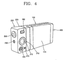
- FIGS. 3 to 5 are perspective views illustrating a portable terminal having a digital camera function according to an example embodiment of the present invention. Other embodiments and configurations are also within the scope of the present invention.
- the portable terminal having the digital camera function may include a display main body 100, a camera assembly 200, a turning unit 300, a terminal main body 400, a speaker unit 500 and a mike unit 600.
- the display main body 100 may have a display 110.
- the camera assembly 200 may have a camera module 210 for focusing on a subject and photographing an image of the subject displayed on the display 110.
- the turning unit 300 may rotatably couple the display main body 100 to the camera assembly 200.
- the terminal main body 400 may have an information processing function and be movably mounted on the display main body 100.
- the speaker unit 500 and the mike unit 600 may transmit and/or receive voice information.
- a sliding unit may move the terminal main body 400 in a lengthwise direction of the display main body 100.
- the sliding unit may be disposed in the terminal main body 400 and the display main body 100.
- the display main body 100 may include a main body casing 120 having a mounting unit 121 on which the terminal main body 400 is slidably positioned at its one side, and having circuit components inside.
- the display 110 may be coupled to the main body casing 120.
- Control buttons 130 may be formed at one side of the main body casing 120 for controlling the camera module 210.
- the main body casing 120 may be formed in a hexahedral shape having a predetermined width and length.
- the mounting unit 121 may be formed on one surface of the hexahedral shape.
- the mounting unit 121 is formed on one surface of the main body casing 120 to have a predetermined depth.
- the depth of the mounting unit 121 may correspond to the height (or depth) of the terminal main body 400, and the flat plate shape of the mounting unit 121 may correspond to the flat plate shape of the terminal main body 400.
- the display 110 may be coupled to the main body casing 120 on an opposite side as the mounting unit 121.
- the display 110 may include a liquid crystal screen for displaying various image information for calls as well as an image (or images) of a subject for photographing.
- the plurality of control buttons 130 may be formed on one surface of the main body casing 120.
- the control buttons 130 may be disposed next to the display 110.
- the control buttons 130 may have control functions for the camera module 210 such as zoom, photographing definition and shutter speed.
- the control buttons 130 may have a call start/end function, a power on/off function and a menu function as well as control functions for the camera module 210 in photographing.
- the camera assembly 200 may include a camera casing 220 formed in a predetermined shape.
- the camera module 210 may mounted on the camera casing 220 and have a photographing button 230 mounted on the camera casing 220 and a flash 240 for lighting.
- the camera casing 220 may be formed in a hexahedral shape.
- the width and height of the hexahedron may be identical (or substantially identical) to those of the display main body 100.
- One surface of the camera assembly 200 and one surface of the display main body 100 may be coupled to contact each other by way of the turning unit 300.
- One surface of the camera assembly 200 and one surface of the display main body 100 contacting each other may be formed in the same shape.
- the camera module 210 may be mounted on one surface of the camera casing 220.
- the surface on which the camera module 210 is mounted may be vertical to the surface contacting the display main body 100.
- a coupling groove 221 may be formed in the camera casing 220 in a predetermined shape and the camera module 210 may be inserted into the coupling groove 221.
- the shape of the coupling groove 221 may correspond to the shape of the camera module 210.
- a through hole 222 may be provided on which a lens 211 composing the camera module 210 is formed on the surface of the camera casing 220 positioned on a side of the coupling groove 221.
- a protecting lens 212 for protecting the lens 211 of the camera module 210 may be coupled to the through hole 222.
- a mode select switch 250 may be formed on the camera assembly 200 for changing a photographing mode based on the photographing conditions.
- the mode select switch 250 may be mounted on one surface of the camera casing 220.
- the surface on which the mode select switch 250 is mounted may be an opposite surface as compared to the surface contacting the display main body 100.
- the mode select switch 250 may be a rotary type switch.
- the user may change the photographing mode into general photographing, clear day photographing, cloudy day photographing, night photographing, outdoor photographing, indoor photographing or close-up photographing, for example, by rotating (or otherwise operating) the mode select switch 250.
- An optimum shutter speed and an optimum exposure speed may be previously set for each of the photographing modes under specific conditions such as weather and brightness. Accordingly, the user may perform high quality photographing.
- the photographing button 230 may be positioned on the side of the mode select switch 250.
- a direct perspective device 260 may be formed on the camera assembly 200 to allow the user to see a subject with a naked eye when he/she is not able to see the subject through the display 110 due to high illumination, for example.
- the direct perspective device 260 may include a passage 223 passing through the camera casing 220, and transparent lenses 261 mounted on the passage 223.
- the transparent lenses 261 may be fixedly coupled to both surfaces of the camera casing 220 composing the passage 223.
- the flash 240 may be mounted on the camera casing 220 on the side of the camera module 210.
- the camera assembly 200 may include an auxiliary mike unit 270 for inputting photographing-related voice when photographing.
- the auxiliary mike unit 270 may be positioned at the side of the flash 240.
- the turning unit 300 may include a cylindrical shaft 310, a fixing protrusion 320, a can holder 330, a can unit 332, a spring insertion unit 333, a spring 340 and a fixing member 350.
- the cylindrical shaft 310 may be formed in a cylindrical shape on the display main body 100.
- the fixing protrusion 320 may be formed at the side of the cylindrical shaft 310.
- the cam holder 330 may be rotatably inserted onto the cylindrical shaft 310 and fixedly coupled to the camera assembly 200.
- the cam unit 332 may be formed at one side end of a cylindrical unit 331 having a larger inside diameter than an outside diameter of the cylindrical shaft 310 and a predetermined length.
- the spring insertion unit 333 may be formed at the other side of the cylindrical unit 331.
- the spring 340 may be inserted into the spring insertion unit 333 of the cam holder 330.
- the fixing member 350 may be fixedly coupled to the cylindrical shaft 310 inserted into the cylindrical unit 331 of the cam holder 330 for fixedly supporting the spring 340.
- the cylindrical shaft 310 may be formed on one surface of the main body casing 120 of the display main body 100 contacting the camera assembly 200.
- the cylindrical shaft 310 may be vertical to the surface.
- a through hole (not shown) corresponding to an inside diameter of the cylindrical shaft 310 may be formed on the surface of the main body casing 120 on which the cylindrical shaft 310 has been formed. Lines connecting the components of the camera assembly 200 to the components of the display main body 100 may be coupled through the through hole.
- the fixing protrusion 320 may be formed on one surface of the main body casing 120 at the side of the cylindrical shaft 310.
- the cam unit 332 of the cam holder 330 may be formed at the end of the cylindrical unit 331 in a waveform shape having a plurality of concave and convex parts.
- An angle of rotating the cam holder 330 may be dependent upon a number of the waveform shapes. When the number of the waveforms increases, the angle of rotating the cam holder 330 may decrease.
- the fixing member 350 may be a nut.
- a thread to which the nut may be coupled may be formed on the outer circumferential surface of the cylindrical shaft 310.
- the outside diameter of the fixing member 250 may be equal to or larger than the outside diameter of the spring 340.
- Coupling units 334 having a predetermined thickness and length may be formed at both sides of the outer circumferential surface of the cylindrical unit 331 of the cam holder 330, respectively, and through holes 335 may be formed on the coupling units 334.
- Screw holes 224 corresponding to the through holes 335 of the coupling units 334 may be formed on one surface of the camera assembly 200 contacting one surface of the display main body 100 (i.e., namely one surface of the camera casing 220 of the camera assembly 200).
- An insertion hole 225 into which the spring insertion unit 333 and the cylindrical unit 331 of the cam holder 330 are inserted may be formed between the screw holes 224.
- Fig. 7 further shows screws 281 and screw holes 282, 283.
- the cylindrical shaft 310 may be inserted into the cylindrical unit 331 of the cam holder 330.
- the spring 340 may be inserted into the spring insertion unit 333 of the cam holder 330 and the fixing member 350 may be fixedly coupled to the end of the cylindrical shaft 310 compressing the spring 340.
- the cam unit 332 of the cam holder 330 may adhere to one surface of the display main body 100 by elasticity of the spring 340 and may be engaged with the fixing protrusion 320.
- the coupling units 334 of the cam holder 330 may be fixedly coupled to one surface of the camera casing 220 by a plurality of bolts 336.
- the camera assembly 200 may be rotatably coupled to the display main body 100 by the turning unit 300.
- the cam unit 332 of the cam holder 330 and the fixing protrusion 320 that form the turning unit 300 may adhere to each other by the spring 340, and the cam holder 330 may be rotated.
- a sensing device may be provided for sensing rotation of the camera assembly 200.
- the sensing device may be formed on the camera assembly 200 and the display main body 100.
- the sensing device may include a magnet 391 mounted on the camera assembly 200, a sensor 392 mounted on one surface of the display main body 100 facing the magnet 391 for sensing a magnetic field of the magnet 391, and a signal line 393 for transmitting a signal sensed by the sensor 392.
- a plurality of magnets 391 may be circularly arranged at predetermined intervals by using a rotation axis for a relative motion of the camera assembly 200 and the display main body 100 as a concentric axis.
- the sensor 392 of the sensing device may sense the magnetic field of the magnet 391 to detect a rotation number or angle of the camera assembly 200.
- Various signal input methods may be used according to rotation of the camera assembly 200, or operation signals for turning on/off power.
- the speaker unit 500 may be installed on the camera assembly 200. More specifically, the speaker unit 500 may be installed on one surface of the camera casing 220 on the opposite side to the camera module 210.
- the mike unit 600 may be installed on the display main body 100. More specifically, the mike unit 600 may be installed on the main body casing 120 at sides of the control buttons 130. When the user talks over the phone, the speaker unit 500 installed on the camera assembly 200 and the mike unit 600 installed on the display main body 100 are positioned on the same surface.
- the terminal main body 400 may be formed in a hexahedral shape having a predetermined thickness.
- a keypad 410 for inputting information may be disposed on one surface of the terminal main body 400 and a battery 420 may be detachably mounted on the opposite surface thereof.
- the sliding unit may include guide grooves 122 formed with a predetermined width and length on the mounting surface of the display main body 100 on which the terminal main body 400 is mounted.
- a rack 123 may be formed on the mounting surface in parallel to the guide grooves 122.
- Guide protrusions 430 may protrude from one surface of the terminal main body 400 facing the mounting surface of the display main body 100, and may be slidably inserted into the guide grooves 122.
- a pinion 440 may be mounted on the terminal main body 400 and engaged with the rack 123.
- a driving motor 450 may rotate the pinion 440.
- the two guide grooves 122 may be formed in a length direction of the display main body 100 at predetermined intervals.
- the guide protrusions 430 may be press-fit into the guide grooves 122 and formed in a hook shape having a slit groove 431 to be separated from the guide grooves 122.
- the number of the guide protrusions 430 may correspond to the number of the guide grooves 122. That is, when two guide grooves 122 are formed, two guide protrusions 430 may be formed.
- the rack 123 may be formed in a length direction of the terminal main body 400 and may be positioned between the two guide grooves 122.
- a through hole 124 having a predetermined area may be formed on the mounting surface (i.e., one surface of the mounting unit 121 of the display main body 100).
- a through hole 460 corresponding to the through hole 124 may be formed on one surface of the terminal main body 400 facing the mounting surface of the display main body 100.
- the signal lines connecting the components of the display main body 100 to the components of the terminal main body 400 may be coupled through the through hole 124 of the display main body 100 and the through hole 460 of the terminal main body 400.
- the pinion 440 may be positioned inside the through hole 460 of the display main body 100, and may be externally protruded to be engaged with the rack 123 when the terminal main body 400 and the display main body 100 are coupled.
- the driving motor 450 may be mounted inside the terminal main body 400.
- the pinion 440 coupled to the driving motor 450 may be rotated in a forward or backward direction.
- the rack 123 engaged with the pinion 440 may perform a linear motion in one direction or in an opposite direction.
- the terminal main body 400 and the display main body 100 perform a relative motion so that the terminal main body 400 can slide to/from the mounting unit 121 of the display main body 100.
- the terminal main body 400 may perform a linear motion within a limited distance based on the guide grooves 122 and the guide protrusions 430.
- the terminal main body 400 may be hinge-coupled to one side of the display main body 100 by a hinge device.
- An open/close switch 470 may be provided for operating the driving motor 450. Operational effects of the portable terminal having a digital camera function in accordance with an example embodiment of the present invention will now be described.
- the user may answer the phone by pressing one of the control buttons 130 and phone another user by pulling the terminal main body 400 from the display main body 100 by the sliding unit and using the keypad 410 and the control buttons 130 of the terminal main body 400.
- the speaker unit 500, the display 110 and the mike unit 600 are positioned on the same surface.
- the display 110 may display image information.
- the terminal main body 400 may slide to/from the mounting unit 121 of the display main body 100 by the sliding unit.
- the user may position the camera module 210 and the display 110 in the opposite directions by rotating the camera assembly 200.
- the camera module 210 may be rotated by the turning unit 300.
- the user may see an image of the subject focused by the camera module 210 and displayed on the display 110, and photograph the wanted image of the subject.
- the camera module 210 and the display 110 may be positioned at different angles such as at an angle of 180° with respect to each other.
- the user may not clearly distinguish the image of the subject displayed on the display 110. Accordingly, the user may photograph the subject seeing the subject with the naked eye through the direct perspective device 260.
- the user may position the camera module 210 and the display 110 in the same direction by rotating the camera assembly 200.
- the user may see his/her image focused by the camera module 210 and displayed on the display 110, and photograph the wanted image.
- the user may photograph a still image or dynamic images of the subject or the user himself/herself when the terminal main body 400 slides to/from the mounting unit 121 of the display main body 100.
- the portable terminal having the digital camera function may allow the user to perform voice communication and photograph the subject or the user himself/herself by rotating the camera assembly 200 or the display main body 100. Therefore, the photographing process may be simplified. Conversely, the portable terminal may not be convenient since the user may have to open the folder 20 to photograph the subject or the user himself/herself.
- the user when the user is not able to clearly see the subject through the display 110 in a lighted place, the user may easily photograph the subject seeing the subject with the naked eye.
- the display main body 100 and the camera assembly 200 may be arranged in a straight line to improve the structural intensity.
- the portable terminal having the digital camera function may allow the user to perform voice communication and to easily photograph still images or dynamic images resulting in the user's satisfaction.
- the portable terminal having the digital camera function shows high structural intensity in the photographing state to prevent damages by an external impact and improve reliability.
- the portable terminal allows the user to freely photograph still images or dynamic images with high satisfaction.
Abstract
Description
- Embodiments of the present invention may relate to a portable terminal. More particularly, embodiments of the present invention may relate to a portable terminal having a digital camera function that allows the user to perform voice communication and to easily photograph a still image or dynamic image of a subject.
- A portable terminal is a communication apparatus that a user may easily carry to perform voice transmission/reception. Due to rapid development of information and communication technologies, portable terminals may have a function of photographing a still image or dynamic image of a subject using a built-in camera, and transmitting or receiving the photographed image to/from another user as well as have functions relating to internet access and/or TV reception. The continuous development of the information and communication technologies may expand the application field of the portable terminal.
- Fig. 1 is a perspective view illustrating a portable terminal having a camera according to an example arrangement. Other arrangements are also possible. As shown in Fig. 1, a portable terminal having the camera may include a
main body 10 for inputting information and controlling communication, afolder 20 having a display (not shown) for outputting the information as an image, ahinge coupling device 30 for rotatably coupling thefolder 20 to themain body 10, acamera unit 40 rotatably coupled to thehinge coupling device 30, and abattery 50 detachably coupled to the rear surface of themain body 10. Fig. 1 also shows anantenna 60, aspeaker 70, anauxiliary display 22, and alens 41 of a camera module. - Operation of the portable terminal having the camera will now be explained. When the user telephones another user or answers the phone, the user may open the
folder 20 from themain body 10 as shown in Fig. 2. Thefolder 20 may be angularly rotated about an axis by using thehinge coupling device 30 as an axis. When thefolder 20 is opened, thefolder 20 may have a predetermined angle relative to themain body 10. The user may telephone another user or answer the phone in a state in which the user opens thefolder 20 from themain body 10. - When the user photographs a still image or dynamic image of a subject by using the camera, the user may open the
folder 20 from themain body 10 as shown in Fig. 2. When the subject is the user (i.e., when the user photographs himself/herself using the camera), the user may position thedisplay 21 of thefolder 20 and thelens 41 of thecamera unit 40 in a same direction by rotating thecamera unit 40. The user may adjust his/her image focused by thelens 41 and displayed on thedisplay 21 by controlling thecamera unit 40, and photograph himself/herself. - On the other hand, when the user photographs another subject, the user may position the
lens 41 of thecamera unit 40 and thedisplay 21 of thefolder 20 in opposite directions by rotating thecamera unit 40. The user may watch an image of the subject focused by thelens 41 and displayed on thedisplay 21 by controlling thecamera unit 40 and photograph the subject. After photographing the subject, the user may close thefolder 20 to return to the original position.
As described above, when the user photographs the still image or dynamic image of the subject using thecamera unit 40, the user must open thefolder 20 to photograph the subject. In addition, the user may adjust the image of the subject displayed on thedisplay 21 by rotating thecamera unit 40. That is, the portable terminal having the above-described camera may be disadvantageous in that the photographing process is complicated. - When the user photographs the subject, the
folder 20 and themain body 10 may have a predetermined angle, and thus thedisplay 21 for displaying the image of the subject may be inclined at a predetermined angle. Accordingly, the user cannot easily adjust the image of the subject to a desired composition. While the user is photographing the subject, if themain body 10 or thefolder 20 gets an impact, it may be easily broken because thefolder 20 is angularly opened from themain body 10. - Embodiments of the present invention may solve at least the above problems and/or disadvantages and provide at least the advantages described hereinafter.
- Embodiments of the present invention may provide a portable terminal having a digital camera function that allows the user to perform voice communication and/or easily photograph a still image or dynamic image of a subject.
- Embodiments of the present invention may provide a portable terminal having a digital camera function that allows the user to photograph a subject and that improves the structural intensity in a photographing state to prevent damages based on an external impact.
- Embodiments of the present invention may provide a portable terminal having a digital camera function. This may include a display main body, a camera assembly, a turning unit, a terminal main body, and a speaker/mike unit (hereafter also called a speaker and a mike unit). The display main body may have a display. The camera assembly may have a camera module for focusing on a subject and photographing an image of the subject displayed on the display. The turning unit may rotatably couple the display main body to the camera assembly. The terminal main body may have an information processing function and may be movably mounted on the display main body. The speaker unit and the mike unit may transmit and/or receive voice information.
- The foregoing and other objects, features, aspects and advantages of the present invention may become more apparent from the following detailed description when taken in conjunction with the accompanying drawings
- The accompanying drawings, which are included to provide a further understanding of the invention and are incorporated in and constitute a part of this specification, illustrate arrangements and embodiments of the present invention and together with the description serve to explain the principles of the invention.
- The following represents brief descriptions of the drawings in which like reference numerals represent like elements and wherein:
- Fig. 1 is a perspective view illustrating a portable terminal having a camera according to an example arrangement;
- Fig. 2 is a perspective view illustrating a using state of the portable terminal having the camera according to an example arrangement;
- Figs. 3 to 5 are perspective views illustrating a portable terminal having a digital camera function according to an example embodiment of the present invention;
- Fig. 6 is a disassembled perspective view illustrating a camera assembly of the portable terminal having the digital camera function according to an example embodiment of the present invention;
- Fig. 7 is a disassembled perspective view illustrating a turning unit of a portable terminal having the digital camera function according to an example embodiment of the present invention;
- Fig. 8 is a disassembled perspective view illustrating a sliding unit of a portable terminal having the digital camera function according to an example embodiment of the present invention; and
- Figs. 9 and 10 are perspective views illustrating a using state of the portable terminal having the digital camera function according to an example embodiment of the present invention.
-
- A portable terminal having a digital camera function in accordance with example embodiments of the present invention will now be described with reference to the accompanying drawings. Figs. 3 to 5 are perspective views illustrating a portable terminal having a digital camera function according to an example embodiment of the present invention. Other embodiments and configurations are also within the scope of the present invention.
- More specifically, and as shown in Figs. 3 to 5, the portable terminal having the digital camera function may include a display
main body 100, acamera assembly 200, aturning unit 300, a terminalmain body 400, aspeaker unit 500 and amike unit 600. The displaymain body 100 may have adisplay 110. Thecamera assembly 200 may have acamera module 210 for focusing on a subject and photographing an image of the subject displayed on thedisplay 110. The turningunit 300 may rotatably couple the displaymain body 100 to thecamera assembly 200. The terminalmain body 400 may have an information processing function and be movably mounted on the displaymain body 100. Thespeaker unit 500 and themike unit 600 may transmit and/or receive voice information. - A sliding unit may move the terminal
main body 400 in a lengthwise direction of the displaymain body 100. The sliding unit may be disposed in the terminalmain body 400 and the displaymain body 100. - The display
main body 100 may include amain body casing 120 having amounting unit 121 on which the terminalmain body 400 is slidably positioned at its one side, and having circuit components inside. Thedisplay 110 may be coupled to themain body casing 120.Control buttons 130 may be formed at one side of the main body casing 120 for controlling thecamera module 210. - The
main body casing 120 may be formed in a hexahedral shape having a predetermined width and length. The mountingunit 121 may be formed on one surface of the hexahedral shape. The mountingunit 121 is formed on one surface of the main body casing 120 to have a predetermined depth. The depth of the mountingunit 121 may correspond to the height (or depth) of the terminalmain body 400, and the flat plate shape of the mountingunit 121 may correspond to the flat plate shape of the terminalmain body 400. - The
display 110 may be coupled to the main body casing 120 on an opposite side as the mountingunit 121. Thedisplay 110 may include a liquid crystal screen for displaying various image information for calls as well as an image (or images) of a subject for photographing. - The plurality of
control buttons 130 may be formed on one surface of themain body casing 120. Thecontrol buttons 130 may be disposed next to thedisplay 110. Thecontrol buttons 130 may have control functions for thecamera module 210 such as zoom, photographing definition and shutter speed. On the other hand, thecontrol buttons 130 may have a call start/end function, a power on/off function and a menu function as well as control functions for thecamera module 210 in photographing. - The
camera assembly 200 may include acamera casing 220 formed in a predetermined shape. Thecamera module 210 may mounted on thecamera casing 220 and have a photographingbutton 230 mounted on thecamera casing 220 and aflash 240 for lighting. - The
camera casing 220 may be formed in a hexahedral shape. The width and height of the hexahedron may be identical (or substantially identical) to those of the displaymain body 100. One surface of thecamera assembly 200 and one surface of the displaymain body 100 may be coupled to contact each other by way of theturning unit 300. One surface of thecamera assembly 200 and one surface of the displaymain body 100 contacting each other may be formed in the same shape. - The
camera module 210 may be mounted on one surface of thecamera casing 220. The surface on which thecamera module 210 is mounted may be vertical to the surface contacting the displaymain body 100. As shown in Fig. 6, acoupling groove 221 may be formed in thecamera casing 220 in a predetermined shape and thecamera module 210 may be inserted into thecoupling groove 221. The shape of thecoupling groove 221 may correspond to the shape of thecamera module 210. A throughhole 222 may be provided on which alens 211 composing thecamera module 210 is formed on the surface of thecamera casing 220 positioned on a side of thecoupling groove 221. A protectinglens 212 for protecting thelens 211 of thecamera module 210 may be coupled to the throughhole 222. - A mode
select switch 250 may be formed on thecamera assembly 200 for changing a photographing mode based on the photographing conditions. The modeselect switch 250 may be mounted on one surface of thecamera casing 220. The surface on which the modeselect switch 250 is mounted may be an opposite surface as compared to the surface contacting the displaymain body 100. The modeselect switch 250 may be a rotary type switch. The user may change the photographing mode into general photographing, clear day photographing, cloudy day photographing, night photographing, outdoor photographing, indoor photographing or close-up photographing, for example, by rotating (or otherwise operating) the modeselect switch 250. An optimum shutter speed and an optimum exposure speed may be previously set for each of the photographing modes under specific conditions such as weather and brightness. Accordingly, the user may perform high quality photographing. The photographingbutton 230 may be positioned on the side of the modeselect switch 250. - A
direct perspective device 260 may be formed on thecamera assembly 200 to allow the user to see a subject with a naked eye when he/she is not able to see the subject through thedisplay 110 due to high illumination, for example. Thedirect perspective device 260 may include apassage 223 passing through thecamera casing 220, andtransparent lenses 261 mounted on thepassage 223. Thetransparent lenses 261 may be fixedly coupled to both surfaces of thecamera casing 220 composing thepassage 223. - The
flash 240 may be mounted on thecamera casing 220 on the side of thecamera module 210. - The
camera assembly 200 may include anauxiliary mike unit 270 for inputting photographing-related voice when photographing. Theauxiliary mike unit 270 may be positioned at the side of theflash 240. - As shown in Fig. 7, the
turning unit 300 may include acylindrical shaft 310, a fixingprotrusion 320, acan holder 330, acan unit 332, aspring insertion unit 333, aspring 340 and a fixingmember 350. Thecylindrical shaft 310 may be formed in a cylindrical shape on the displaymain body 100. The fixingprotrusion 320 may be formed at the side of thecylindrical shaft 310. Thecam holder 330 may be rotatably inserted onto thecylindrical shaft 310 and fixedly coupled to thecamera assembly 200. Thecam unit 332 may be formed at one side end of acylindrical unit 331 having a larger inside diameter than an outside diameter of thecylindrical shaft 310 and a predetermined length. Thespring insertion unit 333 may be formed at the other side of thecylindrical unit 331. Thespring 340 may be inserted into thespring insertion unit 333 of thecam holder 330. The fixingmember 350 may be fixedly coupled to thecylindrical shaft 310 inserted into thecylindrical unit 331 of thecam holder 330 for fixedly supporting thespring 340. - The
cylindrical shaft 310 may be formed on one surface of the main body casing 120 of the displaymain body 100 contacting thecamera assembly 200. Thecylindrical shaft 310 may be vertical to the surface. A through hole (not shown) corresponding to an inside diameter of thecylindrical shaft 310 may be formed on the surface of the main body casing 120 on which thecylindrical shaft 310 has been formed. Lines connecting the components of thecamera assembly 200 to the components of the displaymain body 100 may be coupled through the through hole. - The fixing
protrusion 320 may be formed on one surface of the main body casing 120 at the side of thecylindrical shaft 310. - The
cam unit 332 of thecam holder 330 may be formed at the end of thecylindrical unit 331 in a waveform shape having a plurality of concave and convex parts. An angle of rotating thecam holder 330 may be dependent upon a number of the waveform shapes. When the number of the waveforms increases, the angle of rotating thecam holder 330 may decrease. - The fixing
member 350 may be a nut. A thread to which the nut may be coupled may be formed on the outer circumferential surface of thecylindrical shaft 310. The outside diameter of the fixingmember 250 may be equal to or larger than the outside diameter of thespring 340. - Coupling
units 334 having a predetermined thickness and length may be formed at both sides of the outer circumferential surface of thecylindrical unit 331 of thecam holder 330, respectively, and throughholes 335 may be formed on thecoupling units 334. Screw holes 224 corresponding to the throughholes 335 of thecoupling units 334 may be formed on one surface of thecamera assembly 200 contacting one surface of the display main body 100 (i.e., namely one surface of thecamera casing 220 of the camera assembly 200). Aninsertion hole 225 into which thespring insertion unit 333 and thecylindrical unit 331 of thecam holder 330 are inserted may be formed between the screw holes 224. - The surface of the
camera casing 220 contacting the displaymain body 100 may be separated as an individual plate. Fig. 7 further showsscrews 281 and screwholes - The coupling operation of the
turning unit 300 will now be explained. Thecylindrical shaft 310 may be inserted into thecylindrical unit 331 of thecam holder 330. Thespring 340 may be inserted into thespring insertion unit 333 of thecam holder 330 and the fixingmember 350 may be fixedly coupled to the end of thecylindrical shaft 310 compressing thespring 340. Thecam unit 332 of thecam holder 330 may adhere to one surface of the displaymain body 100 by elasticity of thespring 340 and may be engaged with the fixingprotrusion 320. In a state where thespring insertion unit 333 and thecylindrical unit 331 of thecam holder 330 are inserted into theinsertion hole 225 of thecamera casing 220, thecoupling units 334 of thecam holder 330 may be fixedly coupled to one surface of thecamera casing 220 by a plurality ofbolts 336. - The
camera assembly 200 may be rotatably coupled to the displaymain body 100 by theturning unit 300. When thecamera assembly 200 is rotated, thecam unit 332 of thecam holder 330 and the fixingprotrusion 320 that form theturning unit 300 may adhere to each other by thespring 340, and thecam holder 330 may be rotated. - A sensing device may be provided for sensing rotation of the
camera assembly 200. The sensing device may be formed on thecamera assembly 200 and the displaymain body 100. The sensing device may include amagnet 391 mounted on thecamera assembly 200, asensor 392 mounted on one surface of the displaymain body 100 facing themagnet 391 for sensing a magnetic field of themagnet 391, and asignal line 393 for transmitting a signal sensed by thesensor 392. - As another example of the sensing device, a plurality of
magnets 391 may be circularly arranged at predetermined intervals by using a rotation axis for a relative motion of thecamera assembly 200 and the displaymain body 100 as a concentric axis. - When the
camera assembly 200 is rotated, thesensor 392 of the sensing device may sense the magnetic field of themagnet 391 to detect a rotation number or angle of thecamera assembly 200. Various signal input methods may be used according to rotation of thecamera assembly 200, or operation signals for turning on/off power. - The
speaker unit 500 may be installed on thecamera assembly 200. More specifically, thespeaker unit 500 may be installed on one surface of thecamera casing 220 on the opposite side to thecamera module 210. - The
mike unit 600 may be installed on the displaymain body 100. More specifically, themike unit 600 may be installed on the main body casing 120 at sides of thecontrol buttons 130. When the user talks over the phone, thespeaker unit 500 installed on thecamera assembly 200 and themike unit 600 installed on the displaymain body 100 are positioned on the same surface. - The terminal
main body 400 may be formed in a hexahedral shape having a predetermined thickness. - A
keypad 410 for inputting information may be disposed on one surface of the terminalmain body 400 and abattery 420 may be detachably mounted on the opposite surface thereof. - In Fig. 8, the sliding unit may include guide
grooves 122 formed with a predetermined width and length on the mounting surface of the displaymain body 100 on which the terminalmain body 400 is mounted. Arack 123 may be formed on the mounting surface in parallel to theguide grooves 122.Guide protrusions 430 may protrude from one surface of the terminalmain body 400 facing the mounting surface of the displaymain body 100, and may be slidably inserted into theguide grooves 122. Apinion 440 may be mounted on the terminalmain body 400 and engaged with therack 123. A drivingmotor 450 may rotate thepinion 440. - The two
guide grooves 122 may be formed in a length direction of the displaymain body 100 at predetermined intervals. The guide protrusions 430 may be press-fit into theguide grooves 122 and formed in a hook shape having aslit groove 431 to be separated from theguide grooves 122. The number of theguide protrusions 430 may correspond to the number of theguide grooves 122. That is, when twoguide grooves 122 are formed, twoguide protrusions 430 may be formed. - The
rack 123 may be formed in a length direction of the terminalmain body 400 and may be positioned between the twoguide grooves 122. - A through
hole 124 having a predetermined area may be formed on the mounting surface (i.e., one surface of the mountingunit 121 of the display main body 100). A throughhole 460 corresponding to the throughhole 124 may be formed on one surface of the terminalmain body 400 facing the mounting surface of the displaymain body 100. The signal lines connecting the components of the displaymain body 100 to the components of the terminalmain body 400 may be coupled through the throughhole 124 of the displaymain body 100 and the throughhole 460 of the terminalmain body 400. - The
pinion 440 may be positioned inside the throughhole 460 of the displaymain body 100, and may be externally protruded to be engaged with therack 123 when the terminalmain body 400 and the displaymain body 100 are coupled. The drivingmotor 450 may be mounted inside the terminalmain body 400. - In the sliding unit, when the driving
motor 450 is rotated in a forward or backward direction, thepinion 440 coupled to the drivingmotor 450 may be rotated in a forward or backward direction. When thepinion 440 is rotated in the forward or backward direction, therack 123 engaged with thepinion 440 may perform a linear motion in one direction or in an opposite direction. As the rack moves 123, the terminalmain body 400 and the displaymain body 100 perform a relative motion so that the terminalmain body 400 can slide to/from the mountingunit 121 of the displaymain body 100. The terminalmain body 400 may perform a linear motion within a limited distance based on theguide grooves 122 and theguide protrusions 430. - According to another example of the coupling structure of the display
main body 100 and the terminalmain body 400, the terminalmain body 400 may be hinge-coupled to one side of the displaymain body 100 by a hinge device. - An open/
close switch 470 may be provided for operating the drivingmotor 450. Operational effects of the portable terminal having a digital camera function in accordance with an example embodiment of the present invention will now be described. The user may answer the phone by pressing one of thecontrol buttons 130 and phone another user by pulling the terminalmain body 400 from the displaymain body 100 by the sliding unit and using thekeypad 410 and thecontrol buttons 130 of the terminalmain body 400. When the user answers the phone or phones another user, thespeaker unit 500, thedisplay 110 and themike unit 600 are positioned on the same surface. Thedisplay 110 may display image information. - When the user presses the open/
close switch 470, the terminalmain body 400 may slide to/from the mountingunit 121 of the displaymain body 100 by the sliding unit. - On the other hand, when the user photographs a subject as shown in Fig. 9, the user may position the
camera module 210 and thedisplay 110 in the opposite directions by rotating thecamera assembly 200. Thecamera module 210 may be rotated by theturning unit 300. In this state, the user may see an image of the subject focused by thecamera module 210 and displayed on thedisplay 110, and photograph the wanted image of the subject. Here, thecamera module 210 and thedisplay 110 may be positioned at different angles such as at an angle of 180° with respect to each other. - When the user photographs a subject in a lighted place, the user may not clearly distinguish the image of the subject displayed on the
display 110. Accordingly, the user may photograph the subject seeing the subject with the naked eye through thedirect perspective device 260. - When the user photographs himself/herself, as shown in Fig. 10, the user may position the
camera module 210 and thedisplay 110 in the same direction by rotating thecamera assembly 200. The user may see his/her image focused by thecamera module 210 and displayed on thedisplay 110, and photograph the wanted image. - The user may photograph a still image or dynamic images of the subject or the user himself/herself when the terminal
main body 400 slides to/from the mountingunit 121 of the displaymain body 100. - In embodiments of the present invention, the portable terminal having the digital camera function may allow the user to perform voice communication and photograph the subject or the user himself/herself by rotating the
camera assembly 200 or the displaymain body 100. Therefore, the photographing process may be simplified. Conversely, the portable terminal may not be convenient since the user may have to open thefolder 20 to photograph the subject or the user himself/herself. - In addition, when the user is not able to clearly see the subject through the
display 110 in a lighted place, the user may easily photograph the subject seeing the subject with the naked eye. - Furthermore, the display
main body 100 and thecamera assembly 200 may be arranged in a straight line to improve the structural intensity. The portable terminal having the digital camera function may allow the user to perform voice communication and to easily photograph still images or dynamic images resulting in the user's satisfaction. - When the user photographs still images or dynamic images, the portable terminal having the digital camera function shows high structural intensity in the photographing state to prevent damages by an external impact and improve reliability. As a result, the portable terminal allows the user to freely photograph still images or dynamic images with high satisfaction.
- The foregoing embodiments and advantages are merely exemplary and are not to be construed as limiting the present invention. The present teaching can be readily applied to other types of apparatuses. The description of the present invention is intended to be illustrative, and not to limit the scope of the claims. Many alternatives, modifications, and variations will be apparent to those skilled in the art. In the claims, means-plus-function clauses are intended to cover the structures described herein as performing the recited function and not only structural equivalents but also equivalent structures.
Claims (40)
- A portable terminal having a digital camera function, comprising:a display main body having a display;a camera assembly having a camera module to focus on a subject and to photograph an image of the subject;a turning unit to rotatably couple the display main body to the camera assembly; anda terminal main body having an information processing function, the terminal main body being movably mounted on the display main body.
- The portable terminal of claim 1, wherein the terminal main body is hinge-coupled to one side of the display main body by a hinge device.
- The portable terminal of claim 1, wherein the display main body includes a main body casing having a mounting unit on which the terminal main body is slidably positioned, the main body casing having circuit components, the display coupled to the main body casing, and control buttons provided at one side of the main body casing to control the camera module.
- The portable terminal of claim 3, wherein the main body casing is formed in a substantially hexahedral shape having a predetermined width and length, and the mounting unit is formed on one surface of the hexahedron shape with a step differential surface having a predetermined height.
- The portable terminal of claim 4, wherein the height of the step differential surface of the mounting unit substantially corresponds to a thickness of the terminal main body.
- The portable terminal of claim 1, wherein the display includes a liquid crystal screen to display image information and to display the image of the subject.
- The portable terminal of claim 1, wherein the camera assembly includes a camera casing formed in a predetermined shape and mounted on the camera casing, the camera assembly further including a photographing button on the camera casing, and a flash for lighting.
- The portable terminal of claim 7, wherein the camera casing is formed in a hexahedral shape, and a width and a height of the hexahedron shape substantially corresponds to a width and a height of the display main body.
- The portable terminal of claim 7, wherein the camera assembly includes a mode select switch to change a photographing mode.
- The portable terminal of claim 7, wherein the camera assembly includes a direct perspective device to allow the user to see the subject through the direct perspective device.
- The portable terminal of claim 10, wherein the direct perspective device includes a passage passing through the camera casing, and transparent lenses mounted on the passage.
- The portable terminal of claim 7, wherein the camera assembly includes an auxiliary mike unit to input voice information.
- The portable terminal of claim 7, wherein a coupling groove is formed in the camera casing in a predetermined shape, and the camera module is inserted into the coupling groove.
- The portable terminal of claim 1, wherein the turning unit includes a cylindrical shaft formed in a cylindrical shape on the display main body, a fixing protrusion formed at the side of the cylindrical shaft, a cam holder rotatably inserted onto the cylindrical shaft and fixedly coupled to the camera assembly, a cam unit formed at one side end of a cylindrical unit having a larger inside diameter than an outside diameter of the cylindrical shaft and a predetermined length, a spring insertion unit formed at the other side of the cylindrical unit, a spring inserted into the spring insertion unit of the cam holder, and a fixing member fixedly coupled to the cylindrical shaft inserted into the cylindrical unit of the cam holder to fixedly support the spring.
- The portable terminal of claim 14, wherein the cam unit of the cam holder is formed at the end of the cylindrical unit in a waveform shape having a plurality of concave and convex parts.
- The portable terminal of claim 1, wherein a sensing device to sense rotation of the camera assembly is provided on the camera assembly and the display main body.
- The portable terminal of claim 16, wherein the sensing device includes a magnet mounted on the camera assembly, a sensor mounted on one surface of the display main body facing the magnet and a signal line, the sensor to sense a magnetic field of the magnet, and the signal line to transmit a signal sensed by the sensor.
- The portable terminal of claim 17, wherein a plurality of magnets are arranged at predetermined intervals by using a rotational axis for a relative motion of the camera assembly and the display main body as a concentric axis.
- The portable terminal of claim 1, further comprising a speaker/mike unit installed at least on the camera assembly.
- The portable terminal of claim 19, wherein the speaker/mike unit includes a speaker unit positioned on the camera module.
- The portable terminal of claim 1, wherein the speaker/mike unit includes a mike unit mounted on the display main body.
- The portable terminal of claim 1, wherein a sliding unit to move the terminal main body in a length direction of the display main body is disposed in the terminal main body and the display main body.
- The portable terminal of claim 22, wherein the sliding unit includes guide grooves formed with a predetermined width and length on the mounting surface of the display main body on which the terminal main body is mounted, a rack formed on the mounting surface in parallel to the guide grooves, guide protrusions protruded from one surface of the terminal main body facing the mounting surface of the display main body, and slidably inserted into the guide grooves, a pinion mounted on the terminal main body and engaged with the rack, and a driving motor for rotating the pinion.
- The portable terminal of claim 23, wherein two guide grooves are formed at predetermined intervals, and two guide protrusions are formed to be inserted into the two guide grooves.
- The portable terminal of claim 23, wherein a through hole having a predetermined area is formed on the mounting surface forming the mounting unit of the display main body, and a through hole corresponding to the through hole is formed on one surface of the terminal main body facing the mounting surface of the display main body.
- A portable terminal having a digital camera function, comprising:a camera assembly having a camera module to focus on a subject and photograph an image of the subject;a display main body having a display to display information and to display the image of the subject, the display main body rotatably coupled to the camera assembly; anda terminal main body movably coupled to the display main body.
- The portable terminal of claim 26, wherein the portable terminal includes a sliding unit to control movement of the terminal main body relative to the display main body.
- The portable terminal of claim 26, further comprising a turning unit to rotatably couple the camera assembly to the display main body.
- The portable terminal of claim 28, wherein the turning unit includes at least a cylindrical shaft, a cam holder, a cam unit, a spring insertion unit and a fixing member.
- The portable terminal of claim 28, wherein a sensing device to sense rotation of the camera assembly is provided on the camera assembly and the display main body.
- The portable terminal of claim 30, wherein the sensing device includes a magnet mounted on the camera assembly, a sensor mounted on one surface of the display main body facing the magnet and a signal line, the sensor to sense a magnetic field of the magnet, and the signal line to transmit a signal sensed by the sensor.
- The portable terminal of claim 30, wherein the sensing device includes a plurality of magnets arranged at predetermined intervals by using a rotational axis for a relative motion of the camera assembly and the display main body as a concentric axis.
- A portable telephone comprising:a main body;a slidable body to slide relative to the main body; anda camera unit rotatably coupled to the main body.
- The portable telephone of claim 33, wherein the camera unit includes a direct perspective device to view a subject through the direct perspective device.
- The portable telephone of claim 33, wherein the portable telephone includes a sliding unit to control movement of the terminal main body relative to the main body.
- The portable telephone of claim 33, further comprising a turning unit to rotatably couple the camera assembly to the display main body.
- The portable telephone of claim 36, wherein the turning unit includes at least a cylindrical shaft, a cam holder, a cam unit, a spring insertion unit and a fixing member.
- The portable telephone of claim 36, wherein a sensing device to sense rotation of the camera assembly is provided on at least one of the camera unit and the main body.
- The portable telephone of claim 38, wherein the sensing device includes a magnet, a sensor and a signal line, the sensor to sense a magnetic field of the magnet, and the signal line to transmit a signal sensed by the sensor.
- The portable telephone of claim 38, wherein the sensing device includes a plurality of magnets arranged at predetermined intervals.
Priority Applications (1)
| Application Number | Priority Date | Filing Date | Title |
|---|---|---|---|
| EP08006879A EP1944950B1 (en) | 2003-12-26 | 2004-12-23 | Portable terminal having digital camera function |
Applications Claiming Priority (2)
| Application Number | Priority Date | Filing Date | Title |
|---|---|---|---|
| KR2003097904 | 2003-12-26 | ||
| KR1020030097904A KR100608732B1 (en) | 2003-12-26 | 2003-12-26 | Mobile phone convertible into digital camera |
Related Child Applications (1)
| Application Number | Title | Priority Date | Filing Date |
|---|---|---|---|
| EP08006879A Division EP1944950B1 (en) | 2003-12-26 | 2004-12-23 | Portable terminal having digital camera function |
Publications (2)
| Publication Number | Publication Date |
|---|---|
| EP1549029A1 true EP1549029A1 (en) | 2005-06-29 |
| EP1549029B1 EP1549029B1 (en) | 2008-04-09 |
Family
ID=34545918
Family Applications (2)
| Application Number | Title | Priority Date | Filing Date |
|---|---|---|---|
| EP08006879A Not-in-force EP1944950B1 (en) | 2003-12-26 | 2004-12-23 | Portable terminal having digital camera function |
| EP04030681A Not-in-force EP1549029B1 (en) | 2003-12-26 | 2004-12-23 | Portable terminal having digital camera function |
Family Applications Before (1)
| Application Number | Title | Priority Date | Filing Date |
|---|---|---|---|
| EP08006879A Not-in-force EP1944950B1 (en) | 2003-12-26 | 2004-12-23 | Portable terminal having digital camera function |
Country Status (7)
| Country | Link |
|---|---|
| US (3) | US7636124B2 (en) |
| EP (2) | EP1944950B1 (en) |
| JP (1) | JP4625323B2 (en) |
| KR (1) | KR100608732B1 (en) |
| CN (1) | CN1638403B (en) |
| AT (2) | ATE392083T1 (en) |
| DE (2) | DE602004023660D1 (en) |
Cited By (5)
| Publication number | Priority date | Publication date | Assignee | Title |
|---|---|---|---|---|
| EP1814287A1 (en) | 2006-01-27 | 2007-08-01 | Samsung Electronics Co., Ltd. | Self-cradling type portable terminal |
| EP1848183A1 (en) | 2006-04-17 | 2007-10-24 | Samsung Electronics Co., Ltd. | Hinge device for portable terminal |
| CN102928833A (en) * | 2011-08-10 | 2013-02-13 | 广州三星通信技术研究有限公司 | Anti-collision device and anti-collision method for portable terminal, and portable terminal |
| EP3255867A4 (en) * | 2015-07-13 | 2018-08-15 | Guangdong Oppo Mobile Telecommunications Corp., Ltd | Flexible screen mobile terminal with two bendable ends |
| EP3337155A4 (en) * | 2015-08-11 | 2019-01-23 | CONC Technology Co., Ltd. | Mini sport camera with rotating shaft |
Families Citing this family (24)
| Publication number | Priority date | Publication date | Assignee | Title |
|---|---|---|---|---|
| KR100617681B1 (en) * | 2003-04-15 | 2006-08-28 | 삼성전자주식회사 | Method for using rotation key apparatus in wireless terminal |
| FI20050106A (en) * | 2005-01-31 | 2006-08-01 | Elcoteq Se | The mobile communication device |
| US7747004B2 (en) * | 2005-12-22 | 2010-06-29 | Motorola, Inc. | Devices and methods for acoustic usability |
| US20090029741A1 (en) * | 2006-03-02 | 2009-01-29 | Matsushita Electric Industrial Co., Ltd. | Portable terminal |
| US7672584B2 (en) * | 2006-03-06 | 2010-03-02 | Samsung Electronics Co., Ltd. | Digital device |
| KR100837433B1 (en) * | 2006-03-06 | 2008-06-12 | 삼성전자주식회사 | Digital device |
| JP4767833B2 (en) * | 2006-12-15 | 2011-09-07 | 富士通株式会社 | Electronic equipment and camera module unit |
| WO2008120706A1 (en) * | 2007-03-30 | 2008-10-09 | Nec Corporation | Sliding structure of portable device, and portable device |
| DE102007031559A1 (en) * | 2007-07-06 | 2009-01-08 | Robert Bosch Gmbh | Portable electronic device |
| TWI330062B (en) * | 2007-12-07 | 2010-09-01 | Htc Corp | Handheld electronic device |
| TWI386008B (en) * | 2008-01-22 | 2013-02-11 | Asustek Comp Inc | Portable electronic device |
| CN101742859A (en) * | 2008-11-20 | 2010-06-16 | 深圳富泰宏精密工业有限公司 | Portable electronic device |
| CN101750698A (en) * | 2008-12-10 | 2010-06-23 | 深圳富泰宏精密工业有限公司 | Lens module and electronic device applying lens module |
| CN101753647A (en) * | 2008-12-22 | 2010-06-23 | 鸿富锦精密工业(深圳)有限公司 | Divide-body mobile phone |
| CN101990011B (en) * | 2009-07-29 | 2013-11-20 | 鸿富锦精密工业(深圳)有限公司 | Portable electronic device |
| TWI387429B (en) * | 2009-08-25 | 2013-02-21 | Wistron Corp | Portable electronic system with a detachable camera module |
| KR101594367B1 (en) * | 2009-09-02 | 2016-02-26 | 엘지전자 주식회사 | A mobile terminal |
| KR101094767B1 (en) * | 2010-05-19 | 2011-12-16 | 엘지전자 주식회사 | Mobile device |
| JP5456082B2 (en) * | 2012-02-03 | 2014-03-26 | キヤノン株式会社 | Electronics |
| CN104238579B (en) * | 2014-09-26 | 2017-05-24 | 广东欧珀移动通信有限公司 | Camera rotation control method applied to mobile terminal and mobile terminal |
| WO2016060342A1 (en) * | 2014-10-16 | 2016-04-21 | Lg Electronics Inc. | Watch type terminal and method for controlling the same |
| KR102342558B1 (en) * | 2015-06-05 | 2021-12-23 | 엘지전자 주식회사 | Camera module and mobile terminal having same |
| CN110022428B (en) * | 2019-05-24 | 2020-11-06 | 维沃移动通信(杭州)有限公司 | Camera module, terminal equipment and information processing method |
| US11812127B2 (en) * | 2021-10-27 | 2023-11-07 | Dell Products L.P. | Monitor with integrated camera to achieve optimized vertical dimension |
Citations (3)
| Publication number | Priority date | Publication date | Assignee | Title |
|---|---|---|---|---|
| JP2002111835A (en) * | 2000-10-02 | 2002-04-12 | Kenwood Corp | Movable telephone |
| WO2003030518A1 (en) * | 2001-09-28 | 2003-04-10 | Telefonaktiebolaget L. M. Ericsson (Publ) | Mobile communications terminal |
| WO2003046705A2 (en) * | 2001-11-27 | 2003-06-05 | Koninklijke Philips Electronics N.V. | Electronic portable device |
Family Cites Families (30)
| Publication number | Priority date | Publication date | Assignee | Title |
|---|---|---|---|---|
| US4543609A (en) * | 1981-01-19 | 1985-09-24 | Lectrolarm Custom Systems, Inc. | Television surveillance system |
| JP2778876B2 (en) | 1992-07-09 | 1998-07-23 | 極東鋼弦コンクリート振興株式会社 | Guide device for cable installation of cable stayed bridge |
| JPH08294030A (en) | 1995-04-19 | 1996-11-05 | Hitachi Ltd | Video camera integrated with portable telephone set |
| WO1997008888A1 (en) | 1995-08-25 | 1997-03-06 | Hitachi, Ltd. | Recorder equipped with video camera |
| JP3153747B2 (en) | 1995-10-26 | 2001-04-09 | シャープ株式会社 | Wireless image transmission telephone |
| JPH1070485A (en) | 1996-08-27 | 1998-03-10 | Saitama Nippon Denki Kk | Structure for portable telephone set |
| JPH1075287A (en) | 1996-08-30 | 1998-03-17 | Kokusai Electric Co Ltd | Portable video telephone |
| US6295088B1 (en) * | 1997-02-17 | 2001-09-25 | Nikon Corporation | Portable display device |
| JP3988102B2 (en) | 1998-11-06 | 2007-10-10 | 富士フイルム株式会社 | Arm-mounted camera |
| JP2000165718A (en) | 1998-11-30 | 2000-06-16 | Matsushita Electric Ind Co Ltd | Electronic image pickup device |
| JP2001245267A (en) * | 2000-02-28 | 2001-09-07 | Matsushita Electric Ind Co Ltd | Portable information communication terminal unit with video camera |
| JP2002057759A (en) * | 2000-08-09 | 2002-02-22 | Nec Saitama Ltd | Foldable portable telephone set |
| JP2002141990A (en) | 2000-10-31 | 2002-05-17 | Kyocera Corp | Portable video telephone set |
| KR100438433B1 (en) * | 2001-06-26 | 2004-07-03 | 삼성전자주식회사 | Combination device with portable radiotelephone/personal digital assistant/digital camera assembly |
| JP2003031968A (en) | 2001-07-11 | 2003-01-31 | Kyocera Corp | Electronic terminal apparatus |
| JP3810294B2 (en) | 2001-09-07 | 2006-08-16 | シャープ株式会社 | Mobile phone |
| JP2003110680A (en) | 2001-09-27 | 2003-04-11 | Sanyo Electric Co Ltd | Mobile communication device |
| JP2003120652A (en) | 2001-10-12 | 2003-04-23 | Strawberry Corporation | Hinge device and electronic equipment using hinge device |
| KR100450581B1 (en) * | 2002-02-28 | 2004-09-30 | 삼성전자주식회사 | Hinge device and portable terminal therewith |
| JP4055116B2 (en) * | 2002-05-07 | 2008-03-05 | 日本電気株式会社 | Mobile phone |
| JP2004056408A (en) | 2002-07-19 | 2004-02-19 | Hitachi Ltd | Cellular phone |
| US6967247B2 (en) * | 2002-07-24 | 2005-11-22 | Isis Pharmaceuticals, Inc. | Deprotection of phosphorus in oligonucleotide synthesis |
| KR100484732B1 (en) * | 2002-11-19 | 2005-04-22 | 삼성전자주식회사 | Sliding type portable wireless terminal |
| JP4101043B2 (en) * | 2002-12-11 | 2008-06-11 | キヤノン株式会社 | Image data display system, image data display method, program, storage medium, and imaging apparatus |
| KR100575999B1 (en) * | 2003-03-10 | 2006-05-02 | 삼성전자주식회사 | Bar type portable wireless terminal |
| US20040192220A1 (en) * | 2003-03-24 | 2004-09-30 | Inventec Appliances Corp. | Mechanism for switching cellular phone to digital camera |
| FI118669B (en) * | 2003-04-01 | 2008-01-31 | Samsung Electro Mech | Sliding type mobile phone and its sliding method |
| FI118668B (en) * | 2003-04-01 | 2008-01-31 | Samsung Electro Mech | Mobile phone and its automatic rotation method |
| JP4187607B2 (en) * | 2003-08-14 | 2008-11-26 | 富士通株式会社 | Mobile wireless communication device |
| US7565183B2 (en) * | 2004-11-15 | 2009-07-21 | Sony Ericsson Mobile Communications Ab | Mobile device with selectable camera position |
-
2003
- 2003-12-26 KR KR1020030097904A patent/KR100608732B1/en not_active IP Right Cessation
-
2004
- 2004-12-21 US US11/016,759 patent/US7636124B2/en not_active Expired - Fee Related
- 2004-12-22 JP JP2004371021A patent/JP4625323B2/en not_active Expired - Fee Related
- 2004-12-23 EP EP08006879A patent/EP1944950B1/en not_active Not-in-force
- 2004-12-23 AT AT04030681T patent/ATE392083T1/en not_active IP Right Cessation
- 2004-12-23 DE DE602004023660T patent/DE602004023660D1/en active Active
- 2004-12-23 AT AT08006879T patent/ATE445963T1/en not_active IP Right Cessation
- 2004-12-23 DE DE602004012954T patent/DE602004012954T2/en active Active
- 2004-12-23 EP EP04030681A patent/EP1549029B1/en not_active Not-in-force
- 2004-12-24 CN CN2004100615411A patent/CN1638403B/en not_active Expired - Fee Related
-
2006
- 2006-12-18 US US11/640,333 patent/US7742100B2/en not_active Expired - Fee Related
- 2006-12-18 US US11/640,335 patent/US7692717B2/en not_active Expired - Fee Related
Patent Citations (3)
| Publication number | Priority date | Publication date | Assignee | Title |
|---|---|---|---|---|
| JP2002111835A (en) * | 2000-10-02 | 2002-04-12 | Kenwood Corp | Movable telephone |
| WO2003030518A1 (en) * | 2001-09-28 | 2003-04-10 | Telefonaktiebolaget L. M. Ericsson (Publ) | Mobile communications terminal |
| WO2003046705A2 (en) * | 2001-11-27 | 2003-06-05 | Koninklijke Philips Electronics N.V. | Electronic portable device |
Cited By (10)
| Publication number | Priority date | Publication date | Assignee | Title |
|---|---|---|---|---|
| EP1814287A1 (en) | 2006-01-27 | 2007-08-01 | Samsung Electronics Co., Ltd. | Self-cradling type portable terminal |
| US7702096B2 (en) | 2006-01-27 | 2010-04-20 | Samsung Electronics Co., Ltd | Self-cradling type portable terminal |
| EP1848183A1 (en) | 2006-04-17 | 2007-10-24 | Samsung Electronics Co., Ltd. | Hinge device for portable terminal |
| US8204556B2 (en) | 2006-04-17 | 2012-06-19 | Samsung Electronics Co., Ltd. | Hinge device for portable terminal |
| CN101060547B (en) * | 2006-04-17 | 2013-01-02 | 三星电子株式会社 | Hinge apparatus for portable terminal |
| CN102928833A (en) * | 2011-08-10 | 2013-02-13 | 广州三星通信技术研究有限公司 | Anti-collision device and anti-collision method for portable terminal, and portable terminal |
| CN102928833B (en) * | 2011-08-10 | 2014-03-19 | 广州三星通信技术研究有限公司 | Anti-collision device and anti-collision method for portable terminal, and portable terminal |
| EP3255867A4 (en) * | 2015-07-13 | 2018-08-15 | Guangdong Oppo Mobile Telecommunications Corp., Ltd | Flexible screen mobile terminal with two bendable ends |
| US10341476B2 (en) | 2015-07-13 | 2019-07-02 | Guangdong Oppo Mobile Telecommunications Corp., Ltd. | Mobile terminal |
| EP3337155A4 (en) * | 2015-08-11 | 2019-01-23 | CONC Technology Co., Ltd. | Mini sport camera with rotating shaft |
Also Published As
| Publication number | Publication date |
|---|---|
| KR20050066596A (en) | 2005-06-30 |
| US7692717B2 (en) | 2010-04-06 |
| CN1638403B (en) | 2010-05-26 |
| JP2005198279A (en) | 2005-07-21 |
| EP1944950A2 (en) | 2008-07-16 |
| KR100608732B1 (en) | 2006-08-04 |
| EP1944950B1 (en) | 2009-10-14 |
| CN1638403A (en) | 2005-07-13 |
| US20050140811A1 (en) | 2005-06-30 |
| ATE445963T1 (en) | 2009-10-15 |
| DE602004012954T2 (en) | 2009-05-28 |
| DE602004012954D1 (en) | 2008-05-21 |
| US20070097248A1 (en) | 2007-05-03 |
| US20070099656A1 (en) | 2007-05-03 |
| EP1549029B1 (en) | 2008-04-09 |
| US7742100B2 (en) | 2010-06-22 |
| EP1944950A3 (en) | 2008-09-03 |
| DE602004023660D1 (en) | 2009-11-26 |
| ATE392083T1 (en) | 2008-04-15 |
| JP4625323B2 (en) | 2011-02-02 |
| US7636124B2 (en) | 2009-12-22 |
Similar Documents
| Publication | Publication Date | Title |
|---|---|---|
| US7692717B2 (en) | Portable terminal having digital camera function | |
| US7499074B2 (en) | Mobile communication device with enhanced image communication capability | |
| EP1469656A2 (en) | Mobile phone having a rotational camera lens housing | |
| KR100703402B1 (en) | Mobile phone having camera lens module with multi-direction | |
| EP2206014B1 (en) | Portable electronic device having high-resolution camera with tunable sensor auto focus | |
| KR100593177B1 (en) | Mobile phone camera module with optical zoom | |
| EP1548952A2 (en) | Mobile terminal with camera | |
| CN112383689A (en) | Camera unit and electronic equipment thereof | |
| KR20030089359A (en) | Module of image capturing unit have zoom function | |
| JP2004208176A (en) | Portable terminal device | |
| CN112437214B (en) | Electronic equipment and camera unit thereof | |
| CN220440768U (en) | Image pickup apparatus | |
| AU2007201325B2 (en) | Mobile communication device with enhanced image communication capability | |
| KR100548424B1 (en) | Zoom camera of slide type mobile phone | |
| KR20050020515A (en) | Camera zooming apparatus for portable terminal | |
| KR20050008011A (en) | Camera device for small communication machine | |
| KR100447628B1 (en) | Mobile phone having camera | |
| KR20050028621A (en) | A camera for mobile communication terminal having the function of changeover to proximity photographing | |
| JP2005107073A (en) | Photographing device | |
| TWI421623B (en) | Camera module and portable electronic device using the same | |
| KR20060032489A (en) | Length measuring apparatus for mobile terminal | |
| KR20050041632A (en) | Portable digital radiotelephone | |
| JP2005055714A (en) | Portable terminal device | |
| KR20040077189A (en) | Mobile phone for displaying image captured on camera-lens in sub-LCD | |
| KR20070050198A (en) | Bar type mobile communication terminal |
Legal Events
| Date | Code | Title | Description |
|---|---|---|---|
| PUAI | Public reference made under article 153(3) epc to a published international application that has entered the european phase |
Free format text: ORIGINAL CODE: 0009012 |
|
| 17P | Request for examination filed |
Effective date: 20041223 |
|
| AK | Designated contracting states |
Kind code of ref document: A1 Designated state(s): AT BE BG CH CY CZ DE DK EE ES FI FR GB GR HU IE IS IT LI LT LU MC NL PL PT RO SE SI SK TR |
|
| AX | Request for extension of the european patent |
Extension state: AL BA HR LV MK YU |
|
| AKX | Designation fees paid |
Designated state(s): AT BE BG CH CY CZ DE DK EE ES FI FR GB GR HU IE IS IT LI LT LU MC NL PL PT RO SE SI SK TR |
|
| 17Q | First examination report despatched |
Effective date: 20051114 |
|
| GRAP | Despatch of communication of intention to grant a patent |
Free format text: ORIGINAL CODE: EPIDOSNIGR1 |
|
| GRAS | Grant fee paid |
Free format text: ORIGINAL CODE: EPIDOSNIGR3 |
|
| GRAA | (expected) grant |
Free format text: ORIGINAL CODE: 0009210 |
|
| AK | Designated contracting states |
Kind code of ref document: B1 Designated state(s): AT BE BG CH CY CZ DE DK EE ES FI FR GB GR HU IE IS IT LI LT LU MC NL PL PT RO SE SI SK TR |
|
| REG | Reference to a national code |
Ref country code: GB Ref legal event code: FG4D |
|
| REG | Reference to a national code |
Ref country code: CH Ref legal event code: EP |
|
| REG | Reference to a national code |
Ref country code: IE Ref legal event code: FG4D |
|
| REF | Corresponds to: |
Ref document number: 602004012954 Country of ref document: DE Date of ref document: 20080521 Kind code of ref document: P |
|
| PG25 | Lapsed in a contracting state [announced via postgrant information from national office to epo] |
Ref country code: SI Free format text: LAPSE BECAUSE OF FAILURE TO SUBMIT A TRANSLATION OF THE DESCRIPTION OR TO PAY THE FEE WITHIN THE PRESCRIBED TIME-LIMIT Effective date: 20080409 |
|
| PG25 | Lapsed in a contracting state [announced via postgrant information from national office to epo] |
Ref country code: BG Free format text: LAPSE BECAUSE OF FAILURE TO SUBMIT A TRANSLATION OF THE DESCRIPTION OR TO PAY THE FEE WITHIN THE PRESCRIBED TIME-LIMIT Effective date: 20080709 Ref country code: ES Free format text: LAPSE BECAUSE OF FAILURE TO SUBMIT A TRANSLATION OF THE DESCRIPTION OR TO PAY THE FEE WITHIN THE PRESCRIBED TIME-LIMIT Effective date: 20080720 Ref country code: PT Free format text: LAPSE BECAUSE OF FAILURE TO SUBMIT A TRANSLATION OF THE DESCRIPTION OR TO PAY THE FEE WITHIN THE PRESCRIBED TIME-LIMIT Effective date: 20080909 |
|
| PG25 | Lapsed in a contracting state [announced via postgrant information from national office to epo] |
Ref country code: PL Free format text: LAPSE BECAUSE OF FAILURE TO SUBMIT A TRANSLATION OF THE DESCRIPTION OR TO PAY THE FEE WITHIN THE PRESCRIBED TIME-LIMIT Effective date: 20080409 Ref country code: AT Free format text: LAPSE BECAUSE OF FAILURE TO SUBMIT A TRANSLATION OF THE DESCRIPTION OR TO PAY THE FEE WITHIN THE PRESCRIBED TIME-LIMIT Effective date: 20080409 |
|
| PG25 | Lapsed in a contracting state [announced via postgrant information from national office to epo] |
Ref country code: IS Free format text: LAPSE BECAUSE OF FAILURE TO SUBMIT A TRANSLATION OF THE DESCRIPTION OR TO PAY THE FEE WITHIN THE PRESCRIBED TIME-LIMIT Effective date: 20080809 |
|
| ET | Fr: translation filed | ||
| PG25 | Lapsed in a contracting state [announced via postgrant information from national office to epo] |
Ref country code: LT Free format text: LAPSE BECAUSE OF FAILURE TO SUBMIT A TRANSLATION OF THE DESCRIPTION OR TO PAY THE FEE WITHIN THE PRESCRIBED TIME-LIMIT Effective date: 20080409 Ref country code: CZ Free format text: LAPSE BECAUSE OF FAILURE TO SUBMIT A TRANSLATION OF THE DESCRIPTION OR TO PAY THE FEE WITHIN THE PRESCRIBED TIME-LIMIT Effective date: 20080409 Ref country code: DK Free format text: LAPSE BECAUSE OF FAILURE TO SUBMIT A TRANSLATION OF THE DESCRIPTION OR TO PAY THE FEE WITHIN THE PRESCRIBED TIME-LIMIT Effective date: 20080409 |
|
| PLBE | No opposition filed within time limit |
Free format text: ORIGINAL CODE: 0009261 |
|
| STAA | Information on the status of an ep patent application or granted ep patent |
Free format text: STATUS: NO OPPOSITION FILED WITHIN TIME LIMIT |
|
| PG25 | Lapsed in a contracting state [announced via postgrant information from national office to epo] |
Ref country code: BE Free format text: LAPSE BECAUSE OF FAILURE TO SUBMIT A TRANSLATION OF THE DESCRIPTION OR TO PAY THE FEE WITHIN THE PRESCRIBED TIME-LIMIT Effective date: 20080409 Ref country code: SK Free format text: LAPSE BECAUSE OF FAILURE TO SUBMIT A TRANSLATION OF THE DESCRIPTION OR TO PAY THE FEE WITHIN THE PRESCRIBED TIME-LIMIT Effective date: 20080409 Ref country code: RO Free format text: LAPSE BECAUSE OF FAILURE TO SUBMIT A TRANSLATION OF THE DESCRIPTION OR TO PAY THE FEE WITHIN THE PRESCRIBED TIME-LIMIT Effective date: 20080409 |
|
| 26N | No opposition filed |
Effective date: 20090112 |
|
| PG25 | Lapsed in a contracting state [announced via postgrant information from national office to epo] |
Ref country code: EE Free format text: LAPSE BECAUSE OF FAILURE TO SUBMIT A TRANSLATION OF THE DESCRIPTION OR TO PAY THE FEE WITHIN THE PRESCRIBED TIME-LIMIT Effective date: 20080409 |
|
| PG25 | Lapsed in a contracting state [announced via postgrant information from national office to epo] |
Ref country code: MC Free format text: LAPSE BECAUSE OF NON-PAYMENT OF DUE FEES Effective date: 20081231 |
|
| REG | Reference to a national code |
Ref country code: CH Ref legal event code: PL |
|
| PG25 | Lapsed in a contracting state [announced via postgrant information from national office to epo] |
Ref country code: CY Free format text: LAPSE BECAUSE OF FAILURE TO SUBMIT A TRANSLATION OF THE DESCRIPTION OR TO PAY THE FEE WITHIN THE PRESCRIBED TIME-LIMIT Effective date: 20080409 |
|
| PG25 | Lapsed in a contracting state [announced via postgrant information from national office to epo] |
Ref country code: CH Free format text: LAPSE BECAUSE OF NON-PAYMENT OF DUE FEES Effective date: 20081231 Ref country code: IE Free format text: LAPSE BECAUSE OF NON-PAYMENT OF DUE FEES Effective date: 20081223 Ref country code: LI Free format text: LAPSE BECAUSE OF NON-PAYMENT OF DUE FEES Effective date: 20081231 |
|
| PG25 | Lapsed in a contracting state [announced via postgrant information from national office to epo] |
Ref country code: HU Free format text: LAPSE BECAUSE OF FAILURE TO SUBMIT A TRANSLATION OF THE DESCRIPTION OR TO PAY THE FEE WITHIN THE PRESCRIBED TIME-LIMIT Effective date: 20081010 Ref country code: LU Free format text: LAPSE BECAUSE OF NON-PAYMENT OF DUE FEES Effective date: 20081223 |
|
| PG25 | Lapsed in a contracting state [announced via postgrant information from national office to epo] |
Ref country code: TR Free format text: LAPSE BECAUSE OF FAILURE TO SUBMIT A TRANSLATION OF THE DESCRIPTION OR TO PAY THE FEE WITHIN THE PRESCRIBED TIME-LIMIT Effective date: 20080409 |
|
| PG25 | Lapsed in a contracting state [announced via postgrant information from national office to epo] |
Ref country code: GR Free format text: LAPSE BECAUSE OF FAILURE TO SUBMIT A TRANSLATION OF THE DESCRIPTION OR TO PAY THE FEE WITHIN THE PRESCRIBED TIME-LIMIT Effective date: 20080710 |
|
| REG | Reference to a national code |
Ref country code: FR Ref legal event code: PLFP Year of fee payment: 12 |
|
| PGFP | Annual fee paid to national office [announced via postgrant information from national office to epo] |
Ref country code: IT Payment date: 20151215 Year of fee payment: 12 Ref country code: GB Payment date: 20151111 Year of fee payment: 12 Ref country code: DE Payment date: 20151111 Year of fee payment: 12 Ref country code: FI Payment date: 20151111 Year of fee payment: 12 |
|
| PGFP | Annual fee paid to national office [announced via postgrant information from national office to epo] |
Ref country code: SE Payment date: 20151111 Year of fee payment: 12 Ref country code: FR Payment date: 20151113 Year of fee payment: 12 Ref country code: NL Payment date: 20151112 Year of fee payment: 12 |
|
| REG | Reference to a national code |
Ref country code: DE Ref legal event code: R119 Ref document number: 602004012954 Country of ref document: DE |
|
| PG25 | Lapsed in a contracting state [announced via postgrant information from national office to epo] |
Ref country code: FI Free format text: LAPSE BECAUSE OF NON-PAYMENT OF DUE FEES Effective date: 20161223 |
|
| REG | Reference to a national code |
Ref country code: SE Ref legal event code: EUG |
|
| REG | Reference to a national code |
Ref country code: NL Ref legal event code: MM Effective date: 20170101 |
|
| GBPC | Gb: european patent ceased through non-payment of renewal fee |
Effective date: 20161223 |
|
| PG25 | Lapsed in a contracting state [announced via postgrant information from national office to epo] |
Ref country code: SE Free format text: LAPSE BECAUSE OF NON-PAYMENT OF DUE FEES Effective date: 20161224 |
|
| PG25 | Lapsed in a contracting state [announced via postgrant information from national office to epo] |
Ref country code: NL Free format text: LAPSE BECAUSE OF NON-PAYMENT OF DUE FEES Effective date: 20170101 |
|
| REG | Reference to a national code |
Ref country code: FR Ref legal event code: ST Effective date: 20170831 |
|
| PG25 | Lapsed in a contracting state [announced via postgrant information from national office to epo] |
Ref country code: IT Free format text: LAPSE BECAUSE OF NON-PAYMENT OF DUE FEES Effective date: 20161223 Ref country code: FR Free format text: LAPSE BECAUSE OF NON-PAYMENT OF DUE FEES Effective date: 20170102 |
|
| PG25 | Lapsed in a contracting state [announced via postgrant information from national office to epo] |
Ref country code: DE Free format text: LAPSE BECAUSE OF NON-PAYMENT OF DUE FEES Effective date: 20170701 Ref country code: GB Free format text: LAPSE BECAUSE OF NON-PAYMENT OF DUE FEES Effective date: 20161223 |