JP4625126B2 - Apparatus and system for reducing tire and wheel noise - Google Patents
Apparatus and system for reducing tire and wheel noise Download PDFInfo
- Publication number
- JP4625126B2 JP4625126B2 JP2008518463A JP2008518463A JP4625126B2 JP 4625126 B2 JP4625126 B2 JP 4625126B2 JP 2008518463 A JP2008518463 A JP 2008518463A JP 2008518463 A JP2008518463 A JP 2008518463A JP 4625126 B2 JP4625126 B2 JP 4625126B2
- Authority
- JP
- Japan
- Prior art keywords
- flow resistance
- tire
- wheel
- layers
- resistance barrier
- Prior art date
- Legal status (The legal status is an assumption and is not a legal conclusion. Google has not performed a legal analysis and makes no representation as to the accuracy of the status listed.)
- Expired - Fee Related
Links
Images


Classifications
-
- B—PERFORMING OPERATIONS; TRANSPORTING
- B60—VEHICLES IN GENERAL
- B60C—VEHICLE TYRES; TYRE INFLATION; TYRE CHANGING; CONNECTING VALVES TO INFLATABLE ELASTIC BODIES IN GENERAL; DEVICES OR ARRANGEMENTS RELATED TO TYRES
- B60C5/00—Inflatable pneumatic tyres or inner tubes
- B60C5/20—Inflatable pneumatic tyres or inner tubes having multiple separate inflatable chambers
-
- B—PERFORMING OPERATIONS; TRANSPORTING
- B60—VEHICLES IN GENERAL
- B60C—VEHICLE TYRES; TYRE INFLATION; TYRE CHANGING; CONNECTING VALVES TO INFLATABLE ELASTIC BODIES IN GENERAL; DEVICES OR ARRANGEMENTS RELATED TO TYRES
- B60C19/00—Tyre parts or constructions not otherwise provided for
- B60C19/002—Noise damping elements provided in the tyre structure or attached thereto, e.g. in the tyre interior
-
- B—PERFORMING OPERATIONS; TRANSPORTING
- B60—VEHICLES IN GENERAL
- B60C—VEHICLE TYRES; TYRE INFLATION; TYRE CHANGING; CONNECTING VALVES TO INFLATABLE ELASTIC BODIES IN GENERAL; DEVICES OR ARRANGEMENTS RELATED TO TYRES
- B60C5/00—Inflatable pneumatic tyres or inner tubes
-
- Y—GENERAL TAGGING OF NEW TECHNOLOGICAL DEVELOPMENTS; GENERAL TAGGING OF CROSS-SECTIONAL TECHNOLOGIES SPANNING OVER SEVERAL SECTIONS OF THE IPC; TECHNICAL SUBJECTS COVERED BY FORMER USPC CROSS-REFERENCE ART COLLECTIONS [XRACs] AND DIGESTS
- Y10—TECHNICAL SUBJECTS COVERED BY FORMER USPC
- Y10T—TECHNICAL SUBJECTS COVERED BY FORMER US CLASSIFICATION
- Y10T152/00—Resilient tires and wheels
- Y10T152/10—Tires, resilient
- Y10T152/10495—Pneumatic tire or inner tube
- Y10T152/10522—Multiple chamber
- Y10T152/10531—Cylinder and piston
- Y10T152/1054—Mutually free walls
Description
本特許出願は、2005年6月24日出願の「タイヤおよびホイールの騒音を吸収する装置およびシステム」と題された、米国仮特許出願第60/694018号に対する優先権を、35U.S.C.セクション119に基づいて主張する。上に特定する優先出願の開示の一切は、参照によって全面的に本明細書に組み込まれる。 This patent application claims priority to US Provisional Patent Application No. 60 / 694,018 entitled “Apparatus and System for Absorbing Tire and Wheel Noise” filed on June 24, 2005. S. C. Claim based on section 119. The entire disclosure of the priority application identified above is fully incorporated herein by reference.
本発明は、一般にタイヤおよびホイールに起因する車両騒音を低減することに関する。詳細には、本発明は、タイヤおよびタイヤが組み付けられるホイールによって作り出される内部空気室内に配設される減音装置に関する。 The present invention relates generally to reducing vehicle noise due to tires and wheels. Specifically, the present invention relates to a sound reduction device disposed in an internal air chamber created by a tire and a wheel on which the tire is assembled.
自動車のタイヤは、路面に接触するときに、大きな騒音を発生する。一部の車両においては、25mphを超える速度では、タイヤ騒音は、自動車のその他の騒音源すべてを合わせたよりも大きくなる可能性がある。そのため、自動車およびタイヤの製造者は、毎年、タイヤ騒音を低減するための研究開発に膨大な資源を注ぎ込んでいる。 Automobile tires generate significant noise when they come into contact with the road surface. In some vehicles, at speeds above 25 mph, tire noise can be greater than the sum of all other noise sources in the car. As a result, automobile and tire manufacturers annually invest vast resources in research and development to reduce tire noise.
タイヤ騒音は、数多くの源から生じる。例えば、タイヤ騒音は、(1)タイヤと路面の接触によってもたらされるタイヤの変形による、タイヤの内部空気室の加振によって発生する低周波数の衝撃波、(2)道路と接触したときのタイヤのたわみによってもたらされる空気室の加振による、低周波数のタイヤ構造のうなり音、(3)トレッドと路面との間に一時的に閉じ込められる空気によって生じる、高周波数のトレッド外側の空気圧縮、および(4)タイヤと路面との間の摩擦による、高周波数の接触こすれ合いによって発生する。 Tire noise comes from a number of sources. For example, the tire noise includes (1) a low-frequency shock wave generated by vibration of the internal air chamber of the tire due to deformation of the tire caused by contact between the tire and the road surface, and (2) tire deflection when in contact with the road. (3) Air compression outside the high-frequency tread caused by air temporarily trapped between the tread and the road surface, and (4 ) Generated by high frequency contact rubbing due to friction between tire and road surface.
トレッドの空気圧縮騒音の一部は、避けることのできないものである。例えば、トレッドの空気圧縮は、道路との接触時に水と空気を圧縮し、次にトレッドが離れるときにその混合物を膨張させることによって、トレッドの接触面から水を排除する作用を果たす。さらに、タイヤの接地は、路面との間で摩擦および騒音を生じる有限のものである以上、接触こすれ合い騒音の一部も、避けることのできないものである。 Some of the tread air compression noise is inevitable. For example, tread air compression serves to remove water from the contact surface of the tread by compressing water and air upon contact with the road and then expanding the mixture as the tread leaves. Further, since the ground contact of the tire is a finite one that generates friction and noise with the road surface, part of the contact rubbing noise is unavoidable.
タイヤの変形による衝撃波エネルギーは、トレッドの接触面から、タイヤおよびタイヤが取り付けられているホイールによって形成されるタイヤ内部の空気室に伝達される。タイヤ内部の空気室に伝達されたエネルギーは、タイヤのうなり音およびホイールへの騒音の結合によってのみ消散される。こうしたタイヤのうなり音および騒音結合には、タイヤ騒音の全体量の相当部分が含まれる。 Shock wave energy due to deformation of the tire is transmitted from the contact surface of the tread to an air chamber inside the tire formed by the tire and the wheel to which the tire is attached. The energy transferred to the air chamber inside the tire is dissipated only by the combination of tire beating and noise to the wheel. Such tire beat and noise coupling includes a substantial portion of the total amount of tire noise.
タイヤ騒音低減のための従来の方法には、いくつかの欠陥がある。とりわけ、それらの方法は、タイヤ騒音を発生させる衝撃波に付随した低周波数エネルギー(例えば、800Hz未満)を効果的に吸収しない。タイヤは、かなりの低周波数エネルギーを発生させるため、効果的なタイヤ騒音吸収装置は、そうした低周波数エネルギーによって発生する騒音を低減するものであるべきである。しかし、従来の方法では、そのような騒音が十分に低減されない。また、低周波数騒音は、トレッドの空気圧縮およびタイヤのこすれ合いによって生じる知覚される高周波数騒音を増大させる。そのため、従来の方法は、低周波数エネルギー騒音を低減することができないために、知覚される高周波数タイヤ騒音を低減することができない。その他の欠陥としては、従来の方法を用いる場合のホイールへのタイヤの組み付けが困難であること、車両の動作中に従来の方法が故障した場合に、損傷の可能性があること、従来の方法の効率が悪いことが挙げられる。 There are several deficiencies in conventional methods for reducing tire noise. Among other things, these methods do not effectively absorb the low frequency energy (eg, less than 800 Hz) associated with shock waves that generate tire noise. Since tires generate significant low frequency energy, an effective tire noise absorber should reduce the noise generated by such low frequency energy. However, the conventional method does not sufficiently reduce such noise. Low frequency noise also increases perceived high frequency noise caused by tread air compression and tire rubbing. Therefore, conventional methods cannot reduce perceived high frequency tire noise because low frequency energy noise cannot be reduced. Other defects include the difficulty in assembling the tires on the wheels when using the conventional method, the possibility of damage if the conventional method fails during vehicle operation, and the conventional method. Is inefficient.
低周波数騒音を吸収するための従来の方法は存在する。しかし、そうした従来の方法は、タイヤ空気室のような小さな内部空気室に対しては実用的でない。そうした低周波数騒音吸収のための従来の方法は、タイヤ空気室には大きすぎ、タイヤを膨らませる妨げになり、効果的でなく、かつ/またはタイヤと組み合わせて使用したときに、安全上の問題を生じる。 There are conventional methods for absorbing low frequency noise. However, such conventional methods are not practical for small internal air chambers such as tire air chambers. Such conventional methods for low frequency noise absorption are too large for the tire air chamber, prevent the tire from inflating, are not effective and / or are a safety issue when used in combination with a tire. Produce.
そのため、当技術においては、タイヤおよびタイヤを組み付けるホイールによって、またはそれらの内部で発生する騒音の低減に対する必要性が存在する。詳細には、当技術においては、タイヤの内部空気室内におけるエネルギーの吸収または低減による、タイヤ騒音低減に対する必要性が存在する。より詳細には、タイヤの空気室のような小さな内部空気室内で機能して、低周波数エネルギーを吸収または低減することができるタイヤ騒音吸収/低減装置に対する必要性が存在する。 Therefore, there is a need in the art for the reduction of noise generated by or within the tire and the wheel on which the tire is assembled. In particular, there is a need in the art for tire noise reduction by absorbing or reducing energy in the tire's internal air chamber. More particularly, a need exists for a tire noise absorption / reduction device that can function in a small interior air chamber, such as a tire air chamber, to absorb or reduce low frequency energy.
タイヤ騒音低減のための装置は、タイヤ騒音を発生させる低周波数エネルギーを吸収し、低減することができる。この装置は、空気流抵抗バリアを持つ容器の加圧と減圧を交互に行うことによって、音響衝撃波を吸収することができる。空気流抵抗バリアは、容器に出入りする圧力流を減衰することによって、そのバリアを通過する衝撃波を減衰する。さらに、容器の流れ抵抗要素の摩擦は、音のエネルギーを熱に変換し、それによって音を減衰する。さらに、ハイブリッド装置は、空気流抵抗キャビティの吸収体の要素、および摩擦吸収体の要素を有することができる。 An apparatus for reducing tire noise can absorb and reduce low frequency energy that generates tire noise. This device can absorb acoustic shock waves by alternately pressurizing and depressurizing a container having an airflow resistance barrier. The airflow resistance barrier attenuates shock waves passing through the barrier by attenuating the pressure flow entering and exiting the container. Further, the friction of the container flow resistance element converts the sound energy into heat, thereby attenuating the sound. Further, the hybrid device can have an airflow resistance cavity absorber element and a friction absorber element.
1つの態様では、タイヤ騒音吸収装置は、各層に複数の開口を持つ空気流抵抗材料の複数の層を備えることができる。複数の層は、層の開口を、隣接する層の重なり合う部分に関してずらして組み立てられることができる。ずらされた開口は、タイヤが停止しかつ層がたるんでいるときに、空気が層を通り、それによってタイヤが完全に膨らむことを可能にする。重なり合う層は、ホイールに結合されるか、または直接タイヤに結合されることによって、重なり合う要素のループを形成することができる。自動車が動き始め、タイヤが回転し出すと、遠心力が、開口の空気通路を密封し、かつホイールと布地層との間に空気流抵抗キャビティを形成するように、重なり合う層を外にかつともに押しやる。詳細には、内側の層は、外に押しやられて外側の層に押し付けられ、内側の層の開口は、外側の層によって密封され、かつ外側の層の開口は、内側の層によって密封される。層は、層のタイヤ側(外側)と層のホイール側(内側)との間の空気の流れを制限し、それによって、空気が層を通り抜けるときの低周波数エネルギー騒音を吸収する。 In one aspect, the tire noise absorbing device can comprise multiple layers of air flow resistance material with multiple openings in each layer. The plurality of layers can be assembled with the layer openings offset relative to the overlapping portions of adjacent layers. The staggered opening allows air to pass through the layers when the tire is stopped and the layers are sagging, thereby allowing the tires to fully inflate. The overlapping layers can be bonded to the wheel or directly to the tire to form a loop of overlapping elements. When the car begins to move and the tires start to rotate, the centrifugal force seals the air passage in the opening and creates an airflow resistance cavity between the wheel and the fabric layer, with the overlapping layers out and together. Push it. Specifically, the inner layer is pushed out and pressed against the outer layer, the inner layer opening is sealed by the outer layer, and the outer layer opening is sealed by the inner layer. . The layer restricts the flow of air between the tire side (outside) of the layer and the wheel side (inside) of the layer, thereby absorbing low frequency energy noise as the air passes through the layer.
さらに別の実施形態では、層は、互いに摺動することができ、低周波数衝撃波によって変位されたときに摩擦を生じる。結果として生じる摩擦は、摩擦で生じる熱によってその種の衝撃波を消散させることで、低周波数エネルギー騒音をさらに吸収することができる。 In yet another embodiment, the layers can slide on each other and produce friction when displaced by a low frequency shock wave. The resulting friction can further absorb low frequency energy noise by dissipating such shock waves by the heat generated by the friction.
低周波数エネルギーの吸収を増大させることは、トレッドのデザインやタイヤの接地性を損なうことなしに、知覚される高周波数タイヤ騒音を低減することもできる。その構造は、既存のタイヤに容易に適合できるものであり、既存のホイールに、またはタイヤに、製造工程中に、または製造工程の後で組み付けられることができる。 Increasing absorption of low frequency energy can also reduce perceived high frequency tire noise without compromising tread design or tire ground contact. The structure is easily adaptable to existing tires and can be assembled to existing wheels or to tires during the manufacturing process or after the manufacturing process.
その他の態様は、装置をホイールまたはタイヤに取り付ける位置および結合手段の変形を含む。例えば、装置は、ホイール上の中心に当たる位置で結合されることができ、または様々な形状の流れ抵抗キャビティを提供する様々な輪郭で結合されることができる。さらに別の態様には、流れ抵抗キャビティを作り出すために、重なり合うまたはインターロッキング端部を持つ複数の要素を含む。それらの要素は、遠心力によって外に押しやられ、重なり合うまたはインターロッキング部分が、空気の流れに抵抗する装置を作り出すようにともに動くときにキャビティを作り出す。さらに、重なり合った部分は、衝撃波によって変位されたときに摩擦を生じ、それによってさらに低周波数騒音を吸収することができる。さらに他の態様は、ホイールまたはタイヤの周囲に2つ以上の流れ抵抗要素を積層することによって、複数の流れ抵抗空気キャビティを作り出すことを含む。こうした複数の流れ抵抗空気キャビティは、衝撃波を吸収することができ、騒音低減を改善することができる。さらに別の態様は、ホイールまたはタイヤ上に配設され、それによって単一の流れ抵抗キャビティを作り出す、管状、三日月形の、または湾曲した要素を含む。こうした管状の要素は、ホイールの周囲に複数の流れ抵抗キャビティを作り出すために複数の部分で使用されることもできる。 Other aspects include variations in location and coupling means for attaching the device to the wheel or tire. For example, the devices can be coupled at a location that hits the center on the wheel, or can be coupled in various profiles that provide various shapes of flow resistant cavities. Yet another aspect includes multiple elements with overlapping or interlocking ends to create a flow resistant cavity. Those elements are pushed out by centrifugal force, creating a cavity when the overlapping or interlocking parts move together to create a device that resists air flow. In addition, the overlapped portion can cause friction when displaced by a shock wave, thereby further absorbing low frequency noise. Yet another aspect includes creating a plurality of flow resistant air cavities by laminating two or more flow resistant elements around a wheel or tire. Such multiple flow resistant air cavities can absorb shock waves and improve noise reduction. Yet another aspect includes a tubular, crescent or curved element disposed on a wheel or tire, thereby creating a single flow resistance cavity. Such tubular elements can also be used in multiple parts to create multiple flow resistant cavities around the wheel.
上に説明した装置は、様々な方法でホイールまたはタイヤに結合されることができる。例えば、流れ抵抗キャビティを作り出す要素は、ホイールもしくはタイヤの溝もしくはフランジにクリンプされることによって、またはホイールもしくはタイヤに溶着され、成形され、もしくは織られることによって、接着剤またはクランプによってホイールもしくはタイヤに結合されることができる。 The device described above can be coupled to the wheel or tire in various ways. For example, an element that creates a flow resistant cavity can be bonded to the wheel or tire by an adhesive or clamp, by being crimped into a groove or flange of the wheel or tire, or by being welded , molded, or woven to the wheel or tire. Can be combined.
図1Aから図13までを参照しながら、いくつかの例示的実施形態について以下に説明する。図中、同じ参照符号は同様の要素を表す。 Several exemplary embodiments are described below with reference to FIGS. 1A-13. In the figures, the same reference numerals represent similar elements.
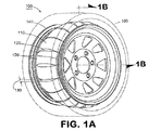
図1Aは、例示的実施形態によるタイヤ160用にホイール140に配設された流れ抵抗バリアを備える、タイヤ騒音吸収システム100を示す斜視図である。図1Bは、図1Aに示された例示的システム100の断面図である。図1Aおよび図1Bに示すように、システム100は、音響流れ抵抗バリアを形成する材料の複数の重なり合う層110、120を備える。層110は、ホイール140に関して外側の層を備え、層120は、ホイール140に関して内側の層を備える。重なり合う層110、120は、それぞれの縁部に沿って位置150でホイール140に結合され、重なり合う材料のループを形成する。換言すれば、層110、120は、ホイール140の周囲に巻き付けられ、位置150でホイール140の両側に結合される。位置150は、流れ抵抗バリアをホイール140に結合するのに適切なホイール140の任意の位置を指す。あるいは、層110、120は、それら層110、120が、流れ抵抗バリアのための重なり合う吸収要素のループを形成するように同様に、タイヤ160に直接結合されることもできる(以降議論される図14を参照のこと)。
FIG. 1A is a perspective view illustrating a tire
図1Aおよび図1Bに示した例示的実施形態では、層110、120の両縁部は、遠心力によって層110、120が外に押しやられることで、層110、120によって画定される流れ抵抗バリアが作り出されるのに十分なたるみを有して、ホイール140の相対する側に取り付けられる。流れ抵抗バリアは、タイヤ160とホイール140によって画定されるタイヤの内部空気室に、内部空気キャビティ170を画定する。それによって、流れ抵抗バリアは、タイヤの内部空気室を、内部空気キャビティ170と外部空気キャビティ180とに分ける。層110、120は、外部空気キャビティ180と内部空気キャビティ170との間の空気の流れに抵抗するので、層110、120によって画定されるバリアは、流れ抵抗を有する。例示的実施形態では、内部空気キャビティの容積は、タイヤの内部空気室の全容積の約8%から約40%の範囲の容積を持つことができる。キャビティ容積は、その他のものであってよい。内部空気キャビティ170の容積は、その中の空気が、外部空気キャビティ180から層110、120を通して内部空気キャビティ170に至る音響衝撃波の流れに対してほとんど抵抗をもたらさないような大きさとすることができる。
In the exemplary embodiment shown in FIGS. 1A and 1B, both edges of the
そのため、バリアは、通過する音響衝撃波に対して音響抵抗をもたらす材料を含む。バリアによって画定される内部空気キャビティ170は、内部空気キャビティ170内の空気が、バリアを通過して内部空気キャビティ170に入る衝撃波の進行に対して比較的小さなインピーダンスを提供するような容積を持つ。動作時には、タイヤが道路上を走行するにつれて、外部空気キャビティ170に音響衝撃波が発生する。音響衝撃波は、内部空気キャビティ170に向けて進み、層110、120によって画定される流れ抵抗バリアに遭遇する。音響衝撃波がバリアを通過する際、バリアは、バリアの音響インピーダンスによって、衝撃波からエネルギーを吸収する。内部空気キャビティ170内の空気は、最初、バリアを通過して内部空気キャビティ170に入る衝撃波の進行に対して比較的小さなインピーダンスを供する。衝撃波が、引き続きバリアを通過して内部空気キャビティ170に入るにつれて、内部空気キャビティ170は、外部空気キャビティと比べて圧力がかかった状態となる。その時点で、内部空気キャビティ170内の空気は、バリアを通過して内部空気キャビティ170に入る衝撃波の進行を妨害することができる。内部空気キャビティの圧力が、外部空気キャビティの圧力よりも大きくなると、内部空気キャビティ170は、内部空気キャビティ170から外部空気キャビティ180に空気が流れ出すのにつれて圧力を減じる。この過程は、タイヤが動いている間、続く。さらに、流れ抵抗バリアを通過してホイール140に反射した音響衝撃波は、再び流れ抵抗バリアを通過して外部空気キャビティ180に向かう。流れ抵抗バリアは、この過程で音響衝撃波からさらにエネルギーを吸収し、それに付随する雑音をさらに低減する。バリアは、以降でさらに詳しく議論するように、こうした衝撃波からのエネルギーを摩擦熱に変換することによって、音響衝撃波に付随する雑音を低減することもできる。
As such, the barrier includes a material that provides acoustic resistance to the passing acoustic shock wave. The
層110、120は、外部空気キャビティ180と内部空気キャビティ170との間の空気の流れを制限するが、阻止するわけではない。そのため、層110、120は、それを通過する音響衝撃波の流れに抵抗することで、音響インピーダンスをもたらす。例示的実施形態では、層110、120は、柔軟な布地を含むことができる。例えば、層110、120は、ケブラー、綿、スペクトラ、絹、繊維ガラス、またはその他の適切な材料を含むことができる。そうした適切な材料には、当該材料の織地または構造の空間密度に基づき、材料を通過する空気の流れを制限する織地または構造が一般に含まれる。
例示的実施形態では、層110、120は、閉じたタイヤ空気キャビティ内の共鳴エネルギーを基準にして、キャビティ飽和時のキャビティ充填で約10%から約50%の範囲の空隙率の織地を持つ材料を含むことができる。「キャビティ飽和時のキャビティ充填」は、層110、120によって形成される流れ抵抗バリアを通過する音響衝撃波による、内部空気キャビティ170の加圧に必要な時間の長さを表す。内部空気キャビティ170の充填または抜き取りに要する時間は、システム100の低周波数吸収の限度を決定する。空隙率は、その他のものであってよい。例えば、内部空気キャビティ170の加圧に適した代替空隙率は、低周波数で約10%から約75%である。より低い周波数での流れ抵抗吸収体の性能は、内部空気キャビティ170の大きさ、および層110、120によって作り出される流れ抵抗バリアの抵抗の効率に応じる。流れ抵抗は、層110、120の材料の空隙率に応じる。キャビティが、流れ抵抗バリアを通過してくる音響衝撃波による空気で満たされると、圧力抵抗キャビティ吸収体は、より低い周波数限度に到達することができる。低周波数限度は、内部空気キャビティ170の充填または抜き取りに要する時間に基づいて規定される。内部空気キャビティ170が大きいほど、周波数限度は低くなる。例示的実施形態では、流れ抵抗バリアの音響抵抗と内部空気キャビティ170の大きさは、音響波を、それに付随する騒音を低減するのに十分な速さでバリアを通過させることができる一方、内部空気キャビティ170が完全に加圧されるのに十分な緩慢さでバリアを通過させる。内部空気キャビティ170は、音響波によって発生する圧力と同じ圧力に達したときに、完全に加圧される。システム100のエネルギー吸収体は、加圧された空気室(すなわち、タイヤの内部空気室)に配設されるため、システム100は、通常の大気圧下で必要とされるよりも小さな空気キャビティを備えることができる。
In the exemplary embodiment, layers 110, 120 are materials having a fabric with a porosity in the range of about 10% to about 50% at cavity filling at cavity saturation, based on resonant energy in a closed tire air cavity. Can be included. “Cavity filling at cavity saturation” represents the length of time required to pressurize the
図1Aおよび図1Bに示された例示的実施形態では、隙間130は、層110、120に形成されたスリットを含む。それぞれの層110、120の隙間130は、隣接する層110、120の開口が、重なり合うことのないようにずらされている。ホイール140が停止状態にあるとき、層110、120は、たるんでいる。その状態では、隙間130は、空気を通過させることができ、それによってタイヤの内部空気室を完全に膨張させることが可能である。完全な膨張とは、タイヤと層110、120との間の外部空気キャビティ180、および層110、120とホイール140との間の内部空気キャビティ170の膨張を意味する。隙間130は、層110、120がホイール140に適合すること、およびタイヤの膨張のために空気が層110、120の間を通り抜けることを可能とする、あらゆる適切な幾何学形状を有することができる。
In the exemplary embodiment shown in FIGS. 1A and 1B, the
例示的実施形態では、層110、120は、接着剤を用いて位置150でホイール140に直接結合されることができる。例えば、接着剤は、エポキシ、または層110、120をホイール140に取り付けるのに適切なその他のあらゆる接着剤を含むことができる。接着剤は、層110、120をホイール140に接着させ、ホイール140の回転によって発生する遠心力およびタイヤの内部空気室内に発生する熱に耐える特定の用途に基づいて選定されることができる。
In the exemplary embodiment, layers 110, 120 can be directly bonded to
別の例示的実施形態では、他の適切な方法を用いて、層110、120をホイール140に結合させることができる。例えば、層110、120は、ホイール140に取り付けられるか、または成形された溝(図示しない)またはフランジ(図示しない)にクリンプされることができる。あるいは、層110、120は、層110、120の縁部に沿って金属フランジ(図示しない)を備えることができ、そのフランジは、ホイール140の周囲に溶接されるか、またはその他結合されることができる。
In another exemplary embodiment, the
図1Aおよび図1Bに図示するように、システム100は、2つの層110、120を備えることができる。しかし、別の例示的実施形態では、追加の層を使用することができる。例えば、システム100は、3つまたはそれ以上の層を備えることができる。これらの層は、隣接する層間の隙間130がずらされ、重なり合わないように組み立てられることができる。
As illustrated in FIGS. 1A and 1B, the
図2は、例示的実施形態による図1Aおよび図1Bに示されたタイヤ騒音吸収システム100の層110、120の特徴を示したものである。ここに示すように、システム100の層110、120は、それぞれの層に複数の隙間130を持つ平らな材料の連続した層を備える。例示的実施形態では、開口は約1インチ(約2.5cm)から約5インチ(約13cm)までの範囲の間隔をあけることができる。開口の間隔は、その他の間隔であってよい。連続した層は、図1Aおよび図1Bに示すようにホイール140の周囲に巻いて取り付けられることができる。
FIG. 2 illustrates features of the
別の例示的実施形態(図1A、図1B、図2、および図14には図示しない)では、それぞれの層110、120は、互いに隣接して配設され、重なり合うことによって隙間130を形成する複数の材料の帯を備えることができる。この例示的実施形態では、帯は、約1インチ(約2.5cm)から約5インチ(約13cm)までの範囲の幅を持つことができる。帯の幅はその他であってよい。この実施形態では、材料の帯は、2つの輪に組み立てられ、ホイール140の周囲に巻いて取り付けられることができる。あるいは、材料の帯は、所望の構成でホイール140に個々に取り付けられることができる。
In another exemplary embodiment (not shown in FIGS. 1A, 1B, 2 and 14), each
別の例示的実施形態(図1A、図1B、図2、および図14には図示しない)では、材料の個別の帯は、片方または両方の縁で先細りにされることができる。ホイール140への取り付け箇所で材料の帯を先細りにすることで、帯の重なり合いをより完全なものとすることが可能となる。また、材料の帯を先細りにすることで、帯を2つの異なる直径のホイール140に取り付けることが可能となり、それによって、帯を異なる直径の異なるホイール140に合わせることが可能となる。さらに、帯の縁部を先細りにすることで、キャビティの形状を他の適切な形状に形成することが可能となる。例示的実施形態では、キャビティの形状は、円錐台を含むことができる。
In another exemplary embodiment (not shown in FIGS. 1A, 1B, 2 and 14), individual bands of material can be tapered at one or both edges. By tapering the band of material at the attachment point to the
層110、120の長さは、位置150に沿うホイール140の円周に等しい。別の例示的実施形態では、層110、120の長さは、層110、120をホイール140に結合するときに、層110、120の両端を重ね合わせるために、ホイール140の円周より長くすることができる。
The length of the
図1Aに示すように、層110、120は、ホイール140が停止状態にあるときは、ホイール140に近いところで潰れて(たるんで)いる。タイヤの回転は、層110、120をホイール140の中心から外側に引っ張ることによって、層110、120を膨張/起立させる。ホイール140が取り付けられた自動車が、動き出し、ホイール140が回転し始めると、遠心力が、層110、120を外に押しやり、内側の層120に外側の層110とともに流れ抵抗バリアを作り出させる。層110、120は、内側の層120の隙間130が、外側の層110によって密封されるように、および外側の層110の隙間130が、内側の層120によって密封されるように、ともに強制される。これにより、システム100は、ホイール140に取り付けられたタイヤの内部空気室内に2つの空気キャビティ170、180を形成し、内部空気室は、タイヤ160とホイール140によって画定される。外部空気キャビティ180は、層110、120のタイヤ側(外側)に形成され、内部空気キャビティ170は、層110、120のホイール140側(内側)に形成される。
As shown in FIG. 1A, the
別の例示的実施形態では、タイヤ騒音低減装置が、ホイールの空気注入口(図示しない)を覆わない場合は、システム100の層110、120の隙間130は、割愛されることができる。この場合、2つの連続した層が、2層の円環体を形成することができる。
In another exemplary embodiment, if the tire noise reduction device does not cover the wheel air inlet (not shown), the
別法として、内部の空気キャビティ170および外部の空気キャビティ180を作り出す流れ抵抗構造を、隙間130のない(すなわち、スリットのない)流れ抵抗材料の連続した単一の層で形成することができる。材料の織地は、空気の流れを全面的に妨げるわけではないため、タイヤの内部空気室は、隙間130なしで完全に膨らませることができる。換言すれば、材料の空隙率は、タイヤが停止状態にあるときに、タイヤを膨らませることも、ホイールが動いているときの遠心力を受けて、バリアを起き上がらせるのに十分な流れ抵抗特性も共に可能とすることができる。以下では、曲面形状に形成された同様の連続した構造について、図11および図1Bを参照しながら説明する。
Alternatively, the flow resistance structure that creates the
層110、120は、タイヤの内部空気室内の2つのキャビティ170、180間の空気の流れを制限する。「孔隙」(材料の織目の開口)は、そうした空気の流れを制限するが、妨げるわけではない。そのため、外部キャビティ180から内部キャビティ170に、およびその逆に伝わる音響衝撃波は、層110、120を通過するはずである。層110、120は、空気の流れに抵抗することで、衝撃波が層110、120を通過するときに衝撃波のエネルギーを吸収し、それによって、特に約15Hzから約800Hzまでの範囲の低周波数騒音を、さらに約15Hzから約20kHzまでの範囲にわたって騒音を低減する。
The
別の例示的実施形態では、層110、120は、互いを横切る方向に摺動でき、衝撃波によって変位させられるときに摩擦を生じる。そうして起こる摩擦は、衝撃波のエネルギーを熱に変換することで、衝撃波の低周波数エネルギーを低減し、それによって、低周波数エネルギーに付随する低周波数騒音をさらに低減する。例えば、2つの層110、120は、遠心力によって所定の場所に保持される。音エネルギーによる衝撃で、層110、120が変位させられると、要素の幾何学形状によって、層110、120の間に動きが誘発される。そのような動きは、層110、120の間に摩擦を生じる。音響衝撃波を熱に変換すると、音エネルギーが低減される。層110、120の一方の面が他方の面よりも粗くなっていれば、2つの粗い面を隣り合わせに配することによって、層110、120の間の摩擦を大きくすることができる。摩擦を大きくすることで、摩擦膜効果を高め、より効率的に音エネルギーを熱に変換することができる。
In another exemplary embodiment, the
さらに、単一層の連続した流れ抵抗バリアは、材料の織地内の繊維の動きに基づく摩擦によって、騒音の低減を行うことができる。音エネルギーの衝撃は、繊維を相互に動かし、それによってバリア内に摩擦を生じさせ、音エネルギーを熱に変換することで音エネルギーを低減する。 In addition, a single layer continuous flow resistance barrier can provide noise reduction by friction based on the movement of fibers within the material fabric. The impact of sound energy reduces the sound energy by moving the fibers relative to each other, thereby creating friction within the barrier and converting the sound energy into heat.
例示的実施形態では、外側の層110は、隙間130の間に3インチ(約7.6cm)幅の部分を備えることができ、内側の層120は、その隙間130の間に4インチ(約10cm)幅の部分を備えることができる。一方の層の付加的な幅は、回転時に層110、120の間の密封を高め、流れ抵抗バリアを形成できる。
In an exemplary embodiment, the
図14に図示するもう1つの別の例示的実施形態では、層110、120は、タイヤ160に結合されることができ、そのタイヤ160は、次にホイール140に組み付けられる。図14は、例示的実施形態によるホイール140に組み付けられたタイヤ160に結合された流れ抵抗バリアを備える、タイヤ騒音吸収システム1400の断面図である。図に示すとおり、流れ抵抗バリアは、位置1406でタイヤ160に結合された2つの層1402、1404を備え、タイヤ160は、ホイール140に組み付けられる。層1402、1404は、図1A、図1B、図2、および図14を参照して上に説明した層110、120の材料と同様の材料を含むことができる。したがって、それらの材料は、流れ抵抗バリアおよび摩擦騒音減衰体を作り出す同様の流れ抵抗特性を持つことができる。さらに、層1402、1404は、図1A、図1B、図2、および図14を参照して上に説明した層110、120と同様の構造を備えることができる。したがって、層1402、1404は、そこに形成される隙間130を持つ。外側の層1402は、外側の層1402および内側の層1404の開口130が重なり合うことがないように、内側の層1404に対してずらされる。
In another alternative exemplary embodiment illustrated in FIG. 14, the
層1402、1404は、あらゆる適切な方法でタイヤ160に結合されることができる。例えば、層1402、1404は、タイヤ160のビードまたはサイドウォールに接着または成形されることができる。こうした別法による例示的実施形態には、例えば、層1402、1404の縁部のタイヤ160への織り込み、層1402、1404のタイヤ160への成形、層1402、1404のタイヤケーシングの溝への挿入、層1402、1404のタイヤ160内もしくはタイヤ160上への接着、または層1402、1404のタイヤ160への接合のためのその他の適切な方法が含まれる。
The
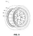
図3Aは、他の例示的実施形態によるホイール140に配設された流れ抵抗バリアを備える、タイヤ騒音吸収システム300を示した斜視図である。図3Bは、図3Aに示した例示的システム300の断面図である。図3Aおよび図3Bに示されるように、システム300は、空気流抵抗バリアを作り出すように、ホイール140に取り付けられた材料の2つの層302、304を備える。層302、304は、図1A、図1B、図2、および図14を参照して上に説明した層110、120の材料と同様の材料を含むことができ、同様にホイール140またはタイヤ160に結合されることができる。したがって、それらの材料は、流れ抵抗バリアおよび摩擦騒音減衰体を作り出す同様の流れ抵抗特性を持つことができる。さらに、層302、304は、図1A、図1B、図2、および図14を参照して上に説明した層110、120と同様の構造を備えることができる。したがって、層302、304は、そこに形成される隙間130を持つ。外側の層302は、外側の層302および内側の層304の開口が重なり合うことがないように、内側の層304に対してずらされる。図示されるとおり、システム300は、図1Aおよび図1Bに図示されたシステム100よりも薄い輪郭を有する。システム100と300との主な違いは、層302、304が、層110、120によって作り出される流れ抵抗バリアよりも薄い輪郭を持つ流れ抵抗バリアを作り出すことにある。層302、304の大きさは、所望の輪郭が作り出されるように調整されることができる。薄い輪郭であることで、ホイール140上の層302、304上に、タイヤ160を組み付けるのを容易にすることができる。
FIG. 3A is a perspective view illustrating a tire
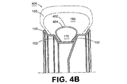
図4Aは、さらに別の例示的実施形態によるホイール140に配設された流れ抵抗バリアを備える、タイヤ騒音吸収システム400を示した斜視図である。図4Bは、図4Aに示された例示的システム400の断面図である。図4Aおよび図4Bに示されるように、システム400は、空気流抵抗バリアを作り出すように、ホイール140に取り付けられた材料の2つの層402、404を備える。層402、404は、図1A、図1B、図2、および図14を参照して上に説明した層110、120の材料と同様の材料を含むことができ、同様にホイール140またはタイヤ160に結合されることができる。したがって、それらの材料は、流れ抵抗バリアおよび摩擦騒音減衰体を作り出す同様の流れ抵抗特性を持つことができる。さらに、層402、404は、図1A、図1B、図2、および図14を参照して上に説明した層110、120と同様の構造を備えることができる。したがって、層402、404は、そこに形成される隙間130を持つ。外側の層402は、外側の層402および内側の層404の隙間130が重なり合うことがないように、内側の層404に対してずらされる。図示されたシステム400の層402、404は、図示されるとおり、上で議論された装置100および300よりも中心寄りの位置で、ホイール140に取り付けられる。すなわち、層402、404は、ホイール140の外側部分に取り付けられない。むしろ、層402、404は、ホイール140の中心断面近くに取り付けられる。図4Aおよび図4Bに示された構成は、ホイール140の空気注入バルブ(図示しない)を覆うことなく、層402、404をホイール140に設置するのを容易にすることができる。
FIG. 4A is a perspective view illustrating a tire
図5は、例示的実施形態による流れ抵抗バリアを作り出す複数の要素502を備える、タイヤ騒音吸収システム500を示した斜視図である。図示されたシステム500は、複数の個別の要素502を備えており、隣り合う要素502の端部が重なり合う。図示するとおり、隣接する要素502の端部は、交互に重なり合うことができる。換言すれば、それぞれの要素502は、隣接する要素502によって重なり合わせられる一方の端と、他の隣接する要素502と重なり合う他方の端とを有することができる。
FIG. 5 is a perspective view of a tire
それぞれの要素502は、図1A、図1B、図2、および図14を参照して上に説明した層110、120の材料と同様の材料を含むことができ、同様にホイール140またはタイヤ160に結合されることができる。したがって、それらの材料は、流れ抵抗バリアおよび摩擦騒音減衰体を作り出す同様の流れ抵抗特性を持つことができる。
Each
例示的実施形態では、要素502は、一度に1つずつホイール140に結合されることができる。あるいは、要素502は、要素502の帯を作り出すためにその外側縁部で互いに結合されることができ、要素502の帯は、ホイールの周囲に巻き付けられかつホイールに結合されることができる。さらに、隣接する要素502によって重なり合わせられる各要素502の一部は、その縁部でホイール140に固定されないままであることができる。この構成は、製造工程により大きな公差を許容することができる。
In the exemplary embodiment,
要素502は、遠心力によって外に押しやられ、重なり合った部分で互いに接することで、流れ抵抗バリアを作り出す。さらに、要素502の重なり合った部分は、音響衝撃波によって偏りを生じると互いにすれ合い、それによって摩擦を生じることで音エネルギーを熱に変換し、音を減衰することができる。したがって、図示されたシステム500は、ホイール140に組み付けられたタイヤ160内において騒音を低減する膜摩擦および流れ抵抗をもたらすことができる。
The
図5に示すように、要素502の重なり合った部分は、それらの重なり合いの中間点で、ファスナ506によって互いに留められる。ファスナ506は、隣接する要素502の間の位置合わせを保つことができるとともに、要素502によって作り出される内部空気キャビティ170の完全性を維持することを助長することができる。例示的実施形態では、ファスナ506は、薄いプラスチックファスナ、糸、膠、ステープル、超音波スポット溶着、または隣接する要素502を互いに適切に所定の位置に保持することができるその他の適切な材料を含むことができる。あるいは、要素502は、留めずにおくことも、または重なり合いに沿った様々な位置で、1つ以上のファスナ506によって留められることもできる。ファスナ506は、本明細書に説明する他の実施形態で、流れ抵抗バリアの位置合わせを保つために使用するのに適している。
As shown in FIG. 5, the overlapping portions of
また、図示されたシステム500の要素502は、ホイール140の空気注入バルブ(図示しない)を覆うように、または覆わないようにして取り付けることが可能であり、タイヤ160をホイール140に信頼性をもって組み付けるための一層の余裕を提供することができる。
Also, the
図6Aは、他の例示的実施形態による、流れ抵抗バリアを作り出す複数の要素602、604を備える、タイヤ騒音吸収システム600を示した斜視図である。図6Bは、図6Aに示された例示的システム600の側面図である。図6Aおよび図6Bに示されるように、システム600は、複数の個別の要素602を備え、各個別の要素602は、2つの隣接する要素604の端部を、量606だけ重なり合う。換言すれば、それぞれの要素602は、隣接する要素604に重なり合う一方の端部と、他の隣接する要素604に重なり合う他方端部とを持つ。それぞれの要素602は、ホイール140に関して外側の要素を表す。それぞれの要素604は、ホイール140に関して内側の要素を表す。
FIG. 6A is a perspective view illustrating a tire
それぞれの要素602、604は、図1A、図1B、図2、および図14を参照して上に説明した層110、120の材料と同様の材料を含むことができ、同様にホイール140またはタイヤ160に結合されることができる。したがって、それらの材料は、流れ抵抗バリアおよび摩擦騒音減衰体を作り出す同様の流れ抵抗特性を持つことができる。
Each
例示的実施形態では、要素602、604は、一度に1つずつ位置150でホイール140に結合されることができる。あるいは、要素602、604は、要素602、604の帯を作り出すように、その外側縁部で互いに結合されることができ、要素602、604の帯は、ホイール140の周囲に巻き付けられることができ、かつホイール140に結合されることができる。さらに、隣接する要素602によって重なり合わせられるそれぞれの要素604の一部は、その縁部でホイール140に固定されないままであることができる。この構成は、製造工程により大きな公差を許容することができる。
In the exemplary embodiment,
図7は、例示的実施形態によるホイール140に結合された不連続な要素702を備える、タイヤ騒音吸収システム700を示した斜視図である。システム700は、接触摩擦を通して騒音を低減する。それぞれの要素702は、重なり合った材料の2つの帯を備えており、それら2つの帯は、衝撃波によって衝撃を与えられたときに互いに対して動く。回転するホイールによってもたらされる遠心力は、2つの帯を互いに接した状態に保ち、両帯間の変位は摩擦を発生させる。摩擦による効果は、音響衝撃波を熱に変え、それによって衝撃波に付随した騒音を低減するというものである。別の例示的実施形態では、それぞれの要素702に追加的な材料の帯を設けることができる。さらに別の例示的実施形態では、要素702をただ1つ備えるだけであることも、ホイール140に結合した任意の数の複数の要素702を備えることもできる。
FIG. 7 is a perspective view illustrating a tire
図8Aは、例示的実施形態による流れ抵抗バリアを作り出す複数の要素802を備える、タイヤ騒音吸収システム800の斜視図である。図8Bは、図8Aに示された例示的システム800の断面図である。図8Aおよび図8Bに示されるように、システム800は、それぞれが構成要素802a、802bを備える複数のインターロッキング要素802を備える。
FIG. 8A is a perspective view of a tire
構成要素802aは、位置150でホイール140に取り付けられる流れ抵抗材料の外側の層(ホイール140に関して)である。構成要素802bは、構成要素802aの下になるその縁部だけで、ホイール140に取り付けられる流れ抵抗材料の内側の層(ホイール140に関して)である。そのため、構成要素802a、802bの表面の間には空間が存在する。
構成要素802bは、構成要素802aよりも長く、Dの距離だけ構成要素802aを超えて突き出る。構成要素802aを超えて延在する構成要素802bの部分は、その縁部が、ホイール140に直接結合する必要がないように、やや細くなっている。図示されたシステム800は、示されるように、複数の連続的な要素802を備え、その1つの要素802の各構成要素802bの突き出た端部が、隣接する要素802の構成要素802aと802bの表面の間にインターロックされる。遠心力が、構成要素802a、802bを外に押しやり、互いに接触させて流れ抵抗バリアを作り出す。さらに、構成要素802a、802bは、互いにすれ合い、それによって摩擦を生じて音エネルギーを熱に変換する。したがって、図示されたシステム800は、ホイール140に組み付けられたタイヤ160内において騒音を低減する、膜摩擦および流れ抵抗をもたらすことができる。
システム800は、タイヤが回転しているときは基本的に密封された流れ抵抗バリアをもたらし、装置がたるんでいるときは、タイヤを膨らませるのに十分な空気の流れをもたらすことができる。例示的実施形態では、それぞれの要素802の構成要素802a、802bは、糸、接着剤、またはその他の適切な材料で結合されることができる。複数の隣接する要素802は、要素802の帯を作るように、それぞれの縁部で互いに結合されることができ、要素802の帯は、ホイール140の周囲に巻かれて結合されることができる。あるいは、要素802は、ホイール140に個別に結合されることができる。
The
要素802は、本明細書で別に説明する様々な方法で、帯または個別のいずれかの形で、ホイール140またはタイヤ160に結合されることができる。例えば、要素802は、ホイールに膠で接着される、溝にはめ込まれる、またはタイヤに膠で接着されるなどが可能である。さらに、隣接する要素802は、図5を参照して上に説明したように、ファスナ506を用いて互いに留められることができる。
Element 802 can be coupled to
要素802は、図1A、図1B、図2、および図14を参照して上に説明した層110、120の材料と同様の材料を含むことができ、同様にホイール140またはタイヤ160に結合されることができる。したがって、それらの材料は、流れ抵抗バリアおよび摩擦騒音減衰体を作り出す流れ抵抗特性を持つことができる。
Element 802 can include a material similar to that of
図9Aは、例示的実施形態による複数の流れ抵抗バリアを作り出す2つ以上の要素902、904を備える、タイヤ騒音吸収システム900を示した斜視図である。図9Bは、図9Aに示された例示的システム900の断面図である。図9Aおよび図9Bに示すように、要素902、904は、本明細書において1つ以上の図1Aから図8Bの図において示されまたは説明されてきた、1つ以上の実施形態を表す。さらに、要素902、904は、以降、1つ以上の図10から図12において説明する1つ以上の実施形態を表すことができる。
FIG. 9A is a perspective view illustrating a tire
例示的実施形態において、要素902、904は、同じ構造を含む。あるいは、要素902、904は、異なる構造を備えることができる。例えば、要素902は、図1Aから図4Bのいずれかに示されるような開口を有する、2つの重なり合う連続した材料の層を備えることができる。要素904は、要素902と同じであることができる。あるいは、要素904は、図5に示された交互に重なり合う要素など、図5から図8Bまたは図10から図12までに示された構造のいずれかを備えることができる。
In the exemplary embodiment,
要素902、904の構造にかかわりなく、それぞれの要素は、図1A、図1B、図2、および図14を参照して上に説明した層110、120の材料と同様の材料を含むことができ、同様にホイール140またはタイヤ160に結合されることができる。したがって、それらの材料は、それぞれの要素902、904について流れ抵抗バリアおよび摩擦騒音減衰体を作り出す流れ抵抗特性を持つことができる。
Regardless of the structure of
2つの要素902、904は、3つの流れ抵抗空気キャビティをタイヤの内部空気室内に形成するように、ホイール140またはタイヤ160に結合される。内部空気キャビティ170は、ホイール140と内側の要素902との間に形成される。中間空気キャビティ975は、要素902と要素904との間に形成される。外部空気キャビティ180は、要素904とタイヤとの間に形成される。別の例示的実施形態では、追加の要素を使用して、タイヤの内部空気室の中により多くの空気流抵抗バリアおよび空気キャビティを作り出すことができる。複数の流れ抵抗バリアを設けることで、それぞれのバリアを通る空気の流れが制限され、それによって通過する音響衝撃波に付随した騒音が吸収される。例示的実施形態では、中間空気キャビティ975は、内部空気キャビティ170の容積よりも小さい容積を持つことができる。別の例示的実施形態では、中間空気キャビティ975は、内部空気キャビティ170の容積よりも約60パーセント〜約75パーセント小さい容積を持つことができる。
The two
例示的実施形態では、要素902、904は、互いに結合され、次にホイール140またはタイヤ160に位置150で結合されることができる。あるいは、それぞれの要素は、同じ位置または別々の位置で個別にホイールまたはタイヤに結合されることができる。結合には、接着剤、クランプ、溝への挿入、またはその他の適切な方法を含め、本明細書で議論されるように、様々な結合手段を用いることができる。
In the exemplary embodiment,
図9Aおよび図9Bに示すように、要素902、904は、3つの空気キャビティ170、180、975を、タイヤの内部空気室内に作り出す。所望であれば、追加的な空気キャビティを作り出すために、追加的な要素を使用することができる。さらに、空気キャビティ170、180、975は、要素902、904をタイヤ160に結合することによって形成されることができる。
As shown in FIGS. 9A and 9B,
図10は、他の例示的実施形態による管状空気流抵抗バリア1002を備える、タイヤ騒音吸収システム1000を示した斜視図である。バリア1002は、バリア1002が、ホイール140およびタイヤ160によって画定されるタイヤの内部空気室内にはめ込まれるように、曲面形状に織られた流れ抵抗材料の管状要素を備える。回転するホイールによってもたらされる遠心力は、管状バリアを起き上がらせて空気で満たし、流れ抵抗空気キャビティを作り出し、流れ抵抗空気キャビティが、バリア1002を通り抜ける衝撃波を吸収することによって、タイヤ騒音が低減される。
FIG. 10 is a perspective view illustrating a tire
管状バリア1002は、様々な適切な方法でホイールの周囲に結合されることができる。例えば、管状バリア1002は、両端を先細りにして結合されることが可能で、そうすることで空気キャビティを1箇所で密封することができる。また、ともに織り上げて、連続した円形の空気キャビティを作り出すこともできる。そうした実施形態は、織り上げられ、またはホイールの周りに直接任意のその他の適切な方法で結合され、あるいは前もって結合され、その後ホイールにはめられることができる。要素1002は、次にホイールまたはタイヤに結合されることができる。あるいは、要素1002は、固定されないまま、ホイール140の外周を取り巻く位置に留まることができる。
要素1002は、図1A、図1B、図2、および図14を参照して上に説明した層110、120の材料と同様の材料を含むことができ、同様にホイール140またはタイヤ160に結合されることができる。したがって、それらの材料は、流れ抵抗バリアを作り出す流れ抵抗特性を持つことができる。
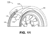
図11は、例示的実施形態による連続的な流れ抵抗バリア1102を備える、タイヤ騒音吸収システム1100を示した斜視図である。バリア1102は、ホイール140の周囲に合うように、曲面形状に織られた三日月形の要素を備える。あるいは、バリア1102の湾曲は、半円またはその他の適切な湾曲であることができる。例えば、バリア1102は、その両端が距離1104だけ隔てられた状態で、円の180度から270度までをなすように湾曲されることができる。バリア1102は、本明細書に説明するあらゆる適切な手段によって、タイヤまたはホイールに結合されることができる。回転するホイール140によってもたらされる遠心力は、バリア1102を起き上がらせて空気で満たし、流れ抵抗バリアを作り出し、流れ抵抗バリアが、要素1002を通り抜ける衝撃波を吸収することによって、タイヤ騒音が低減される。
FIG. 11 is a perspective view of a tire
バリア1102は、図1A、図1B、図2、および図14を参照して上に説明した層110、120の材料と同様の材料を含むことができ(ただし、隙間130は持たない)、同様にホイール140またはタイヤ160に結合されることができる。したがって、それらの材料は、流れ抵抗バリアを作り出す流れ抵抗特性を持つことができる。その一方で、この材料は、タイヤを完全に膨らませるに足るだけの空気の流れをなお提供することができる。
The
図12は、例示的実施形態による複数の管状空気流抵抗バリア1202を備える、タイヤ騒音吸収システム1200を示した斜視図である。バリア1202は、曲面形状に織られ、次にホイール140またはタイヤ160に結合された管状要素であって、図10を参照して上で議論された複数の流れ抵抗空気キャビティにそれぞれ類似する、複数の流れ抵抗空気キャビティを作り出す。あるいは、複数の要素1202は、それぞれの端部1204でともに結合され、ホイール140とタイヤ160によって画定されるタイヤの内部空気室にはめ込まれる円を形成することができる。回転するホイールによってもたらされる遠心力は、バリア1202を起き上がらせて空気で膨らませ、ホイール140の周囲に別個の流れ抵抗キャビティを作り出す。
FIG. 12 is a perspective view illustrating a tire
図13は、例示的実施形態による、図1Aから図12までと図14に示されたいずれの実施形態でも使用することが可能な代表的な要素1300を示した斜視図である。このように、図13は、流れ抵抗バリアを作り出すために上に説明した実施形態のいずれの要素においても利用することができる特徴を持つ要素1300を示している。要素1300は、要素1300に沿って縦方向のパターンをなすように配置された制動体1302を備える。制動体1302は、材料の固有共鳴振動を低減することができ、それによって要素1300が、適正な形状を維持しかつ破損の防止するために、高いトルク条件のもとで剛性を保てるようにする。制動は、吸収能力を高めることができる。なぜなら、吸収体は、存在する音源に共鳴して振動すれば、その性能を減じることになるためである。制動体1302は、シリコーンゴム、浸透性油、糸、エポキシ樹脂、追加の布要素、またはその他適切な材料などの柔軟な材料を含むことができる。柔軟な材料は、要素1300に局所的な補強を加えることで、特定のタイプの布に対して異なる共鳴特性を作り出すことができ、それによって、所望のスペクトルの低周波数エネルギーを標的にすることができる。例えば、制動体1302は、単一の場所に付加することも、あるいは、要素1300に沿って横方向、縦方向、または他の適切な構成のパターンをなすように配置することもできる。
FIG. 13 is a perspective view illustrating an
要素1300は、取付部1304も備える。取付部1304は、要素1300の縁部に取り付けた材料を含み、要素1300をホイール140またはタイヤ160のいずれかに取り付ける際の簡易さと効率を提供する複合的な縁部を構成する。この結合の選択肢は、上に述べた結合の選択肢の可能な代替を提供する。取付部1304は、要素1300の材料をホイール140またはタイヤ160に結合させるよりも容易に、これらに結合される材料を含む。別の例示的実施形態では、取付部1304は、プラスチック、綿、織物、金属、または要素1302をホイール140もしくはタイヤ160に結合するのに適したその他のあらゆる材料を含むことができる。
取付部1304は、接着剤、糸、またはその他の適切な手段で要素1300の材料に取り付けられることができる。図13に示されるように、取付部1304は、要素1300の縁部の長さに沿って要素1300に結合された適切な材料の帯を備える。あるいは、取付部1304は、要素1300の縁部に沿って繰り返し取り付けられた、より小さな異なる片を備えることができる。
The
要素1300は、図1A、図1B、図2、および図14を参照して上に説明した層110、120の材料と同様の材料を含むことができ、同様にホイール140またはタイヤ160に結合されることができる。したがって、それらの材料は、流れ抵抗バリアおよび摩擦騒音減衰体を作り出す流れ抵抗特性を持つことができる。
本明細書で議論されるように、タイヤ騒音低減装置は、開口を持ち、重なり合った材料の連続的な空気流抵抗層、開口を持たない単一の連続した流れ抵抗層、重なり合うおよび/もしくはインターロッキング末端部を有する複数の個別要素、複数の不連続な要素、複数の流れ抵抗バリアを作り出す2つ以上の要素の層、単一の管状要素、半円形の要素、または複数の管状要素を備えることができる。 As discussed herein, a tire noise reduction device may have a continuous air flow resistance layer of overlapping material with openings, a single continuous flow resistance layer without openings, overlapping and / or interfacing. Comprising a plurality of individual elements having a locking end, a plurality of discrete elements, a layer of two or more elements creating a plurality of flow resistance barriers, a single tubular element, a semicircular element, or a plurality of tubular elements be able to.
例示的実施形態では、本明細書に説明する流れ抵抗バリアの材料の少量生産工程は、ホイールおよびタイヤの特定の寸法に層または個々の要素のレーザー切断を含むことができる。大量生産工程は、打抜きであることができる。 In an exemplary embodiment, the low volume production process of flow resistance barrier materials described herein can include laser cutting of layers or individual elements to specific dimensions of wheels and tires. The mass production process can be stamping.
例示的実施形態では、本明細書に説明するタイヤ騒音吸収システムは、約15Hzから約20kHzまでの可聴帯域全域で音を吸収することができる。一部のタイヤ構造は、800Hzを著しく超える周波数の騒音を含まないため、本明細書に説明するタイヤ騒音吸収システムは、約15Hzから約800Hzまでの範囲の音を吸収することもできる。また、流れ抵抗バリアの材料およびバリアによって画定されるキャビティの大きさを変化させることによって、システムの音響周波数吸収特性を所望の範囲に調整することができる。 In an exemplary embodiment, the tire noise absorption system described herein can absorb sound throughout the audible band from about 15 Hz to about 20 kHz. Because some tire structures do not include noise at frequencies significantly above 800 Hz, the tire noise absorbing system described herein can also absorb sound in the range of about 15 Hz to about 800 Hz. Also, by varying the flow resistance barrier material and the size of the cavity defined by the barrier, the acoustic frequency absorption characteristics of the system can be adjusted to a desired range.
本明細書に説明する例示的実施形態によるタイヤ騒音吸収システムは、いくつかの便益を提供することができる。例えば、タイヤ内部のエネルギーの低減は、タイヤ構造のヒステリシスを減らすことができる。この影響は、トレッドの接地バウンスの原因となるエネルギーを低減することで、トレッドの接地性を高めることができる。さらに、ヒステリシスの低減によって、タイヤ温度を下げることができ、それによってタイヤ製造者は、接地性が高い一方で最高温度の低いタイヤコンパウンドを使用することが可能となる。タイヤ温度の低減によって、レーシング条件のもとでのタイヤの寿命を引き延ばすことも可能となる。商業用途では、温度の低減と接地性の増大は、転がり抵抗の低下とタイヤ寿命の増大をもたらすことができる。この影響は、重量トラックや公共輸送などの用途で営業コストの大幅削減につながる。これらの改善点はどれも、タイヤおよび自動車の性能の向上をもたらし得るものである。 The tire noise absorption system according to the exemplary embodiments described herein can provide several benefits. For example, reducing the energy inside the tire can reduce the hysteresis of the tire structure. This influence can improve the grounding property of the tread by reducing the energy that causes the grounding bounce of the tread. In addition, the reduced hysteresis can reduce the tire temperature, which allows the tire manufacturer to use tire compounds that have a high ground but a low maximum temperature. By reducing the tire temperature, it is possible to extend the life of the tire under racing conditions. In commercial applications, reducing temperature and increasing grounding can lead to reduced rolling resistance and increased tire life. This effect will lead to a significant reduction in operating costs for applications such as heavy trucks and public transport. Any of these improvements can result in improved tire and vehicle performance.
装置は、タイヤ内部のエネルギーを吸収し、それによって接地バウンスを低減することで、タイヤの寿命を増大させる。接地バウンスの低減は、路面へのタイヤの接地性を高め、それによってタイヤと路面との間のこすれ合う動きを減らすことができる。接地スリップによってラバーがこすり取られることが、タイヤ摩耗の大きな原因であることから、タイヤ騒音吸収システムは、タイヤの動的性能と接地性を高めることができる。 The device increases the life of the tire by absorbing energy inside the tire, thereby reducing ground bounce. Reduction of the ground bounce can improve the ground contact of the tire to the road surface, thereby reducing the rubbing movement between the tire and the road surface. The fact that the rubber is scraped off due to the contact slip is a major cause of tire wear, and therefore the tire noise absorbing system can improve the dynamic performance and contact performance of the tire.
別の例示的実施形態(図示しない)では、布の層の代わりに、1つ以上の微小孔をあけた金属層を使用することができる。金属層は、ホイール140の外周の周囲に所望の形状を得るように形成されることができ、ホイール140またはホイール140に組み付けたタイヤ160に結合されることができ、ならびにタイヤ160とホイール140との間の内部の空気キャビティ170および外部の空気キャビティ180を作り出すことができる。層内の穿孔は、外部キャビティ180と内部のキャビティ170との間の空気の流れを制限し、それによって、外部のキャビティ180と内部のキャビティ170との間ならびにその逆を伝達される、衝撃波の低周波数エネルギーを吸収することができる。さらに、複数の層が用いられる場合は、衝撃波が、その複数の層を互いに対して動かすようにすることが可能で、それによって、摩擦エネルギーが熱に変換されることで、追加的なエネルギーの吸収が行われる。例示的実施形態によれば、金属層の穿孔は、キャビティ飽和時のキャビティ充填で約10%から約50%までの範囲の空隙率を生じることができる。
In another exemplary embodiment (not shown), a metal layer with one or more micropores can be used in place of the fabric layer. The metal layer can be formed to obtain a desired shape around the outer periphery of the
以上においては具体的な実施形態を詳細に説明してきたが、説明は、あくまでも例証を目的としたものである。上に説明したもののほか、開示された例示的実施形態の態様に対する様々な変形、およびそれらに相当する同等のステップが、特許請求の範囲に規定される本発明の精神および範囲を外れることなく、当業者によって行われ得るものであって、特許請求の範囲に対しては、そうした変更および同等の構造が包含されるべく最も広義の解釈が与えられるべきである。 While specific embodiments have been described in detail above, the description is for illustrative purposes only. In addition to those described above, various modifications to the aspects of the disclosed exemplary embodiments, and equivalent steps thereof, do not depart from the spirit and scope of the invention as defined in the claims. The scope of the claims should be accorded the broadest interpretation so as to encompass such modifications and equivalent structures.
Claims (19)
ホイール上に組み付けられるタイヤであって、ホイールと前記タイヤによって画定される内部空気室を作り出すようなタイヤを備え、
内部空気室内に配設され、内部空気室内にあって流れ抵抗バリアと前記ホイールとの間に空気キャビティを画定するような流れ抵抗バリアを備え、
前記流れ抵抗バリアが、前記流れ抵抗バリアを通過する音響衝撃波に対して音響抵抗をもたらす材料を含み、
前記流れ抵抗バリアが、互いに隣接して配設された複数の層を備え、
前記複数の層それぞれは複数の隙間を有し、
前記複数の層の隣接する層は、互いに隙間の位置がずれるように配設され、
前記流れ抵抗バリアによって画定される空気キャビティは、空気キャビティ内の空気が、衝撃波が前記流れ抵抗バリアを通過して空気キャビティに入ることを許容するような容積を有する、音響衝撃波を消散するシステム。A system for dissipating acoustic shock waves,
A tire assembled on a wheel, the tire creating an internal air chamber defined by the wheel and the tire;
A flow resistance barrier disposed within the internal air chamber and within the internal air chamber to define an air cavity between the flow resistance barrier and the wheel ;
The flow resistance barrier comprises a material that provides acoustic resistance to acoustic shock waves passing through the flow resistance barrier;
The flow resistance barrier comprises a plurality of layers disposed adjacent to each other;
Each of the plurality of layers has a plurality of gaps;
The adjacent layers of the plurality of layers are arranged so that the positions of the gaps are shifted from each other,
A system for dissipating acoustic shock waves, wherein the air cavity defined by the flow resistance barrier has a volume such that air in the air cavity allows the shock wave to pass through the flow resistance barrier and enter the air cavity .
それによって音響衝撃波によって引き起こされる騒音を低減するように音響衝撃波のエネルギーを熱に変換する、請求項1に記載のシステム。Wherein the flow resistance barrier, resulting frictional heat when Ru is displaced by an acoustic shock waves passing therethrough,
Thereby converting the energy of the acoustic shock waves into heat so as to reduce noise caused depending on the acoustic shock wave system according to claim 1.
前記重なり合う要素それぞれが、前記重なり合う要素の隣接する要素の一端と重なり合う、請求項1に記載のシステム。At least one layer of the flow resistance barrier comprises a plurality of overlapping elements disposed continuously around the wheel;
The system of claim 1, wherein each overlapping element overlaps one end of an adjacent element of the overlapping element.
前記複数の要素が、1つおきに前記複数の要素の隣接する要素によってその一方の端部で重なり合い、
前記複数の要素の隣接する別の要素によってそのもう一方の端部で重なり合う、請求項1に記載のシステム。At least one layer of the flow resistance barrier comprises a plurality of elements disposed continuously around the wheel;
The plurality of elements overlap at one end by every other adjacent element of the plurality of elements;
The system of claim 1, wherein the plurality of elements overlap at another end thereof by another adjacent element.
各空気キャビティが、それぞれの空気キャビティ内の空気が、前記流れ抵抗バリアを通過してそれぞれの空気キャビティに入る音響衝撃波の進行に対して比較的小さなインピーダンスを提供するような容積を持つ、請求項1に記載のシステム。The flow resistance barrier defines a plurality of air cavities within an interior air chamber , the flow resistance barrier provides acoustic resistance to an acoustic shock wave that passes through the flow resistance barrier and enters each air cavity;
Each air cavity has a volume such that the air in the respective air cavity provides a relatively small impedance to the progression of acoustic shock waves through the flow resistance barrier and into the respective air cavity. The system according to 1.
ホイールに組み付けられたタイヤによって作り出される内部空気室内に空気キャビティを画定する流れ抵抗バリアを備え、
空気キャビティはタイヤがホイールに組み付けられたとき、前記流れ抵抗バリアと前記ホイールの間に配設されるものであり、
前記流れ抵抗バリアが、前記流れ抵抗バリアを通過する音響衝撃波に対して音響抵抗をもたらす材料を含み、
前記流れ抵抗バリアが、互いに隣接して配設された複数の層を備え、
前記複数の層それぞれは複数の隙間を有し、
前記複数の層の隣接する層は、隣接する層の隙間の位置がずれるように配設され、
前記流れ抵抗バリアによって画定される空気キャビティは、空気キャビティ内の空気が、衝撃波が前記流れ抵抗バリアを通過して空気キャビティに入ることを許容するような容積を持つ、音響衝撃波を消散する装置。A device for dissipating acoustic shock waves,
A flow resistance barrier defining an air cavity in an internal air chamber created by a tire assembled on the wheel;
An air cavity is disposed between the flow resistance barrier and the wheel when the tire is assembled to the wheel,
The flow resistance barrier comprises a material that provides acoustic resistance to acoustic shock waves passing through the flow resistance barrier;
The flow resistance barrier comprises a plurality of layers disposed adjacent to each other;
Each of the plurality of layers has a plurality of gaps;
The adjacent layers of the plurality of layers are arranged so that the position of the gap between the adjacent layers is shifted,
An apparatus for dissipating acoustic shock waves, wherein the air cavity defined by the flow resistance barrier has a volume such that air in the air cavity allows shock waves to pass through the flow resistance barrier and enter the air cavity .
Applications Claiming Priority (2)
| Application Number | Priority Date | Filing Date | Title |
|---|---|---|---|
| US69401805P | 2005-06-24 | 2005-06-24 | |
| PCT/US2006/024598 WO2007002479A2 (en) | 2005-06-24 | 2006-06-23 | Tire and wheel noise reducing device and system |
Related Child Applications (1)
| Application Number | Title | Priority Date | Filing Date |
|---|---|---|---|
| JP2010146213A Division JP2011006063A (en) | 2005-06-24 | 2010-06-28 | Device and system for reducing noise of tire and wheel |
Publications (3)
| Publication Number | Publication Date |
|---|---|
| JP2008543675A JP2008543675A (en) | 2008-12-04 |
| JP2008543675A5 JP2008543675A5 (en) | 2010-08-05 |
| JP4625126B2 true JP4625126B2 (en) | 2011-02-02 |
Family
ID=37595907
Family Applications (2)
| Application Number | Title | Priority Date | Filing Date |
|---|---|---|---|
| JP2008518463A Expired - Fee Related JP4625126B2 (en) | 2005-06-24 | 2006-06-23 | Apparatus and system for reducing tire and wheel noise |
| JP2010146213A Pending JP2011006063A (en) | 2005-06-24 | 2010-06-28 | Device and system for reducing noise of tire and wheel |
Family Applications After (1)
| Application Number | Title | Priority Date | Filing Date |
|---|---|---|---|
| JP2010146213A Pending JP2011006063A (en) | 2005-06-24 | 2010-06-28 | Device and system for reducing noise of tire and wheel |
Country Status (8)
| Country | Link |
|---|---|
| US (3) | US7740035B2 (en) |
| EP (1) | EP1912804B1 (en) |
| JP (2) | JP4625126B2 (en) |
| KR (1) | KR20080038312A (en) |
| CN (1) | CN101291819B (en) |
| BR (1) | BRPI0611591A2 (en) |
| CA (1) | CA2656240A1 (en) |
| WO (1) | WO2007002479A2 (en) |
Families Citing this family (29)
| Publication number | Priority date | Publication date | Assignee | Title |
|---|---|---|---|---|
| CN101291819B (en) * | 2005-06-24 | 2012-06-27 | 轮胎声学有限责任公司 | Tire and wheel noise reducing device and system |
| JP4460593B2 (en) * | 2007-09-19 | 2010-05-12 | 本田技研工業株式会社 | Vehicle wheel |
| WO2009124182A1 (en) * | 2008-04-03 | 2009-10-08 | Tire Acoustics, Llc | Tire and wheel noise reducing device and system |
| US8056594B2 (en) * | 2008-04-11 | 2011-11-15 | Man-Young Jung | Long drive patch for tire puncture |
| US20100071820A1 (en) * | 2008-09-24 | 2010-03-25 | Bridgestone Americas Tire Operations, Llc | Tire and noise reducer |
| EP2174802A1 (en) | 2008-10-08 | 2010-04-14 | Société de Technologie MICHELIN | Tyre having a belt ply with cords disposed along the circumference of the tire to reduce the tire noise |
| DE102009050268A1 (en) | 2009-10-21 | 2011-05-05 | Rema Tip Top Gmbh | Mounting system for attaching brackets to elastomer components |
| JP5565558B2 (en) | 2010-02-01 | 2014-08-06 | 株式会社 アコースティックイノベーションズ | Tire internal equipment support, tire and tire assembly |
| GB2483255A (en) * | 2010-09-01 | 2012-03-07 | Bentley Motors Ltd | Tyre cavity noise absorber |
| GB201017808D0 (en) * | 2010-10-21 | 2010-12-01 | Univ Salford The | An air spring |
| JP6029884B2 (en) | 2012-08-02 | 2016-11-24 | 東洋ゴム工業株式会社 | Pneumatic tire and rim assembly |
| CN107415578B (en) * | 2012-12-17 | 2020-03-31 | 本田技研工业株式会社 | Vehicle wheel |
| EP2962866B1 (en) * | 2013-02-28 | 2019-07-17 | Honda Motor Co., Ltd. | Vehicle wheel |
| WO2014132851A1 (en) * | 2013-02-28 | 2014-09-04 | 本田技研工業株式会社 | Vehicle wheel |
| JP6069097B2 (en) * | 2013-05-21 | 2017-01-25 | 本田技研工業株式会社 | Vehicle wheel |
| US9302537B2 (en) * | 2013-08-16 | 2016-04-05 | GM Global Technology Operations LLC | Noise suppression device for a wheel assembly |
| US9090128B2 (en) * | 2013-08-16 | 2015-07-28 | GM Global Technology Operations LLC | Wheel assembly for a vehicle and a method of manufacturing the wheel assembly |
| GB2519749B (en) * | 2013-10-24 | 2015-08-05 | Bentley Motors Ltd | Tyre cavity noise absorber |
| GB201405647D0 (en) | 2014-03-28 | 2014-05-14 | Carbon Air Ltd | Transfer method and apparatus |
| US10131184B2 (en) * | 2014-08-28 | 2018-11-20 | Ford Global Technologies,Llc | Resonator device and vehicle wheel assembly including the same |
| CN104553633A (en) * | 2014-12-12 | 2015-04-29 | 重庆长安汽车股份有限公司 | Pneumatic tire with noise reduction device |
| CN107428198B (en) * | 2015-03-09 | 2020-09-22 | 本田技研工业株式会社 | Vehicle wheel |
| KR20160116741A (en) * | 2015-03-31 | 2016-10-10 | 현대자동차주식회사 | Wheel resonator for vehicle |
| KR101668187B1 (en) * | 2015-04-04 | 2016-10-20 | 김형철 | A tire with internal vanes |
| KR101625375B1 (en) | 2016-02-19 | 2016-05-30 | 주식회사 지티물류 | Anti-vibration vehicle wheel having an improved rim |
| KR101828315B1 (en) * | 2016-04-29 | 2018-02-12 | 주식회사 팔 | Vehicular Wheel |
| WO2018062586A1 (en) * | 2016-09-29 | 2018-04-05 | 류수형 | Tire provided with inner vanes |
| KR102300663B1 (en) * | 2020-10-28 | 2021-09-09 | 주식회사 대유글로벌 | Two-band fastening type resonator wheel |
| JP2023087586A (en) * | 2021-12-13 | 2023-06-23 | 株式会社ブリヂストン | Sound absorption tool and assembly |
Family Cites Families (65)
| Publication number | Priority date | Publication date | Assignee | Title |
|---|---|---|---|---|
| US466548A (en) * | 1892-01-05 | woodward | ||
| US2502016A (en) * | 1943-11-30 | 1950-03-28 | Rca Corp | Diffraction type sound absorber |
| US2502020A (en) * | 1945-01-26 | 1950-03-28 | Rca Corp | Diffraction type sound absorber with fiber glass walls |
| US2493731A (en) * | 1946-09-10 | 1950-01-03 | Watter Michael | Pneumatic tire |
| FR1096438A (en) | 1953-12-05 | 1955-06-21 | Process for making vehicle tires pressure-proof and puncture-proof | |
| US2901290A (en) * | 1958-04-25 | 1959-08-25 | Chrysler Corp | Wheel mounted vibration damper |
| DE2126289A1 (en) | 1971-05-27 | 1972-12-07 | Achinger, Michael, 8903 Haunstetten | Spiked pneumatic tyre - with spikes slidable in tread wall |
| IT963743B (en) | 1972-08-04 | 1974-01-21 | Pirelli | SAFETY TIRE THAT IS ABLE TO EXPLAIN BOTH AN ANTIFO RO AND AN ANTISPLUSION ACTION |
| DE2442917A1 (en) | 1974-09-07 | 1976-03-18 | Gresch Guenter | Vehicle pneumatic tubeless tyre - has upper tyre section containing air inflatable sponge filling |
| US5109905A (en) * | 1977-12-01 | 1992-05-05 | Lambe Donald M | Dual chamber pneumatic tire with the chambers separated by a collapsible partition wall |
| DE2946273A1 (en) * | 1979-11-16 | 1981-05-21 | Messerschmitt-Bölkow-Blohm GmbH, 8000 München | METHOD FOR REDUCING TIRE NOISE |
| DE3016255A1 (en) * | 1980-04-26 | 1981-10-29 | Messerschmitt-Bölkow-Blohm GmbH, 8000 München | GAS FILLED VEHICLE TIRE |
| DE3317103C2 (en) * | 1983-05-10 | 1986-08-07 | Metzeler Kautschuk GmbH, 8000 München | Resonant, volume-changing resonator in the form of a silator |
| US4755006A (en) * | 1986-09-25 | 1988-07-05 | Clay Sean S C | Dynamic wheel balancing device |
| JPS63130412A (en) * | 1986-11-21 | 1988-06-02 | Honda Motor Co Ltd | Tyre structure for vehicle |
| JPH01115704A (en) | 1987-10-29 | 1989-05-09 | Bridgestone Corp | Low noise tyre wheel |
| JPH04159101A (en) | 1990-10-22 | 1992-06-02 | Mazda Motor Corp | Tire wheel structure of vehicle |
| DE4317268A1 (en) * | 1993-05-24 | 1994-12-01 | Josef Piller | Dividable rim with a mount for tyres having a covering sheath |
| JP3296928B2 (en) * | 1993-12-03 | 2002-07-02 | ユニプレス株式会社 | Sound absorbing wall structure |
| DE4413009A1 (en) * | 1994-04-15 | 1995-10-19 | Naeher Georg Gmbh | Sound absorbers for motor vehicles |
| JPH07315252A (en) * | 1994-05-24 | 1995-12-05 | Isuzu Motors Ltd | Tire noise reducing device |
| US5479974A (en) * | 1994-10-14 | 1996-01-02 | Bridgestone/Firestone, Inc. | Noise-reduction system for vehicle tires |
| JPH1016521A (en) | 1996-06-27 | 1998-01-20 | Honda Motor Co Ltd | Tire with tube, and tubeless tire |
| US5891278A (en) * | 1997-01-07 | 1999-04-06 | Rivin; Evgeny I. | Pneumatic wheels |
| GB2321886B (en) * | 1997-02-07 | 1998-12-30 | John Lawrence Fone | Shock absorbing tyre |
| DE19746649A1 (en) * | 1997-10-22 | 1999-04-29 | Continental Ag | Motor vehicle with a tire mounted on a rim and method for producing a sound absorbing installation |
| DE19819128C2 (en) * | 1998-04-29 | 2000-06-21 | Continental Ag | Motor vehicle wheel with a ring made of sound-absorbing material applied to a rim |
| US6106075A (en) * | 1998-06-02 | 2000-08-22 | Honda Giken Kogyo Kabushiki Kaisha | Road wheel with improved vibration characteristics and method of constructing and utilizing same |
| JP2002539008A (en) * | 1999-03-10 | 2002-11-19 | ハーペー−ケミー ペルツァー | Vehicle wheels, especially passenger vehicle wheels |
| EP1055527B1 (en) * | 1999-05-20 | 2002-09-18 | Ford Global Technologies, Inc. | Wheel rim |
| WO2001023195A1 (en) * | 1999-09-29 | 2001-04-05 | Societe De Technologie Michelin | Safety support with noise suppressor for vehicle wheel |
| JP3695255B2 (en) * | 1999-10-15 | 2005-09-14 | 三菱自動車工業株式会社 | Vehicle wheel structure |
| US6422655B1 (en) * | 1999-11-12 | 2002-07-23 | Continental General Tire, Inc. | Tire inside noise absorber |
| DE60026805T2 (en) * | 1999-12-22 | 2006-10-19 | Sumitomo Rubber Industries Ltd., Kobe | Silencer for tires |
| JP2001239804A (en) * | 1999-12-24 | 2001-09-04 | Sumitomo Rubber Ind Ltd | Assembly of pneumatic tire and rim |
| JP2001187502A (en) * | 1999-12-28 | 2001-07-10 | Sumitomo Rubber Ind Ltd | Rim, tire using it, and rim assembly |
| DE10007375C2 (en) * | 2000-02-18 | 2002-01-17 | August Mohr Gmbh & Co Kg | Rim tube made of textile thread material for attaching at least one sound absorbing body |
| US6533009B2 (en) * | 2000-06-05 | 2003-03-18 | Sumitomo Rubber Industries, Ltd. | Noise damper for pneumatic tire |
| EP1253025B1 (en) * | 2001-04-16 | 2006-02-08 | Sumitomo Rubber Industries Ltd. | Tire noise reducing system |
| US7013940B2 (en) * | 2001-04-19 | 2006-03-21 | Michelin Recherche Et Technique S.A. | Device for attenuating cavity noise in a tire and wheel |
| WO2003001501A1 (en) * | 2001-06-21 | 2003-01-03 | Kabushiki Kaisha Kobe Seiko Sho | Porous soundproof structural body and method of manufacturing the structural body |
| US20030051942A1 (en) * | 2001-09-20 | 2003-03-20 | Atkins Charlie C. | Mobile elevating hut |
| JP3974437B2 (en) | 2002-03-28 | 2007-09-12 | 住友ゴム工業株式会社 | Pneumatic tire |
| JP3988587B2 (en) | 2002-08-28 | 2007-10-10 | 東海ゴム工業株式会社 | Soundproof tire |
| JP2004148978A (en) * | 2002-10-30 | 2004-05-27 | Bridgestone Corp | Support body, and pneumatic run-flat tire |
| JP4353502B2 (en) * | 2003-02-21 | 2009-10-28 | 横浜ゴム株式会社 | Tire / wheel assembly and noise reduction interior |
| JP2004276809A (en) | 2003-03-17 | 2004-10-07 | Honda Motor Co Ltd | Vehicular wheel |
| JP2004306653A (en) * | 2003-04-02 | 2004-11-04 | Honda Motor Co Ltd | Vehicular wheel |
| DE112004001430B4 (en) * | 2003-08-04 | 2017-01-05 | The Yokohama Rubber Co., Ltd. | Low noise pneumatic tire |
| JP2005053383A (en) * | 2003-08-06 | 2005-03-03 | Bridgestone Corp | Safety tire and air bladder for safety tire |
| JP4428062B2 (en) | 2004-01-20 | 2010-03-10 | 横浜ゴム株式会社 | Pneumatic tire |
| JP4044526B2 (en) | 2004-01-27 | 2008-02-06 | 住友ゴム工業株式会社 | Pneumatic tire and rim assembly |
| AU2004200306C9 (en) * | 2004-01-30 | 2010-02-11 | Roger Smith | Bead lock |
| EP1852279B1 (en) | 2004-03-16 | 2009-06-03 | Sumitomo Rubber Industries Ltd. | Pneumatic tire with a plurality of noise dampers |
| JP4415738B2 (en) | 2004-04-14 | 2010-02-17 | 横浜ゴム株式会社 | Tire wheel assembly and run-flat core |
| DE202004008030U1 (en) | 2004-05-19 | 2004-08-12 | Hepp, Rainer, Dr. | Vehicle pneumatic tire has a compressed air chamber, separated into two part-chambers by an impermeable dividing wall, to retain pressure for safe driving in the event of a puncture |
| US7290577B2 (en) * | 2004-05-21 | 2007-11-06 | Garry L. Rumbaugh | Tire with air-flow restrictor |
| JP2006151028A (en) * | 2004-11-25 | 2006-06-15 | Sumitomo Rubber Ind Ltd | Assembly of tire and rim and support ring used therefor |
| JP2006199276A (en) * | 2004-12-24 | 2006-08-03 | Kobe Steel Ltd | Sound absorbing structure |
| JP4175479B2 (en) | 2005-04-28 | 2008-11-05 | 横浜ゴム株式会社 | Noise reduction device, manufacturing method thereof, and pneumatic tire provided with noise reduction device |
| JP2006341681A (en) * | 2005-06-08 | 2006-12-21 | Honda Motor Co Ltd | Tire sound absorbing structure |
| CN101291819B (en) | 2005-06-24 | 2012-06-27 | 轮胎声学有限责任公司 | Tire and wheel noise reducing device and system |
| US7992605B2 (en) | 2007-12-28 | 2011-08-09 | Julian Yee | Multifunctional tire support device |
| WO2009124182A1 (en) | 2008-04-03 | 2009-10-08 | Tire Acoustics, Llc | Tire and wheel noise reducing device and system |
| DE202008009008U1 (en) | 2008-07-03 | 2008-09-04 | Recticel N.V. | vehicle tires |
-
2006
- 2006-06-23 CN CN2006800301587A patent/CN101291819B/en not_active Expired - Fee Related
- 2006-06-23 CA CA002656240A patent/CA2656240A1/en not_active Abandoned
- 2006-06-23 BR BRPI0611591-8A patent/BRPI0611591A2/en not_active IP Right Cessation
- 2006-06-23 EP EP06773891.4A patent/EP1912804B1/en active Active
- 2006-06-23 WO PCT/US2006/024598 patent/WO2007002479A2/en active Application Filing
- 2006-06-23 US US11/473,928 patent/US7740035B2/en not_active Expired - Fee Related
- 2006-06-23 KR KR1020087001870A patent/KR20080038312A/en active IP Right Grant
- 2006-06-23 JP JP2008518463A patent/JP4625126B2/en not_active Expired - Fee Related
-
2010
- 2010-05-13 US US12/779,576 patent/US8196628B2/en not_active Expired - Fee Related
- 2010-06-28 JP JP2010146213A patent/JP2011006063A/en active Pending
-
2012
- 2012-06-11 US US13/493,726 patent/US20120247636A1/en not_active Abandoned
Also Published As
| Publication number | Publication date |
|---|---|
| US20100218870A1 (en) | 2010-09-02 |
| US20060289100A1 (en) | 2006-12-28 |
| US8196628B2 (en) | 2012-06-12 |
| BRPI0611591A2 (en) | 2010-09-21 |
| US20120247636A1 (en) | 2012-10-04 |
| CN101291819B (en) | 2012-06-27 |
| CA2656240A1 (en) | 2007-01-04 |
| WO2007002479A2 (en) | 2007-01-04 |
| CN101291819A (en) | 2008-10-22 |
| WO2007002479A3 (en) | 2007-04-26 |
| JP2011006063A (en) | 2011-01-13 |
| EP1912804B1 (en) | 2013-09-25 |
| KR20080038312A (en) | 2008-05-06 |
| EP1912804A2 (en) | 2008-04-23 |
| EP1912804A4 (en) | 2008-12-03 |
| US7740035B2 (en) | 2010-06-22 |
| JP2008543675A (en) | 2008-12-04 |
Similar Documents
| Publication | Publication Date | Title |
|---|---|---|
| JP4625126B2 (en) | Apparatus and system for reducing tire and wheel noise | |
| JP5357242B2 (en) | Apparatus and system for reducing tire and wheel noise | |
| JP6029884B2 (en) | Pneumatic tire and rim assembly | |
| US6953205B2 (en) | Multilayer molded element | |
| CA2161741C (en) | Noise-reduction system for vehicle tires | |
| JP2018158714A (en) | Resonance sound reducing pneumatic tire | |
| KR20080066851A (en) | In tyre sound absorber | |
| JP6434971B2 (en) | Tire cavity resonance sound absorber | |
| WO2005058616A1 (en) | Low noise pneumatic tire | |
| KR20010043095A (en) | Method for fixing a ring made of a sound-absorbing material on a rim and motor vehicle wheel having a ring made of sound-absorbing material fixed on the rim | |
| JP2009255908A (en) | Vehicle body construction, strut for vehicle, and inner panel | |
| JP7089418B2 (en) | Pneumatic tires | |
| JP5286856B2 (en) | Car body structure, vehicle roof and roof inner panel | |
| MX2008000313A (en) | Tire and wheel noise reducing device and system | |
| JP5833912B2 (en) | Tire having vibration noise absorbing structure and manufacturing method thereof | |
| EP3778267B1 (en) | Pneumatic tyre and method for the construction of said pneumatic tyre | |
| KR102393468B1 (en) | Vehicle wheels including a housing having a sound absorbing module having a porous structure | |
| CN113242800B (en) | Pneumatic tire | |
| CN108116156B (en) | Noise reduction block for high-speed railway wheels | |
| JP2009208690A (en) | Vehicle body structure, plate for partition, and rear package tray | |
| EP2907678B1 (en) | Noise absorber inside the tire cavity |
Legal Events
| Date | Code | Title | Description |
|---|---|---|---|
| A529 | Written submission of copy of amendment under section 34 (pct) |
Free format text: JAPANESE INTERMEDIATE CODE: A529 Effective date: 20080220 |
|
| A621 | Written request for application examination |
Free format text: JAPANESE INTERMEDIATE CODE: A621 Effective date: 20090602 |
|
| A521 | Written amendment |
Free format text: JAPANESE INTERMEDIATE CODE: A523 Effective date: 20100524 |
|
| RD02 | Notification of acceptance of power of attorney |
Free format text: JAPANESE INTERMEDIATE CODE: A7422 Effective date: 20100528 |
|
| A521 | Written amendment |
Free format text: JAPANESE INTERMEDIATE CODE: A523 Effective date: 20100614 |
|
| A871 | Explanation of circumstances concerning accelerated examination |
Free format text: JAPANESE INTERMEDIATE CODE: A871 Effective date: 20100614 |
|
| RD04 | Notification of resignation of power of attorney |
Free format text: JAPANESE INTERMEDIATE CODE: A7424 Effective date: 20100602 |
|
| A521 | Written amendment |
Free format text: JAPANESE INTERMEDIATE CODE: A523 Effective date: 20100524 |
|
| A975 | Report on accelerated examination |
Free format text: JAPANESE INTERMEDIATE CODE: A971005 Effective date: 20100715 |
|
| A131 | Notification of reasons for refusal |
Free format text: JAPANESE INTERMEDIATE CODE: A131 Effective date: 20100720 |
|
| A521 | Written amendment |
Free format text: JAPANESE INTERMEDIATE CODE: A523 Effective date: 20100802 |
|
| A521 | Written amendment |
Free format text: JAPANESE INTERMEDIATE CODE: A821 Effective date: 20100803 |
|
| TRDD | Decision of grant or rejection written | ||
| A01 | Written decision to grant a patent or to grant a registration (utility model) |
Free format text: JAPANESE INTERMEDIATE CODE: A01 Effective date: 20101029 |
|
| A01 | Written decision to grant a patent or to grant a registration (utility model) |
Free format text: JAPANESE INTERMEDIATE CODE: A01 |
|
| A61 | First payment of annual fees (during grant procedure) |
Free format text: JAPANESE INTERMEDIATE CODE: A61 Effective date: 20101104 |
|
| R150 | Certificate of patent or registration of utility model |
Free format text: JAPANESE INTERMEDIATE CODE: R150 |
|
| FPAY | Renewal fee payment (event date is renewal date of database) |
Free format text: PAYMENT UNTIL: 20131112 Year of fee payment: 3 |
|
| RD02 | Notification of acceptance of power of attorney |
Free format text: JAPANESE INTERMEDIATE CODE: R3D02 |
|
| FPAY | Renewal fee payment (event date is renewal date of database) |
Free format text: PAYMENT UNTIL: 20131112 Year of fee payment: 3 |
|
| RD04 | Notification of resignation of power of attorney |
Free format text: JAPANESE INTERMEDIATE CODE: R3D04 |
|
| LAPS | Cancellation because of no payment of annual fees |