KR20080038312A - Tire and wheel noise reducing device and system - Google Patents
Tire and wheel noise reducing device and system Download PDFInfo
- Publication number
- KR20080038312A KR20080038312A KR1020087001870A KR20087001870A KR20080038312A KR 20080038312 A KR20080038312 A KR 20080038312A KR 1020087001870 A KR1020087001870 A KR 1020087001870A KR 20087001870 A KR20087001870 A KR 20087001870A KR 20080038312 A KR20080038312 A KR 20080038312A
- Authority
- KR
- South Korea
- Prior art keywords
- barrier
- wheel
- tire
- layers
- elements
- Prior art date
Links
Images


Classifications
-
- B—PERFORMING OPERATIONS; TRANSPORTING
- B60—VEHICLES IN GENERAL
- B60C—VEHICLE TYRES; TYRE INFLATION; TYRE CHANGING; CONNECTING VALVES TO INFLATABLE ELASTIC BODIES IN GENERAL; DEVICES OR ARRANGEMENTS RELATED TO TYRES
- B60C5/00—Inflatable pneumatic tyres or inner tubes
- B60C5/20—Inflatable pneumatic tyres or inner tubes having multiple separate inflatable chambers
-
- B—PERFORMING OPERATIONS; TRANSPORTING
- B60—VEHICLES IN GENERAL
- B60C—VEHICLE TYRES; TYRE INFLATION; TYRE CHANGING; CONNECTING VALVES TO INFLATABLE ELASTIC BODIES IN GENERAL; DEVICES OR ARRANGEMENTS RELATED TO TYRES
- B60C19/00—Tyre parts or constructions not otherwise provided for
- B60C19/002—Noise damping elements provided in the tyre structure or attached thereto, e.g. in the tyre interior
-
- B—PERFORMING OPERATIONS; TRANSPORTING
- B60—VEHICLES IN GENERAL
- B60C—VEHICLE TYRES; TYRE INFLATION; TYRE CHANGING; CONNECTING VALVES TO INFLATABLE ELASTIC BODIES IN GENERAL; DEVICES OR ARRANGEMENTS RELATED TO TYRES
- B60C5/00—Inflatable pneumatic tyres or inner tubes
-
- Y—GENERAL TAGGING OF NEW TECHNOLOGICAL DEVELOPMENTS; GENERAL TAGGING OF CROSS-SECTIONAL TECHNOLOGIES SPANNING OVER SEVERAL SECTIONS OF THE IPC; TECHNICAL SUBJECTS COVERED BY FORMER USPC CROSS-REFERENCE ART COLLECTIONS [XRACs] AND DIGESTS
- Y10—TECHNICAL SUBJECTS COVERED BY FORMER USPC
- Y10T—TECHNICAL SUBJECTS COVERED BY FORMER US CLASSIFICATION
- Y10T152/00—Resilient tires and wheels
- Y10T152/10—Tires, resilient
- Y10T152/10495—Pneumatic tire or inner tube
- Y10T152/10522—Multiple chamber
- Y10T152/10531—Cylinder and piston
- Y10T152/1054—Mutually free walls
Abstract
Description
본 발명은 일반적으로 타이어들 및 휠들로부터 차량 노이즈를 감소시키는 것에 관한 것이다. 상세하게는 본 발명은 타이어 및 타이어가 장착되는 휠에 의해 생성되는 내부 공기 챔버 내에 위치된 사운드 감소 장치에 관한 것이다.The present invention relates generally to reducing vehicle noise from tires and wheels. Specifically, the present invention relates to a sound reduction device located in an interior air chamber created by a tire and a wheel on which the tire is mounted.
자동차 타이어들이 도로 표면과 접촉할 때, 이들은 상당한 노이즈를 만들어 낸다. 어떠한 차량들에서는 25mph 이상의 속도에서 타이어 노이즈가 결합된 모든 다른 차량 노이즈 소스들보다 클 수 있다. 따라서, 자동차 및 타이어 제조업자들은 타이어 노이즈를 감소시키기 위한 연구 개발에 해마다 많은 양의 자원을 소비한다.When car tires come in contact with the road surface, they produce significant noise. In some vehicles, tire noise may be greater than all other vehicle noise sources combined at speeds above 25 mph. Therefore, automobile and tire manufacturers spend a large amount of resources each year on research and development to reduce tire noise.
타이어 노이즈는 많은 소스들로부터 기인한다. 예를 들어, 타이어 노이즈는 (1) 타이어와 도로 표면의 접촉에 의해 유발되는 타이어 변형으로부터의 내부 타이어 공기 챔버의 여진(excitation)에 의해 생성되는 저주파 쇼크 웨이브들; (2) 도로 접촉시 타이어의 변형에 의해 유발되는 공기 챔버 여진에 기인한 저주파 타이어 구조 링잉(ringing); (3) 트레드(tread)와 도로 표면 사이에 임시로 잡혀진 공기에 의해 유발되는 고주파 외부 트레드 공기 압축; 및 (4) 타이어와 도로 표면 사이의 마찰에 의해 유발되는 고주파 접촉 스크럽(scrub)으로부터 유발된다.Tire noise comes from many sources. For example, tire noise may include (1) low frequency shock waves generated by excitation of the internal tire air chamber from tire deformation caused by contact of the tire with the road surface; (2) low frequency tire structure ringing due to air chamber excitation caused by deformation of the tire upon road contact; (3) high frequency external tread air compression caused by air temporarily trapped between the tread and the road surface; And (4) from high frequency contact scrub caused by friction between the tire and the road surface.
몇몇 트레드 공기 압축 노이즈는 피할 수 없다. 예를 들어, 트레드 공기 압축은 도로 접촉시에 물과 공기를 압축하고, 트레드 해제시(tread release) 상기 혼합을 팽창시킴에 의해 트레드 접촉 표면으로부터 물을 제거하도록 행동한다. 또한, 타이어들이 도로 표면과 함께 마찰 및 노이즈를 생성하는 유한한 어드히젼(adhesion)을 가지기 때문에, 몇몇 접촉 스크럽 노이즈는 피할 수 없다.Some tread air compression noise is inevitable. For example, tread air compression acts to remove water from the tread contact surface by compressing water and air upon road contact and expanding the mixture on tread release. In addition, some contact scrub noises are unavoidable because the tires have finite advice that creates friction and noise with the road surface.
타이어 변형으로부터의 쇼크 웨이브 에너지는 트레드 접촉 영역으로부터 타이어 및 타이어가 장착되는 휠에 의해 생성되는 내부 타이어 공기 챔버로 전달된다. 내부 타이어 공기 챔버 안으로 전달되는 에너지는 휠에 대한 노이즈의 커플링(coupling) 및 타이어 링잉(ringing)에 의해 단지 소산된다. 이러한 타이어 링잉 및 노이즈 커플링은 전체 타이어 노이즈 양의 많은 부분을 차지한다.Shock wave energy from the tire deformation is transferred from the tread contact area to the inner tire air chamber created by the tire and the wheel on which the tire is mounted. The energy delivered into the inner tire air chamber is only dissipated by the coupling of noise and tire ringing to the wheels. Such tire ringing and noise coupling account for a large portion of the total tire noise amount.
타이어 노이즈를 감소시키기 위한 종래의 방법들은 몇몇 결함을 가진다. 상세하게는, 이들 방법들은 타이어 노이즈를 생성하는 쇼크 웨이브들과 관련된 저주파 에너지 (예를 들어, 800Hz 이하)를 효과적으로 흡수하지 않는다. 타이어들이 상당한 저주파 에너지를 생성하기 때문에, 효과적인 타이어 노이즈 흡수기가 이러한 저주파 에너지에 의해 생성되는 노이즈를 감소시켜야만 한다. 그러나, 종래의 방법들은 이러한 노이즈들을 충분하게 감소시키지 않는다. 이 외에도, 저주파 노이즈는 트레드 공기 압축 및 타이어 스크럽에 의해 생성된, 감지된 고주파 노이즈를 증가시킨다. 따라서, 종래의 방법들은 저주파 에너지 노이즈를 감소시키는 것을 실패함에 의해 감지된 고주파 타이어 노이즈를 감소시킬 수 없다. 다른 결함들은 종래의 방법을 사용할 때 휠에 대한 타이어 장착의 어려움, 차량 동작 중에 종래의 방법이 실패하는 경우의 가능한 손실, 및 종래 방법들의 비효율성을 포함한다.Conventional methods for reducing tire noise have some drawbacks. In particular, these methods do not effectively absorb the low frequency energy (eg, below 800 Hz) associated with shock waves that produce tire noise. Since tires produce significant low frequency energy, an effective tire noise absorber must reduce the noise generated by this low frequency energy. However, conventional methods do not reduce these noises sufficiently. In addition, low frequency noise increases the perceived high frequency noise generated by tread air compression and tire scrub. Thus, conventional methods cannot reduce the sensed high frequency tire noise by failing to reduce low frequency energy noise. Other deficiencies include the difficulty of mounting the tires on the wheels when using the conventional methods, possible losses when the conventional methods fail during vehicle operation, and inefficiencies of the conventional methods.
종래의 저주파 노이즈 흡수 방법은 존재한다. 그러나, 이러한 종래의 방법들은 타이어의 공기 챔버와 같은 작은 내부 공기 챔버들에 대해서는 실용적이지 않다. 이러한 종래의 저주파 흡수 방법들은 타이어 공기 챔버에 대하여 너무 크고, 타이어 팽창을 막으며, 효율적이지 않고, 그리고/또는 만일 타이어와 결합되어 사용된다면, 안전상 위험을 지닌다. Conventional low frequency noise absorption methods exist. However, these conventional methods are not practical for small internal air chambers, such as the tire's air chamber. These conventional low frequency absorption methods are too large for the tire air chamber, prevent tire inflation, inefficient, and / or present a safety risk if used in combination with the tire.
따라서, 타이어 및 타이어가 장착되는 휠에 의해 발생되거나 이들 내부에서 발생되는 노이즈를 감소시키기 위한 요구가 당업계에 존재한다. 특히, 타이어의 내부 공기 챔버 내에서 에너지를 흡수하거나 감소시킴에 의해 타이어 노이즈를 감소시키기 위한 요구가 당업계에 존재한다. 더욱 상세하게는, 작동시 타이어의 에어 챔버와 같은 작은 내부 공기 챔버 내부에서 저주파 에너지를 흡수하거나 감소시킬 수 있는 타이어 노이즈 흡수기/감소기에 대한 요구가 존재한다. Accordingly, there is a need in the art to reduce noise generated by or within a tire and a wheel on which the tire is mounted. In particular, there is a need in the art to reduce tire noise by absorbing or reducing energy in the internal air chamber of a tire. More specifically, there is a need for a tire noise absorber / reducer that can absorb or reduce low frequency energy inside a small internal air chamber such as the tire's air chamber during operation.
타이어 노이즈를 감소시키기 위한 장치는 타이어 노이즈를 생성하는 저주파 에너지를 흡수 및 감소시킬 수 있다. 본 장치는 공기 유동 저항 배리어를 가지는 용기를 교대로 가압 및 감압함에 의해 사운드 쇼크 웨이브들을 흡수할 수 있다. 유동 저항 배리어는 용기 내부로의 압력 유동 및 용기로부터의 압력 유동을 댐핑하여 배리어를 통하려 지나가는 쇼크 웨이브들을 댐핑한다. 또한, 용기의 유동 저항 요소 내의 마찰은 사운드 에너지를 열로 변환하고, 이에 따라 사운드를 약하게 한다. 또한, 하이브리드 장치는 공기 유동 저항 캐비티 흡수기의 요소들 및 마찰 흡수기의 요소들을 가질 수 있다.An apparatus for reducing tire noise can absorb and reduce low frequency energy that produces tire noise. The apparatus can absorb sound shock waves by alternately pressurizing and depressurizing a vessel having an airflow resistance barrier. The flow resistance barrier dampens the pressure flow into the vessel and the pressure flow from the vessel to damp shock waves passing through the barrier. In addition, friction in the flow resistance element of the vessel converts the sound energy into heat, thereby weakening the sound. In addition, the hybrid device may have elements of an air flow resistance cavity absorber and elements of a friction absorber.
일 양상에 따라, 타이어 노이즈 흡수 장치는 각 레이어에 복수 개의 개구들을 가지는 공기 유동 저항 물질의 복수 개의 레이어들을 포함할 수 있다. 레이어들은 각 레이어의 개구들이 인접한 레이어의 겹쳐진 부분들에 대하여 오프셋(offset)되도록 결합될 수 있다. 오프셋 개구들은 타이어가 정지되고 레이어들이 느슨할 때 공기가 레이어들을 통과하여 지나가도록 하고, 이에 따라 타이어의 완전한 팽창(inflation)을 허용한다. 겹쳐진 레이어들은 휠에 연결되거나 타이어에 직접 연결될 수 있어서 겹쳐진 요소들의 루프(loop)들을 형성한다. 자동차가 움직이고 타이어가 회전하기 시작할 때, 원심력은 겹쳐진 레이어들에 함께 바깥 방향으로 힘을 가하여 개구들의 공기 통로들을 밀봉하고 휠과 직물 레이어(cloth layer)들 사이에 공기 유동 저항 캐비티를 형성한다. 특히, 안쪽 레이어는 바깥쪽 레이어에 대하여 바깥쪽으로 힘이 가해지고, 안쪽 레이어의 개구들은 바깥쪽 레이어에 의해 밀봉되고, 바깥쪽 레이어의 개구들은 안쪽 레이어에 의해 밀봉된다. 레이어들은 레이어들의 타이어쪽(바깥쪽)과 레이어들의 휠쪽(안쪽) 사이에서 공기 흐름을 제한하고, 이에 따라 공기가 레이어들을 통하여 지나갈 때 저주파 에너지 노이즈를 흡수한다.According to one aspect, the tire noise absorbing device may comprise a plurality of layers of air flow resistant material having a plurality of openings in each layer. The layers may be combined such that the openings in each layer are offset with respect to overlapping portions of adjacent layers. Offset openings allow air to pass through the layers when the tire is stationary and the layers are loose, thus allowing for complete inflation of the tire. The overlapping layers can be connected to the wheel or directly to the tire, forming loops of overlapping elements. As the car moves and the tire starts to rotate, the centrifugal force exerts an outward force on the overlapping layers to seal the air passages of the openings and form an air flow resistance cavity between the wheel and the cloth layers. In particular, the inner layer is forced outward relative to the outer layer, the openings of the inner layer are sealed by the outer layer, and the openings of the outer layer are sealed by the inner layer. The layers restrict air flow between the tire side (outside) of the layers and the wheel side (inside) of the layers, thus absorbing low frequency energy noise as the air passes through the layers.
다른 실시예에서, 레이어들은, 저주파 쇼크 웨이브들에 의해 움직여 질 때, 상호 간에 대하여 미끄러져 마찰을 생성할 수 있다. 생성된 마찰은, 마찰에 의해 생성된 열을 통해 이러한 쇼크 웨이브들을 소산시킴에 의해 추가적인 저주파 에너지 노이즈를 흡수할 수 있다.In another embodiment, the layers can slide against each other to create friction when moved by low frequency shock waves. The generated friction can absorb additional low frequency energy noise by dissipating these shock waves through the heat generated by the friction.
저주파 에너지의 흡수를 증가시키는 것이 트레드 설계 또는 타이어 어드히젼을 양보하지 않고도 감지된 고주파 타이어 노이즈를 감소시킬 수도 있다. 설계는 제조 공정 동안 또는 그 후에, 기존의 타이어에 쉽게 맞출 수 있고, 기존의 휠 또는 타이어에 장착될 수 있다.Increasing the absorption of low frequency energy may reduce the sensed high frequency tire noise without compromising the tread design or tire advice. The design can be easily adapted to existing tires and mounted on existing wheels or tires during or after the manufacturing process.
다른 양상들은 본 장치를 휠 또는 타이어에 부착하는 위치 및 연결 방법의 변경을 포함한다. 예를 들어, 본 장치는 휠의 중앙 위치에서 또는 상이한 형상의 유동 저항 캐비티들을 제공하는 다양한 프로파일(profile)을 가지고 연결될 수 있다. 또한, 다른 양상들은 유동 저항 캐비티를 생성하기 위하여 겹치는(overlapping) 종단들 또는 맞물린(interlocking) 종단들을 가진 복수 개의 요소들을 포함한다. 이들 요소들은 원심력에 의해 바깥쪽으로 힘을 받고, 겹쳐지거나 맞물린 부분들이 함께 움직일 때 캐비티를 형성하여 공기 유동에 저항하는 장치를 생성한다. 또한, 겹쳐진 부분들은, 쇼크 웨이브들에 의하여 움직여 질 때, 마찰을 생성하여 저주파 노이즈를 더 흡수할 수 있다. 그러나 다른 양상은 휠 또는 타이어 주변에 2 개 이상의 유동 저항 요소들을 배열함에 의해 복수 개의 유동 저항 공기 캐비티를 생성하는 것을 포함한다. 이들 복수 개의 유동 저항 공기 캐비티들은 쇼크 웨이브들을 흡수할 수 있고, 노이즈 감소를 향상시킬 수 있다. 다른 양상들은 휠 또는 타이어 상에 위치된 관 형태, 초승달 형태, 또는 굽은 형태의 요소를 포함하고, 이에 따라 단일의 유동 저항 캐비티를 생성한다. 또한 관 형태를 가진 이러한 요소는 휠 주변에 복수 개의 유동 저항 캐비티들을 생성하기 위하여 해체하여 사용될 수도 있다.Other aspects include changing the location and connection method of attaching the device to a wheel or tire. For example, the device can be connected at a central position of the wheel or with various profiles providing different shaped flow resistance cavities. Other aspects also include a plurality of elements having overlapping or interlocking ends to create a flow resistance cavity. These elements are forced outward by centrifugal forces and form a cavity when overlapping or interlocking portions move together to create a device that resists air flow. In addition, the overlapped portions, when moved by the shock waves, may generate friction to further absorb low frequency noise. However, another aspect includes creating a plurality of flow resistance air cavities by arranging two or more flow resistance elements around the wheel or tire. These plurality of flow resistance air cavities can absorb shock waves and improve noise reduction. Other aspects include tubular, crescent, or curved elements located on a wheel or tire, thereby creating a single flow resistance cavity. This element in tubular form may also be used by dismantling to create a plurality of flow resistance cavities around the wheel.
기재된 장치들은 다양한 방법으로 휠 또는 타이어에 연결될 수 있다. 예를 들어 유동 저항 캐비티를 생성하는 요소들은, 휠 또는 타이어 내에서 그루브 또는 플랜지로 크림핑(crimping)됨에 의해, 또는 휠 또는 타이어로 웰딩되거나(welded) 몰딩되거나(molded) 위빙됨(weaved)에 의해, 접착제 또는 클램프를 가지고 휠 또는 타이어에 연결될 수 있다.The described devices can be connected to the wheel or tire in various ways. For example, the elements that create the flow resistance cavity may be crimped with grooves or flanges in the wheels or tires, or welded or molded or weaved into the wheels or tires. By means of adhesives or clamps.
도 1a는 예시적인 실시예에 따른, 타이어에 대하여 휠에 위치된 유동 저항 배리어를 포함하는 타이어 노이즈 흡수 시스템을 도시하는 사시도이다.1A is a perspective view illustrating a tire noise absorbing system that includes a flow resistance barrier positioned at a wheel relative to a tire, according to an exemplary embodiment.
도 1b는 도 1a에 도시된 예시적인 시스템의 단면도이다.FIG. 1B is a cross-sectional view of the example system shown in FIG. 1A.
도 2는 예시적인 실시예에 따른, 도 1a 및 도 1b에 도시된 타이어 노이즈 흡수 시스템의 레이어들의 특징들을 도시한다.2 illustrates the features of the layers of the tire noise absorption system shown in FIGS. 1A and 1B, according to an exemplary embodiment.
도 3a는 다른 예시적인 실시예에 따른, 타이어에 대하여 휠에 위치된 유동 저항 배리어를 포함하는 타이어 노이즈 흡수 시스템을 도시하는 사시도이다.3A is a perspective view illustrating a tire noise absorbing system that includes a flow resistance barrier positioned at a wheel relative to a tire, according to another exemplary embodiment.
도 3b는 도 3a에 도시된 예시적인 시스템의 단면도이다.3B is a cross-sectional view of the example system shown in FIG. 3A.
도 4a는 또 다른 예시적인 실시예에 따른 타이어에 대하여 휠에 위치한 유동 저항 배리어를 포함하는 타이어 노이즈 흡수 시스템을 도시하는 사시도이다.4A is a perspective view illustrating a tire noise absorption system including a flow resistance barrier positioned at a wheel for a tire according to another exemplary embodiment.
도 4b는 도 4a에 도시된 예시적인 시스템의 단면도이다.4B is a cross-sectional view of the example system shown in FIG. 4A.
도 5는 예시적인 실시예에 따른, 유동 저항 배리어를 생성하는 복수 개의 요소들을 포함하는 타이어 노이즈 흡수 시스템을 도시하는 사시도이다.5 is a perspective view illustrating a tire noise absorption system including a plurality of elements for creating a flow resistance barrier, according to an exemplary embodiment.
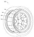
도 6a는 다른 예시적인 실시예에 따른, 유동 저항 배리어를 생성하는 복수 개의 요소들을 포함하는 타이어 노이즈 흡수 시스템의 일부를 도시하는 사시도이 다.6A is a perspective view illustrating a portion of a tire noise absorbing system including a plurality of elements for creating a flow resistance barrier, according to another exemplary embodiment.
도 6b는 도 6a에 도시된 예시적인 시스템의 측면도이다.6B is a side view of the example system shown in FIG. 6A.
도 7은 예시적인 실시예에 따른, 휠에 연결된 불연속적인 요소들을 포함하는 타이어 노이즈 흡수 시스템을 도시하는 사시도이다.FIG. 7 is a perspective view illustrating a tire noise absorbing system including discrete elements connected to a wheel, according to an exemplary embodiment. FIG.
도 8a는 예시적인 실시예에 따른, 유동 저항 배리어를 생성하는 복수 개의 요소들을 포함하는 타이어 노이즈 흡수 시스템의 사시도이다.8A is a perspective view of a tire noise absorbing system including a plurality of elements for creating a flow resistance barrier, according to an exemplary embodiment.
도 8b는 도 8a에 도시된 예시적인 시스템의 단면도이다.8B is a cross-sectional view of the example system shown in FIG. 8A.
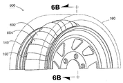
도 9a는 예시적인 실시예에 따른, 복수 개의 유동 저항 배리어들을 생성하는 2 개 이상의 요소들을 포함하는 타이어 노이즈 흡수 시스템을 도시하는 사시도이다.9A is a perspective view illustrating a tire noise absorbing system including two or more elements that produce a plurality of flow resistance barriers, in accordance with an exemplary embodiment.
도 9b는 도 9a에 도시된 예시적인 시스템의 단면도이다.9B is a cross-sectional view of the example system shown in FIG. 9A.
도 10은 다른 예시적인 실시예에 따른, 관 형태의 공기 유동 저항 배리어를 포함하는 타이어 노이즈 흡수 시스템을 도시하는 사시도이다.FIG. 10 is a perspective view illustrating a tire noise absorbing system including a tubular air flow resistance barrier, according to another exemplary embodiment. FIG.
도 11은 예시적인 실시예에 따른, 연속적인 유동 저항 배리어를 포함하는 타이어 노이즈 흡수 시스템을 도시하는 사시도이다.11 is a perspective view illustrating a tire noise absorbing system including a continuous flow resistance barrier, according to an exemplary embodiment.
도 12는 예시적인 실시예에 따른, 복수 개의 관 형태의 공기 유동 저항 배리어들을 포함하는 타이어 노이즈 흡수 시스템을 도시하는 사시도이다.12 is a perspective view illustrating a tire noise absorbing system including a plurality of tubular air flow resistance barriers, according to an exemplary embodiment.
도 13은 예시적인 실시예에 따른, 도 1-12 및 14에 도시된 어떠한 실시예에서도 사용될 수 있는 대표적인 요소를 도시하는 사시도이다.13 is a perspective view illustrating representative elements that may be used in any of the embodiments shown in FIGS. 1-12 and 14, according to an exemplary embodiment.
도 14는 예시적인 실시예에 따른, 휠에 장착된 타이어와 연결된 유동 저항 배리어를 포함하는 타이어 노이즈 흡수 시스템의 단면도이다.14 is a cross-sectional view of a tire noise absorbing system including a flow resistance barrier coupled with a tire mounted to a wheel, according to an exemplary embodiment.
예시적인 실시예들이 도 1-13을 참조하여 설명될 것이며, 동일한 참조부호는 유사한 요소들을 나타낸다.Exemplary embodiments will be described with reference to FIGS. 1-13, wherein like reference numerals denote similar elements.
도 1a는 예시적인 실시예에 따른 타이어(160)에 대하여 휠(140)에 위치된 유동 저항 배리어를 포함하는 타이어 노이즈 흡수 시스템(100)을 도시하는 사시도이다. 도 1b는 도 1a에 도시된 예시적인 시스템(100)의 단면도이다. 도 1a 및 1b에 도시된 바와 같이, 시스템(100)은 복수 개의 겹쳐진, 물질의 레이어들(110, 120)을 포함하고, 이것은 음향적인 유동 저항 배리어를 형성한다. 레이어(110)는 휠(140)에 관련된 바깥쪽 레이어를 포함하고, 레이어(120)는 휠(140)에 관련된 안쪽 레이어를 포함한다. 겹쳐진 레이어들(110, 120)은 위치(150)에서 이들의 엣지를 따라 휠(140)에 연결되어, 겹쳐진 물질의 루프(loop)를 형성한다. 즉, 레이어들(110, 120)은 휠(140) 주변을 감싸고, 위치(150)에서 휠(140)의 양 측에 연결된다. 위치(150)는 유동 저항 배리어를 연결하기 위한 휠(140) 상의 적절한 위치를 나타낸다. 대안적으로는 레이어들(110, 120)은 유사한 방법으로 타이어(160)에 직접적으로 연결될 수 있어서 이들이 유동 저항 배리어를 위한 겹쳐진 흡수 요소들의 루프들을 형성하도록 한다 (도 14 참조).1A is a perspective view illustrating a tire
도 1a 및 1b에 도시된 예시적인 실시예에서, 레이어들(110, 120)의 양 엣지들은, 원심력이 레이어들(110, 120)에 바깥쪽으로 힘을 가해 레이어들(110, 120)에 의해 한정된 유동 저항 배리어를 생성하도록 하기에 충분히 느슨하게 휠(140)의 대 향측들에 부착한다. 유동 저항 배리어는 타이어(160) 및 휠(140)에 의해 한정된 내부 타이어 공기 챔버 내에서 안쪽 공기 캐비티(170)를 한정한다. 따라서, 유동 저항 배리어는 내부 타이어 공기 챔버를 안쪽 공기 캐비티(170) 및 바깥쪽 공기 캐비티(180)로 나눈다. 레이어들(110, 120)이 바깥쪽 공기 캐비티(180) 및 안쪽 공기 캐비티(170) 사이에서 공기 유동에 저항하기 때문에 레이어들(110, 120)에 의해 한정된 배리어는 유동 저항하게 된다. 예시적인 실시예에서, 안쪽 공기 캐비티의 체적은 전체 내부 타이어 공기 챔버 체적의 약 8% 내지 40%의 범위인 체적을 가질 수 있다. 다른 캐비티 체적들도 적절하다. 안쪽 공기 캐비티(170)의 체적은, 그 내부의 공기가, 바깥쪽 공기 캐비티(180)로부터 레이어들(110, 120)를 거쳐 안쪽 공기 캐비티(170)까지의 사운드 쇼크 웨이브들의 유동에 대하여 저항을 거의 제공하지 않도록 크기가 결정될 수 있다. In the example embodiment shown in FIGS. 1A and 1B, both edges of
따라서, 배리어는 배리어를 통하여 지나가는 사운드 쇼크 웨이브들에 대한 음향적인 저항을 제공하는 물질을 포함한다. 배리어에 의해 한정된 안쪽 공기 캐비티(170)는, 안쪽 공기 캐비티(170) 내부의 공기가 배리어를 통하여 안쪽 공기 캐비티(170) 내부로 들어가는 쇼크 웨이브들의 경로에 상대적으로 작은 임피던스를 제공하도록 하는 체적을 가진다. 작동시에 사운드 쇼크 웨이브들은 타이어가 도로 우에서 이동함에 따라 바깥쪽 공기 캐비티(170) 내에 생성된다. 사운드 쇼크 웨이브들은 안쪽 공기 캐비티(170)를 향하여 이동하고 레이어들(110, 120)에 의해 한정된 유동 저항 배리어와 만난다. 사운드 쇼크 웨이브들이 배리어를 통하여 지나감에 따라, 배리어는 배리어의 음향적인 임피던스로 기인하여 이들 쇼크 웨이브들로부터 에너지를 흡수한다. 초기에는 안쪽 공기 캐비티(170) 내의 공기가, 배리어를 통하여 안쪽 공기 캐비티(170) 내부로 들어가는 쇼크 웨이브들의 경로에 상대적으로 작은 임피던스를 제공한다. 쇼크 웨이브들이 계속하여 배리어를 통과하여 안쪽 공기 캐비티(170) 내부로 지나감에 따라, 안쪽 공기 캐비티(170)는 바깥쪽 공기 캐비티에 관하여 가압된다. 이 때, 안쪽 공기 캐비티(170) 내의 공기는, 배리어를 통하여 안쪽 공기 캐비티(170) 내부로 들어가는 쇼크 웨이브들의 경로를 방해할 수 있다. 안쪽 공기 캐비티 압력이 바깥쪽 공기 캐비티 압력보다 크게 될 때, 안쪽 공기 캐비티(170)는, 공기가 안쪽 공기 캐비티(170)로부터 나와 바깥쪽 공기 캐비티(180)로 유동함에 따라 감압될 것이다. 이러한 과정은 타이어가 이동하는 동안 계속된다. 또한, 유동 저항 배리어를 통하여 지나가서 휠(140)에 의하여 반사되는 사운드 쇼크 웨이브들은 유동 저항 배리어를 통해 바깥쪽 공기 캐비티(180)를 향해 역으로 지나갈 것이다. 유동 저항 배리어는 이러한 과정동안 사운드 쇼크 웨이브들로부터 에너지를 더 흡수하여, 이와 관련된 노이즈를 더 감소시킬 것이다. 또한 배리어는, 이하에서 더 상세히 설명하는 바와 같이, 이들 쇼크 웨이브들로부터의 에너지를 마찰열로 변환함에 의하여 사운드 쇼크 웨이브들과 관련된 노이즈를 감소시킬 수도 있다.Thus, the barrier comprises a material that provides acoustic resistance to sound shock waves passing through the barrier. The
레이어들(110, 120)은 바깥쪽 공기 캐비티(180) 및 안쪽 공기 캐비티(170) 사이의 공기 유동을 제한하지만 막지는 않는다. 따라서, 레이어들(110, 120)은 레이어들을 통하는 사운드 쇼크 웨이브들의 유동에 대해 저항함에 의해 음향적인 임피던스를 제공한다. 예시적인 실시예들에서 레이어들(110, 120)은 플렉서블한 직물 을 포함할 수 있다. 예를 들어 레이어들(110, 120)은 케블라(Kevlar), 면, 스펙트라, 실크, 화이버글래스, 또는 기타 적절한 물질을 포함할 수 있다. 이러한 적절한 물질들은 일반적으로 그 물질의 위브(weave) 또는 구조의 공간 밀집도에 기초하여 그 물질을 통과하는 공기 유동을 제한하는 위브 또는 구조를 포함한다.
예시적인 실시예에서 레이어들(110, 120)은, 밀폐된 타이어 캐비티 내의 공진 에너지에 기초하여, 캐비티 포화에서 약 10% 내지 약 50% 범위의 캐비티 채움의 다공도(porosity)를 가지는 위브를 가진 물질을 포함할 수 있다. "캐비티 포화에서의 캐비티 채움"은 레이어들(110, 120)에 의해 형성된 유동 저항 배리어를 통해 지나가는 사운드 쇼크 웨이브들에 의해 안쪽 공기 캐비티(170)를 가압하기 위해 요구되는 시간 길이를 말한다. 안쪽 공기 캐비티(170)를 채우거나 비우는데 걸리는 시간은 시스템(100)의 저주파 흡수 한계를 결정한다. 다른 다공도들도 적절하다. 예를 들어, 안쪽 공기 캐비티(170)를 가압하기 위한 대안적인 적절한 다공도는 저주파에서 약 10% 내지 약 75%이다. 유동 저항 흡수기의 더 낮은 주파수 성능은 안쪽 공기 캐비티(170)의 크기 및 레이어들(110, 120)에 의해 생성된 유동 저항 배리어의 저항 효율에 달려있다. 유동 저항은 레이어들(110, 120)의 물질의 다공도에 의존한다. 유동 저항 배리어를 통하여 지나가는 사운드 쇼크 웨이브들로부터의 공기로의 캐비티 채움에 따라, 압력 저항 캐비티 흡수기는 더 낮은 주파수 한계에 도달할 수 있다. 저주파 한계는 안쪽 공기 캐비티(170)를 채우거나 비우는데 걸리는 시간에 기초하여 설정된다. 안쪽 공기 캐비티(170)가 더 커질 수록, 주파수 한계는 더 낮아진다. 예시적인 실시예에서, 유동 저항 배리어의 음향적인 저항 및 안쪽 공 기 캐비티(170)의 크기는 음향적인 사운드 웨이브들이 관련된 노이즈를 감소시키기에 충분하도록 빠르게 배리어를 통하여 지나가도록 할 것이지만 안쪽 공기 캐비티(170)가 충분히 가압되기에 충분하도록 천천히 배리어를 통하여 지나갈 것이다. 안쪽 공기 캐비티(170)는, 음향적인 사운드 웨이브들에 의해 기인한 압력과 동일한 압력에 도달했을 때, 완전히 가압된다. 시스템(100)의 에너지 흡수기가 가압된 공기 챔버(즉, 내부 타이어 공기 챔버) 내에 위치되기 때문에, 시스템(100)은 정상적인 대기압에서 요구될 수 있는 것보다 더 작은 공기 캐비티를 포함할 수 있다.In an exemplary embodiment the
도 1a 및 1b에 도시된 예시적인 실시예에서, 개구들(130)은 레이어들(110, 120) 내에 형성된 슬릿(slit)들을 포함한다. 각 레이어(110, 120) 내의 개구들(130)은 오프셋되어 인접한 레이어들(110, 120) 내의 개구들이 겹쳐지지 않도록 한다. 휠(140)이 멈춰있을 때, 레이어들(110, 120)은 느슨하다. 그러한 상태에서, 개구들(130)은 공기가 이들을 통하여 지나가도록 하고, 그에 의해 내부 타이어 공기 챔버의 완전한 팽창을 허용한다. 완전한 팽창은 타이어 및 레이어들(110, 120) 사이의 바깥쪽 공기 캐비티(180) 및 레이어들(110, 120) 및 휠(140) 사이의 안쪽 공기 캐비티(170)의 팽창을 의미한다. 개구들(130)은 레이어들(110, 120)이 휠(140)에 일치되도록 하며, 타이어 팽창을 위하여 공기가 레이어들(110, 120) 사이를 지나가도록 하는 어떠한 적절한 형상도 포함할 수 있다.In the example embodiment shown in FIGS. 1A and 1B, the
예시적인 실시예에서, 레이어들(110, 120)은 접착제를 사용하여 위치(150)에서 휠(140)에 직접적으로 연결될 수 있다. 예를 들어, 레이어들(110, 120)을 휠(140)에 부착하기 위하여, 접착제는 에폭시 또는 다른 어떠한 적절한 접착제를 포함할 수 있다. 접착제는 특정한 적용에 기초하여 선택될 수 있으며, 레이어들(110, 120)을 휠(140)에 접착하고, 휠(140)의 회전에 의하여 생성된 원심력 및 내부 타이어 공기 챔버 내에서 생성된 열에 저항한다.In an exemplary embodiment, layers 110 and 120 may be directly connected to
대안적인 예시적인 실시예에서 다른 적절한 방법들이 휠(140)에 레이어들(110, 120)을 연결하기 위해 사용될 수 있다. 예를 들어 레이어들(110, 120)은 휠(140)에 부착되거나 휠(140)에 몰딩된 그루브(미도시) 또는 플랜지(미도시) 내로 크림핑될(crimped) 수 있다. 대안적으로는 레이어들(110, 120)이 레이어들(110, 120)의 엣지를 따라 금속 플랜지(미도시)를 포함할 수 있고, 플랜지는 휠(140) 주변에 용접되거나 다른 방법으로 연결될 수 있다.Other suitable methods may be used to connect
도 1a 및 1b에 도시된 바와 같이, 시스템(100)은 2 개의 레이어들(110, 120)을 포함할 수 있다. 그러나, 추가적인 레이어들이 대안적인 예시적 실시예들에서 사용될 수 있다. 예를 들어, 시스템(100)은 3 개 또는 그 이상의 레이어들을 포함할 수 있다. 레이어들은 결합되어 인접한 레이어들 사이의 개구들(30)이 오프셋되어 겹쳐지지 않도록 한다.As shown in FIGS. 1A and 1B, the
도 2는 예시적인 실시예에 따른 도 1a 및 도 1b에 도시된 타이어 노이즈 흡수 시스템(100)의 레이어들(110, 120)의 특징들을 도시한다. 도시된 바와 같이 시스템(100)의 레이어들(110, 120)은 각 레이어에 복수 개의 개구들(130)을 가진 평평한 물질의 연속적인 레이어들을 포함한다. 예시적인 실시예에서 개구들이 약 1 내지 약 5 인치 범위에서 이격될 수 있다. 개구들 사이의 다른 이격도 적절하다. 연속적인 레이어들은 도 1a 및 1b에 도시된 바와 같이, 휠(140)에 부착되거나 휠(140) 주변을 감쌀 수 있다. 2 illustrates the features of
(도 1a,1b, 2 및 14에 도시되지는 않았지만) 대안적인 예시적인 실시예에서, 각 레이어(110, 120)는 상호 간에 인접하게 위치되어 겹쳐져서 개구들(130)을 형성하는 물질의 복수 개의 스트립들을 포함할 수 있다. 이 예시적인 실시예에서, 스트립들은 약 1 내지 약 5 인치 범위의 폭을 가질 수 있다. 스트립들의 다른 폭들도 적절하다. 이 실시예에서 물질의 스트립들은 2 개의 링들로 결합되어 휠(140) 주변을 둘러싸고 휠(140)에 부착될 수 있다. 대안적으로 물질의 스트립들은 원하는 구성으로 휠(140)에 개별적으로 부착될 수 있다.In an alternative exemplary embodiment (not shown in FIGS. 1A, 1B, 2, and 14), each
(도 1a, 1b, 2 및 14에 도시되지는 않았지만) 대안적인 예시적인 실시예에서, 물질의 개별적인 스트립들은 하나 또는 양 엣지에서 테이퍼될 수 있다.휠(140)에 대한 부착 지점에서 물질의 스트립들을 테이퍼하는 것은 더 완전한 스트립들의 겹침을 허용할 수 있다. 또한, 물질의 스트립들을 테이퍼하는 것은 스트립들이 2 개의 상이한 휠 직경들에 부착되도록 할 수도 있고, 이것은 스트립들이 상이한 휠들(140)의 상이한 직경들에 일치시키는 것을 허용할 수 있다. 추가적으로, 스트립들의 엣지를 테이퍼하는 것은 캐비티의 형상을 다른 적절한 형상들로 형성하는 것을 허용할 수 있다. 예시적인 실시예에서 캐비티의 형상은 끝이 잘린 원뿔을 포함할 수 있다.In an alternative exemplary embodiment, individual strips of material may be tapered at one or both edges (although not shown in FIGS. 1A, 1B, 2 and 14). Strips of material at the point of attachment to
레이어들(110, 120)의 길이는 위치(150)를 따르는 휠(140)의 원주와 동일하다. 대안적인 예시적인 실시예에서 레이어들(110, 120)의 길이는, 휠(140)에 레이어들(110, 120)을 연결할 때, 레이어들(110, 120)의 종단들을 겹치게 하기 위하여 휠(140)의 외주보다 더 크게 할 수 있다.The length of
도 1a에 도시된 바와 같이, 레이어들(110, 120)은 휠(140)이 정지했을 때, 휠(140)에 인접하여 주저앉는다(또는 느슨하게 된다). 타이어 회전은, 휠(140)의 중앙으로부터 바깥쪽으로 레이어들(110, 120)을 당김으로써, 레이어들(110, 120)을 팽창시키거나 세운다. 휠(140)이 장착되는 자동차가 움직이고, 휠(140)이 회전하기 시작할 때, 원심력이 레이어들(110, 120)에 바깥쪽으로의 힘을 가하고 바깥쪽 레이어(110)과 함께 안쪽 레이어(120)에 힘을 가하여, 유동 저항 배리어를 생성한다. 레이어들(110, 120)은 함께 힘을 받아 안쪽 레이어(120)의 개구들(130)이 바깥쪽 레이어(110)에 의해 밀봉되도록 하고, 바깥쪽 레이어(110)의 개구들(130)이 안쪽 레이어(120)에 의해 밀봉되도록 한다. 따라서, 시스템(100)은, 휠(140)에 장착된 타이어의 내부 공기 챔버 내에 2 개의 공기 캐비티들(170, 180)을 형성하고, 내부 공기 챔버는 타이어(160) 및 휠(140)에 의해 한정된다. 바깥쪽 공기 캐비티(180)는 레이어들(110, 120)의 타이어쪽(바깥쪽)에 형성되고, 안쪽 공기 캐비티(170)는 레이어들(110, 120)의 휠(140)쪽(안쪽)에 형성된다. 대안적인 예시적인 실시예에서, 만일 타이어 노이즈 감소 장치가 휠 내에서 공기 입구(미도시)를 덮지 않는다면, 시스템(100) 내의 레이어들(110, 120) 내의 개구들(130)은 생략돌 수 있다. 이러한 경우에 2 개의 연속적인 레이어들은 2 개의 레이어 토러스(torus)를 형성할 수 있다.As shown in FIG. 1A, layers 110 and 120 slack (or loose) adjacent to
대안적으로 개구들(130)이 없는(즉, 슬릿이 없는) 유동 저항 물질의 단일의 연속적인 레이어는 안쪽 및 바깥쪽 공기 캐비티(170, 180)를 생성하는 유동 저항 구조를 형성할 수 있다. 물질의 위브가 완전히 공기 유동을 막지 않기 때문에, 타이어의 내부 공기 챔버는 개구들(130)없이 완전히 팽창할 수 있다. 즉, 물질의 다공도는 휠이 정지해 있을 때의 타이어 팽창 및 휠이 움직일 때, 원심력 하에서 배리어가 일어나도록 하는 충분한 유동 저항 특성 모두를 허용할 수 있다. 구부러진 형상으로 형성된 유사하고 연속적인 구조는 도 11을 참조하여 이하에서 설명될 것이다. Alternatively, a single continuous layer of flow resistant material without openings 130 (ie, without slit) may form a flow resistant structure that creates inner and
레이어들(110, 120)은 타이어의 내부 공기 챔버 내에서 2 개의 캐비티(170, 180) 사이에서 공기 유동을 제한한다. "세공(pore)"(물질의 위브 사이의 개구)은 공기 유동을 제한하지만 막지는 않는다. 따라서, 바깥쪽 캐비티(180)에서 안쪽 캐비티(170)까지, 그리고 그 반대로 전달되는 사운드 쇼크 웨이브들은 레이어들(110, 120)을 통해 지나가야만 한다. 공기 유동을 제한함에 의해 레이어들(110, 120)은, 쇼크 웨이브들이 이들을 통하여 지나갈 때 쇼크 웨이브들의 에너지를 흡수하고, 이에 따라 노이즈를 감소, 특히 약 15Hz 내지 20kHz의 범위에 걸쳐 약 15Hz 내지 800 Hz 범위의 저주파 노이즈를 감소시킨다.
다른 예시적인 실시예에서, 레이어들(110, 120)은 쇼크 웨이브들에 의해 움직여 질 때, 상호 간에 미끄러져 마찰을 생성할 수 있다. 이러한 결과적인 마찰은 쇼크 웨이브의 에너지를 열로 변환함에 의하여 쇼크 웨이브들의 저주파 에너지를 감소시키고, 이에 의해 저주파 에너지와 관련된 저주파 노이즈를 더 감소시킨다. 예를 들어, 2 개의 레이어들(110, 120)은 원심력에 의해 고정된다. 레이어들(110, 120)이 사운드 에너지의 진동에 기인하여 움직여 질 때, 요소들의 형상은 레이어 들(110, 120) 사이의 이동을 유발시킨다. 이러한 이동은 레이어들(110, 120) 사이의 마찰을 유발시킨다. 사운드 쇼크 웨이브를 열로 변환하는 것은 사운드 에너지를 감소시킨다. 만일 레이어들(110, 120)이 다른 쪽보다 더 거친 한 쪽을 가진다면, 2 개의 거친 쪽들은 상호 간에 인접하게 위치될 수 있어서 레이어들(110, 120) 사이에 마찰을 증가시킨다. 증가된 마찰은 마찰 다이아프램 효과를 증가시킬 수 있어서 더 효과적으로 사운드 에너지를 열로 변환할 수 있다.In another example embodiment, the
또한, 단일 레이어의 연속적인 유동 저항 배리어는 물질의 위브 내에서 화이버들의 이동에 기초하여 마찰을 통하여 노이즈를 감소시킬 수 있다. 사운드 웨이브의 진동은 상호 간에 대하여 화이버들을 이동시키고, 그에 따라 배리어 내에서 마찰을 유발시키고, 사운드 에너지를 열로 변환하여 사운드 에너지를 감소시킨다. In addition, a single layer of continuous flow resistance barrier can reduce noise through friction based on the movement of fibers within the weave of the material. The vibration of the sound wave moves the fibers relative to each other, thus causing friction in the barrier, and converting the sound energy into heat to reduce the sound energy.
예시적인 실시예에서, 바깥쪽 레이어(110)는 개구들(130) 사이에 3 인치 폭의 부분들을 포함하고, 안쪽 레이어(120)는 개구들(130) 사이에 4 인치 폭의 부분들을 포함한다. 레이어들 중 하나의 추가적인 폭은 레이어들(110, 120) 사이에 밀봉재를 증가시킬 수 있어서 회전될 때에 유동 저항 배리어를 형성한다.In an exemplary embodiment, the
도 14에 도시된 다른 대안적인 예시적인 실시예에서, 레이어들(110, 120)은 휠(140)에 장착된 타이어(160)에 연결될 수 있다. 도 14는 예시적인 실시예에 따른, 휠(140)에 장착된 타이어(160)에 연결된 유동 저항 배리어를 포함하는 타이어 노이즈 흡수 시스템(140)의 단면도이다. 도시된 바와 같이, 유동 저항 배리어는 위치들(1406)에서 타이어(160)와 연결된 2 개의 레이어들(1402, 1404)을 포함하고, 타이어(160)는 휠(140)에 장착된다. 레이어들(1402, 1404)은 도 1a, 1b, 2 및 14를 참조하여 이전에 설명된 레이어들(110, 120)의 물질들과 유사한 물질들을 포함할 수 있다. 따라서, 이들 물질들은 유사한 유동 저항 특성을 가질 수 있어서 유동 저항 배리어 및 마찰 노이즈 감쇠기를 생성할 수 있다. 추가적으로 레이어들(1402, 1404)은 도 1a, 1b, 2 및 14를 참조하여 이전에 설명된 레이어들(110, 120)에 유사한 구조를 포함할 수 있다. 따라서, 레이어들(1402, 1404)은 내부에 형성된 개구들(130)을 가진다. 바깥쪽 레이어(1402)는 안쪽 레이어(1404)로부터 오프셋되어 바깥쪽 및 안쪽 레이어(1402, 1404)의 개구들(130)이 겹쳐지지 않도록 한다.In another alternative exemplary embodiment shown in FIG. 14,
레이어들(1402, 1404)은 어떠한 적절한 방법으로도 타이어(160)에 연결될 수 있다. 예를 들어 레이어들(1402, 1404)은 타이어(160)의 비드 또는 사이드월에 부착되거나 몰딩될 수 있다. 예를 들어 이들 대안적인 예시적인 실시예들은 다음을 포함한다: 레이어들(1402, 1404)의 엣지들을 타이어(160)로 위빙하는 것, 레이어들(1402, 1404)을 타이어(160)로 몰딩하는 것, 레이어들(1402, 1404)을 타이어 케이싱 내의 그루브로 삽입하는 것, 레이어들(1402, 1404)을 타이어(160) 내부 또는 타이어(160) 상에 접착하는 것, 또는 레이어들(1402, 1404)을 타이어(160)에 연결하기 위한 기타 적절한 방법.
도 3a는 다른 예시적인 실시예에 따른, 휠(140)에 위치된 유동 저항 배리어를 포함하는 타이어 노이즈 흡수 시스템(300)을 도시하는 사시도이다. 도 3b는 도 3a에 도시된 예시적인 시스템(300)의 단면도이다. 도 3a 및 3b에 도시된 바와 같이, 시스템(300)은 공기 유동 저항 배리어를 생성하기 위하여 휠(140)에 부착된, 물질의 2 개의 레이어들(302, 304)을 포함한다. 레이어들(302, 304)은 도 1a, 1b, 2 및 14를 참조하여 이전에 설명된 레이어들(110, 120)의 물질들에 유사한 물질들을 포함할 수 있으며, 휠(140) 또는 타이어(160)에 유사하게 연결될 수 있다. 따라서, 이들 물질들은 유사한 유동 저항 특성을 가질 수 있어서 유동 저항 배리어 및 마찰 노이즈 감쇠기를 생성한다. 또한, 레이어(302, 304)은 도 1a, 1b, 2 및 14를 참조하여 이전에 설명된 레이어들(110, 120)과 유사한 구조를 포함할 수 있다. 다라서, 레이어들(302, 304)은 내부에 형성된 개구들(130)을 가진다. 바깥쪽 레이어(302)는 안쪽 레이어(304)로부터 오프셋되어 바깥쪽 및 안쪽 레이어(302,304)의 개구들이 겹쳐지지 않도록 한다. 도시된 바와 같이, 시스템(300)은 도 1a 및 1b에 도시된 시스템(100)보다 낮은 프로파일을 포함한다. 시스템들(100, 300)의 주된 차이점은 레이어들(302, 304)이, 레이어들(110, 120)에 의해 생성된 유동 저항 배리어보다 더 낮은 프로파일을 가지는 유동 저항 배리어를 생성하는 것이다. 레이어들(302, 304)의 크기는 원하는 프로파일을 생성하도록 조절될 수 있다. 더 낮은 프로파일은 휠(140) 상에서 레이어들(302, 304)에 걸쳐 타이어(160)를 장착하는 것을 더 용이하게 할 수 있다.3A is a perspective view illustrating a tire
도 4a는 또 다른 예시적인 실시예에 따른, 휠(140)에 위치된 유동 저항 배리어를 포함하는 타이어 노이즈 흡수 시스템(400)을 도시하는 사시도이다. 도 4b는 도 4a에 도시된 예시적인 시스템(400)의 단면도이다. 도 4a 및 4b에 도시된 바와 같이, 시스템(400)은 공기 유동 저항 배리어 를 생성하기 위하여 휠(140)에 부착된 물질의 2 개의 레이어들(402, 404)을 포함한다. 레이어들(402, 404)은 도 1a, 1b, 2 및 14를 참조하여 이전에 설명된 레이어들(110, 120)의 물질들과 유사한 물질들 을 포함할 수 있으며, 휠(140) 또는 타이어(160)에 유사하게 연결될 수 있다. 따라서, 이들 물질들은 유동 저항 배리어 및 마찰 노이즈 감쇠기를 생성하기 위하여 유사한 유동 저항 특성들을 가질 수 있다. 또한, 레이어들(402, 404)은 도 1a, 1b, 2 및 14를 참조하여 이전에 설명된 레이어들(110, 120)과 유사한 구조를 포함할 수 있다. 따라서, 레이어들(402, 404)은 그 내부에 형성된 개구들(130)을 가진다. 바깥쪽 레이어(402)는 안쪽 레이어(404)로부터 오프셋되어 바깥쪽 및 안쪽 레이어들(402, 404)의 개구들(130)이 겹쳐지지 않도록 한다. 도시된 바와 같이, 도시된 시스템(400)의 레이어들(402, 404)은 더 중앙 위치에서 휠(140)에 부착되고, 장치들(100, 300)은 이전에 설명되었다. 즉, 레이어들(402, 404)은 휠(140)의 바깥쪽 부분에 부착되지 않는다. 반대로, 레이어들(402, 404)은 휠(140)의 단면 중심에 더 가깝게 부착된다. 도 4a 및 4b에 도시된 구성은 휠(140) 내의 공기 입구 밸브(미도시)를 덮지 않고 휠(140)에 레이어들(402, 404)을 장착하는 것을 더 용이하게 만들 수 있다.4A is a perspective view illustrating a tire
도 5는 예시적인 실시예에 따른, 유동 저항 배리어를 생성하는 복수 개의 요소들(502)을 포함하는 타이어 노이즈 흡수 시스템(500)을 도시하는 사시도이다. 도시된 시스템(500)은 인접한 요소들(502)의 종단들이 겹쳐지는, 복수 개의 개별적인 요소들(502)을 포함한다. 도시된 바와 같이, 대안적으로, 인접한 요소들(502)의 종단들은 겹쳐질 수 있다. 즉, 각 요소(502)는 인접한 요소(502)에 의해 겹쳐지는 일 종단 및 다른 인접한 요소(502)와 겹쳐지는 다른 종단을 가질 수 있다.5 is a perspective view illustrating a tire
각 요소(502)는 도 1a, 1b, 2 및 14를 참조하여 이전에 설명된 레이어 들(110, 120)의 물질들과 유사한 물질들을 포함할 수 있으며, 휠(140) 또는 타이어(160)에 유사하게 연결될 수 있다. 따라서, 이들 물질들은 유동 저항 배리어 및 마찰 노이즈 감쇠기를 생성하기 위하여 유사한 유동 저항 특성들을 가질 수 있다.Each
예시적인 실시예에서, 요소들(502)은 휠(140)에 차례대로 연결될 수 있다. 대안적으로 요소들(502)은 바깥쪽 엣지들에서 함께 연결될 수 있어서 휠 주변을 감싸고 휠과 연결될 수 있는 요소들(502)의 스트립을 생성한다. 또한, 인접한 요소(502)에 의해 겹쳐진 각 요소(502)의 일부는 그 엣지에서 휠(140)로부터 고정되지 않도록 유지될 수 있다. 그러한 구성은 제조 공정에서 더 큰 공차를 허용할 수 있다.In an exemplary embodiment, the
원심력은 요소들(502)에 바깥쪽으로 힘을 가해 겹쳐진 부분들에서 상호 간에 접촉하도록 하여 유동 저항 배리어를 생성한다. 또한, 요소들(502)의 겹쳐진 부분들은, 사운드 쇼크 웨이브들에 의해 편향될 때, 함께 마찰할 수 있고, 이에 의해 마찰을 생성하여 사운드 에너지를 열로 변환하고 사운드를 약화시킨다. 따라서, 도시된 시스템(500)은 다이아프램 마찰 및 유동 저항을 제공할 수 있어서 휠(140)에 장착된 타이어(160) 내에서 노이즈를 감소시킨다.The centrifugal force exerts an outward force on the
도 5에 도시된 바와 같이, 요소들(502)의 겹쳐진 부분들은 패스너(506; fastener)를 가지고 이들의 겹쳐진 곳의 중간 지점에서 상호 간에 고정된다. 패스너(506)는 인접한 요소들(502) 사이에서의 정렬을 유지할 수 있고, 요소들(502)에 의해 생성된 안쪽 공기 캐비티(170)의 완전함을 유지하는 것을 도울 수 있다. 예시적인 실시예들에서 패스너(506)는 얇은 플라스틱 패스너, 실, 글루(glue), 스테이 플, 소닉 스팟 웰드(sonic spot weld) 또는 상호 간에 인접한 요소들(502)을 적절히 고정시킬 수 있는 다른 적절한 물질을 포함할 수 있다. 대안적으로는 요소들(502)은 고정되지 않은 채로 남겨질 수 있거나, 겹쳐짐을 따라 다양한 위치에서 하나 이상의 패스너(506)를 가지고 고정될 수 있다. 패스너(506)는 유동 저항 배리어의 정렬을 유지하기 위해 여기서 설명된 다른 실시예들과 함께 사용되기에 적절하다.As shown in FIG. 5, overlapping portions of
또한, 도시된 시스템(500)의 요소들(502)은 휠(140)에서 공기 유입 밸브(미도시)를 덮거나 덮지 않거나 하며 장착될 수도 있고, 타이어(160)를 휠(140)에 확실하게 고정하기 위하여 더 많은 공간을 제공할 수 있다. In addition, the
도 6a는 다른 예시적인 실시예에 따른, 유동 저항 배리어를 생성하는 복수 개의 요소들(602, 604)을 포함하는 타이어 노이즈 흡수 시스템(600)을 도시하는 사시도이다. 도 6는 도 6a에 도시된 예시적인 시스템(600)의 측면도이다. 도 6a 및 6b에 도시된 바와 같이, 시스템(600)은 소정 양(606)만큼 2 개의 인접한 요소들(604)의 종단들이 각각 겹치는 복수 개의 개별적인 요소들(602)을 포함한다. 즉, 각 요소(602)는 인접한 요소(604)와 겹치는 일 종단 및 다른 인접한 요소(604)와 겹치는 다른 종단을 가진다. 각 요소(602)는 휠(140)에 대하여 바깥쪽 요소를 나타낸다. 각 요소(604)는 휠(140)에 대하여 안쪽 요소를 나타낸다.6A is a perspective view illustrating a tire
각 요소(602, 604)는 도 1a, 1b, 2 및 14를 참조하여 이전에 설명된 레이어들(110, 120)의 물질들과 유사한 물질들을 포함할 수 있으며, 휠(140) 또는 타이어(160)에 유사하게 연결될 수 있다. 따라서, 이들 물질들은 유동 저항 배리어 및 마찰 노이즈 감쇠기를 생성하기 위하여 유사한 유동 저항 특성들을 가질 수 있다.Each
예시적인 실시예에서, 요소들(602, 604)은 위치(150)에서 휠(140)에 차례대로 연결될 수 있다. 대안적으로 요소들(602, 604)은 휠(140) 주변을 둘러싸고 휠에 연결될 수 있는 요소들(602, 604)의 스트립을 생성하기 위하여 이들의 바깥쪽 엣지들에서 함께 연결될 수 있다. 또한, 인접한 요소(602)에 의해 겹쳐진 각 요소(604)의 일부는 그 엣지에서 휠(140)로부터 고정되지 않도록 유지될 수 있다. 그러한 구성은 제조 공정에서 더 큰 공차를 허용할 수 있다.In an exemplary embodiment,
도 7은 예시적인 실시예에 따른, 휠(140)에 연결된 불연속적인 요소들(702)을 포함하는 타이어 노이즈 흡수 시스템(700)을 도시하는 사시도이다. 시스템(700)은 접촉 저항을 통하여 노이즈를 감소시킨다. 각 요소(702)는 겹쳐진 물질의 2 개의 스트립을 포함하며, 이것은 쇼크 웨이브에 의해 진동될 때, 상호 간에 대하여 이동한다. 회전하는 휠에 의하여 제공되는 원심력은 2 개의 스트립들이 상호 간에 접촉되도록 하고, 스트립들 사이의 이동은 마찰을 유발한다. 마찰의 효과는 오디오 쇼크 웨이브를 열로 변환하는 것이며, 이에 의해 쇼크 웨이브와 관련된 노이즈를 감소시키는 것이다. 대안적인 예시적인 실시예들에서 물질의 추가적인 스트립은 각 요소(702)에 대해 제공될 수 있다. 추가적인 대안적인 예시적인 실시예들은 휠(140)에 연결된 복수 개의 요소들(702)의 몇 개 또는 단지 하나의 요소(702)만을 포함할 수 있다. 7 is a perspective view illustrating a tire
도 8a는 예시적인 실시예에 따른, 유동 저항 배리어를 생성하는 복수 개의 요소들(802)을 포함하는 타이어 노이즈 흡수 시스템(800)의 사시도이다. 도 8b는 도 8a에 도시된 예시적인 시스템(800)의 단면도이다. 도 8a 및 8b에 도시된 바와 같이, 시스템(800)은 구성 요소(802a, 802b)를 각각 포함하는 복수 개의 맞물린 요소들(802)을 포함한다.8A is a perspective view of a tire
구성 요소(802a)는 위치(150)에서 휠(140)에 부착된 유동 저항 물질의 (휠(140)에 대하여) 바깥쪽 레이어이다. 구성 요소(802b)는 구성 요소(802a) 아래에서 그 엣지들에서만 휠(140)에 부착된 유동 저항 물질의 (휠(140)에 대하여) 안쪽 레이어이다. 따라서, 구성 요소(802a, 802b)의 표면들 사이에 공간이 존재한다.
구성 요소(802b)는 구성 요소(802a)보다 길어서 거리(D)만큼 구성 요소(802a)를 넘어서 돌출된다. 구성 요소(802a)를 넘어서 연장되는 구성 요소(802b)의 부분은 약간 더 좁아서 그 엣지는 휠(140)에 직접적으로 연결될 필요가 없다. 도시된 바와 같이, 도시된 시스템(800)은, 인접한 요소(802)의 구성 요소들(802a, 802b)의 표면들 사이에 맞물린 일 요소(802)의 각 구성 요소(802b)의 돌출된 종단들을 가진 복수 개의 연속적인 요소들(802)을 포함한다. 원심력은 구성 요소들(802a, 802b)을 바깥쪽으로 밀어서 유동 저항 배리어를 형성하기 위하여 상호 간에 접촉할 것이다. 또한, 구성 요소(802a, 802b)는 함께 마찰되어, 이에 의해 마찰을 생성하여 사운드 에너지를 열로 변환한다. 따라서, 도시된 시스템(800)은 다이아프램 마찰 및 유동 저항을 제공하여 휠(140)에 장착된 타이어(160) 내의 노이즈를 감소시킬 수 있다.
시스템(800)은, 타이어가 회전하고 있을 때 필수적으로 밀봉된 유동 저항 배리어를 제공할 수 있고, 장치가 느슨할 때 타이어 팽창을 위한 충분한 공기 유동을 제공할 수 있다. 예시적인 실시예에서, 각 요소(802)의 구성 요소(802a, 802b)는 실, 접착제 또는 기타 적절한 물질과 함께 연결될 수 있다. 복수 개의 인접 요소들(802)은 그들의 엣지들에서 함께 연결되어 휠(140) 주변을 감싸며 휠(140)과 연결될 수 있는 요소들(802)의 하나의 스트립을 생성할 수 있다. 대안적으로는, 요소들(802)은 휠(140)에 개별적으로 연결될 수 있다.The
스트립에서 또는 개별적으로, 요소들(802)은 여기서 설명된 것과 다른 다양한 방법으로 휠(140) 또는 타이어(160)에 연결될 수 있다. 예를 들어 이들은 휠에 글루잉되거나(glued), 그루브에 끼워지거나, 타이어에 글루잉될 수 있다. 또한, 인접한 요소들(802)은 도 5를 참조하여 이전에 설명된 바와 같이 패스너(506)를 사용하여 함께 고정될 수 있다. In the strip or separately, the elements 802 may be connected to the
요소들(802)은 도 1a, 1b, 2 및 14를 참조하여 이전에 설명된 레이어들(110, 120)의 물질들과 유사한 물질들을 포함할 수 있으며, 휠(140) 또는 타이어(160)에 유사하게 연결될 수 있다. 따라서, 이들 물질들은 유동 저항 배리어 및 마찰 노이즈 감쇠기를 생성하기 위하여 유사한 유동 저항 특성들을 가질 수 있다.Elements 802 may include materials similar to those of
도 9a는 예시적인 실시예에 따른, 복수 개의 유동 저항 배리어들을 생성하는 2 개 이상의 요소들(902, 904)을 포함하는 타이어 노이즈 흡수 시스템(900)을 도시하는 사시도이다. 도 9b는 도 9a에 도시된 예시적인 시스템의 단면도이다. 도 9a 및 9b에 도시된 바와 같이, 요소들(902, 904)은 도 1-8 중 하나 이상에서 도시되거나 설명된 하나 이상의 실시예들을 나타낸다. 또한, 요소들(902, 904)은 이하 도 10-12 중 하나 이상에서 설명되는 하나 이상의 실시예들을 나타낼 수 있다.9A is a perspective view illustrating a tire
예시적인 실시예에서, 요소들(902, 904)은 동일한 구조를 포함한다. 대안적으로 요소들(902, 904)은 상이한 구조들을 포함할 수 있다. 예를 들어 요소(902)는 도 1-4 중 어느 하나에 도시된 바와 같이 그 안에 개구들을 가지는 물질의 2 개의 겹치는 연속적인 레이어들을 포함할 수 있다. 요소(904)는 요소(902)와 동일할 수 있다. 대안적으로 요소(904)는 도 5에 도시된 바와 같은 번갈아 겹치는 요소들처럼, 도 5-8 또는 도 10-12에 도시된 구조들 중 어느 하나를 포함할 수 있다.In an exemplary embodiment, the
요소들(902, 904)의 구조와 관계없이, 각 요소는 도 1a, 1b, 2 및 14를 참조하여 이전에 설명된 레이어들(110, 120)의 물질들과 유사한 물질들을 포함할 수 있으며, 휠(140) 또는 타이어(160)에 유사하게 연결될 수 있다. 따라서, 이들 물질들은 각 요소(902, 904)에 대한 유동 저항 배리어 및 마찰 노이즈 감쇠기를 생성하기 위하여 유동 저항 특성들을 가질 수 있다.Regardless of the structure of the
2 개의 요소들(902, 904)은 휠(140) 또는 타이어(160)에 연결되어 이들이 내부 타이어 공기 챔버 내에서 3 개의 유동 저항 공기 캐비티들을 형성하도록 한다. 안쪽 공기 캐비티(170)는 휠(140)과 안쪽 요소(902) 사이에 형성된다. 중간 공기 캐비티(975)는 요소들(902, 904) 사이에 형성된다. 바깥쪽 공기 캐비티(180)는 요소(904) 및 타이어 사이에 형성된다. 대안적인 예시적인 실시예들에서, 추가적인 요소들이 내부 타이어 공기 챔버 내에서 공기 유동 저항 배리어들 및 공기 캐비티들을 더 생성하기 위하여 사용될 수 있다. 복수 개의 유동 저항 배리어들의 생성은 각 배리어를 통하여 공기 유동을 제한하고, 이에 따라 이를 통하여 지나가는 사운드 쇼크 웨이브들과 관련된 노이즈를 흡수한다. 예시적인 실시예에서 중간 공기 캐 비티(975)는 안쪽 공기 캐비티(170)의 체적보다 작은 체적을 가질 수 있다. 다른 예시적인 실시예에서, 중간 공기 캐비티(975)는 안쪽 공기 캐비티(170)의 체적보다 약 60-75 퍼센트 작은 체적을 가질 수 있다.Two
예시적인 실시예에서, 요소들(902, 904)은 상호 간에 연결되고 위치(150)에서 휠(140) 또는 타이어(160)에 연결될 수 있다. 대안적으로, 각 요소는 동일하거나 분리된 위치들에서 개별적으로 휠 또는 타이어에 연결될 수 있다. 접착제, 클램프, 그루브에의 삽입, 또는 기타 적절한 방법을 포함하는 다양한 연결 수단이 사용될 수 있다.In an exemplary embodiment,
도 9a 및 9b에 도시된 바와 같이, 요소들(902, 904)은 내부 타이어 공기 챔버 내에 3 개의 공기 캐비티들(170, 180, 975)을 생성한다. 필요하다면, 추가적인 요소들이 추가적인 공기 캐비티들을 생성하기 위하여 사용될 수 있다. 또한, 공기 캐비티들(170, 180, 975)은 타이어(160)에 대한 연결 요소들(902)에 의해 형성될 수 있다.As shown in FIGS. 9A and 9B,
도 10은 다른 예시적인 실시예에 따른, 관 형태의 공기 유동 저항 배리어(1002)를 포함하는 타이어 노이즈 흡수 시스템(1000)을 도시하는 사시도이다. 배리어(1002)는 구부러진 형상 내에 위빙된 유동 저항 물질의 관 형태의 요소를 포함하여, 이것이 휠(140) 및 타이어(160)에 의해 한정된 내부 타이어 공기 챔버에 맞춰지도록 한다. 회전하는 휠에 의해 제공되는 원심력은 관 형태의 배리어가 일어나서 공기로 채우도록 하여, 타이어 노이즈를 감소시키기 위해 배리어(1002)를 통해 유동하는 쇼크 웨이브들을 흡수할 유동 저항 캐비티를 생성한다. 10 is a perspective view illustrating a tire
관 형태의 배리어(1002)는 다양한 적절한 방법들로 휠 주변에 연결될 수 있다. 예를 들어, 관 형태의 배리어(1002)는 테이퍼되어 그 종단들에서 연결될 수 있고, 따라서 일 위치에서 공기 캐비티를 밀봉한다. 또한, 이것은 연속적인 원형 공기 캐비티를 생성하기 위하여 함께 위빙될(weaved) 수도 있다. 이러한 실시예는 휠 주변에 직접적으로 또는 선행하여 기타 적절한 방법으로 위빙되거나 연결될 수 있고, 휠에 걸쳐 맞춰질 수 있다. 요소(1002)는 휠 또는 타이어에 연결될 수 있다. 대안적으로 휠(140)의 외주를 둘러쌈에 의해 이것은 고정되지 않고 머무르도록 남겨질 수 있다.The
요소(1002)는 도 1a, 1b, 2 및 14를 참조하여 이전에 설명된 레이어들(110, 120)의 물질들과 유사한 물질들을 포함할 수 있으며, 휠(140) 또는 타이어(160)에 유사하게 연결될 수 있다. 따라서, 이들 물질들은 유동 저항 배리어를 생성하기 위하여 유동 저항 특성들을 가질 수 있다.
도 11은 예시적인 실시예에 따른, 연속적인 유동 저항 배리어(1102)를 포함하는 타이어 노이즈 흡수 시스템(1100)을 도시하는 사시도이다. 배리어(1102)는 구부러진 형상으로 위빙된 초승달 형태의 요소를 포함하여 휠(140) 주변에 맞춰지도록 한다. 대안적으로는 배리어(1102)의 곡선은 원형에 준하거나 기타 다른 적절한 곡선일 수 있다. 예를 들어, 배리어(1102)는, 거리(1104) 만큼 분리된 종단들로 원의 180 내지 270도를 구성하도록 구부러질 수 있다. 배리어(1102)는 여기서 설명된 다른 적절한 수단에 의해 타이어 또는 휠에 연결될 수 있다. 회전하는 휠(140)에 의해 제공되는 원심력은 배리어(1102)가 일어나서 공기로 채우도록 하여, 타이어 노이즈를 감소시키기 위해 요소(1002)를 통해 유동하는 쇼크 웨이브들을 흡수할 유동 저항 배리어를 생성한다.11 is a perspective view illustrating a tire
배리어(1102)는 도 1a, 1b, 2 및 14를 참조하여 이전에 설명된 레이어들(110, 120)의 물질들과 유사한 물질들을 개구들(130) 없이 포함할 수 있으며, 휠(140) 또는 타이어(160)에 유사하게 연결될 수 있다. 따라서, 이들 물질들은 유동 저항 배리어를 생성하기 위하여 유동 저항 특성들을 가질 수 있다. 동시에 물질은 여전히 완전한 타이어 팽창을 허용하기 위하여 충분한 공기 유동을 제공할 수 있다.
도 12는 예시적인 실시예에 따른, 복수 개의 관 형태의 공기 유동 저항 배리어들(1202)을 포함하는 타이어 노이즈 흡수 시스템(1200)을 도시하는 사시도이다. 배리어들(1202)은 구부러진 형상으로 위빙된 관 형태의 요소들이며, 휠(140) 또는 타이어(160)에 연결되어, 도 10을 참조하여 이전에 설명된 것들과 유사한 복수 개의 유동 저항 공기 캐비티들을 생성한다. 대안적으로, 복수 개의 요소들(1202)은 이들의 종단들(1204)에서 함께 연결될 수 있어서 휠(14) 및 타이어(160)에 의해 한정되는 내부 타이어 공기 챔버 내에 맞춰질 원을 형성한다. 회전하는 휠에 의해 제공되는 원심력은 배리어(1202)가 일어나서 공기로 팽창시키도록 하여, 분리된 유동 저항 캐비티들을 휠(140) 주변에 형성한다.12 is a perspective view illustrating a tire
도 13은 예시적인 실시예에 따른, 도 1-12 및 14에 도시된 어떠한 실시예에서도 사용될 수 있는 대표적인 요소(1300)를 도시하는 사시도이다. 따라서, 도 13은 유동 저항 배리어를 생성하기 위하여 이전에 설명된 실시예들 중 어떠한 것의 요소들 내에 사용될 수 있는 특성을 가진 요소(1300)를 도시한다. 요소(1300)는 요소(1300)를 따라 패턴 길이 방향으로 배열된 댐프너(1302; dampener)를 포함한다. 댐프너(1302)는 물질의 고유 공진 진동을 감소시킬 수 있고, 따라서 요소(1300)가 높은 토크 상황에서 더 강성을 가지도록 하여 적절한 형상을 유지하고 파괴를 방지한다. 만일 존재하는 사운드 소스와 공진하는 진동을 한다면 흡수기는 성능을 감소시킬 것이기 때문에, 댐프닝(dampening)은 흡수 성능을 증가시킬 수 있다. 댐프너(1302)는 실리콘 고무, 투과성오일(permeable oil), 실, 에폭시, 추가적인 직물 요소 또는 기타 적절한 물질과 같은, 유연한 물질을 포함할 수 있다. 유연한 물질은 요소(1300)에 국부적인 강성을 추가하여 특별한 형태의 직물에 대하여 상이한 공진 특성을 생성할 수 있고, 이에 따라 저주파 에너지의 원하는 스펙트럼을 목표로 할 수 있다. 예를 들어, 댐프너(1302)는 단일 위치에 추가될 수 있고, 대안적으로는 요소(1300)를 따르는 패턴 내에 가로 방향, 길이 방향 또는 기타 적절한 형태로 배열될 수 있다. 13 is a perspective view illustrating an
요소(1300)는 또한, 부착물(1304)을 포함할 수 있다. 부착물(1304)은 요소(1300)의 엣지들에 부착된 물질을 포함하여, 휠(140) 또는 타이어(160)의 어느 하나에 요소(1300)를 부착하는데 있어서 용이함과 효율을 제공하는 복합 엣지를 생성한다. 이러한 연결 옵션은 이전에 설명된 연결 옵션들에 대해 가능한 대안을 제공한다. 부착물(1304)은, 요소(1300)의 물질이 휠(140) 또는 타이어(160)에 연결될 수 있는 것보다 더 용이하게 휠(140) 또는 타이어(160)에 연결할 수 있는 물질을 포함한다. 대안적인 예시적인 실시예들에서, 부착물(1304)은 요소(1302)를 휠(140) 또는 타이어(160)에 연결하기 위한 플라스틱, 면, 직물, 금속 또는 기타 적절한 물질을 포함할 수 있다.
부착물(1304)은 접착제, 실, 또는 기타 적절한 수단으로 요소(1300)의 물질에 부착될 수 있다. 도 13에 도시된 바와 같이, 부착물(1304)은 요소(1300)의 엣지들의 길이를 따라 요소(1300)에 연결된 적절한 물질의 일 스트립을 포함한다. 대안적으로 부착물(1304)은 요소(1300)의 엣지들을 따라 반복적으로 부착되는 더 작고 별개인 조각들을 포함할 수 있다.
요소(1300)는 도 1a, 1b, 2 및 14를 참조하여 이전에 설명된 레이어들(110, 120)의 물질들과 유사한 물질들을 포함할 수 있으며, 휠(140) 또는 타이어(160)에 유사하게 연결될 수 있다. 따라서, 이들 물질들은 유동 저항 배리어 및 마찰 노이즈 감쇠기를 생성하기 위하여 유동 저항 특성들을 가질 수 있다.
여기서 설명된 바와 같이, 타이어 노이즈 감소 장치는 그 내부에 개구들을 가지는 겹쳐진 물질의 연속적인 공기 유동 저항 레이어들; 개구가 없는 단일의 유동 저항 및 연속적인 레이어; 겹쳐지거나 및/또는 맞물린 종단 부분들을 가지는 복수 개의 개별적인 요소들; 복수 개의 불연속적인 요소들; 복수 개의 유동 저항 배리어를 생성하는 요소들의 둘 이상의 레이어들; 단일의 관 형태의 요소들; 원형에 준하는 요소들; 또는 복수 개의 관 형태의 요소들을 포함할 수 있다.As described herein, a tire noise reduction device includes: continuous air flow resistance layers of overlapping material having openings therein; Single flow resistance and continuous layer without openings; A plurality of individual elements having overlapping and / or interlocking termination portions; A plurality of discontinuous elements; Two or more layers of elements to create a plurality of flow resistance barriers; Single tubular elements; Elements that correspond to the original; Or a plurality of tubular elements.
예시적인 실시예들에서, 여기에서 설명된 유동 저항 배리어들의 물질에 대한 소량 생산 작업들은 특정한 휠 및 타이어 치수들로 레이어들 또는 개별적인 요소들을 레이저 커팅하는 것을 포함할 수 있다. 대량 생산 작업들은 다이 컷일 수 있다.In exemplary embodiments, small scale production operations on the material of the flow resistance barriers described herein may include laser cutting layers or individual elements with specific wheel and tire dimensions. Mass production operations may be die cut.
예시적인 실시예에 따라, 여기서 설명된 타이어 노이즈 흡수 시스템은 약 15 Hz 내지 약 20kHz의 전체 오디오 밴드에서 사운드를 흡수할 수 있다. 몇몇 타이어 구조들은 주로 800 Hz 이상의 주파수에서 노이즈를 포함하지 않으므로, 여기서 설명된 타이어 노이즈 흡수 시스템은 또한 약 15 Hz 내지 약 800 Hz의 범위에서 사운드를 흡수할 수 있다. 또한, 유동 저항 배리어의 물질 및 배리어에 의해 정의되는 캐비티의 크기를 변경하는 것이 원하는 범위에서 시스템들의 사운드 주파수 흡수 특성들을 조절할 수 있다.According to an exemplary embodiment, the tire noise absorbing system described herein may absorb sound in the entire audio band of about 15 Hz to about 20 kHz. Some tire structures do not contain noise mainly at frequencies above 800 Hz, so the tire noise absorption system described herein can also absorb sound in the range of about 15 Hz to about 800 Hz. In addition, varying the material of the flow resistance barrier and the size of the cavity defined by the barrier can adjust the sound frequency absorption characteristics of the systems in the desired range.
여기서 설명된 예시적인 실시예들에 따른 타이어 노이즈 흡수 시스템은 몇몇 이점을 제공할 수 있다. 예를 들어, 내부 타이어 에너지는 타이어 구조 히스테리시스를 감소시킬 수 있다. 이러한 효과는 트레드 접촉 바운스를 유발시키는 에너지를 감소시킴에 의하여 트레드 어드히젼을 증가시킬 수 있다. 더 나아가, 히스테리시스를 감소시키는 것은 타이어 온도를 감소시키고, 이것은 타이어 생산자가 더 큰 어드히젼을 가지지만 더 낮은 최대 온도를 가지는 타이어 콤파운드를 사용하도록 할 수 있다. 또한, 타이어 온도를 감소시키는 것은 레이싱 조건에서 타이어의 수명을 연장시킬 수도 있다. 상업적인 적용을 위하여, 온도의 감소 및 어드히젼의 증가는 더 낮은 롤링 저항 및 더 긴 타이어 수명을 달성한다. 이러한 효과는 무거운 트럭이나 대중 교통과 같은 적용들에 대하여 상당히 더 낮은 작동 비용을 얻는다. 이들 향상들의 각각은 타이어 및 자동차 성능 향상을 달성할 수 있다.Tire noise absorption systems in accordance with the exemplary embodiments described herein can provide several advantages. For example, internal tire energy can reduce tire structural hysteresis. This effect can increase tread advice by reducing the energy causing the tread contact bounce. Furthermore, reducing hysteresis reduces tire temperatures, which may allow tire producers to use tire compounds with greater advice but with lower maximum temperatures. Reducing the tire temperature may also extend the life of the tire in racing conditions. For commercial applications, a decrease in temperature and an increase in advice achieve lower rolling resistance and longer tire life. This effect results in significantly lower operating costs for applications such as heavy trucks or public transportation. Each of these improvements can achieve tire and vehicle performance improvements.
장치는 타이어 내부에서 에너지를 흡수함에 의해 타이어 수명을 증가시키고, 이에 따라 접촉 바운스를 감소시킨다. 이러한 감소는 도로 표면에 대한 타이어의 어드히젼을 증가시키고, 이것은 타이어 및 도로 표면 사이에 스크러빙 이동을 감소시킬 수 있다. 어드히젼 슬립에 의해 고무를 스크러빙하는 것은 타이어 마모의 주요 원인이므로, 타이어 노이즈 흡수 시스템은 타이어의 운동 성능 및 어드히젼을 증가시킬 수 있다.The device increases tire life by absorbing energy inside the tire, thus reducing contact bounce. This reduction increases the tire's advice relative to the road surface, which can reduce scrubbing movement between the tire and the road surface. Since scrubbing rubber by advice slip is a major cause of tire wear, the tire noise absorption system can increase the tire's kinetic performance and advice.
대안적인 예시적인 실시예(미도시)에서 하나 이상의 미세구멍의 금속 레이어들이 직물 레이어들 대신에 사용될 수 있다. 금속 레이어들은 휠(140)의 원주 주변에 원하는 형상을 가지도록 형성될 수 있고, 휠(140) 또는 휠(140)에 장착된 타이어(160)에 연결될 수 있고, 타이어(160) 및 휠(140) 사이에 안쪽 및 바깥쪽 공기 캐비티(170, 180)를 형성할 수 있다. 레이어들의 구멍들은 바깥쪽 및 안쪽 캐비티(170, 180) 사이에 공기 유동을 제한할 수 있으며, 이에 따라 바깥쪽 및 안쪽 캐비티(170, 180) 사이에 전달된 쇼크 웨이브들의 저주파 에너지를 흡수하며, 반대의 경우도 물론이다. 또한, 만일 복수 개의 레이어들이 사용된다면 쇼크 웨이브들은 복수 개의 레이어들이 상호 간에 대하여 이동하도록 유발할 수 있으며, 이에 의해 마찰 에너지를 열로 변환함에 의해 추가적인 에너지를 흡수한다. 예시적인 실시예에 따라, 금속 레이어들 상의 구멍들은 캐비티 포화에서 약 10% 내지 약 50% 캐비티 채움의 범위의 다공도를 생성할 수 있다. In alternative exemplary embodiments (not shown) one or more microporous metal layers may be used in place of the fabric layers. The metal layers may be formed to have a desired shape around the circumference of the
비록 특정한 실시예들이 위에서 상세하게 설명되었지만, 설명은 단지 예시의 목적을 위한 것이다. 여기서 설명된 것들 외에, 예시적인 실시예들의 개시된 양상들의 다양한 변형 및 균등한 단계들은 다음의 청구범위에 정의된 본 발명의 사상과 범위로부터 벗어나지 않고 당업자에 의해 만들어질 수 있고, 이것의 범위는 이러한 변형 및 균등 구조를 포함하기 위하여 가장 넓은 해석이 허용된다.Although specific embodiments have been described in detail above, the description is for illustrative purposes only. In addition to those described herein, various modifications and equivalent steps of the disclosed aspects of the exemplary embodiments may be made by those skilled in the art without departing from the spirit and scope of the invention as defined in the following claims, the scope of which The broadest interpretation is allowed to include deformation and uniform structures.
Claims (27)
Applications Claiming Priority (2)
| Application Number | Priority Date | Filing Date | Title |
|---|---|---|---|
| US69401805P | 2005-06-24 | 2005-06-24 | |
| US60/694,018 | 2005-06-24 |
Publications (1)
| Publication Number | Publication Date |
|---|---|
| KR20080038312A true KR20080038312A (en) | 2008-05-06 |
Family
ID=37595907
Family Applications (1)
| Application Number | Title | Priority Date | Filing Date |
|---|---|---|---|
| KR1020087001870A KR20080038312A (en) | 2005-06-24 | 2006-06-23 | Tire and wheel noise reducing device and system |
Country Status (8)
| Country | Link |
|---|---|
| US (3) | US7740035B2 (en) |
| EP (1) | EP1912804B1 (en) |
| JP (2) | JP4625126B2 (en) |
| KR (1) | KR20080038312A (en) |
| CN (1) | CN101291819B (en) |
| BR (1) | BRPI0611591A2 (en) |
| CA (1) | CA2656240A1 (en) |
| WO (1) | WO2007002479A2 (en) |
Cited By (4)
| Publication number | Priority date | Publication date | Assignee | Title |
|---|---|---|---|---|
| KR20160118890A (en) * | 2015-04-04 | 2016-10-12 | 김형철 | A tire with internal vanes |
| WO2017142146A1 (en) * | 2016-02-19 | 2017-08-24 | 주식회사 지티물류 | Vehicle wheel |
| WO2018062586A1 (en) * | 2016-09-29 | 2018-04-05 | 류수형 | Tire provided with inner vanes |
| KR102300663B1 (en) * | 2020-10-28 | 2021-09-09 | 주식회사 대유글로벌 | Two-band fastening type resonator wheel |
Families Citing this family (25)
| Publication number | Priority date | Publication date | Assignee | Title |
|---|---|---|---|---|
| CA2656240A1 (en) * | 2005-06-24 | 2007-01-04 | Tire Acoustics, Llc | Tire and wheel noise reducing device and system |
| JP4460593B2 (en) * | 2007-09-19 | 2010-05-12 | 本田技研工業株式会社 | Vehicle wheel |
| JP5357242B2 (en) * | 2008-04-03 | 2013-12-04 | タイヤ・アコーステイクス・エル・エル・シー | Apparatus and system for reducing tire and wheel noise |
| US8056594B2 (en) * | 2008-04-11 | 2011-11-15 | Man-Young Jung | Long drive patch for tire puncture |
| US20100071820A1 (en) * | 2008-09-24 | 2010-03-25 | Bridgestone Americas Tire Operations, Llc | Tire and noise reducer |
| EP2174802A1 (en) | 2008-10-08 | 2010-04-14 | Société de Technologie MICHELIN | Tyre having a belt ply with cords disposed along the circumference of the tire to reduce the tire noise |
| DE102009050268A1 (en) | 2009-10-21 | 2011-05-05 | Rema Tip Top Gmbh | Mounting system for attaching brackets to elastomer components |
| JP5565558B2 (en) * | 2010-02-01 | 2014-08-06 | 株式会社 アコースティックイノベーションズ | Tire internal equipment support, tire and tire assembly |
| GB2483255A (en) * | 2010-09-01 | 2012-03-07 | Bentley Motors Ltd | Tyre cavity noise absorber |
| GB201017808D0 (en) | 2010-10-21 | 2010-12-01 | Univ Salford The | An air spring |
| JP6029884B2 (en) | 2012-08-02 | 2016-11-24 | 東洋ゴム工業株式会社 | Pneumatic tire and rim assembly |
| EP2933119B1 (en) * | 2012-12-17 | 2019-03-20 | Honda Motor Co., Ltd. | Vehicle wheel |
| JP5844000B2 (en) * | 2013-02-28 | 2016-01-13 | 本田技研工業株式会社 | Vehicle wheel |
| CN104981360B (en) * | 2013-02-28 | 2018-10-02 | 本田技研工业株式会社 | Wheel for vehicle |
| JP6069097B2 (en) * | 2013-05-21 | 2017-01-25 | 本田技研工業株式会社 | Vehicle wheel |
| US9302537B2 (en) * | 2013-08-16 | 2016-04-05 | GM Global Technology Operations LLC | Noise suppression device for a wheel assembly |
| US9090128B2 (en) * | 2013-08-16 | 2015-07-28 | GM Global Technology Operations LLC | Wheel assembly for a vehicle and a method of manufacturing the wheel assembly |
| GB2519749B (en) * | 2013-10-24 | 2015-08-05 | Bentley Motors Ltd | Tyre cavity noise absorber |
| GB201405647D0 (en) | 2014-03-28 | 2014-05-14 | Carbon Air Ltd | Transfer method and apparatus |
| US10131184B2 (en) * | 2014-08-28 | 2018-11-20 | Ford Global Technologies,Llc | Resonator device and vehicle wheel assembly including the same |
| CN104553633A (en) * | 2014-12-12 | 2015-04-29 | 重庆长安汽车股份有限公司 | Pneumatic tire with noise reduction device |
| CN107428198B (en) * | 2015-03-09 | 2020-09-22 | 本田技研工业株式会社 | Vehicle wheel |
| KR20160116741A (en) * | 2015-03-31 | 2016-10-10 | 현대자동차주식회사 | Wheel resonator for vehicle |
| KR101828315B1 (en) * | 2016-04-29 | 2018-02-12 | 주식회사 팔 | Vehicular Wheel |
| JP2023087586A (en) * | 2021-12-13 | 2023-06-23 | 株式会社ブリヂストン | Sound absorption tool and assembly |
Family Cites Families (65)
| Publication number | Priority date | Publication date | Assignee | Title |
|---|---|---|---|---|
| US466548A (en) * | 1892-01-05 | woodward | ||
| US2502016A (en) * | 1943-11-30 | 1950-03-28 | Rca Corp | Diffraction type sound absorber |
| US2502020A (en) * | 1945-01-26 | 1950-03-28 | Rca Corp | Diffraction type sound absorber with fiber glass walls |
| US2493731A (en) * | 1946-09-10 | 1950-01-03 | Watter Michael | Pneumatic tire |
| FR1096438A (en) | 1953-12-05 | 1955-06-21 | Process for making vehicle tires pressure-proof and puncture-proof | |
| US2901290A (en) * | 1958-04-25 | 1959-08-25 | Chrysler Corp | Wheel mounted vibration damper |
| DE2126289A1 (en) | 1971-05-27 | 1972-12-07 | Achinger, Michael, 8903 Haunstetten | Spiked pneumatic tyre - with spikes slidable in tread wall |
| IT963743B (en) | 1972-08-04 | 1974-01-21 | Pirelli | SAFETY TIRE THAT IS ABLE TO EXPLAIN BOTH AN ANTIFO RO AND AN ANTISPLUSION ACTION |
| DE2442917A1 (en) | 1974-09-07 | 1976-03-18 | Gresch Guenter | Vehicle pneumatic tubeless tyre - has upper tyre section containing air inflatable sponge filling |
| US5109905A (en) * | 1977-12-01 | 1992-05-05 | Lambe Donald M | Dual chamber pneumatic tire with the chambers separated by a collapsible partition wall |
| DE2946273A1 (en) * | 1979-11-16 | 1981-05-21 | Messerschmitt-Bölkow-Blohm GmbH, 8000 München | METHOD FOR REDUCING TIRE NOISE |
| DE3016255A1 (en) * | 1980-04-26 | 1981-10-29 | Messerschmitt-Bölkow-Blohm GmbH, 8000 München | GAS FILLED VEHICLE TIRE |
| DE3317103C2 (en) * | 1983-05-10 | 1986-08-07 | Metzeler Kautschuk GmbH, 8000 München | Resonant, volume-changing resonator in the form of a silator |
| US4755006A (en) * | 1986-09-25 | 1988-07-05 | Clay Sean S C | Dynamic wheel balancing device |
| JPS63130412A (en) * | 1986-11-21 | 1988-06-02 | Honda Motor Co Ltd | Tyre structure for vehicle |
| JPH01115704A (en) | 1987-10-29 | 1989-05-09 | Bridgestone Corp | Low noise tyre wheel |
| JPH04159101A (en) | 1990-10-22 | 1992-06-02 | Mazda Motor Corp | Tire wheel structure of vehicle |
| DE4317268A1 (en) * | 1993-05-24 | 1994-12-01 | Josef Piller | Dividable rim with a mount for tyres having a covering sheath |
| JP3296928B2 (en) * | 1993-12-03 | 2002-07-02 | ユニプレス株式会社 | Sound absorbing wall structure |
| DE4413009A1 (en) * | 1994-04-15 | 1995-10-19 | Naeher Georg Gmbh | Sound absorbers for motor vehicles |
| JPH07315252A (en) * | 1994-05-24 | 1995-12-05 | Isuzu Motors Ltd | Tire noise reducing device |
| US5479974A (en) * | 1994-10-14 | 1996-01-02 | Bridgestone/Firestone, Inc. | Noise-reduction system for vehicle tires |
| JPH1016521A (en) | 1996-06-27 | 1998-01-20 | Honda Motor Co Ltd | Tire with tube, and tubeless tire |
| US5891278A (en) * | 1997-01-07 | 1999-04-06 | Rivin; Evgeny I. | Pneumatic wheels |
| GB2321886B (en) * | 1997-02-07 | 1998-12-30 | John Lawrence Fone | Shock absorbing tyre |
| US6244314B1 (en) * | 1997-10-22 | 2001-06-12 | Continental Aktiengesellschaft | Motor vehicle wheel with a tire placed on a rim and sound-absorbent insert as well as method of producing a sound-absorbent insert |
| DE19819128C2 (en) * | 1998-04-29 | 2000-06-21 | Continental Ag | Motor vehicle wheel with a ring made of sound-absorbing material applied to a rim |
| US6106075A (en) * | 1998-06-02 | 2000-08-22 | Honda Giken Kogyo Kabushiki Kaisha | Road wheel with improved vibration characteristics and method of constructing and utilizing same |
| JP2002539008A (en) * | 1999-03-10 | 2002-11-19 | ハーペー−ケミー ペルツァー | Vehicle wheels, especially passenger vehicle wheels |
| EP1055527B1 (en) * | 1999-05-20 | 2002-09-18 | Ford Global Technologies, Inc. | Wheel rim |
| WO2001023195A1 (en) * | 1999-09-29 | 2001-04-05 | Societe De Technologie Michelin | Safety support with noise suppressor for vehicle wheel |
| JP3695255B2 (en) * | 1999-10-15 | 2005-09-14 | 三菱自動車工業株式会社 | Vehicle wheel structure |
| US6422655B1 (en) * | 1999-11-12 | 2002-07-23 | Continental General Tire, Inc. | Tire inside noise absorber |
| DE60026805T2 (en) * | 1999-12-22 | 2006-10-19 | Sumitomo Rubber Industries Ltd., Kobe | Silencer for tires |
| JP2001239804A (en) * | 1999-12-24 | 2001-09-04 | Sumitomo Rubber Ind Ltd | Assembly of pneumatic tire and rim |
| JP2001187502A (en) * | 1999-12-28 | 2001-07-10 | Sumitomo Rubber Ind Ltd | Rim, tire using it, and rim assembly |
| DE10007375C2 (en) * | 2000-02-18 | 2002-01-17 | August Mohr Gmbh & Co Kg | Rim tube made of textile thread material for attaching at least one sound absorbing body |
| US6533009B2 (en) * | 2000-06-05 | 2003-03-18 | Sumitomo Rubber Industries, Ltd. | Noise damper for pneumatic tire |
| EP1253025B1 (en) * | 2001-04-16 | 2006-02-08 | Sumitomo Rubber Industries Ltd. | Tire noise reducing system |
| US7013940B2 (en) * | 2001-04-19 | 2006-03-21 | Michelin Recherche Et Technique S.A. | Device for attenuating cavity noise in a tire and wheel |
| EP1408483A4 (en) * | 2001-06-21 | 2008-06-11 | Kobe Steel Ltd | Porous soundproof structural body and method of manufacturing the structural body |
| US20030051942A1 (en) * | 2001-09-20 | 2003-03-20 | Atkins Charlie C. | Mobile elevating hut |
| JP3974437B2 (en) | 2002-03-28 | 2007-09-12 | 住友ゴム工業株式会社 | Pneumatic tire |
| JP3988587B2 (en) | 2002-08-28 | 2007-10-10 | 東海ゴム工業株式会社 | Soundproof tire |
| JP2004148978A (en) * | 2002-10-30 | 2004-05-27 | Bridgestone Corp | Support body, and pneumatic run-flat tire |
| JP4353502B2 (en) * | 2003-02-21 | 2009-10-28 | 横浜ゴム株式会社 | Tire / wheel assembly and noise reduction interior |
| JP2004276809A (en) | 2003-03-17 | 2004-10-07 | Honda Motor Co Ltd | Vehicular wheel |
| JP2004306653A (en) * | 2003-04-02 | 2004-11-04 | Honda Motor Co Ltd | Vehicular wheel |
| DE112004001430B4 (en) * | 2003-08-04 | 2017-01-05 | The Yokohama Rubber Co., Ltd. | Low noise pneumatic tire |
| JP2005053383A (en) * | 2003-08-06 | 2005-03-03 | Bridgestone Corp | Safety tire and air bladder for safety tire |
| JP4428062B2 (en) | 2004-01-20 | 2010-03-10 | 横浜ゴム株式会社 | Pneumatic tire |
| JP4044526B2 (en) | 2004-01-27 | 2008-02-06 | 住友ゴム工業株式会社 | Pneumatic tire and rim assembly |
| AU2004200306C9 (en) * | 2004-01-30 | 2010-02-11 | Roger Smith | Bead lock |
| DE602004021448D1 (en) | 2004-03-16 | 2009-07-16 | Sumitomo Rubber Ind | Pneumatic tire with a large number of noise dampers |
| JP4415738B2 (en) | 2004-04-14 | 2010-02-17 | 横浜ゴム株式会社 | Tire wheel assembly and run-flat core |
| DE202004008030U1 (en) | 2004-05-19 | 2004-08-12 | Hepp, Rainer, Dr. | Vehicle pneumatic tire has a compressed air chamber, separated into two part-chambers by an impermeable dividing wall, to retain pressure for safe driving in the event of a puncture |
| US7290577B2 (en) * | 2004-05-21 | 2007-11-06 | Garry L. Rumbaugh | Tire with air-flow restrictor |
| JP2006151028A (en) * | 2004-11-25 | 2006-06-15 | Sumitomo Rubber Ind Ltd | Assembly of tire and rim and support ring used therefor |
| JP2006199276A (en) * | 2004-12-24 | 2006-08-03 | Kobe Steel Ltd | Sound absorbing structure |
| JP4175479B2 (en) | 2005-04-28 | 2008-11-05 | 横浜ゴム株式会社 | Noise reduction device, manufacturing method thereof, and pneumatic tire provided with noise reduction device |
| JP2006341681A (en) * | 2005-06-08 | 2006-12-21 | Honda Motor Co Ltd | Tire sound absorbing structure |
| CA2656240A1 (en) | 2005-06-24 | 2007-01-04 | Tire Acoustics, Llc | Tire and wheel noise reducing device and system |
| US7992605B2 (en) | 2007-12-28 | 2011-08-09 | Julian Yee | Multifunctional tire support device |
| JP5357242B2 (en) | 2008-04-03 | 2013-12-04 | タイヤ・アコーステイクス・エル・エル・シー | Apparatus and system for reducing tire and wheel noise |
| DE202008009008U1 (en) | 2008-07-03 | 2008-09-04 | Recticel N.V. | vehicle tires |
-
2006
- 2006-06-23 CA CA002656240A patent/CA2656240A1/en not_active Abandoned
- 2006-06-23 CN CN2006800301587A patent/CN101291819B/en not_active Expired - Fee Related
- 2006-06-23 KR KR1020087001870A patent/KR20080038312A/en active IP Right Grant
- 2006-06-23 WO PCT/US2006/024598 patent/WO2007002479A2/en active Application Filing
- 2006-06-23 JP JP2008518463A patent/JP4625126B2/en not_active Expired - Fee Related
- 2006-06-23 EP EP06773891.4A patent/EP1912804B1/en active Active
- 2006-06-23 BR BRPI0611591-8A patent/BRPI0611591A2/en not_active IP Right Cessation
- 2006-06-23 US US11/473,928 patent/US7740035B2/en not_active Expired - Fee Related
-
2010
- 2010-05-13 US US12/779,576 patent/US8196628B2/en not_active Expired - Fee Related
- 2010-06-28 JP JP2010146213A patent/JP2011006063A/en active Pending
-
2012
- 2012-06-11 US US13/493,726 patent/US20120247636A1/en not_active Abandoned
Cited By (5)
| Publication number | Priority date | Publication date | Assignee | Title |
|---|---|---|---|---|
| KR20160118890A (en) * | 2015-04-04 | 2016-10-12 | 김형철 | A tire with internal vanes |
| WO2017142146A1 (en) * | 2016-02-19 | 2017-08-24 | 주식회사 지티물류 | Vehicle wheel |
| US10363777B2 (en) | 2016-02-19 | 2019-07-30 | Jiti Logistics Co., Ltd. | Vehicle wheel |
| WO2018062586A1 (en) * | 2016-09-29 | 2018-04-05 | 류수형 | Tire provided with inner vanes |
| KR102300663B1 (en) * | 2020-10-28 | 2021-09-09 | 주식회사 대유글로벌 | Two-band fastening type resonator wheel |
Also Published As
| Publication number | Publication date |
|---|---|
| CA2656240A1 (en) | 2007-01-04 |
| US20060289100A1 (en) | 2006-12-28 |
| EP1912804A4 (en) | 2008-12-03 |
| EP1912804B1 (en) | 2013-09-25 |
| JP2011006063A (en) | 2011-01-13 |
| US20120247636A1 (en) | 2012-10-04 |
| JP2008543675A (en) | 2008-12-04 |
| JP4625126B2 (en) | 2011-02-02 |
| BRPI0611591A2 (en) | 2010-09-21 |
| WO2007002479A3 (en) | 2007-04-26 |
| EP1912804A2 (en) | 2008-04-23 |
| WO2007002479A2 (en) | 2007-01-04 |
| US20100218870A1 (en) | 2010-09-02 |
| CN101291819A (en) | 2008-10-22 |
| US8196628B2 (en) | 2012-06-12 |
| CN101291819B (en) | 2012-06-27 |
| US7740035B2 (en) | 2010-06-22 |
Similar Documents
| Publication | Publication Date | Title |
|---|---|---|
| KR20080038312A (en) | Tire and wheel noise reducing device and system | |
| JP5357242B2 (en) | Apparatus and system for reducing tire and wheel noise | |
| JP6029884B2 (en) | Pneumatic tire and rim assembly | |
| KR101343710B1 (en) | In tyre sound absorber | |
| US6244314B1 (en) | Motor vehicle wheel with a tire placed on a rim and sound-absorbent insert as well as method of producing a sound-absorbent insert | |
| US5479974A (en) | Noise-reduction system for vehicle tires | |
| WO2005058616A1 (en) | Low noise pneumatic tire | |
| CA2325512C (en) | Tire inside noise absorber | |
| KR20010043095A (en) | Method for fixing a ring made of a sound-absorbing material on a rim and motor vehicle wheel having a ring made of sound-absorbing material fixed on the rim | |
| CN105745095A (en) | Tyre cavity noise absorber | |
| JP2004262271A (en) | Tire/wheel assembly and insert for noise reduction | |
| JP2020501962A (en) | Pneumatic tire for vehicle having acoustic element | |
| JP2009255908A (en) | Vehicle body construction, strut for vehicle, and inner panel | |
| KR102302964B1 (en) | Resonator wheel with improved fixing power | |
| MX2008000313A (en) | Tire and wheel noise reducing device and system | |
| JP2004306715A (en) | Muffling structural body for wheel | |
| CN211207960U (en) | Sound absorption device and vehicle wheel with same | |
| KR102474618B1 (en) | Mounting structure of acoustic absorbent for pneumatic tires | |
| KR102582389B1 (en) | Noise absorbing member for pneumatic tire | |
| KR20220076256A (en) | Wave Pipe Member And Wave Pipe Wheel Including the Same |
Legal Events
| Date | Code | Title | Description |
|---|---|---|---|
| A201 | Request for examination | ||
| E701 | Decision to grant or registration of patent right |