JP4624766B2 - Method for mounting turbine stationary blades and turbine structure with radial pressure pins - Google Patents
Method for mounting turbine stationary blades and turbine structure with radial pressure pins Download PDFInfo
- Publication number
- JP4624766B2 JP4624766B2 JP2004340298A JP2004340298A JP4624766B2 JP 4624766 B2 JP4624766 B2 JP 4624766B2 JP 2004340298 A JP2004340298 A JP 2004340298A JP 2004340298 A JP2004340298 A JP 2004340298A JP 4624766 B2 JP4624766 B2 JP 4624766B2
- Authority
- JP
- Japan
- Prior art keywords
- pressure pin
- root
- groove
- cross
- casing
- Prior art date
- Legal status (The legal status is an assumption and is not a legal conclusion. Google has not performed a legal analysis and makes no representation as to the accuracy of the status listed.)
- Active
Links
- 238000000034 method Methods 0.000 title claims description 9
- 238000003780 insertion Methods 0.000 claims description 11
- 230000037431 insertion Effects 0.000 claims description 11
- 230000002093 peripheral effect Effects 0.000 claims description 7
- 239000011888 foil Substances 0.000 claims description 4
- 238000013461 design Methods 0.000 description 7
- 238000006243 chemical reaction Methods 0.000 description 6
- 229910000831 Steel Inorganic materials 0.000 description 3
- 239000000463 material Substances 0.000 description 3
- 239000010959 steel Substances 0.000 description 3
- 238000003754 machining Methods 0.000 description 2
- 230000007704 transition Effects 0.000 description 2
- 229910001369 Brass Inorganic materials 0.000 description 1
- 239000010951 brass Substances 0.000 description 1
- 238000007796 conventional method Methods 0.000 description 1
- 230000008878 coupling Effects 0.000 description 1
- 238000010168 coupling process Methods 0.000 description 1
- 238000005859 coupling reaction Methods 0.000 description 1
- 238000013016 damping Methods 0.000 description 1
- 230000000994 depressogenic effect Effects 0.000 description 1
- 238000006073 displacement reaction Methods 0.000 description 1
- 230000007774 longterm Effects 0.000 description 1
- 238000012545 processing Methods 0.000 description 1
Images


Classifications
-
- F—MECHANICAL ENGINEERING; LIGHTING; HEATING; WEAPONS; BLASTING
- F01—MACHINES OR ENGINES IN GENERAL; ENGINE PLANTS IN GENERAL; STEAM ENGINES
- F01D—NON-POSITIVE DISPLACEMENT MACHINES OR ENGINES, e.g. STEAM TURBINES
- F01D5/00—Blades; Blade-carrying members; Heating, heat-insulating, cooling or antivibration means on the blades or the members
- F01D5/30—Fixing blades to rotors; Blade roots ; Blade spacers
-
- F—MECHANICAL ENGINEERING; LIGHTING; HEATING; WEAPONS; BLASTING
- F01—MACHINES OR ENGINES IN GENERAL; ENGINE PLANTS IN GENERAL; STEAM ENGINES
- F01D—NON-POSITIVE DISPLACEMENT MACHINES OR ENGINES, e.g. STEAM TURBINES
- F01D9/00—Stators
- F01D9/02—Nozzles; Nozzle boxes; Stator blades; Guide conduits, e.g. individual nozzles
- F01D9/04—Nozzles; Nozzle boxes; Stator blades; Guide conduits, e.g. individual nozzles forming ring or sector
- F01D9/042—Nozzles; Nozzle boxes; Stator blades; Guide conduits, e.g. individual nozzles forming ring or sector fixing blades to stators
-
- F—MECHANICAL ENGINEERING; LIGHTING; HEATING; WEAPONS; BLASTING
- F01—MACHINES OR ENGINES IN GENERAL; ENGINE PLANTS IN GENERAL; STEAM ENGINES
- F01D—NON-POSITIVE DISPLACEMENT MACHINES OR ENGINES, e.g. STEAM TURBINES
- F01D5/00—Blades; Blade-carrying members; Heating, heat-insulating, cooling or antivibration means on the blades or the members
- F01D5/12—Blades
-
- F—MECHANICAL ENGINEERING; LIGHTING; HEATING; WEAPONS; BLASTING
- F05—INDEXING SCHEMES RELATING TO ENGINES OR PUMPS IN VARIOUS SUBCLASSES OF CLASSES F01-F04
- F05D—INDEXING SCHEME FOR ASPECTS RELATING TO NON-POSITIVE-DISPLACEMENT MACHINES OR ENGINES, GAS-TURBINES OR JET-PROPULSION PLANTS
- F05D2230/00—Manufacture
- F05D2230/60—Assembly methods
- F05D2230/64—Assembly methods using positioning or alignment devices for aligning or centring, e.g. pins
- F05D2230/644—Assembly methods using positioning or alignment devices for aligning or centring, e.g. pins for adjusting the position or the alignment, e.g. wedges or eccenters
-
- F—MECHANICAL ENGINEERING; LIGHTING; HEATING; WEAPONS; BLASTING
- F05—INDEXING SCHEMES RELATING TO ENGINES OR PUMPS IN VARIOUS SUBCLASSES OF CLASSES F01-F04
- F05D—INDEXING SCHEME FOR ASPECTS RELATING TO NON-POSITIVE-DISPLACEMENT MACHINES OR ENGINES, GAS-TURBINES OR JET-PROPULSION PLANTS
- F05D2250/00—Geometry
- F05D2250/20—Three-dimensional
- F05D2250/29—Three-dimensional machined; miscellaneous
- F05D2250/292—Three-dimensional machined; miscellaneous tapered
-
- Y—GENERAL TAGGING OF NEW TECHNOLOGICAL DEVELOPMENTS; GENERAL TAGGING OF CROSS-SECTIONAL TECHNOLOGIES SPANNING OVER SEVERAL SECTIONS OF THE IPC; TECHNICAL SUBJECTS COVERED BY FORMER USPC CROSS-REFERENCE ART COLLECTIONS [XRACs] AND DIGESTS
- Y10—TECHNICAL SUBJECTS COVERED BY FORMER USPC
- Y10T—TECHNICAL SUBJECTS COVERED BY FORMER US CLASSIFICATION
- Y10T29/00—Metal working
- Y10T29/49—Method of mechanical manufacture
- Y10T29/49316—Impeller making
- Y10T29/4932—Turbomachine making
- Y10T29/49323—Assembling fluid flow directing devices, e.g., stators, diaphragms, nozzles
Landscapes
- Engineering & Computer Science (AREA)
- Mechanical Engineering (AREA)
- General Engineering & Computer Science (AREA)
- Turbine Rotor Nozzle Sealing (AREA)
Description
本発明は、反動ノズル用加圧ピンに関し、より具体的には、エーロフォイルセクションにおける設計ツイスト量を保持するのに十分な力で反動ノズルをキャリアの保持面に対して固定するための改良型加圧ピン構成に関する。 TECHNICAL FIELD The present invention relates to a pressure pin for a reaction nozzle, and more specifically, an improved type for fixing a reaction nozzle to a carrier holding surface with a force sufficient to hold a design twist amount in an airfoil section. It relates to a pressure pin configuration.
従来のタービン構造は、それに取付けられた複数の回転ブレード(バケット)を有するロータを含む。ブレードは、ロータの外面から半径方向外向きに延びるように列の形態で取付けられる。一般的に、所定の列内のブレードは互いに同一であるが、一つの列の回転ブレードは、その列から間隔を置いて配置された他の列の回転ブレードとは長さ及び/又は形状が異なることになる。各回転ブレードは、ロータから半径方向外向きに延びるフォイル部分と該ブレードをロータに取付けるためのベース部分とを有する。この目的のために、ベース部分は、対応する形状の溝内に受けられる根元を含む。 A conventional turbine structure includes a rotor having a plurality of rotating blades (buckets) attached thereto. The blades are mounted in rows to extend radially outward from the outer surface of the rotor. In general, the blades in a given row are identical to each other, but one row of rotating blades is different in length and / or shape from the other row of rotating blades spaced from that row. Will be different. Each rotating blade has a foil portion extending radially outward from the rotor and a base portion for attaching the blade to the rotor. For this purpose, the base part includes a root that is received in a correspondingly shaped groove.
固定ケーシングは、ロータの周りで同軸に支持されかつ回転ブレードの列と交互するように列の形態で配置された複数の固定ブレード(ノズル)を有する。全ての固定ブレードは、固定ケーシングの内面から延びるフォイル部分と固定ケーシングの対応する溝内に受けられる根元を備えたベース部分とを含む。 The fixed casing has a plurality of fixed blades (nozzles) supported coaxially around the rotor and arranged in rows to alternate with rows of rotating blades. All fixed blades include a foil portion extending from the inner surface of the fixed casing and a base portion with a root received in a corresponding groove in the fixed casing.
固定ブレードの根元及び/又は固定ハウジングの溝には、該固定ブレードの根元と溝との間に空間を形成するように切込み又は陥凹部が設けられることになる。切込み及び/又は陥凹部によって形成された空間内にコーキング材料又は加圧ピンを設けてケーシングと根元とを相互結合させることは従来の方法である。従来の方法では、加圧ピンは、真鍮で作られかつ該ピンがその全長に沿ってほぼ「D」字状をした一定断面を有するようにその軸線に沿って丸棒材上に平面を機械加工することによって製作される。従って、従来の加圧ピンは、該ピンの長手方向軸線に平行な機械加工面を備えた直線形になっている。
一体形カバー付き反動ノズルは、組立て式プレツイストを維持するように設計されてきたが、これは、これまでの従来型のノズル用半径方向加圧ピン設計では達成することができないと、我々には思われる。従って、本発明は、好ましくは鋼で作られ、傾斜した又はステップ状の漸増面に沿って反動ノズルの底面と接触するノズル用楔状半径方向加圧ピンを提供する。このような接触により、反動ノズルは、エーロフォイルの設計プレツイストを維持するのに十分な力で半径方向内向きにキャリアダブテールの保持面に対して固定されることになる。本明細書では、本発明の改良型半径方向加圧ピンの2つの実施形態を、以下に実例を用いて例示しかつ説明する。 Rebound nozzles with integral covers have been designed to maintain a prefabricated pre-twist, but this is not what we can achieve with traditional radial nozzle pressure pin designs Seems. Accordingly, the present invention provides a wedge-shaped radial pressure pin for a nozzle, preferably made of steel, that contacts the bottom surface of the reaction nozzle along an inclined or stepped ramp. Such contact results in the reaction nozzle being secured radially inward to the carrier dovetail holding surface with sufficient force to maintain the airfoil design pre-twist. In this specification, two embodiments of the improved radial pressure pin of the present invention are illustrated and described by way of example below.
第1の実施形態では、漸増面は連続的なテーパとして形成され、該テーパは、ピンの任意の点を通る断面が「D」字状に形成されるようにその軸線に沿って実質的に連続的に傾斜した面を丸棒材に機械加工することによって形成される。機械加工面は、ピンの軸線に対してある角度で作られて、反動ノズルの底面上のほぼ対応したテーパ面に係合する実質的に連続的なテーパ面を形成する。 In the first embodiment, the incremental surface is formed as a continuous taper that is substantially along its axis such that a cross section through any point of the pin is formed in a “D” shape. It is formed by machining a continuously inclined surface into a round bar. The machined surface is made at an angle to the axis of the pin to form a substantially continuous tapered surface that engages a substantially corresponding tapered surface on the bottom surface of the reaction nozzle.
別の実施形態では、加圧ピンは、実質的に連続的な傾斜面ではなく、1つ又はそれ以上の分離したステップ部を含む。より具体的には、別の例示的な実施形態では、ピンの各端部は、ピン中心線に対してほぼ平行であるがピン中心線から異なる高さで機械加工されて2つの異なる面が形成し、また僅かな角度で機械加工されたある長さの面が、2つの平坦な機械加工面を相互接続する。 In another embodiment, the pressure pin includes one or more separate step portions rather than a substantially continuous ramp. More specifically, in another exemplary embodiment, each end of the pin is substantially parallel to the pin centerline but machined at different heights from the pin centerline to provide two different faces. A length of surface formed and machined at a slight angle interconnects two flat machining surfaces.
従って、本発明は、タービンの固定ブレードを取付ける方法において実施することができ、本方法は、複数の列の形態で複数の固定ブレードを、列内の各固定ブレードが根元とエーロフォイル部分とを有しかつ根元によってタービンケーシングに形成された環状の溝内に取付けられ、各環状の取付け溝が2つの対向する側壁と底壁とを有し、固定ブレードの根元及び取付け溝の壁の少なくとも1つが陥凹部を形成した状態で、配置する段階と、全体として楔形状となるように断面形状が陥凹部の断面形状にほぼ対応した部分周壁部分と漸増壁部分とを含む加圧ピンを各根元と溝との間で陥凹部内に挿入し、それによって固定ブレード根元をケーシングに楔止めする段階とを含む。 Thus, the present invention can be practiced in a method of mounting fixed blades of a turbine, the method comprising a plurality of fixed blades in a plurality of rows, each fixed blade in a row comprising a root and an airfoil portion. And mounted in an annular groove formed in the turbine casing by a root, each annular mounting groove having two opposing side walls and a bottom wall, wherein at least one of the root of the stationary blade and the wall of the mounting groove In the state in which the depressions are formed, a pressure pin including a partial peripheral wall portion and a gradually increasing wall portion whose cross-sectional shape substantially corresponds to the cross-sectional shape of the depression so as to form a wedge shape as a whole is formed at each root. And inserting the fixed blade root into the casing.
本発明はまた、タービン構造において実施することができ、本タービン構造は、それに対して取付けられた複数の回転ブレードすなわちバケットを有し、該ブレードがその外面から半径方向外向きに延びるように列の形態で取付けられているロータと、ロータの周りで同軸に支持されかつ回転ブレードの列と交互する列の形態で配置された複数の固定ブレードすなわちノズルを有する固定ケーシングとを含み、固定ブレードの少なくとも幾つかが、固定ケーシングの内面から延びるフォイル部分と固定ケーシングの対応する溝内に受けられる根元を備えたベース部分とを含み、固定ブレードの根元及び固定ハウジングの溝の少なくとも1つが、該固定ブレードの根元と溝との間に空間を形成する陥凹部を含み、加圧ピンが、全体として楔形状になるように断面形状が陥凹部の断面形状にほぼ対応した部分周壁部分と漸増壁部分とを含み、陥凹部によって形成された空間内に配置されてケーシングと根元とを相互結合している。 The present invention may also be practiced in a turbine structure, the turbine structure having a plurality of rotating blades or buckets attached thereto, such that the blades extend radially outward from an outer surface thereof. A stationary casing having a plurality of stationary blades or nozzles coaxially supported around the rotor and arranged in an alternating row of rotating blades. At least some include a foil portion extending from the inner surface of the stationary casing and a base portion with a root received in a corresponding groove in the stationary casing, wherein at least one of the root of the stationary blade and the groove of the stationary housing It includes a recess that forms a space between the root of the blade and the groove, and the pressure pin has a wedge shape as a whole. So as to comprise cross-sectional shape and a substantially corresponding portion peripheral wall portion and increasing the wall portion in the cross-sectional shape of the recess, it is arranged in the space formed by the recessed portion are mutually coupling the casing and the base.
本発明のこれら及びその他の特徴及び利点は、添付の図面に関連してなされた本発明の現時点で好ましいと思われる例示的な実施形態の以下のより詳細な説明を注意深く検討することによって、さらに完全に理解されかつ評価されるようになるであろう。 These and other features and advantages of the present invention will be further understood by careful consideration of the following more detailed description of the presently preferred exemplary embodiments of the present invention made in conjunction with the accompanying drawings. It will be fully understood and appreciated.
制御条件下で取付けた弾性プレストレスを与えたブレードは、優れた減衰特性を示し、その長期にわたる信頼正のある寿命を損なわずに全ての作動条件の下で動的応力を吸収する状態にある。十分なプレストレス量を備えたブレードの場合、摩擦による摩耗もブレードの緩みも全く発生することがない。従って、所定のプレストレスを維持することが重要となる。 Elastic prestressed blades mounted under controlled conditions exhibit excellent damping characteristics and are in a state of absorbing dynamic stress under all operating conditions without compromising their long-term reliable life . In the case of a blade with a sufficient amount of prestress, there is no frictional wear or blade slack. Therefore, it is important to maintain a predetermined prestress.
従って、設計は、取付けたブレードの全てが対応する溝内で仕様ツイストによって捻られることを目標にする。ノズルエーロフォイルの構成及び根元の寸法は、ブレードが設計規準によって定めた溝内の位置をとることができるように選択される。 Thus, the design targets all of the mounted blades to be twisted by a specified twist in the corresponding groove. The configuration and root dimensions of the nozzle airfoil are selected so that the blade can take a position in the groove defined by the design criteria.
本発明により形成した加圧ピンにより、設計エーロフォイルプレツイストを維持するのに十分な力でノズルを半径方向に加圧して半径方向内向きに該ノズルをキャリアダブテールの保持面に対して固定するような楔接触が得られる
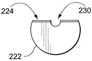
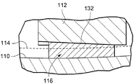
図1は、タービン構造の2つの段を縦断面で概略的に示す。図示した構造において、ほぼ部分円筒形又はU字状陥凹部10が、各ノズル根元12の受入れ溝14の底部に形成される。ケーシング18とノズル20との間で加圧ピン16をこの陥凹部内に挿入して、ノズルがそのプレツイスト位置になった状態でこれら部品を固定する。各ノズルを確実に固定しかつそのプレツイストを維持するために、本発明の実施形態では、加圧ピン16、116は、部分円筒形壁部分22、122、222と、漸増した、すなわち傾斜した又はステップ状になった壁部分24、124、224とを有する全体として楔形状になっている。
The pressure pin formed in accordance with the present invention presses the nozzle in a radial direction with sufficient force to maintain the design airfoil pre-twist to secure the nozzle radially inward to the carrier dovetail holding surface. FIG. 1 schematically shows two stages of a turbine structure in longitudinal section. In the structure shown, a substantially partially cylindrical or
図2に示す第1の実施形態では、加圧ピン116は、第1の挿入端部126から第2の基端部128まで実質的に連続的に傾斜して全体としてテーパが付いたすなわち楔形状のピン116を形成する壁部分124を有する。図3から分かるように、末端の挿入端部に隣接する加圧ピンの断面積は、基端部に隣接する加圧ピンの断面積よりも小さくなっている。壁部分124は、連続的にテーパが付けられた面として例示しているが、事実上連続的に傾斜した面を形成するような複数のステップ部を含む壁部分が、連続的に傾斜した面に機能的に等価なものとなる。
In the first embodiment shown in FIG. 2, the
ピンの基端部から末端部まで延びる部分円形リセスを形成するグルーブ130が、任意選択的に加圧ピンの長手方向に形成される。このグルーブにより、ピン材料をその元の面からスエージ加工又はすえ込み加工し、それによってピンとノズルと間の接触面積を増大させることができるようになる。さらに、このグルーブにより、例えば、ピン取外し工具(図示せず)の挿入が可能になって、ピンがそれぞれのノズル120の下方に完全に挿入されている場合であっても基端部から該ピンに係合させかつ該ピンを移動させることができるようになる。部分円形のグルーブ130を図示しているが、このグルーブの断面形状には制限がなく、本発明から逸脱することなくV形、矩形又はそれ以外のグルーブ構成とすることもできることを理解されたい。
A
分かると思うが、図2に示したテーパ付き加圧ピン116をノズル根元112とケーシングの根元溝(キャリアダブテール)114との間で陥凹部110内に挿入することにより、ノズルが溝底面から僅かに持ち上げられる。このことにより、設計エーロフォイルプレツイストを維持するのに十分な力で半径方向内向きに反動ノズルをキャリアダブテールの保持面に対して固定することになる。加圧ピンとそのそれぞれのノズルとの間の面対面接触を最大にするために、例示的な実施形態では、ノズル根元112の対応する部分は、加圧ピン116の壁部分124の傾斜にほぼ対応する傾斜面132を形成するように機械加工されており、加圧ピンの挿入により傾斜面対傾斜面の楔変位が生じるようになる。加圧ピンがその形状とケーシングに対する対応するノズルの固定を維持するようになるのを保証するために、例示的な実施形態では、加圧ピンは、鋼で作られる。
As can be seen, the
本発明の別の実施形態が図4〜図5及び図7に示されており、テーパ付きすなわち実質的に連続的に傾斜した面ではなく、壁部分224は、分離したステップ状部分を含む。図示した実施形態では、ピン216の全長に沿って単一のステップ部が形成される。より具体的には、この目的のために、加圧ピンは、該ピンの長手方向軸線に対してほぼ平行になった、各端部226、228に隣接する平坦なノズル係合面234、236を形成するように機械加工され、また加圧ピン216は、平行面226、228間に傾斜移行部すなわちステップ部238を形成するように機械加工される。点線240で示すように、平坦面226、228間のオフセット量は制限される。さらに図示するように、ノズル根元にカットアウト部242を設けて、ピンの挿入を容易にすることができる。
Another embodiment of the present invention is shown in FIGS. 4-5 and 7, wherein the
ピン216の基端部228から末端部226まで延びる部分円形リセスを形成するグルーブ230が、任意選択的に加圧ピンの長手方向に形成される。最初に記載した実施形態の場合ように、グルーブ230は、ピン材料をその元の面からスエージ加工又はすえ込み加工し、それによってピンとノズルと間の接触面積を増大させることができるようにするために設けられる。さらに、このグルーブにより、例えば、ピン取外し工具(図示せず)の挿入が可能になって、ピンがそれぞれのノズル212の下方に完全に挿入されている場合であっても基端部から該ピンに係合させかつ該ピンを移動させることができるようになる。上述のように、部分円形のグルーブ230をピン回収用として図示しているが、このグルーブの断面形状には制限がなく、本発明から逸脱することなくV形、矩形又はそれ以外のグルーブ構成とすることもできることを理解されたい。
A
分かると思うが、図4に示したテーパ付き加圧ピン216をノズル根元212とケーシングの根元溝214との間で陥凹部210内に挿入することにより、ノズルがダブテール溝214の底面から僅かに持ち上げられてノズルがその所定のプレツイスト構成において効果的に固定されるようになる。今一度言うが、加圧ピンがその形状とケーシングに対する対応するノズルの固定を維持するようになるのを保証するために、例示的な実施形態では、加圧ピンは、鋼で作られる。
As can be seen, by inserting the
上述したように、連続的に傾斜した面及び単一のステップ状の面を、本発明の実施形態として示したが、傾斜面は、連続的に傾斜している必要はなく一連の分離したステップ部として形成することもできる。さらに、ステップ部の分離した平坦面226、228は、図4に示すように、それ自体をピンの長手方向軸線に対してほぼ平行な面として形成するか又はそれ自体を傾斜させることができる。さらに、図示した実施形態では、分離したステップ部間の移行部238は、傾斜面として設けられているが、別の実施形態では、複数の分離しかつほぼ垂直な半径方向ステップ部を設け、それによって、ピンの断面積を末端部から基端部まで連続的に又は段階的に増大させることができる。
As described above, although a continuously inclined surface and a single stepped surface have been shown as an embodiment of the present invention, the inclined surface need not be continuously inclined but a series of discrete steps. It can also be formed as a part. Further, the separated
現在最も実用的かつ好ましい実施形態であると考えられるものについて本発明を説明してきたが、本発明は開示した実施形態に限定されるべきものでなく、また特許請求の範囲に記載した参照符号は、本発明の技術的範囲を狭めることを意図するものではなくそれらを容易に理解するためのものであることを理解されたい。 Although the present invention has been described in what is presently considered to be the most practical and preferred embodiments, the present invention should not be limited to the disclosed embodiments, and the reference signs in the claims are not It should be understood that the present invention is not intended to narrow the scope of the present invention, but is intended to facilitate understanding thereof.
10、110、210 陥凹部
12、112、212 根元
14、114、214 環状の溝
16、116、216 加圧ピン
18 タービンケーシング
20 固定ブレード
22、122、222 部分周壁部分
24、124、224 漸増壁部分
130、230 グルーブ
10, 110, 210
Claims (10)
複数の列の形態で複数の固定ブレード(20)を、列内の各固定ブレードが根元(12、112、212)とエーロフォイル部分とを有しかつ前記根元によってタービンケーシング(18)に形成された環状の溝(14、114、214)内に取付けられ、各前記環状の取付け溝が2つの対向する側壁と底壁とを有し、前記固定ブレードの根元及び前記取付け溝の壁の少なくとも1つが陥凹部(10、110、210)を形成した状態で、配置する段階と、
全体として楔形状となるように断面形状が前記陥凹部(10、110、210)の断面形状にほぼ対応した部分周壁部分(22、122、222)と漸増壁部分(24、124、224)とを含む加圧ピン(16、116、216)を各前記根元と溝との間で前記陥凹部内に挿入し、それによって前記固定ブレード根元を前記ケーシングに楔止めする段階と、
を含む方法。 A method of installing a stationary blade of a turbine,
A plurality of stationary blades (20) in the form of a plurality of rows, each stationary blade in the row having a root (12 , 112 , 212) and an airfoil portion and formed by said root in a turbine casing (18) Mounted in the annular groove (14 , 114 , 214), each annular attachment groove having two opposing side walls and a bottom wall, the root of the stationary blade and at least one of the walls of the attachment groove Placing the recesses with the depressions (10 , 110 , 210) formed;
A partial peripheral wall portion (22 , 122 , 222) and a gradually increasing wall portion (24 , 124 , 224) whose cross-sectional shape substantially corresponds to the cross-sectional shape of the recessed portion (10 , 110 , 210) so as to form a wedge shape as a whole; Inserting a pressure pin (16 , 116 , 216) comprising: between each said root and groove into said recess, thereby wedged said fixed blade root to said casing;
Including methods.
前記ロータの周りで同軸に支持されかつ前記回転ブレードの列と交互する列の形態で配置された複数の固定ブレードすなわちノズル(20)を有する固定ケーシング(19)と、を含み、
前記固定ブレードの少なくとも幾つかが、前記固定ケーシングの内面から延びるフォイル部分(20)と前記固定ケーシングの対応する溝(14、114、214)内に受けられる根元(12、112、212)を備えたベース部分とを含み、
前記固定ブレードの根元及び前記固定ケーシングの溝の少なくとも1つが、該固定ブレードの根元と溝との間に空間を形成する陥凹部(10、110、210)を含み、
加圧ピン(16、116、216)が、全体として楔形状になるように断面形状が前記陥凹部の断面形状にほぼ対応した部分周壁部分(22、122、222)と漸増壁部分(24、124、224)とを含み、前記陥凹部によって形成された空間内に配置されて前記ケーシングと根元とを相互結合している、
タービン構造。 A rotor having a plurality of rotating blades or buckets attached thereto, the blades being mounted in rows such that the blades extend radially outward from an outer surface thereof;
A fixed casing (19) having a plurality of fixed blades or nozzles (20) supported coaxially around the rotor and arranged in alternating rows with the rows of rotating blades;
At least some of the fixed blades include a foil portion (20) extending from the inner surface of the fixed casing and a root (12 , 112 , 212) received in a corresponding groove (14 , 114 , 214) of the fixed casing. Including a base portion,
At least one of the root of the stationary blade and the groove of the stationary casing includes a recess (10 , 110 , 210) forming a space between the root of the stationary blade and the groove;
The partial peripheral wall portions (22 , 122 , 222) and the gradually increasing wall portions (24,,) whose cross-sectional shape substantially corresponds to the cross-sectional shape of the recessed portion so that the pressure pins (16 , 116 , 216) have a wedge shape as a whole . 124 , 224), and disposed within the space formed by the recess to interconnect the casing and the root,
Turbine structure.
The turbine structure according to claim 6, wherein the partial peripheral wall portion has a partial cylindrical shape.
Applications Claiming Priority (1)
| Application Number | Priority Date | Filing Date | Title |
|---|---|---|---|
| US10/707,167 US6908279B2 (en) | 2003-11-25 | 2003-11-25 | Method of installing stationary blades of a turbine and turbine structure having a radial loading pin |
Publications (3)
| Publication Number | Publication Date |
|---|---|
| JP2005155633A JP2005155633A (en) | 2005-06-16 |
| JP2005155633A5 JP2005155633A5 (en) | 2008-01-17 |
| JP4624766B2 true JP4624766B2 (en) | 2011-02-02 |
Family
ID=34590818
Family Applications (1)
| Application Number | Title | Priority Date | Filing Date |
|---|---|---|---|
| JP2004340298A Active JP4624766B2 (en) | 2003-11-25 | 2004-11-25 | Method for mounting turbine stationary blades and turbine structure with radial pressure pins |
Country Status (5)
| Country | Link |
|---|---|
| US (1) | US6908279B2 (en) |
| JP (1) | JP4624766B2 (en) |
| KR (1) | KR100936566B1 (en) |
| CN (1) | CN1621661B (en) |
| DE (1) | DE102004057025B4 (en) |
Cited By (1)
| Publication number | Priority date | Publication date | Assignee | Title |
|---|---|---|---|---|
| JP2013122221A (en) * | 2011-12-12 | 2013-06-20 | Toshiba Corp | Stationary blade cascade, assembling method of stationary blade cascade, and steam turbine |
Families Citing this family (14)
| Publication number | Priority date | Publication date | Assignee | Title |
|---|---|---|---|---|
| US7645117B2 (en) * | 2006-05-05 | 2010-01-12 | General Electric Company | Rotary machines and methods of assembling |
| US7854583B2 (en) * | 2007-08-08 | 2010-12-21 | Genral Electric Company | Stator joining strip and method of linking adjacent stators |
| US8047778B2 (en) * | 2009-01-06 | 2011-11-01 | General Electric Company | Method and apparatus for insuring proper installation of stators in a compressor case |
| US8118550B2 (en) * | 2009-03-11 | 2012-02-21 | General Electric Company | Turbine singlet nozzle assembly with radial stop and narrow groove |
| US9133732B2 (en) | 2010-05-27 | 2015-09-15 | Siemens Energy, Inc. | Anti-rotation pin retention system |
| CH704001A1 (en) * | 2010-10-26 | 2012-04-30 | Alstom Technology Ltd | Guide vane arrangement for use between housing/cylinder and rotor casing of axial compressor, has guide vanes resiliently arranged with its bases at housing/cylinder in guide vane longitudinal direction |
| JP5342579B2 (en) * | 2011-02-28 | 2013-11-13 | 三菱重工業株式会社 | Stator blade unit of rotating machine, method of manufacturing stator blade unit of rotating machine, and method of coupling stator blade unit of rotating machine |
| US9045984B2 (en) | 2012-05-31 | 2015-06-02 | United Technologies Corporation | Stator vane mistake proofing |
| JP6082193B2 (en) * | 2012-06-20 | 2017-02-15 | 株式会社Ihi | Wing connection structure and jet engine using the same |
| US20140072419A1 (en) * | 2012-09-13 | 2014-03-13 | Manish Joshi | Rotary machines and methods of assembling |
| CN102966382B (en) * | 2012-11-30 | 2014-11-26 | 上海电气电站设备有限公司 | Stator blade assembly method for steam turbine generator |
| JP6185783B2 (en) * | 2013-07-29 | 2017-08-23 | 三菱日立パワーシステムズ株式会社 | Axial flow compressor, gas turbine equipped with axial flow compressor, and method for remodeling axial flow compressor |
| US9828866B2 (en) * | 2013-10-31 | 2017-11-28 | General Electric Company | Methods and systems for securing turbine nozzles |
| US11655043B2 (en) | 2019-05-16 | 2023-05-23 | Duxion Motors, Inc. | Electric aircraft propulsion system |
Citations (3)
| Publication number | Priority date | Publication date | Assignee | Title |
|---|---|---|---|---|
| JPH11506814A (en) * | 1995-12-20 | 1999-06-15 | アーベーベー・パテント・ゲーエムベーハー | Guide device for turbine having guide blade carrier and method of manufacturing this device |
| JP2000337103A (en) * | 1999-05-26 | 2000-12-05 | Mitsubishi Heavy Ind Ltd | Integral shroud stationary blade |
| JP2005146896A (en) * | 2003-11-11 | 2005-06-09 | Toshiba Corp | Nozzle diaphragm of steam turbine and steam turbine plant |
Family Cites Families (16)
| Publication number | Priority date | Publication date | Assignee | Title |
|---|---|---|---|---|
| US2225769A (en) * | 1939-03-17 | 1940-12-24 | Westinghouse Electric & Mfg Co | Turbine blade |
| US2410588A (en) * | 1942-06-23 | 1946-11-05 | Northrop Aircraft Inc | Turbine blade and assembly thereof |
| CS174516B1 (en) * | 1974-09-26 | 1977-04-29 | ||
| US4175755A (en) * | 1978-12-11 | 1979-11-27 | Carrier Corporation | Mechanical seal assembly |
| US4444544A (en) | 1980-12-19 | 1984-04-24 | United Technologies Corporation | Locking of rotor blades on a rotor disk |
| US4819313A (en) * | 1988-06-03 | 1989-04-11 | Westinghouse Electric Corp. | Method of salvaging stationary blades of a steam turbine |
| US5088894A (en) * | 1990-05-02 | 1992-02-18 | Westinghouse Electric Corp. | Turbomachine blade fastening |
| JPH06212905A (en) * | 1993-01-19 | 1994-08-02 | Fuji Electric Co Ltd | Fixed blade in moving blade cascade |
| DE4430636C2 (en) * | 1994-08-29 | 1997-01-23 | Mtu Muenchen Gmbh | Device for fixing the rotor blades and eliminating rotor imbalances in compressors or turbines of gas turbine engines with axial flow |
| JPH10103010A (en) * | 1996-10-02 | 1998-04-21 | Mitsubishi Heavy Ind Ltd | Turbine stationary blade |
| DE19654471B4 (en) * | 1996-12-27 | 2006-05-24 | Alstom | Rotor of a turbomachine |
| US6190131B1 (en) | 1999-08-31 | 2001-02-20 | General Electric Co. | Non-integral balanced coverplate and coverplate centering slot for a turbine |
| JP4040922B2 (en) * | 2001-07-19 | 2008-01-30 | 株式会社東芝 | Assembly type nozzle diaphragm and its assembly method |
| GB2384829A (en) * | 2002-01-31 | 2003-08-06 | Rolls Royce Plc | Casing arrangement |
| US6786699B2 (en) * | 2002-06-26 | 2004-09-07 | General Electric Company | Methods of assembling airfoils to turbine components and assemblies thereof |
| US6722848B1 (en) * | 2002-10-31 | 2004-04-20 | General Electric Company | Turbine nozzle retention apparatus at the carrier horizontal joint face |
-
2003
- 2003-11-25 US US10/707,167 patent/US6908279B2/en not_active Expired - Lifetime
-
2004
- 2004-11-24 KR KR1020040096971A patent/KR100936566B1/en active IP Right Grant
- 2004-11-25 DE DE102004057025A patent/DE102004057025B4/en active Active
- 2004-11-25 JP JP2004340298A patent/JP4624766B2/en active Active
- 2004-11-25 CN CN200410096207XA patent/CN1621661B/en active Active
Patent Citations (3)
| Publication number | Priority date | Publication date | Assignee | Title |
|---|---|---|---|---|
| JPH11506814A (en) * | 1995-12-20 | 1999-06-15 | アーベーベー・パテント・ゲーエムベーハー | Guide device for turbine having guide blade carrier and method of manufacturing this device |
| JP2000337103A (en) * | 1999-05-26 | 2000-12-05 | Mitsubishi Heavy Ind Ltd | Integral shroud stationary blade |
| JP2005146896A (en) * | 2003-11-11 | 2005-06-09 | Toshiba Corp | Nozzle diaphragm of steam turbine and steam turbine plant |
Cited By (1)
| Publication number | Priority date | Publication date | Assignee | Title |
|---|---|---|---|---|
| JP2013122221A (en) * | 2011-12-12 | 2013-06-20 | Toshiba Corp | Stationary blade cascade, assembling method of stationary blade cascade, and steam turbine |
Also Published As
| Publication number | Publication date |
|---|---|
| DE102004057025B4 (en) | 2012-06-14 |
| JP2005155633A (en) | 2005-06-16 |
| US20050111973A1 (en) | 2005-05-26 |
| CN1621661B (en) | 2011-12-28 |
| US6908279B2 (en) | 2005-06-21 |
| CN1621661A (en) | 2005-06-01 |
| KR100936566B1 (en) | 2010-01-13 |
| KR20050050574A (en) | 2005-05-31 |
| DE102004057025A1 (en) | 2005-06-23 |
Similar Documents
| Publication | Publication Date | Title |
|---|---|---|
| JP4624766B2 (en) | Method for mounting turbine stationary blades and turbine structure with radial pressure pins | |
| JP4406259B2 (en) | Continuous radial biasing device and method for a reaction bucket of a steam turbine | |
| CA1318852C (en) | Apparatus for locking side entry blades into a rotor | |
| US6450769B2 (en) | Blade assembly with damping elements | |
| EP0431766B1 (en) | Improved attachment of a gas turbine engine blade to a turbine rotor disc | |
| JP5654773B2 (en) | Low stress circumferential dovetail mounting device for rotor blades | |
| KR20040097938A (en) | Vibration damper assembly for the buckets of a turbine | |
| KR100227051B1 (en) | Turbine blade assembly | |
| JP5596223B2 (en) | Fixed assembly for blades of an axial-flow turbomachine and method for manufacturing such an assembly | |
| EP3093439B1 (en) | Damper system for a turbine | |
| US5431543A (en) | Turbine blade locking assembly | |
| US7442011B2 (en) | Locking device for turbine blades | |
| EP0280246B1 (en) | Method of assembly of a blade arrangement for a steam turbine | |
| US20090077795A1 (en) | Replaceable Staking Insert | |
| JP5337349B2 (en) | Apparatus comprising a ring for holding a flange on a rotor disk and turbomachine turbine and turbomachine including the apparatus | |
| US7309215B2 (en) | Axial locking device for turbine blades | |
| JP2003314206A (en) | Bladed rotor and blade therefor | |
| US10047615B2 (en) | Method of mounting rotor blades on a rotor disk, and clamping device for performing such a method | |
| EP2322761B1 (en) | Bladed rotor wheel | |
| JP4929316B2 (en) | Rotating body | |
| JPS6310283B2 (en) | ||
| EP2463042A1 (en) | Assembly jig for pins for power transmission chain | |
| JP4439239B2 (en) | Turbine nozzle holding device at horizontal joint surface of support | |
| WO2012052358A1 (en) | Root adapting device for and method of attaching a blade in a recess of a rotatable shaft of a steam turbine | |
| JP2020534466A (en) | Wing unit assembly |
Legal Events
| Date | Code | Title | Description |
|---|---|---|---|
| A521 | Request for written amendment filed |
Free format text: JAPANESE INTERMEDIATE CODE: A523 Effective date: 20071121 |
|
| A621 | Written request for application examination |
Free format text: JAPANESE INTERMEDIATE CODE: A621 Effective date: 20071121 |
|
| A131 | Notification of reasons for refusal |
Free format text: JAPANESE INTERMEDIATE CODE: A131 Effective date: 20100601 |
|
| A521 | Request for written amendment filed |
Free format text: JAPANESE INTERMEDIATE CODE: A523 Effective date: 20100707 |
|
| RD02 | Notification of acceptance of power of attorney |
Free format text: JAPANESE INTERMEDIATE CODE: A7422 Effective date: 20100707 |
|
| RD04 | Notification of resignation of power of attorney |
Free format text: JAPANESE INTERMEDIATE CODE: A7424 Effective date: 20100707 |
|
| TRDD | Decision of grant or rejection written | ||
| A01 | Written decision to grant a patent or to grant a registration (utility model) |
Free format text: JAPANESE INTERMEDIATE CODE: A01 Effective date: 20101005 |
|
| A01 | Written decision to grant a patent or to grant a registration (utility model) |
Free format text: JAPANESE INTERMEDIATE CODE: A01 |
|
| A61 | First payment of annual fees (during grant procedure) |
Free format text: JAPANESE INTERMEDIATE CODE: A61 Effective date: 20101104 |
|
| R150 | Certificate of patent or registration of utility model |
Ref document number: 4624766 Country of ref document: JP Free format text: JAPANESE INTERMEDIATE CODE: R150 Free format text: JAPANESE INTERMEDIATE CODE: R150 |
|
| FPAY | Renewal fee payment (event date is renewal date of database) |
Free format text: PAYMENT UNTIL: 20131112 Year of fee payment: 3 |
|
| R250 | Receipt of annual fees |
Free format text: JAPANESE INTERMEDIATE CODE: R250 |
|
| R250 | Receipt of annual fees |
Free format text: JAPANESE INTERMEDIATE CODE: R250 |
|
| R250 | Receipt of annual fees |
Free format text: JAPANESE INTERMEDIATE CODE: R250 |
|
| R250 | Receipt of annual fees |
Free format text: JAPANESE INTERMEDIATE CODE: R250 |
|
| R250 | Receipt of annual fees |
Free format text: JAPANESE INTERMEDIATE CODE: R250 |
|
| R250 | Receipt of annual fees |
Free format text: JAPANESE INTERMEDIATE CODE: R250 |
|
| R250 | Receipt of annual fees |
Free format text: JAPANESE INTERMEDIATE CODE: R250 |
|
| R250 | Receipt of annual fees |
Free format text: JAPANESE INTERMEDIATE CODE: R250 |
|
| R250 | Receipt of annual fees |
Free format text: JAPANESE INTERMEDIATE CODE: R250 |
|
| R250 | Receipt of annual fees |
Free format text: JAPANESE INTERMEDIATE CODE: R250 |
|
| S111 | Request for change of ownership or part of ownership |
Free format text: JAPANESE INTERMEDIATE CODE: R313113 |
|
| R350 | Written notification of registration of transfer |
Free format text: JAPANESE INTERMEDIATE CODE: R350 |