JP4624663B2 - Stator manufacturing method - Google Patents
Stator manufacturing method Download PDFInfo
- Publication number
- JP4624663B2 JP4624663B2 JP2003411276A JP2003411276A JP4624663B2 JP 4624663 B2 JP4624663 B2 JP 4624663B2 JP 2003411276 A JP2003411276 A JP 2003411276A JP 2003411276 A JP2003411276 A JP 2003411276A JP 4624663 B2 JP4624663 B2 JP 4624663B2
- Authority
- JP
- Japan
- Prior art keywords
- coil
- stator
- stator core
- insulation
- manufacturing
- Prior art date
- Legal status (The legal status is an assumption and is not a legal conclusion. Google has not performed a legal analysis and makes no representation as to the accuracy of the status listed.)
- Expired - Fee Related
Links
Images


Landscapes
- Insulation, Fastening Of Motor, Generator Windings (AREA)
- Manufacture Of Motors, Generators (AREA)
Description
本発明は、回転子と固定子とから構成される回転電機の製造方法に関し、特に、固定子の製造方法に関する。 The present invention relates to a method for manufacturing a rotating electrical machine including a rotor and a stator, and more particularly to a method for manufacturing a stator.
従来、回転子と固定子とから構成される回転電機において、回転電機の固定子の製造方法は、まず、打ち抜いた珪素鋼板を積層して固定子鉄心を製造する。そして、製造した固定子鉄心に絶縁紙を挿入する。別途コイルを環状に巻回しておく。つづいて、巻回したコイルを固定子鉄心に挿入する。そして、固定子鉄心の各相間に絶縁紙を組み付ける。その後、コイルエンド部を予め定められた形状に成形する。そして、端末部において結線処理等を行なう工程を経て、固定子は製造される。 Conventionally, in a rotating electrical machine composed of a rotor and a stator, the stator manufacturing method of the rotating electrical machine first manufactures a stator core by stacking punched silicon steel sheets. Then, insulating paper is inserted into the manufactured stator core. Separately, the coil is wound in an annular shape. Next, the wound coil is inserted into the stator core. Then, insulating paper is assembled between each phase of the stator core. Thereafter, the coil end portion is formed into a predetermined shape. And a stator is manufactured through the process of performing a connection process etc. in a terminal part.
固定子の製造方法としては、以下のような公報に開示されている。 A method for manufacturing a stator is disclosed in the following publications.
特許文献1(特開2003−244907号公報)は、含浸性が悪い高熱伝導用ワニスを使用させているときでも、コイルの隙間にワニスを含浸させて、コイル間の熱伝導率、コイル、ステータ間の熱伝導率を向上させ、抜熱性を向上させる電動機の製造方法を開示する。この電動機の製造方法は、電動機のステータスロットに巻線を挿入して電動機を製造する方法である。電動機の製造方法は、ステータスロットに挿入されるスロット絶縁紙をステータスロットのティース部よりステータ内周側に突出させた状態で、スロット絶縁紙内に巻線を挿入させる。その後、巻線にワニスを滴下含浸させながら、ステータ内側に挿入したコイル圧縮冶具で、スロット絶縁紙の突出部分を内側に折り曲げさせ、巻線を圧縮成形させる。 Patent Document 1 (Japanese Patent Laid-Open No. 2003-244907) discloses that even when a highly heat conductive varnish with poor impregnation is used, the gap between the coils is impregnated with the varnish, and the thermal conductivity between the coils, the coil, and the stator The manufacturing method of the electric motor which improves the thermal conductivity in the meantime and improves heat removal is disclosed. This method for manufacturing an electric motor is a method for manufacturing an electric motor by inserting a winding into a status lot of the electric motor. In the method of manufacturing the electric motor, the winding is inserted into the slot insulating paper in a state where the slot insulating paper inserted into the status lot is protruded from the tooth portion of the status lot toward the inner periphery of the stator. Thereafter, while the varnish is dripped and impregnated in the winding, the protruding portion of the slot insulating paper is bent inward with a coil compression jig inserted inside the stator, and the winding is compression molded.
この特許文献1に開示された電動機の製造方法によると、含浸性が悪い高熱伝導用ワニスを使用しているときでも、コイルの隙間にワニスを含浸させることができる。さらに、スロット占積率を向上させることができる。これによってコイルの隙間にワニスを充填させて、コイル間の熱伝導率と、コイルおよびステータ間の熱伝導率とを向上させる。すなわち、抜熱性を向上させることができる。さらに、コイルの隙間を小さくさせて、コイル断面積をアップさせることにより、銅損を低減させることができる。そして、ウェッジなどを不要にさせて、電動機を製造する際の部品点数、工程数を低減させる。すなわち、製造コストを低減させることができる。
しかしながら、特許文献1に開示された電動機の製造方法においては、絶縁における重要部品であるコイルに対して、1)ノズルを介して巻枠への組み付け、2)挿入冶具でのコイル挿入、3)コイルエンド成形冶具での成形、などの絶縁被覆へのダメージの大きい加工を工程のさまざまな箇所で行なっているという問題があった。 However, in the method of manufacturing an electric motor disclosed in Patent Document 1, for a coil that is an important component in insulation, 1) assembly to a winding frame through a nozzle, 2) coil insertion with an insertion jig, 3) There has been a problem that processing with a large damage to the insulation coating, such as forming with a coil end forming jig, is performed at various points in the process.
一般に同期モータの固定子の製造方法は、図20に示すような手順で行なわれる。 In general, a method for manufacturing a stator of a synchronous motor is performed according to a procedure as shown in FIG.
ステップ(以下、ステップをSと略して記載する。)2000にて、固定子鉄心は、電磁鋼板を予め定められた形状にプレス成形された後に、所定の枚数だけ積層して形成される。S2100にて、固定子鉄心のスロットに絶縁紙が組み付けられる。 In step (hereinafter step is abbreviated as S) 2000, the stator core is formed by laminating a predetermined number of sheets after the electromagnetic steel sheets are press-formed into a predetermined shape. In S2100, insulating paper is assembled into the slots of the stator core.
一方、S2200にて、コイルをたとえば、エナメル等の絶縁材料で絶縁被覆された導体の巻線で構成するとすると、コイルの巻線は、環状に巻回される。そして、S2300にて、巻回されたコイルを固定子鉄心のスロット間のティースに組み付ける。 On the other hand, in S2200, if the coil is composed of a conductor winding coated with an insulating material such as enamel, the coil winding is wound in an annular shape. In S2300, the wound coil is assembled to the teeth between the slots of the stator core.
S2400にて、固定子鉄心に挿入したコイルを成形して、固定子鉄心へのコイルの巻着が完了する。S2500にて、巻着したコイルに対して結線処理を施す。S2600にて、固定子に組み付けられた絶縁紙およびコイルに付着された絶縁材料の傷つきを検査する。S2700にて、製造された固定子の不良品の検査等の最終検査を行なう。 In S2400, the coil inserted into the stator core is formed, and the winding of the coil around the stator core is completed. In S2500, a wire connection process is performed on the wound coil. In S2600, the insulating paper attached to the stator and the insulating material attached to the coil are inspected for damage. In S2700, final inspection such as inspection of defective products of the manufactured stator is performed.
上述したような手順で行なう場合、固定子鉄心にコイルを組み付ける際に、固定子鉄心に組み付けられた絶縁紙、あるいは、コイルに付着した絶縁材料は、コイルの組み付けの前に予め固定子鉄心に組み付けられている。そのため、コイルを固定子鉄心に組み付ける際にコイルの張力や挿入時の圧力などの組み付け時に、絶縁材料に対してさまざまな力が加わる。そのことにより、絶縁紙あるいは絶縁材料がはがれるといった問題が起こる。 When performing the procedure as described above, when assembling the coil to the stator core, the insulating paper assembled to the stator core or the insulating material attached to the coil is preliminarily attached to the stator core before the coil is assembled. It is assembled. For this reason, when the coil is assembled to the stator core, various forces are applied to the insulating material at the time of assembling the coil tension or the pressure at the time of insertion. This causes a problem that the insulating paper or the insulating material is peeled off.
また、絶縁紙を組み付けた状態の固定子鉄心、または、絶縁材料が付着されたコイルは、部品単体の精度が悪い。そのため、機械によるコイルの固定子鉄心への自動組み付けは、困難であった。 In addition, the stator core with the insulating paper assembled or the coil to which the insulating material is attached has poor accuracy of a single component. Therefore, automatic assembly of the coil to the stator core by a machine has been difficult.
さらに、固定子の製造工程において絶縁材料は絶縁性能の他に強度を確保する必要がある。そのため、耐熱性、耐電圧のより高い、たとえば、セラミックスやガラス繊維等の無機系の絶縁材料の使用ができない。すなわち、絶縁材料の選択が制限されるため、回転電機の耐熱性、耐電圧を向上させることが困難であるという問題があった。 Further, in the stator manufacturing process, the insulating material needs to ensure strength in addition to the insulating performance. Therefore, it is impossible to use an inorganic insulating material having higher heat resistance and voltage resistance, such as ceramics and glass fiber. That is, since the selection of the insulating material is limited, there is a problem that it is difficult to improve the heat resistance and voltage resistance of the rotating electrical machine.
本発明は、上述したような課題を解決するためになされたものであって、その目的は、絶縁品質を向上させた回転電機の固定子の製造方法を提供することである。 The present invention has been made to solve the above-described problems, and an object of the present invention is to provide a method of manufacturing a stator of a rotating electrical machine with improved insulation quality.
第1の発明に係る固定子の製造方法は、回転子と固定子とから構成される回転電機の固定子の製造方法であって、前記固定子は、複数のティースを有する固定子鉄心と、前記ティースに巻着された金属平板からなるコイルであってコイルエンド部の断面積が前記固定子鉄心のティース間のスロット内に配置される部分の断面積よりも大きく形成されるコイルとを含み、前記固定子の製造方法は、前記固定子鉄心を製造するとともに、前記コイルを、前記ティースに巻着されたときに前記ティースとの間に隙間が生じるように設計された形状に形成し、次に前記コイルを前記ティースに巻着し、そして前記固定子鉄心に巻着された前記コイルに対して絶縁処理するものであり、前記絶縁処理では、前記固定子鉄心と前記コイルとの間、前記コイルと、前記コイルが巻着された前記ティースと隣接するティースに巻着されたコイルとの間、および、結線処理された前記コイルの結線処理部のいずれも未だ絶縁処理されていない3ヶ所を同時に絶縁材料で埋めるようにして絶縁する。
A method for manufacturing a stator according to a first aspect of the present invention is a method for manufacturing a stator of a rotating electric machine including a rotor and a stator, and the stator includes a stator core having a plurality of teeth, A coil made of a metal flat plate wound around the teeth, wherein the coil end portion has a cross-sectional area larger than a cross-sectional area of a portion disposed in a slot between the teeth of the stator core. The stator manufacturing method manufactures the stator core, and forms the coil in a shape designed so that a gap is formed between the teeth when wound around the teeth. Next, the coil is wound around the teeth, and the coil wound around the stator core is subjected to insulation treatment. In the insulation treatment, between the stator core and the coil, The carp If, between the coil in which the coil is wound around the teeth adjacent to the tooth that is wound around, and the three locations none yet insulated the connection processing portion of the coil which is the connection processing at the same time Insulate by filling with insulating material .
第1の発明によると、コイルを形成するステップにて、コイルは、固定子鉄心が有するティースの形状に合致する形状(たとえば、ティースとコイルとの間に隙間を有するように設計された形状)に形成される。コイルをティースに巻着させるステップにて、コイルは、ティースに巻着される。処理ステップにて、固定子鉄心に巻着されたコイルに対して絶縁処理を施す。このように、固定子鉄心にコイルが巻着された後に、固定子鉄心のティースとコイルとの間の隙間に対して絶縁処理を行なうことにより、品質の高い絶縁処理を施すことができる。すなわち、コイルの巻着後に絶縁処理を施すため、固定子鉄心へのコイル組み付け時に固定子鉄心あるいは、コイルは、絶縁被覆されていない。そのため、コイルの組み付け時に絶縁被覆が傷つくことを回避することができる。したがって、絶縁処理は、高い絶縁品質を確保することができる。これにより、絶縁品質を向上させた回転電機の固定子の製造方法を提供することができる。また、固定子鉄心へのコイルの組み付け時においては、絶縁被覆されていないため、部品の精度が高い。そして、コイルの組み付け時に絶縁被覆の傷つきを考慮する必要がない。そのため、固定子鉄心へのコイルの組み付けの工程を自動化することができる。すなわち、固定子鉄心へのコイルの組み付け性が向上する。そして、組み付けたコイルの品質の安定が図れる。さらに、絶縁被覆の傷つきが起こらないため、固定子の中間検査として行なわれる絶縁検査の工程を省略することができる。そのため、固定子の製造時間の短縮が図れる。すなわち、固定子の製造コストの低減が図れる。
また、第1の発明によると、コイルが固定子鉄心に巻着された後に絶縁処理を施すため、固定子鉄心とコイルとの間、コイルと、コイルが巻着されたティースと隣接するティースに巻着されたコイルとの間、結線処理されたコイルの結線処理部の3ヶ所が同時に絶縁されるように処理することが可能になる。コイルの巻着後に絶縁処理を施すため、固定子鉄心へのコイル組み付け時に、固定子鉄心あるいはコイルは、絶縁被覆されていない。そのため、コイルの組み付け時に絶縁被覆が傷つくことを回避することができる。したがって、高い絶縁品質を確保することができる。また、上述した3ヶ所に対して同時に絶縁処理を行なうことにより、製造時間の短縮が図れる。そのため、固定子の製造コストの低減が図れる。
さらに、第1の発明によると、ティースに巻着されるコイルは、コイルエンド部の断面積が前記固定子鉄心のティース間のスロット内に配置される部分の断面積よりも大きく形成されるので、コイルエンド部とスロット内のコイル部分の断面積を同じとした場合に比べて、コイルエンド部を形成するコイルの体積が増加する。そのため、コイルエンド部における熱容量が向上する。スロット内のコイル部分に発熱した熱は、熱抵抗の殆どない同一ターンのコイルエンド部に伝達される。その結果、スロット内のコイル部分からコイルエンド部への放熱性が向上する。したがって、スペースの小さなスロット内のコイルにおいて電流密度を向上させることが可能となる。すなわち、電流密度が向上した分の固定子の小型化が可能となる。
According to the first invention, in the step of forming the coil, the coil has a shape that matches the shape of the teeth that the stator iron core has (for example, a shape that is designed to have a gap between the teeth and the coil). Formed. In the step of winding the coil around the teeth, the coil is wound around the teeth. In the processing step, an insulation process is performed on the coil wound around the stator core. As described above, after the coil is wound around the stator core, the insulation process is performed on the gap between the teeth of the stator core and the coil, whereby a high-quality insulation process can be performed. That is, since the insulation treatment is performed after the coil is wound, the stator core or the coil is not covered with the insulation when the coil is assembled to the stator core. Therefore, it is possible to avoid damage to the insulating coating during assembly of the coil. Therefore, the insulation process can ensure high insulation quality. Thereby, the manufacturing method of the stator of the rotary electric machine which improved insulation quality can be provided. In addition, when the coil is assembled to the stator core, since the insulation coating is not provided, the accuracy of the parts is high. And it is not necessary to consider the damage of an insulation coating at the time of the assembly | attachment of a coil. Therefore, the process of assembling the coil to the stator core can be automated. That is, the assembling property of the coil to the stator core is improved. In addition, the quality of the assembled coil can be stabilized. Furthermore, since the insulation coating is not damaged, an insulation inspection process performed as an intermediate inspection of the stator can be omitted. Therefore, the manufacturing time of the stator can be shortened. That is, the manufacturing cost of the stator can be reduced.
In addition, according to the first invention, in order to perform insulation treatment after the coil is wound around the stator core, the coil and the tooth adjacent to the tooth around which the coil is wound are disposed between the stator core and the coil. It is possible to perform processing so that three portions of the connection processing portion of the coil subjected to the connection processing are simultaneously insulated from the wound coil. Since the insulation treatment is performed after the coil is wound, the stator core or the coil is not covered with insulation when the coil is assembled to the stator core. Therefore, it is possible to avoid damage to the insulating coating during assembly of the coil. Therefore, high insulation quality can be ensured. In addition, the manufacturing time can be shortened by simultaneously performing the insulation treatment on the above-mentioned three locations. Therefore, the manufacturing cost of the stator can be reduced.
Furthermore, according to the first invention, the coil wound around the teeth is formed such that the cross-sectional area of the coil end portion is larger than the cross-sectional area of the portion disposed in the slot between the teeth of the stator core. The volume of the coil forming the coil end portion increases as compared with the case where the cross-sectional areas of the coil end portion and the coil portion in the slot are the same. Therefore, the heat capacity in the coil end portion is improved. The heat generated in the coil portion in the slot is transmitted to the coil end portion of the same turn having almost no thermal resistance. As a result, heat dissipation from the coil portion in the slot to the coil end portion is improved. Therefore, the current density can be improved in the coil in the slot having a small space. That is, the stator can be miniaturized as the current density is improved.
そして、上述したように固定子の絶縁被覆に対して製造工程におけるダメージを受けることがなくなるため、製造工程におけるダメージに対する絶縁材料の強度を確保する必要がなくなる。そのため、耐熱性、耐電圧のより高い絶縁材料を使用することができる。すなわち、回転電機の耐熱性、耐電圧を向上させることができる。 As described above, since the stator insulation coating is not damaged in the manufacturing process, it is not necessary to ensure the strength of the insulating material against the damage in the manufacturing process. Therefore, an insulating material with higher heat resistance and withstand voltage can be used. That is, the heat resistance and voltage resistance of the rotating electrical machine can be improved.
さらに、製造工程におけるダメージに対する絶縁品質、信頼性を確保する必要がなくなるために絶縁材料の選択が制限されることもなくなる。したがって、今まで製造工程におけるダメージに対する強度等が確保できないため使用できなかった無機系の材料(たとえば、セラミックス、ガラス繊維等)を絶縁材料として使用することができる。 Furthermore, since it is not necessary to ensure insulation quality and reliability against damage in the manufacturing process, selection of the insulation material is not restricted. Therefore, an inorganic material (for example, ceramics, glass fiber, etc.) that could not be used because the strength against damage in the manufacturing process cannot be ensured until now can be used as the insulating material.
第2の発明に係る固定子の製造方法においては、第1の発明の構成に加えて、前記絶縁処理では、前記絶縁材料を加圧してコイルに付着させることを含む。
In the method of manufacturing a stator according to the second invention, in addition to the configuration of the first invention, in the insulation process, comprises attaching the coils to pressurize the insulating material.
第2の発明によると、前記絶縁処理では、絶縁材料を加圧してコイルに付着させる。コイルが固定子鉄心に巻着された後に固定子鉄心とコイルとの間、コイルの導電部材同士の接触部、コイルと、コイルが巻着されたティースと隣接するティースに巻着されたコイルとの間、結線処理されたコイルの結線処理部の4ヶ所の中の少なくとも3箇所に対して、絶縁材料を加圧してコイルに付着させる。そのため、それぞれの箇所に絶縁材料を用いて絶縁処理を行なうことができる。
According to 2nd invention, in the said insulation process, an insulating material is pressurized and it adheres to a coil. After the coil is wound around the stator core, between the stator core and the coil, the contact portion between the conductive members of the coil, the coil, and the coil wound around the tooth around which the coil is wound In the meantime, an insulating material is pressurized and adhered to the coil at least at three of the four connection processing portions of the coil subjected to the connection processing. Therefore, an insulating process can be performed using an insulating material at each location.
第3の発明に係る固定子の製造方法においては、第1の発明の構成に加えて、前記絶縁処理では、前記絶縁材料をコイルに含浸させてコイルに付着させるステップを含む。
In the stator manufacturing method according to the third invention, in addition to the structure of the first invention, the insulating treatment includes a step of impregnating the coil with the insulating material and attaching it to the coil.
第3の発明によると、前記絶縁処理では、絶縁材料をコイルに含浸させてコイルに付着させる。コイルが固定子鉄心に巻着された後に固定子鉄心とコイルとの間、コイルの導電部材同士(たとえば、らせん形状に形成される金属平板同士)の接触部、コイルと、コイルが巻着されたティースと隣接するティースに巻着されたコイルとの間、結線処理されたコイルの結線処理部の4ヶ所の中の少なくとも3箇所に対して、コイルが巻着された固定子鉄心を絶縁材料に浸すいわゆる含浸により絶縁材料をコイルに付着させる。そのため、それぞれの箇所に対して絶縁材料を用いて絶縁処理を行なうことができる。
According to the third invention, in the insulation treatment, the coil is impregnated with an insulating material and adhered to the coil. After the coil is wound around the stator core, the contact portion between the stator core and the coil, the conductive members of the coil (for example, metal flat plates formed in a spiral shape), the coil, and the coil are wound. Between at least three of the connection processing portions of the coil that has been connected between the adjacent teeth and the coil that is wound around the adjacent teeth, the stator core around which the coils are wound is insulated. Insulating material is attached to the coil by so-called impregnation. Therefore, it is possible to perform an insulation process using an insulating material for each portion.
第4の発明に係る固定子の製造方法においては、第1または第3の発明の構成に加えて、前記絶縁処理では、真空雰囲気において前記絶縁材料をコイルに含浸させてコイルに付着させるステップを含む。
In the method of manufacturing a stator according to a fourth invention, in addition to the configuration of the first or third aspect, wherein an insulating process, the step of attaching the coil to the insulating material is impregnated into the coil in a vacuum atmosphere Including.
第4の発明によると、前記絶縁処理では、真空雰囲気において絶縁材料を含浸させて、コイルに付着させる。コイルが固定子鉄心に巻着された後に固定子鉄心とコイルとの間、コイルの導電部材同士(たとえば、らせん形状に形成される金属平板同士)の接触部、コイルと、コイルが巻着されたティースと隣接するティースに巻着されたコイルとの間、結線処理されたコイルの結線処理部の4ヶ所の中の少なくとも3箇所に対して、真空雰囲気において固定子鉄心に巻着されたコイルに絶縁材料を含浸させてコイルに付着させる。そのため、それぞれの箇所に対して絶縁材料を用いて絶縁処理を行なうことができる。
According to the fourth invention, in the insulating treatment , the insulating material is impregnated in a vacuum atmosphere and attached to the coil. After the coil is wound around the stator core, the contact portion between the stator core and the coil, the conductive members of the coil (for example, metal flat plates formed in a spiral shape), the coil, and the coil are wound. Coil wound around the stator core in a vacuum atmosphere with respect to at least three of the four connection processing portions of the coil that has been connected between the adjacent teeth and the coil wound around the adjacent teeth. Is impregnated with an insulating material and attached to the coil. Therefore, it is possible to perform an insulation process using an insulating material for each portion.
以下、図面を参照しつつ、本発明の実施の形態に係る回転電機の固定子の製造方法について説明する。以下の説明では、同一の部品には同一の符号を付してある。それらの名称および機能も同じである。したがってそれらについての詳細な説明は繰返さない。 Hereinafter, a method for manufacturing a stator of a rotating electrical machine according to an embodiment of the present invention will be described with reference to the drawings. In the following description, the same parts are denoted by the same reference numerals. Their names and functions are also the same. Therefore, detailed description thereof will not be repeated.
<第1の実施の形態>
本実施の形態に係る固定子の製造方法を説明するにあたり、まず、この固定子の製造方法により製造された回転電機の固定子の構造について同期モータの固定子を一例として説明する。
<First Embodiment>
In describing the stator manufacturing method according to the present embodiment, first, the structure of the stator of the rotating electrical machine manufactured by the stator manufacturing method will be described by taking the stator of the synchronous motor as an example.
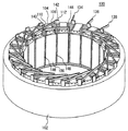
同期モータは、固定子と永久磁石からなる回転子とから構成される。固定子100は、図1に示すように固定子鉄心(以下の説明において、「ステータコア」は、「固定子鉄心」と同じ意味を示す。)102と、コイル112と、バスバー110と、バスバー位置決めブロック104と、渡り部材106とから構成される。
A synchronous motor is comprised from the rotor which consists of a stator and a permanent magnet. As shown in FIG. 1, the
ステータコア102は、複数の電磁鋼板が積層され中空円筒形状を形成している。そして、ステータコア102は、同期モータの回転軸に平行な方向に所定数の溝(以下、スロットという)を有している。所定数のスロットは、極数に対応した個数を有している。極数は、特に限定されるものではないが本実施の形態においては、たとえば、21とする。また、スロット間には、歯部(以下、ティースという。)108を有している。ティースの個数もスロットと同様に極数に対応している。したがって、本実施の形態において、極数が21のステータコア102は、21個のティース間に21個のスロットが形成されている。
The
そして、ティース108には、端部が巻着可能に開いた複数の予め定められた形状の導体の金属平板(図示せず)が積層された金属導体である積層体コイル(図示せず)が同期モータの回転軸に平行な方向に、ティース108を跨ぐようにして、ティース108の両脇のスロットに挿入されている。そして、ティース108の両脇のスロットにおいては、同期モータの径方向に複数の積層体コイルが挿入されている。挿入される積層体コイルの数は、特に限定されるものではないが、たとえば、本実施の形態においては、ティース108を跨ぐようにして径方向に10個の積層体コイルが挿入されている。
The
積層体コイルの開放端部は、直線形状の導体であるバスバー110の両端部と接合される。このとき、バスバー110の一方端部は、積層体コイルの開放端部の一方と接合される。そして、バスバー110の他方端部は、積層体コイルに隣接する積層体コイルに有する開放端部の一方に接合される。以下同様に、10個の積層体コイルの開放端部の一方がバスバーを介して隣接する積層体コイルの開放端部の一方とそれぞれ接続されることにより、ティース108にコイルが10回巻着された状態となる。すなわち、10ターンのコイル112が形成される。
The open end of the laminate coil is joined to both ends of the
ティース108において複数の積層体コイルの開放端部間を接続するための複数のバスバーが位置決めされてバスバー位置決めブロック104に固定される。そのため、バスバー位置決めブロック104が所定の位置に設置され、押圧されることにより、複数の積層体コイルの開放端部にそれぞれ対応したバスバーが組み付けられる。そして、レーザ溶接、あるいは、TIG溶接などの接合処理により、組み付けられたバスバーと開放端部とが接合される。
In the
複数のバスバーが接続されて、ティース108に巻着されたコイル112は、ティース108の両脇のスロットのうち一方のスロットの内周側と他方のスロットの外周側にそれぞれバスバーに接続されないコイル端部を有する。そして、コイル端部の各々は、他のティースに巻着されたコイルと渡り部材106により接続される。また、ステータコア102に含まれる他のティースにおいても同様に、10ターンのコイルが形成されている。そして、各ティースのコイル間の接続は、3ティース毎のコイル端部が渡り部材を用いて接続される。そして、コイル端部140、142、144は、渡り部材により互いに接続される。このようにして、三相の同期モータの固定子100が形成される。そして、コイル端部134、136、138のそれぞれに交流電力の位相を制御して供給することにより、磁界が発生する。同期モータの回転子は、発生した磁界に基づいて回転力を得る。
A
積層体コイルを構成する金属平板の材質は、少なくとも導体の金属平板であれば、特に限定されるものではないが、本実施の形態において、たとえば、銅圧延素材である。金属平板として銅圧延素材を用いることにより、銅が高い熱伝達率を有するために、よりコイルの放熱性を向上させることができる。また、銅は内部抵抗が低く、導体として伝導率も高い。そのため、電流密度を向上させたときの発熱も低減させることができる。そして、銅圧延素材の金属平板の表面には酸化銅の絶縁被覆の表面処理が施されている。 Although the material of the metal flat plate which comprises a laminated body coil will not be specifically limited if it is a metal flat plate of a conductor at least, In this Embodiment, it is a copper rolling raw material, for example. By using a copper rolled material as the metal flat plate, copper has a high heat transfer coefficient, so that the heat dissipation of the coil can be further improved. Copper also has a low internal resistance and a high conductivity as a conductor. Therefore, heat generation when the current density is improved can be reduced. And the surface treatment of the insulation coating of a copper oxide is given to the surface of the metal flat plate of a copper rolling raw material.
また、積層体コイルを構成するステータコアに巻着可能に開いた予め定められた形状の金属平板は、開放端部と、平行な上底および下底と、上底および下底を接続する接続端部とを有する形状である。本実施の形態においては、積層体コイルは、たとえば、コの字形状の金属平板を積層して形成される。すなわち、積層体コイルは、プレス工程において、コの字形状にプレス成形された金属平板が積層されて形成される。ただし、プレス成形される金属平板の形状は、コの字形状に特に限定されるものではない。たとえば、金属平板は、U字形状にプレス成形されてもよい。 In addition, the metal flat plate having a predetermined shape that is open to be wound around the stator core that constitutes the laminated body coil has an open end, parallel upper and lower bases, and a connecting end that connects the upper and lower bases. It is a shape which has a part. In the present embodiment, the laminated body coil is formed, for example, by laminating U-shaped metal flat plates. That is, the laminate coil is formed by laminating metal flat plates that are press-formed into a U-shape in a pressing step. However, the shape of the press-molded metal flat plate is not particularly limited to the U-shape. For example, the metal flat plate may be press-formed into a U shape.
図2に示すように、本実施の形態における積層体コイル114は、複数のコの字形状の金属平板が積層されて形成される。このとき、積層体コイル114の開放端部と平行な上底および下底とがティース108の両脇のスロット146、148にそれぞれ挿入される。また、上底および下底とを接続する接続端部は、コイルエンド部を形成する。このとき、積層体コイル114において、スロット146、148へ挿入される上底および下底の断面を図3(A)に示す。また、コイルエンド部を形成する接続端部の断面を図3(B)に示す。図3(A)および図3(B)を比較すると、積層体コイル114においてコイルエンド部を形成する接続端部の断面積は、スロット146、148に挿入される上底および下底の断面積よりも大きい。
As shown in FIG. 2, the
そのため、コイルエンド部およびスロット146、148における積層体コイル114の断面積を同じとした場合に比べて、コイルエンド部を形成するコイルの体積が増加する。そのため、コイルエンド部における熱容量が向上する。スロット内に発熱した熱は、熱抵抗の殆どない同一ターンのコイルエンド部に伝達される。その結果、スロット内のコイルからコイルエンド部への放熱性が向上する。したがって、スペースの小さなスロット内のコイルにおいて電流密度を向上させることが可能となる。すなわち、電流密度が向上した分のステータコア102の小型化が可能となる。
Therefore, the volume of the coil forming the coil end portion is increased as compared with the case where the cross-sectional areas of the
以下、図2を用いて説明したように積層体コイル114においてコイルエンド部を形成する接続端部の断面積を、スロットへ挿入される上底および下底の断面積よりも大きくすることにより、スロット内の電流密度を向上させることができる原理について説明する。
Hereinafter, as described with reference to FIG. 2, by making the cross-sectional area of the connection end portion forming the coil end portion in the
コイルの短時間の熱定格として以下のように考える。1)コイルの発熱がすべてコイルの温度上昇に使われているとする。2)コイルの温度はどの部分も均一とする。また、同一ターン内の積層体コイル内部の熱抵抗は、外部への放熱抵抗よりも十分小さい。 The short-term thermal rating of the coil is considered as follows. 1) Assume that all the heat generated by the coil is used to increase the temperature of the coil. 2) The temperature of the coil should be uniform everywhere. Further, the thermal resistance inside the multilayer coil in the same turn is sufficiently smaller than the heat radiation resistance to the outside.
このとき、積層体コイルの全発熱量Qは、Q=2×(Ra(積層体コイル114の上底および下底の抵抗)+Rb(積層体コイル114の接続端部の抵抗))×I2(電流)×dt(通電時間)と表わすことができる。すなわち、Q=γ(銅比熱)×ρ(銅密度)×2×(Aa(上底および下底の断面積)×La(上底および下底の長さ)+Ab(接続端部の断面積)×Lb(接続端部の長さ))×dT(温度上昇)となる。 At this time, the total calorific value Q of the multilayer coil is Q = 2 × (Ra (resistance of the upper and lower bases of the multilayer coil 114) + Rb (resistance of the connection end of the multilayer coil 114)) × I 2 It can be expressed as (current) × dt (energization time). That is, Q = γ (copper specific heat) × ρ (copper density) × 2 × (Aa (cross-sectional area of upper and lower base) × La (length of upper and lower base) + Ab (cross-sectional area of connecting end) ) × Lb (length of connection end)) × dT (temperature increase).
一方、コイル抵抗Rは、R=2×(Ra+Rb)=2×α(比抵抗)×(La/Aa+Lb/Ab)と表わすことができる。 On the other hand, the coil resistance R can be expressed as R = 2 × (Ra + Rb) = 2 × α (specific resistance) × (La / Aa + Lb / Ab).
すなわち、Q=2×α×(La/Aa+Lb/Ab)×I2×dt=γ×ρ×2×(Aa×La+Ab×Lb)×dTとなる。ここで、Lb=X×Laとし、Ab=Aaとして、上述した式を整理すると、(I/Aa)2=γ×ρ/α×(dT/dt)×(X×Y2+Y)/(X+Y)となる。すなわち、上述した式の右辺のγ×ρ/α×(dT/dt)の項が一般のモータにおいて、スロット側の上底および下底の断面積と、コイルエンド側の接続端部の断面積とが同じである場合の実質的な式となる。すなわち、定格時間における温度上昇dTは、電流密度(I/Aa)の2乗に比例する。また(X×Y2+Y)/(X+Y)の項は、スロット側の上底および下底の長さおよび断面積とコイルエンド側の接続端部の長さおよび断面積とが異なる場合に憂慮すべき項である。たとえば、LbがLaの長さの0.3倍(X=0.3)かつAbがAaの断面積の3倍(Y=3)のとき、(X×Y2+Y)/(X+Y)の項は、1.314となる。すなわち、同一温度条件で約1.3倍のスロット内の電流密度を向上させることができる。これは、約3割の小型化が可能であることを意味する。以上のことから、積層体コイル114において、コイルエンド部を形成する接続端部の断面積をスロットへ挿入される上底および下底の断面積よりも大きくすることにより、スロット内の電流密度を向上させることができる。
That is, Q = 2 × α × (La / Aa + Lb / Ab) × I 2 × dt = γ × ρ × 2 × (Aa × La + Ab × Lb) × dT. Here, when Lb = X × La and Ab = Aa, the above formula is rearranged, and (I / Aa) 2 = γ × ρ / α × (dT / dt) × (X × Y 2 + Y) / ( X + Y). That is, in the general motor, the term of γ × ρ / α × (dT / dt) on the right side of the above formula is the cross-sectional area of the upper and lower bases on the slot side and the cross-sectional area of the connection end on the coil end side. This is a substantial expression when and are the same. That is, the temperature rise dT at the rated time is proportional to the square of the current density (I / Aa). The term (X × Y 2 + Y) / (X + Y) is concerned when the length and cross-sectional area of the upper and lower bases on the slot side are different from the length and cross-sectional area of the connection end on the coil end side. It should be a term. For example, when Lb is 0.3 times the length of La (X = 0.3) and Ab is 3 times the cross-sectional area of Aa (Y = 3), (X × Y 2 + Y) / (X + Y) The term is 1.314. That is, the current density in the slot can be improved about 1.3 times under the same temperature condition. This means that the size can be reduced by about 30%. From the above, in the
また、スロット内のコイルにおいては、ステータコア102と接触している。そのため、銅損により発生した熱をステータコアに放熱することにより、温度を低く維持しやすい。一方、コイルエンド部のコイルにおいては、空気にさらされている。そのため、銅損により発生した熱を外部に放熱することが難しい。そこで、本実施の形態において、コイルエンドを形成する金属平板をステータコアに接触するようにコの字形状を形成する。その結果、コイルエンド部からステータコア102への放熱が可能となる。そのため、コイルエンド部の放熱性を高めることができる。すなわち、たとえば、スロットがステータコアの端面に直交して形成されている場合、コの字形状のコイルを積層方向から見て上底および下底と接続端部との内側の角度を直角にする。そのため、コイルエンドを形成する金属平板をステータコアに接触させることができる。また、たとえば、スロットがスキュー角をつけて形成される場合においても、上底および下底との接続端部との内側の角度をスキュー角に対応した角度にする。そのため、コイルエンドを形成する金属平板をステータコアに接触させることができる。
Further, the coil in the slot is in contact with the
また、モータの体格の軸方向の長さは、ステータコアとステータコアに巻着されたコイルエンド部の体格で規定される。そのため、金属平板および積層体コイルをコの字形状に形成することにより、コイルエンド部の占積率を高めることができる。その結果、固定子の小型化が図れる。 The axial length of the physique of the motor is defined by the physique of the stator core and the coil end portion wound around the stator core. Therefore, the space factor of a coil end part can be raised by forming a metal flat plate and a laminated body coil in a U shape. As a result, the stator can be miniaturized.
次に、積層体コイル114を形成する複数のコの字形状の金属平板には、図2の積層体コイル114に示されるように、3ヶ所の突出部が設けられている。そして、積層体コイル114を形成するために、金属平板の突出部の凹部に他の金属平板の突出部の凸部を圧入するいわゆる積層カシメにより互いが固定される。そして、同様に予め定められた枚数の金属平板に対して、積層カシメにより固定することにより、積層体コイル114が形成される。積層体コイル114を形成する金属平板が互いに固定されることにより、積層体毎の運搬が可能となる。その結果、固定子に対して積層体コイル114の組み付け時の作業性が向上する。なお、予め定められた枚数は、特に限定されるものではないが本実施の形態において、3枚または4枚の金属平板の積層により積層体コイル114が形成される。
Next, a plurality of U-shaped metal flat plates forming the
図4(A)は、コの字形状の金属平板116の突出部を含むように積層方向に切断した断面図である。そして、図4(B)に示すように積層カシメにより、金属平板116の突出部の凸部が金属平板120の突出部の凹部に圧入される。そして、金属平板120の凸部が金属平板122に設けられた穴部に圧入されて互いに固定される。このようにして、図4(C)に示すような積層体コイル114が形成される。
FIG. 4A is a cross-sectional view cut in the stacking direction so as to include the protruding portion of the U-shaped metal
また、隣接する積層体コイルとの固定には、接着剤を用いてもよい。すなわち、金属平板の突出部の凹部を接着剤の受け皿として塗布することにより、図4(D)に示すように積層体コイル114と積層体コイル124との接着を行なってもよい。積層体コイル同士を接着する際に、カシメ部を接着材の受け皿とすることができる。そのため、コイルの組み立て時の作業性を向上させることができる。
Moreover, you may use an adhesive agent for fixation with an adjacent laminated body coil. That is, the
以下の説明において、上述した固定子100の構成に基づき、銅圧延素材から固定子100が形成される過程について説明する。
In the following description, a process of forming the
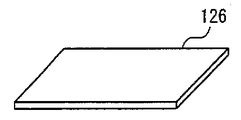
図5は、銅圧延素材の金属平板126の外観を示す図である。銅圧延素材の金属平板126の表面には、酸化銅の絶縁被覆の表面処理がされている。プレス工程において、銅圧延素材の金属平板126は、コの字形状にプレス成形される。そして、コの字形状にプレス成形された金属平板は、図4において説明したように、予め定められた枚数だけ積層される。そして、金属平板を積層カシメにより互いに固定することにより、図6(A)に示すように、積層体コイル114が形成される。そして、積層体コイル114は、図6(B)に示すように、隣接する積層体コイルに対する絶縁処理が行なわれる。隣接する積層体コイルとの絶縁は、特に限定されるものではないが、たとえば、ガラス等の無機材質を介在させてもよいし、積層体毎にエナメル処理を施してもよい。そして、積層体コイル114は、図6(C)に示すように、絶縁体上の所定の位置に接着剤を塗布して、他の積層体コイルと接着することができる。あるいは、図4(D)を用いて説明したように積層体コイルの互いの突出部の凹部を接着剤の受け皿として用いてもよい。
FIG. 5 is a view showing an appearance of a metal
絶縁体を介在させて複数の積層体コイルを接着することにより、図7に示すようにコイル112が形成される。このとき、コイル112を形成する積層体コイルのそれぞれにおいて異なる寸法を有するコの字形状の金属平板を積層する。このようにして、スロットに挿入される積層体コイルの断面形状を自由に設定することができる。すなわち、スロットの形状に合わせて、同期モータの径方向の内周側から外周側にかけて、(図7において、上部から底部にかけて)、コの字形状のスロットに挿入される金属平板の幅を大きくする。そのため、スロット内におけるコイル112の占積率を高くすることができる。
By bonding a plurality of laminated coils with an insulator interposed, a
複数の積層体コイルにより形成されたコイル112は、図8に示すように、ステータコア102のティース108を跨ぐようにして挿入される。すなわち、コイル112の上底および下底に対応するそれぞれの開放端部は、同期モータの回転軸方向と平行な方向に、ティース108の両脇のスロット146、148に対してそれぞれ挿入される。
As shown in FIG. 8, the
積層体コイルの開放端部とバスバーとが接触する接触部において、予め定められた枚数の金属平板のうちの一部に板厚方向と直交する長さを異なる長さとして所定形状の切り欠きを設けることにより、嵌合部が形成される。嵌合部を形成することにより、バスバーの組付け性が向上する。 At the contact portion where the open end of the laminated coil and the bus bar are in contact with each other, a predetermined number of notches having different lengths perpendicular to the plate thickness direction are formed in a part of a predetermined number of metal flat plates. By providing, a fitting part is formed. By forming the fitting portion, the assemblability of the bus bar is improved.
図9に、スロット146および148に挿入されたコイル112の開放端部を示す。図9に示すように、コイル112を形成する積層体コイルは、積層体コイルの各々において異なる形状の嵌合部を有する。また、各積層体コイルの各々において、異なる形状の嵌合部を有することにより、バスバーが組み付けられる際に、組み付け間違いを防止することができる。異なる嵌合部の形状は、積層体コイルを形成する金属平板において、所定形状の切り欠きを有する金属平板の枚数を変更することにより実現できる。
FIG. 9 shows the open end of
なお、図10に示すように、各積層体コイルの接合部に対応した複数のバスバーを個別に組み付ける場合、少なくとも隣接する積層体コイルにおける嵌合部の形状と異なることとする。隣接する積層体コイルの嵌合部の形状が異なることにより、バスバーの組み付け間違いを防止することができる。 In addition, as shown in FIG. 10, when the several bus bar corresponding to the junction part of each laminated body coil is assembled | attached separately, it shall differ from the shape of the fitting part in an adjacent laminated body coil at least. Since the shapes of the fitting portions of the adjacent laminated coils are different, it is possible to prevent an assembly error of the bus bar.
特に、図11に示すように、複数のバスバーが固定された位置決めブロック104により一度に組み付け等の作業を行なう場合は、コイル112における各積層体コイルの開放端部の嵌合部において少なくとも1つが異なる形状を有することにより、バスバーの組み付け時の組み付け間違いを防止することができる。さらに、接合場所が特定されるために、位置決めを行なうための治具なしで接合処理を施すことができる。本実施の形態においては、内周側の3つの積層体コイルと、中央の3つの積層体コイルと、外周側の4つの積層体コイルとで嵌合部は、異なる形状を有する。
In particular, as shown in FIG. 11, when an assembly operation or the like is performed at once by the
バスバーが積層体コイルに組み付けられると、図12に示すように、コイル112に組み付けられたバスバーと各積層体コイルの開放端部とのそれぞれの嵌合部は、一点毎にレーザ溶接、あるいは、TIG溶接により多点接合される。
When the bus bar is assembled to the laminate coil, as shown in FIG. 12, each fitting portion of the bus bar assembled to the
バスバーと各積層体コイルの開放端部とが接合されると、渡り部材を用いてティース毎に巻着されたコイルが接続される。すなわち、本実施の形態の同期モータは、三相の交流同期モータであるため、3ティース毎にコイルの外周側のコイル端部と内周側のコイル端部とが図13に示すように、渡り部材を用いて接続される。そして、図14に示すように、コイル112と渡り部材106とをレーザ溶接あるいはTIG溶接により、接合処理が施される。その結果、図1に示すような固定子100が形成される。そして、コイルエンド部に対して樹脂等を用いてモールド処理が施されて、図15に示すような固定子100が形成される。
When the bus bar and the open end of each laminated body coil are joined, the coil wound for each tooth is connected using the transition member. That is, since the synchronous motor of the present embodiment is a three-phase AC synchronous motor, the coil end on the outer peripheral side of the coil and the coil end on the inner peripheral side are shown in FIG. They are connected using a transition member. Then, as shown in FIG. 14, the
本実施の形態に係る同期モータの固定子の製造方法においては、従来、コイルが巻着される前に行なっていた絶縁処理をコイルが巻着された後に行なう。このようにして、コイルおよび固定子鉄心に付着された絶縁材料の傷つきを防止するものである。 In the method for manufacturing the stator of the synchronous motor according to the present embodiment, the insulation treatment that has been conventionally performed before the coil is wound is performed after the coil is wound. In this way, the insulating material attached to the coil and the stator core is prevented from being damaged.
本実施の形態に係る同期モータの固定子の製造方法は、図16に示すような手順で行なわれる。 The method for manufacturing the stator of the synchronous motor according to the present embodiment is performed according to the procedure shown in FIG.
すなわち、S1000にて、固定子鉄心が製造される。すなわち、固定子鉄心は、電磁鋼板を所定の形状にプレス成形した後、予め定められた枚数だけ積層して形成される。S1100にて、コイルは、固定子鉄心のティースの形状に合致する形状に成形される。ここで、「ティースの形状に合致する形状」とは、コイルがティースに巻着されたときに、コイルとティースとの間で隙間が生じるように設計された形状である。本実施の形態に係るコイルは、図2に示したようにコの字形状の金属平板を積層した積層体コイルである。積層体コイルを固定子鉄心のティースを跨ぐようにして組み付けたときに、コの字形状の積層体コイルにおける開放端部を有する二つの部材間の幅の寸法は、対応するティースの幅の寸法よりも大きい寸法になるように設計される。 That is, a stator core is manufactured in S1000. That is, the stator iron core is formed by pressing a predetermined number of magnetic steel sheets after they are press-formed into a predetermined shape. At S1100, the coil is formed into a shape that matches the shape of the teeth of the stator core. Here, the “shape that matches the shape of the teeth” is a shape designed so that a gap is generated between the coil and the teeth when the coil is wound around the teeth. The coil according to the present embodiment is a laminated coil in which U-shaped metal flat plates are laminated as shown in FIG. When the laminated body coil is assembled so as to straddle the teeth of the stator core, the width dimension between the two members having the open ends in the U-shaped laminated body coil is the width dimension of the corresponding tooth. It is designed to have a larger dimension.
S1200にて、固定子鉄心に対して成形されたコイルを組み付ける。すなわち、図8〜図12までに示したように、固定子鉄心が有するスロットに対してコイルの開放端部を挿入する。このとき、コイルはスロット間のティースに跨ぐようにして組み付けられる。そして、コイルの開放端部に対してバスバーを用いて接続することにより、固定子鉄心に対してコイルが巻着された状態とする。このとき、コイルと固定子鉄心との間には、積層体コイルの二つの部材間の幅の寸法とティース幅の寸法との差に応じて隙間が生じる。 At S1200, the coil formed on the stator core is assembled. That is, as shown in FIGS. 8 to 12, the open end of the coil is inserted into the slot of the stator core. At this time, the coil is assembled so as to straddle the teeth between the slots. And it is set as the state by which the coil was wound with respect to the stator core by connecting to the open end part of a coil using a bus bar. At this time, a gap is generated between the coil and the stator core according to the difference between the width dimension between the two members of the multilayer coil and the tooth width dimension.
S1300にて、結線処理が行なわれる。すなわち、各スロットに巻着されたコイルの端部は、それぞれ対応するコイルの端部と、図13および図14に示したように渡り部材により結線処理が行なわれる。S1400にて、後絶縁工程が行なわれる。後絶縁工程とは、本実施の形態に係る回転電機においては、図15に示したように、固定子鉄心に巻着されたコイルに対して絶縁処理を施す処理である。絶縁処理については、本実施の形態において樹脂を加圧してコイルに付着されるいわゆる射出成形による絶縁処理を施すが、特に限定されるものではない。たとえば、エナメル材等の絶縁材料を満たした容器にコイルが巻着された固定子鉄心を含浸させることにより、コイルに対して絶縁処理を施してもよい。あるいは、容器にコイルが巻着された固定子鉄心を入れて密閉し、内部の空気を抜いた真空雰囲気において絶縁材料を充填していく真空含浸により絶縁処理を施してもよい。 In S1300, connection processing is performed. In other words, the ends of the coils wound around the slots are connected to the corresponding ends of the coils by the crossover members as shown in FIGS. 13 and 14. In S1400, a post-insulation process is performed. The post-insulation process is a process of performing an insulation process on the coil wound around the stator core as shown in FIG. 15 in the rotating electrical machine according to the present embodiment. The insulation treatment is not particularly limited, although the insulation treatment is performed by so-called injection molding in which the resin is pressurized and attached to the coil in the present embodiment. For example, the coil may be insulated by impregnating a stator core with the coil wound around a container filled with an insulating material such as an enamel material. Alternatively, the insulation may be performed by vacuum impregnation in which a stator iron core around which a coil is wound is put in a container and hermetically sealed, and an insulating material is filled in a vacuum atmosphere in which the air is removed.
このようにして、後絶縁工程における絶縁処理は、固定子鉄心とコイルとの隙間を絶縁材料である樹脂を用いて埋めるようにして絶縁される。そして、絶縁処理は、コイルと隣接するティースに巻着されるコイルとの間の隙間を樹脂を用いて埋めるようにして絶縁する。さらには、絶縁処理は、渡り部材あるいはバスバーとが接続されるコイルの結線処理処理部を樹脂を用いて埋めるようにして絶縁する。すなわち、本実施の形態においては、コイルが固定子鉄心に巻着された後に固定子鉄心とコイルとの間、コイルと隣接するティースに巻着されたコイルとの間、コイルの結線処理部の3ヶ所を同時に絶縁処理を行なう。絶縁処理が固定子鉄心にコイルが巻着された後に行なわれることにより、製造工程における絶縁被覆への傷つきを回避することができる。S1500にて、製造された固定子の不良品の検査等の最終検査を行なう。 In this way, the insulation process in the post-insulation process is insulated by filling the gap between the stator core and the coil with the resin that is an insulating material. In the insulation treatment, insulation is performed by filling a gap between the coil and the coil wound around the adjacent tooth with resin. Furthermore, the insulation process is performed by filling the wire connection processing part of the coil to which the crossover member or the bus bar is connected with resin. That is, in the present embodiment, after the coil is wound around the stator core, between the stator core and the coil, between the coil wound around the teeth adjacent to the coil, the coil connection processing unit Insulate 3 places at the same time. By performing the insulation treatment after the coil is wound around the stator core, it is possible to avoid damage to the insulation coating in the manufacturing process. In S1500, final inspection such as inspection of defective products of the manufactured stator is performed.
以上のようにして、本実施の形態に係る回転電機の固定子の製造方法によると、コイルを形成するステップにて、コイルは、固定子鉄心が有するティースとコイルとの間に隙間を有するように設計された形状に形成される。コイルをティースに巻着させるステップにて、コイルは、ティースに巻着される。処理ステップにて、固定子鉄心に巻着されたコイルに対して絶縁処理を施す。このように、固定子鉄心にコイルが巻着された後に、固定子鉄心のティースとコイルとの間の隙間に対して絶縁処理を行なうことにより、品質の高い絶縁処理を施すことができる。すなわち、コイルの巻着後に絶縁処理を施すため、固定子鉄心へのコイル組み付け時に固定子鉄心あるいは、コイルは、絶縁被覆されていない。そのため、コイルの組み付け時に絶縁被覆が傷つくことを回避することができる。したがって、絶縁処理は、高い絶縁品質を確保することができる。これにより、絶縁品質を向上させた回転電機の固定子の製造方法を提供することができる。 As described above, according to the method for manufacturing a stator for a rotating electrical machine according to the present embodiment, in the step of forming the coil, the coil has a gap between the teeth of the stator core and the coil. It is formed in the shape designed in the above. In the step of winding the coil around the teeth, the coil is wound around the teeth. In the processing step, an insulation process is performed on the coil wound around the stator core. As described above, after the coil is wound around the stator core, the insulation process is performed on the gap between the teeth of the stator core and the coil, whereby a high-quality insulation process can be performed. That is, since the insulation treatment is performed after the coil is wound, the stator core or the coil is not covered with the insulation when the coil is assembled to the stator core. Therefore, it is possible to avoid damage to the insulating coating during assembly of the coil. Therefore, the insulation process can ensure high insulation quality. Thereby, the manufacturing method of the stator of the rotary electric machine which improved insulation quality can be provided.
また、固定子鉄心へのコイルの組み付け時においては、絶縁被覆されていないため、部品の精度が高い。そして、コイルの組み付け時に絶縁被覆の傷つきを考慮する必要がない。そのため、固定子鉄心へのコイルの組み付けの工程を自動化することができる。すなわち、固定子鉄心へのコイルの組み付け性が向上する。そして、組み付けたコイルの品質の安定が図れる。さらに、絶縁被覆の傷つきが起こらないため、固定子の中間検査として行なわれる絶縁検査の工程を省略することができる。そのため、固定子の製造時間の短縮が図れる。すなわち、固定子の製造コストの低減が図れる。 In addition, when the coil is assembled to the stator core, since the insulation coating is not provided, the accuracy of the parts is high. And it is not necessary to consider the damage of an insulation coating at the time of the assembly | attachment of a coil. Therefore, the process of assembling the coil to the stator core can be automated. That is, the assembling property of the coil to the stator core is improved. In addition, the quality of the assembled coil can be stabilized. Furthermore, since the insulation coating is not damaged, an insulation inspection process performed as an intermediate inspection of the stator can be omitted. Therefore, the manufacturing time of the stator can be shortened. That is, the manufacturing cost of the stator can be reduced.
そして、上述したように固定子の絶縁被覆に対して製造工程におけるダメージを受けることがなくなるため、製造工程におけるダメージに対する絶縁材料の強度を確保する必要がなくなる。そのため、耐熱性、耐電圧のより高い絶縁材料を使用することができる。すなわち、回転電機の耐熱性、耐電圧を向上させることができる。 As described above, since the stator insulation coating is not damaged in the manufacturing process, it is not necessary to ensure the strength of the insulating material against the damage in the manufacturing process. Therefore, an insulating material with higher heat resistance and withstand voltage can be used. That is, the heat resistance and voltage resistance of the rotating electrical machine can be improved.
さらに、製造工程におけるダメージに対する絶縁品質、信頼性を確保する必要がなくなるために絶縁材料の選択が制限されることもなくなる。したがって、今まで製造工程におけるダメージに対する強度等が確保できないため使用できなかった無機系の材料(たとえば、セラミックス、ガラス繊維等)を絶縁材料として使用することができる。 Furthermore, since it is not necessary to ensure insulation quality and reliability against damage in the manufacturing process, selection of the insulation material is not restricted. Therefore, an inorganic material (for example, ceramics, glass fiber, etc.) that could not be used because the strength against damage in the manufacturing process cannot be ensured until now can be used as the insulating material.
また、コイルが固定子鉄心に巻着された後にコイルと固定子鉄心との間が絶縁されるように処理される。コイルの巻着後に絶縁処理を施すため、固定子鉄心へのコイルの組み付け時には、固定子鉄心あるいはコイルは絶縁被覆されていない。また、コイルは、固定子鉄心のティースとコイルとの間に隙間を有するように設計された形状に形成される。そのため、コイルの組み付け時に、絶縁被覆が傷つくことを回避することができる。したがって、コイルと固定子鉄心との間の、コイルの寸法とティースの寸法の差に応じて生じる隙間に対して絶縁処理により、高い絶縁品質を確保することができる。 Further, after the coil is wound around the stator core, the coil and the stator core are processed so as to be insulated. Since the insulation treatment is performed after the coil is wound, the stator core or coil is not covered with insulation when the coil is assembled to the stator core. The coil is formed in a shape designed to have a gap between the teeth of the stator core and the coil. Therefore, it is possible to avoid damage to the insulating coating when the coil is assembled. Therefore, high insulation quality can be ensured by insulation treatment for the gap generated according to the difference between the coil dimension and the tooth dimension between the coil and the stator core.
そして、コイルが固定子鉄心に巻着された後にコイルと、コイルが巻着されたティースと隣接するティースに巻着されたコイルとの間が絶縁されるように処理される。コイルの巻着後に絶縁処理を施すため、固定子鉄心へのコイル組み付け時に固定子鉄心あるいは、コイルは、絶縁被覆されていない。そのため、コイルの組み付け時に絶縁被覆が傷つくことを回避することができる。したがって、コイルと、コイルが巻着されたティースと隣接するティースに巻着されたコイルとの間に対しての絶縁処理により、高い絶縁品質を確保することができる。 Then, after the coil is wound around the stator core, the coil is treated so as to be insulated between the coil wound around the coil and the tooth wound around the adjacent tooth. Since the insulation treatment is performed after the coil is wound, the stator core or the coil is not covered with insulation when the coil is assembled to the stator core. Therefore, it is possible to avoid damage to the insulating coating during assembly of the coil. Therefore, high insulation quality can be ensured by the insulation treatment between the coil and the coil wound around the adjacent tooth and the tooth around which the coil is wound.
さらに、コイルが固定子鉄心に巻着された後に結線処理されたコイルが絶縁されるように処理される。コイルの巻着後に絶縁処理を施すため、固定子鉄心へのコイル組み付け時に固定子鉄心あるいは、コイルは、絶縁被覆されていない。そのため、コイルの組み付け時に絶縁被覆が傷つくことを回避することができる。したがって、結線処理されたコイルに対しての絶縁処理により、高い絶縁品質を確保することができる。 Furthermore, after the coil is wound around the stator core, the coil that has been connected is processed so as to be insulated. Since the insulation treatment is performed after the coil is wound, the stator core or the coil is not covered with insulation when the coil is assembled to the stator core. Therefore, it is possible to avoid damage to the insulating coating during assembly of the coil. Therefore, high insulation quality can be ensured by the insulation treatment for the coil subjected to the wire connection treatment.
そして、コイルが固定子鉄心に巻着された後に絶縁処理を施すため、固定子鉄心とコイルとの間、コイルと、コイルが巻着されたティースと隣接するティースに巻着されたコイルとの間、結線処理されたコイルの結線処理部の3ヶ所の中の少なくとも2ヶ所が同時に絶縁されるように処理することが可能になる。そのため、製造時間の短縮が図れる。したがって、固定子の製造コストの低減が図れる。 And in order to insulate after the coil is wound around the stator core, between the stator core and the coil, the coil, and the coil wound around the tooth around which the coil is wound In the meantime, it is possible to perform processing so that at least two of the three connection processing portions of the connected coil are insulated at the same time. Therefore, the manufacturing time can be shortened. Therefore, the manufacturing cost of the stator can be reduced.
なお、本実施の形態において、積層体コイル間の絶縁は、積層体コイル間に絶縁材料を介在させることにより行なわれるがたとえば、積層体コイルを固定子鉄心に挿入する際に積層体コイル間で隙間が生じるように組み付けてもよい。すなわち、後絶縁工程において、固定子鉄心とコイルとの間、積層体コイル間、コイルと、コイルが巻着されたティースと隣接するティースに巻着されたコイルとの間、結線処理されたコイルの結線処理部の4ヶ所の中の少なくとも2ヶ所が同時に絶縁されるように処理することが可能になる。 In this embodiment, the insulation between the laminate coils is performed by interposing an insulating material between the laminate coils. For example, when the laminate coils are inserted into the stator core, You may assemble | attach so that a clearance gap may arise. That is, in the post-insulation process, a coil that is connected between the stator iron core and the coil, between the laminated body coils, between the coil and the coil wound around the tooth around which the coil is wound. Thus, it is possible to perform processing so that at least two of the four connection processing sections are simultaneously insulated.
また、コイルをスロットに挿入する前に絶縁処理を行なった場合においても、コイル挿入後に上述したような箇所に絶縁処理を行なえばよい。 Even when the insulation process is performed before the coil is inserted into the slot, the insulation process may be performed at the above-described locations after the coil is inserted.
<第2の実施の形態>
以下、第2の実施の形態に係る回転電機の固定子の製造方法について説明する。本実施の形態に係る固定子の製造方法を説明するにあたり、まず、この固定子の製造方法により製造された回転電機の固定子の構造について同期モータの固定子を一例として説明する。
<Second Embodiment>
Hereinafter, a method for manufacturing the stator of the rotating electrical machine according to the second embodiment will be described. In describing the stator manufacturing method according to the present embodiment, first, the structure of the stator of the rotating electrical machine manufactured by the stator manufacturing method will be described by taking the stator of the synchronous motor as an example.
図17に示すように、本実施の形態に係る同期モータの固定子200は、部分固定子鉄心202と、コイル端部204、206と、渡り部材208と、端子210とから構成される。部分固定子鉄心は、複数が組み合わされて、同期モータの固定子鉄心を形成する。
As shown in FIG. 17, the
部分固定子鉄心202にコイル(図示せず)が巻着されている。そして、巻着されたコイルのコイル端部206が渡り部材208を介して部分固定子鉄心218のコイル端部と接続される。そして、端子210と他の2つの端子(図示せず)とのそれぞれに交流電力の位相を制御して供給する。これにより、固定子200には、磁界が発生する。
A coil (not shown) is wound around the
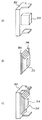
図18(A)に示すように、固定子鉄心の製造工程において、部分固定子鉄心202が製造される。部分固定子鉄心202の製造方法は、特に限定されるものではないが、たとえば、粗形材を加工することにより形成されてもよいし、鉄粉に絶縁樹脂を混合し圧縮成形した、いわゆる圧粉成形により形成されてもよい。
As shown in FIG. 18A, a
一方、図18(B)に示すようにコイル端部204、206を有するコイル212が巻回される。このコイル212を形成する導電部材は、絶縁処理が施されていない。このコイル212の導電部材の製造方法は、特に限定されるものではないが、たとえば、本実施の形態において、コイル212は、直線形状の金属平板を導電部材として、この金属平板を屈曲させてらせん形状に形成して製造される。このとき、コイル212は、らせん形状に形成される金属平板同士が接触する接触部において、隙間が生じるように設計される形状である。さらに、コイル212は、ティース214の形状に合致する形状になるように形成される。すなわち、コイル212をティース214に挿入したときに、コイル212とティース214との間に隙間が生じる形状になるように設計される。具体的には、コイル212のらせん形状の金属平板における内側の穴の幅、高さの寸法がティース212の幅、高さの寸法よりも大きい寸法になるように設計される。
On the other hand, a
そして、図18(C)に示すように、コイル212は、部分固定子鉄心202に設けられるティース214に挿入されて巻着された状態となる。このとき、コイル212とティース214との間には、上述したようなそれぞれの寸法の差に応じて隙間が生じる。
Then, as shown in FIG. 18C, the
そして、コイル212が巻着された部分固定子鉄心202は、図19に示すように、同様に形成される部分固定子鉄心216と接続される。部分固定子鉄心同士の接続は、特に限定されるものではないが、たとえば、部分固定子鉄心202におけるヨーク部の周方向の両端部に凹凸形状の突出部および開口部をそれぞれ設ける。そして、隣接する部分固定子鉄心216が有する凹凸形状の突出部および開口部と嵌合することにより、接続される。
Then, as shown in FIG. 19, the
以上のようにして、固定子鉄心が構成される。そして、各部分固定子鉄心に対応するコイル端部がそれぞれ3つごとに渡り部材を介して接続される結線処理が施されることにより、図17に示すような三相交流同期モータの固定子を構成する。 The stator core is configured as described above. Then, by performing a connection process in which the coil ends corresponding to the partial stator cores are connected via three crossing members, the stator of the three-phase AC synchronous motor as shown in FIG. Configure.
以上のような製造工程を経て構成された固定子200に対して、絶縁材料である樹脂を用いて絶縁処理を施す。すなわち、絶縁処理は、部分固定子鉄心202に巻着されたコイル212を形成するらせん形状の金属平板同士間に形成された隙間を樹脂で埋めるようにして絶縁する。そして、絶縁処理は、コイル212と部分固定子鉄心202との間に生じる隙間を樹脂を用いて埋めるようにして絶縁する。さらに、絶縁処理は、コイル212と、部分固定子鉄心202に隣接する部分固定子鉄心に巻着されるコイルとの隙間を樹脂を用いて埋めるようにして絶縁する。そして、絶縁処理は、コイル端部と渡り部材が接続される結線処理部が樹脂を用いて埋めるようにして絶縁する。
The
絶縁処理については、本実施の形態において樹脂を加圧してコイルに付着されるいわゆる射出成形による絶縁処理を施すが、特に限定されるものではない。たとえば、エナメル材等の絶縁材料に満たした容器にコイルが巻着された固定子鉄心を含浸させることにより、コイルに対して絶縁処理を施しても良い。あるいは、容器にコイルが巻着された固定子鉄心を入れて密閉し、内部の空気を抜いた真空雰囲気において絶縁材料を充填していく真空含浸により絶縁処理を施しても良い。 The insulation treatment is not particularly limited, although the insulation treatment is performed by so-called injection molding in which the resin is pressurized and attached to the coil in the present embodiment. For example, the coil may be insulated by impregnating a stator core with the coil wound around a container filled with an insulating material such as enamel. Alternatively, the insulation may be performed by vacuum impregnation in which a stator core having a coil wound around a container is sealed and sealed, and an insulating material is filled in a vacuum atmosphere in which the air is removed.
本実施の形態においては、コイルが固定子鉄心に巻着された後に、固定子鉄心とコイルとの間、らせん形状に形成された金属平板同士の接触部、コイルと隣接するティースに巻着されたコイルとの間、コイルの結線処理部の4ヶ所を同時に絶縁処理を行なう。絶縁処理が固定子鉄心にコイルが巻着された後に行なわれることにより、製造工程における絶縁被覆への傷つきを回避することができる。 In the present embodiment, after the coil is wound around the stator core, the coil is wound between the stator core and the coil, the contact portion between the metal flat plates formed in a spiral shape, and the tooth adjacent to the coil. Insulation treatment is simultaneously performed at four locations in the coil connection processing section between the coil and the other coil. By performing the insulation treatment after the coil is wound around the stator core, it is possible to avoid damage to the insulation coating in the manufacturing process.
このような構成の回転電機の固定子200の製造方法は、前述した第1の実施の形態において、S2400の後絶縁工程において、コイルを形成する金属平板同士の接触部に対して絶縁処理をさらに含む以外、図16を用いて説明した手順と同様の手順で行なわれる。そのため、詳細な説明は繰り返さない。
In the manufacturing method of the
以上のようにして、本実施の形態に係る回転電機の固定子の製造方法によると、前述の第1の実施の形態と同様の効果を有する。 As described above, the method for manufacturing a stator for a rotating electrical machine according to the present embodiment has the same effects as those of the first embodiment described above.
さらに、固定子鉄心における各ティースに巻着されたコイルは、らせん形状に形成された金属平板で形成される。また、コイルは、金属平板同士が接触する接触部を有する。なお、「接触部」は、金属平板同士の間に隙間を有している状態を含む。そして、処理ステップにて、コイルが固定子鉄心に巻着された後に接触部が絶縁されるように処理される。コイルの巻着後に接触部の絶縁処理を施すため、固定子鉄心へのコイル組み付け時に固定子鉄心あるいは、コイルは、絶縁被覆されていない。そのため、コイルの組み付け時に絶縁被覆が傷つくことを回避することができる。したがって、接触部に対しての絶縁処理により、高い絶縁品質を確保することができる。 Furthermore, the coil wound around each tooth in the stator core is formed of a metal flat plate formed in a spiral shape. Moreover, a coil has a contact part which metal flat plates contact. The “contact portion” includes a state where there is a gap between the metal flat plates. And in a process step, after a coil is wound around a stator core, it processes so that a contact part may be insulated. In order to insulate the contact portion after the coil is wound, the stator core or the coil is not covered with insulation when the coil is assembled to the stator core. Therefore, it is possible to avoid damage to the insulating coating during assembly of the coil. Therefore, high insulation quality can be ensured by the insulation treatment for the contact portion.
また、コイルが固定子鉄心に巻着された後に絶縁処理を施すため、固定子鉄心とコイルとの間、コイルの金属平板同士の接触部、コイルと、コイルが巻着されたティースと隣接するティースに巻着されたコイルとの間、結線処理されたコイルの結線処理部の4ヶ所の中の少なくとも2ヶ所が同時に絶縁されるように処理することが可能になる。そのため、製造時間の短縮が図れる。したがって、固定子の製造コストの低減が図れる。 Moreover, in order to perform insulation treatment after the coil is wound around the stator core, the contact portion between the metal flat plates of the coil, the coil, and the tooth around which the coil is wound are adjacent to each other between the stator core and the coil. It is possible to perform processing so that at least two of the four connection processing portions of the coil that has been connected to the coil wound around the teeth are insulated at the same time. Therefore, the manufacturing time can be shortened. Therefore, the manufacturing cost of the stator can be reduced.
今回開示された実施の形態はすべての点で例示であって制限的なものではないと考えられるべきである。本発明の範囲は上記した説明ではなくて特許請求の範囲によって示され、特許請求の範囲と均等の意味および範囲内でのすべての変更が含まれることが意図される。 The embodiment disclosed this time should be considered as illustrative in all points and not restrictive. The scope of the present invention is defined by the terms of the claims, rather than the description above, and is intended to include any modifications within the scope and meaning equivalent to the terms of the claims.
100,200 固定子、102 ステータコア、104 バスバー位置決めブロック、106,208 渡り部材、108,214 ティース、110 バスバー、112,212 コイル、114,124 積層体コイル、116,120,122,126 金属平板、134,136,138,140,142,144,204,206 コイル端部、146,148 スロット、150,152,218,318 端部、202,216,218 部分固定子鉄心、210 端子。 100, 200 Stator, 102 Stator core, 104 Bus bar positioning block, 106, 208 Transition member, 108, 214 Teeth, 110 Bus bar, 112, 212 coil, 114, 124 Laminate coil, 116, 120, 122, 126 Metal flat plate, 134, 136, 138, 140, 142, 144, 204, 206 Coil end, 146, 148 slot, 150, 152, 218, 318 end, 202, 216, 218 Partial stator core, 210 terminals.
Claims (4)
前記固定子の製造方法は、前記固定子鉄心を製造するとともに、前記コイルを、前記ティースに巻着されたときに前記ティースとの間に隙間が生じるように設計された形状に形成し、次に前記コイルを前記ティースに巻着し、そして前記固定子鉄心に巻着された前記コイルに対して絶縁処理するものであり、
前記絶縁処理では、前記固定子鉄心と前記コイルとの間、前記コイルと、前記コイルが巻着された前記ティースと隣接するティースに巻着されたコイルとの間、および、結線処理された前記コイルの結線処理部のいずれも未だ絶縁処理されていない3ヶ所を同時に絶縁材料で埋めるようにして絶縁する、
固定子の製造方法。 A method of manufacturing a stator of a rotating electrical machine comprising a rotor and a stator, wherein the stator is a coil comprising a stator core having a plurality of teeth and a metal flat plate wound around the teeth. A coil end portion having a cross-sectional area larger than a cross-sectional area of a portion arranged in a slot between teeth of the stator core,
The method for manufacturing the stator includes manufacturing the stator iron core, and forming the coil in a shape designed so that a gap is formed between the coil and the teeth when wound. The coil is wound around the teeth, and the coil wound around the stator core is insulated.
In the insulation process, between the stator core and the coil, between the coil and a coil wound around a tooth adjacent to the tooth around which the coil is wound, and the wire connection process Insulate so that all of the coil connection processing parts are not filled with insulation at the same time by filling them with insulating material at the same time.
Stator manufacturing method.
Priority Applications (1)
| Application Number | Priority Date | Filing Date | Title |
|---|---|---|---|
| JP2003411276A JP4624663B2 (en) | 2003-12-10 | 2003-12-10 | Stator manufacturing method |
Applications Claiming Priority (1)
| Application Number | Priority Date | Filing Date | Title |
|---|---|---|---|
| JP2003411276A JP4624663B2 (en) | 2003-12-10 | 2003-12-10 | Stator manufacturing method |
Related Child Applications (1)
| Application Number | Title | Priority Date | Filing Date |
|---|---|---|---|
| JP2009299115A Division JP5035334B2 (en) | 2009-12-29 | 2009-12-29 | Stator manufacturing method |
Publications (2)
| Publication Number | Publication Date |
|---|---|
| JP2005176470A JP2005176470A (en) | 2005-06-30 |
| JP4624663B2 true JP4624663B2 (en) | 2011-02-02 |
Family
ID=34732064
Family Applications (1)
| Application Number | Title | Priority Date | Filing Date |
|---|---|---|---|
| JP2003411276A Expired - Fee Related JP4624663B2 (en) | 2003-12-10 | 2003-12-10 | Stator manufacturing method |
Country Status (1)
| Country | Link |
|---|---|
| JP (1) | JP4624663B2 (en) |
Families Citing this family (3)
| Publication number | Priority date | Publication date | Assignee | Title |
|---|---|---|---|---|
| JP5691266B2 (en) * | 2010-07-01 | 2015-04-01 | トヨタ自動車株式会社 | Rotating electric machine stator |
| JP5269270B2 (en) * | 2011-03-30 | 2013-08-21 | 三菱電機株式会社 | Electric motor and method of manufacturing electric motor |
| CN110518757B (en) * | 2019-09-23 | 2024-03-26 | 巨力自动化设备(浙江)有限公司 | Motor stator hairpin type conducting strip flaring layering shaping device |
-
2003
- 2003-12-10 JP JP2003411276A patent/JP4624663B2/en not_active Expired - Fee Related
Also Published As
| Publication number | Publication date |
|---|---|
| JP2005176470A (en) | 2005-06-30 |
Similar Documents
| Publication | Publication Date | Title |
|---|---|---|
| JP4797728B2 (en) | Stator for rotating electrical machine, parts used for stator and method for manufacturing stator for rotating electrical machine | |
| JP2005160143A (en) | Stator for dynamo-electric machine | |
| US6140734A (en) | Armature with regular windings and having a high conductor density | |
| JP5282527B2 (en) | Motor coil wiring components | |
| JP5083329B2 (en) | Stator and rotating electric machine using the same | |
| CN112368912B (en) | Radial gap type rotary motor with distributed winding method and stator thereof | |
| JP2007267463A (en) | Rotating electric machine and manufacturing method for rotary electric machine | |
| JP2010110144A (en) | Wiring component for motor coil | |
| US5793138A (en) | Fabrication of induction motors | |
| JP4631340B2 (en) | Rotating electric machine | |
| JP4665454B2 (en) | motor | |
| WO2014041637A1 (en) | Armature of rotating electrical machine and method for manufacturing same | |
| JP2007295698A (en) | Stator of rotary electric machine | |
| JP2008104288A (en) | Capacitor motor, and manufacturing method therefor | |
| JP2005137174A (en) | Process for manufacturing stator and stator of rotary electric machine manufactured through that process | |
| JP4241321B2 (en) | Rotating electric machine stator | |
| JP5035334B2 (en) | Stator manufacturing method | |
| CN113939979B (en) | Coil, stator, rotor, motor having the coil, and method for manufacturing the coil | |
| JP4624663B2 (en) | Stator manufacturing method | |
| CN110504777B (en) | Armature of motor | |
| JP2004040871A (en) | Stator core and motor | |
| EP3477819B1 (en) | Method for producing a stator, and teeth stack for a stator | |
| JPH07135745A (en) | Core of motor | |
| JP6710180B2 (en) | motor | |
| JPH07111747A (en) | Stator for motor |
Legal Events
| Date | Code | Title | Description |
|---|---|---|---|
| RD04 | Notification of resignation of power of attorney |
Free format text: JAPANESE INTERMEDIATE CODE: A7424 Effective date: 20050425 |
|
| RD03 | Notification of appointment of power of attorney |
Free format text: JAPANESE INTERMEDIATE CODE: A7423 Effective date: 20050426 |
|
| A521 | Written amendment |
Free format text: JAPANESE INTERMEDIATE CODE: A821 Effective date: 20050427 |
|
| RD04 | Notification of resignation of power of attorney |
Free format text: JAPANESE INTERMEDIATE CODE: A7424 Effective date: 20050427 |
|
| A621 | Written request for application examination |
Free format text: JAPANESE INTERMEDIATE CODE: A621 Effective date: 20060927 |
|
| A977 | Report on retrieval |
Free format text: JAPANESE INTERMEDIATE CODE: A971007 Effective date: 20090203 |
|
| A131 | Notification of reasons for refusal |
Free format text: JAPANESE INTERMEDIATE CODE: A131 Effective date: 20090210 |
|
| A521 | Written amendment |
Free format text: JAPANESE INTERMEDIATE CODE: A523 Effective date: 20090407 |
|
| A02 | Decision of refusal |
Free format text: JAPANESE INTERMEDIATE CODE: A02 Effective date: 20090929 |
|
| A521 | Written amendment |
Free format text: JAPANESE INTERMEDIATE CODE: A523 Effective date: 20091229 |
|
| A911 | Transfer of reconsideration by examiner before appeal (zenchi) |
Free format text: JAPANESE INTERMEDIATE CODE: A911 Effective date: 20100107 |
|
| A912 | Removal of reconsideration by examiner before appeal (zenchi) |
Free format text: JAPANESE INTERMEDIATE CODE: A912 Effective date: 20100312 |
|
| A521 | Written amendment |
Free format text: JAPANESE INTERMEDIATE CODE: A523 Effective date: 20100927 |
|
| A01 | Written decision to grant a patent or to grant a registration (utility model) |
Free format text: JAPANESE INTERMEDIATE CODE: A01 |
|
| A61 | First payment of annual fees (during grant procedure) |
Free format text: JAPANESE INTERMEDIATE CODE: A61 Effective date: 20101104 |
|
| FPAY | Renewal fee payment (event date is renewal date of database) |
Free format text: PAYMENT UNTIL: 20131112 Year of fee payment: 3 |
|
| LAPS | Cancellation because of no payment of annual fees |