JP4621168B2 - Ribbon cassette and printer - Google Patents
Ribbon cassette and printer Download PDFInfo
- Publication number
- JP4621168B2 JP4621168B2 JP2006143152A JP2006143152A JP4621168B2 JP 4621168 B2 JP4621168 B2 JP 4621168B2 JP 2006143152 A JP2006143152 A JP 2006143152A JP 2006143152 A JP2006143152 A JP 2006143152A JP 4621168 B2 JP4621168 B2 JP 4621168B2
- Authority
- JP
- Japan
- Prior art keywords
- shaft
- ribbon
- ink ribbon
- cassette
- printer
- Prior art date
- Legal status (The legal status is an assumption and is not a legal conclusion. Google has not performed a legal analysis and makes no representation as to the accuracy of the status listed.)
- Expired - Fee Related
Links
Images


Classifications
-
- B—PERFORMING OPERATIONS; TRANSPORTING
- B41—PRINTING; LINING MACHINES; TYPEWRITERS; STAMPS
- B41J—TYPEWRITERS; SELECTIVE PRINTING MECHANISMS, i.e. MECHANISMS PRINTING OTHERWISE THAN FROM A FORME; CORRECTION OF TYPOGRAPHICAL ERRORS
- B41J17/00—Mechanisms for manipulating page-width impression-transfer material, e.g. carbon paper
- B41J17/32—Detachable carriers or holders for impression-transfer material mechanism
-
- B—PERFORMING OPERATIONS; TRANSPORTING
- B41—PRINTING; LINING MACHINES; TYPEWRITERS; STAMPS
- B41J—TYPEWRITERS; SELECTIVE PRINTING MECHANISMS, i.e. MECHANISMS PRINTING OTHERWISE THAN FROM A FORME; CORRECTION OF TYPOGRAPHICAL ERRORS
- B41J35/00—Other apparatus or arrangements associated with, or incorporated in, ink-ribbon mechanisms
- B41J35/04—Ink-ribbon guides
Landscapes
- Impression-Transfer Materials And Handling Thereof (AREA)
Description
本発明は、リボンカセットに収納されたインクリボンの巻取搬送を良好なものとする構成を備えたリボンカセットおよびプリンタに関する。 The present invention relates to a ribbon cassette and a printer that are configured to improve the winding and conveyance of an ink ribbon stored in a ribbon cassette.
従来より、記録紙への行毎、または頁毎の記録を迅速に行なう記録装置として、記録紙の幅方向に沿って発熱素子が整列配置された長尺なサーマルヘッドを有するプリンタ(ラインプリンタ)が使用されている。 2. Description of the Related Art Conventionally, a printer (line printer) having a long thermal head in which heating elements are arranged and arranged along the width direction of a recording sheet as a recording apparatus that quickly records lines or pages on a recording sheet. Is used.
このプリンタは、略矩形状をしたカセットケース内にインクリボンを両端側から巻回した巻取り軸および送出し軸を離間させて回転可能に配設し、両軸間に送出し軸側から巻取り軸側へ搬送供給されるインクリボンの搬送経路を形成するカセットケースを備えたリボンカセットを記録に用いる。そして、このプリンタはリボンカセットをに装着する際に、両軸間にプリンタのサーマルヘッドを位置させ、搬送経路に位置するインクリボンを介してサーマルヘッドを位置させ、このインクリボンを介してサーマルヘッドをプラテンに圧接させて記録を行う構成となっている。 This printer is disposed in a substantially rectangular cassette case so that a take-up shaft and a feed shaft around which an ink ribbon is wound from both ends are spaced apart from each other, and can be rotated between the two shafts. A ribbon cassette having a cassette case that forms a transport path for the ink ribbon transported and supplied to the take-up shaft side is used for recording. When the printer mounts the ribbon cassette on the printer, the thermal head of the printer is positioned between the two axes, the thermal head is positioned via the ink ribbon positioned in the transport path, and the thermal head is positioned via the ink ribbon. The recording is performed by pressing the plate to the platen.
そして、プリンタにおいては装置全体の小型化が望まれていて、このプリンタに装着されるリボンカセットにおいても、小型化が1つの課題となっていた。 The printer is desired to be downsized as a whole, and downsizing has been one of the problems in the ribbon cassette attached to the printer.
しかしながら、リボンカセットは、パンケーキといわれる一対の軸間に巻回されたインクリボンを収納する空間部分がその体積のほとんどを占有してしまい、そのためにカセットケースが大きくなってしまい、小型化することが難しかった。そして、リボンカセットの小型化に対応して、そのリボンカセットを収納するプリンタの小型化も難しかった。 However, in the ribbon cassette, the space for storing the ink ribbon wound between a pair of shafts called pancakes occupies most of the volume, which increases the size of the cassette case and reduces the size. It was difficult. In response to the miniaturization of the ribbon cassette, it has been difficult to miniaturize the printer that accommodates the ribbon cassette.
そこで、小型化を目的とするリボンカセットとして、例えば、第1の収納部と、この第1の収納部と所定の間隔を設けて配置された第2の収納部と、これら第1および第2の収納部の端部を繋ぐ第1および第2の連結部材とを有するカセットケースと、第1および第2の収納部内にそれぞれ回転可能に収納された送出し軸および巻取り軸と、送出し軸および巻取り軸にそれぞれ巻装され、送出し軸から送出され、巻取り軸に巻取り可能な幅広なインクリボンとを備え、前記第1および第2の連結部材間を橋架する壁部により構成された第1の支持部を設けるとともに、前記第1の支持部と対応させて巻取り軸が収納される第2の収納部にインクリボンの幅方向に沿った第2の支持部を設けたリボンカセットが開発されている(特許文献1参照)。 Therefore, as a ribbon cassette for miniaturization, for example, a first storage portion, a second storage portion disposed at a predetermined interval from the first storage portion, and the first and second storage portions. A cassette case having first and second connecting members that connect the ends of the storage portions, a feed shaft and a take-up shaft that are rotatably housed in the first and second storage portions, respectively, and a feed A wide ink ribbon wound around each of the shaft and the winding shaft, fed from the feeding shaft, and wound around the winding shaft, and by a wall portion that bridges between the first and second connecting members A first support portion configured is provided, and a second support portion along the width direction of the ink ribbon is provided in a second storage portion in which the take-up shaft is stored in correspondence with the first support portion. Ribbon cassettes have been developed (see Patent Document 1) .
このリボンカセットにおいては、巻取り軸から送出されたインクリボンは、第1の支持部と第2の支持部にて折曲げられることにより、クランク状の搬送経路を辿り、最終的に巻取り軸に巻回されている。そして、前記リボンカセットはプリンタに装着する際に、前記第1の収納部と前記壁部との間に、プリンタのサーマルヘッドを配置させるようにするとともに、巻取り軸が収納される第2の収納部と前記壁部との間に、プリンタの記録部用紙搬送ユニットの一部を臨ませるように構成されている。このように、前記リボンカセットは、カセットケース内の不要な空間を減らして小型化・薄型化が図られており、このリボンカセットを使用するプリンタにおいては、削減されたカセットケースの空間部分を有効に活用することができるので、装着したプリンタの小型化・薄型化をも図ることができるものとなっている。 In this ribbon cassette, the ink ribbon sent out from the take-up shaft is bent by the first support portion and the second support portion, thereby following the crank-shaped transport path, and finally the take-up shaft. It is wound around. When the ribbon cassette is attached to the printer, a thermal head of the printer is disposed between the first storage portion and the wall portion, and a second winding shaft is stored. A part of the recording unit paper conveyance unit of the printer is configured to face between the storage unit and the wall unit. As described above, the ribbon cassette is reduced in size and thickness by reducing unnecessary space in the cassette case. In a printer using the ribbon cassette, the space portion of the reduced cassette case is effectively used. Therefore, it is possible to reduce the size and thickness of the installed printer.
ところで、前記記録部用紙搬送ユニットは、前記インクリボンの幅方向に延在し回転自在に軸支された用紙搬送ローラ、前記インクリボンの幅方向に延在し前記用紙搬送ローラと当接して従動回転可能に支持された従動ローラ、および前記インクリボンの幅方向に延在し前記従動ローラを前記用紙搬送ローラに対して接離自在に支持する従動ローラ取付板を前記壁部の高さ方向に順次配置させて構成されている。そして、記録用紙を前記用紙搬送ローラと従動ローラとの間に挟持した状態で前記搬送ローラを回転させることにより、前記サーマルヘッドが配置される記録部へ用紙を供給し、あるいは、前記記録部から用紙を逆搬送させるように構成されている。 By the way, the recording unit paper transport unit is driven by a paper transport roller that extends in the width direction of the ink ribbon and is rotatably supported, and extends in the width direction of the ink ribbon and contacts the paper transport roller. A driven roller that is rotatably supported, and a driven roller mounting plate that extends in the width direction of the ink ribbon and supports the driven roller so as to come into contact with and separate from the paper transport roller in the height direction of the wall portion. They are arranged sequentially. Then, by rotating the transport roller in a state where the recording paper is sandwiched between the paper transport roller and the driven roller, the paper is supplied to the recording unit on which the thermal head is arranged, or from the recording unit The paper is reversely conveyed.
しかしながら、従来よりプリンタの前記用紙搬送ローラや前記従動ローラは金属製であるため、記録用紙の正逆搬送を繰り返して所望の記録を行っているうちに、インクリボンに帯電した静電気によって搬送されるインクリボンが前記用紙搬送ローラや前記従動ローラに吸い寄せられて巻き付いてしまい、記録画像の品質の劣化、インクリボン切断等の不具合が発生することがあった。 However, since the paper conveyance roller and the driven roller of the printer are conventionally made of metal, the recording paper is conveyed by static electricity charged on the ink ribbon while performing the desired recording by repeating normal and reverse conveyance of the recording paper. The ink ribbon is attracted to and wound around the paper transport roller and the driven roller, which may cause problems such as degradation of the quality of the recorded image and cutting of the ink ribbon.
そこで、本発明は、インクリボンがプリンタの記録部用紙搬送ユニット、さらにいえば前記用紙搬送ローラや前記従動ローラに巻付いたり、吸い寄せられたりすることを防止するための手段を備えたリボンカセットおよびプリンタを提供することを目的とするものである。 Accordingly, the present invention provides a ribbon cassette provided with means for preventing the ink ribbon from being wound or sucked around the recording unit paper transport unit of the printer, more specifically, the paper transport roller or the driven roller, and The object is to provide a printer.
前述した目的を達成する本発明のリボンカセットの第1の特徴は、第1の収納部と、この第1の収納部と所定の間隔を設けて配置された前記第1の収納部とともにプリンタのリボンカセット装着部内に挿入される第2の収納部と、前記第1および第2の収納部の前記リボンカセット装着部内への挿入方向における先端部間を連結する第1の連結部材と、前記第1および第2の収納部の前記挿入方向における後端部間を連結する第2の連結部材を有するカセットケースと、前記第1および第2の収納部内にそれぞれ回転可能に収納された送出し軸および巻取り軸と、該送出し軸および前記巻取り軸にそれぞれ巻装され、前記送出し軸から導出されて前記巻取り軸に巻取り可能とされたインクリボンとを備え、前記第1および第2の連結部材間を橋架する壁部により構成された第1の支持部を設けるとともに、前記第1の支持部と対応させて巻取り軸が収納される第2の収納部にインクリボンの幅方向に沿った第2の支持部を設け、前記送出し軸から導出され、記録に供されたインクリボンが前記第1の支持部にて折り曲げられ、続いて前記第2の支持部にてさらに折り曲げられて搬送され、前記巻取り軸に巻回されるようになされているとともに、前記壁部と第2の収納部との間に、プリンタの前記インクリボンの幅方向に延在し回転自在に軸支された用紙搬送ローラ、前記インクリボンの幅方向に延在し前記用紙搬送ローラと当接して従動回転可能に支持された従動ローラ、および前記インクリボンの幅方向に延在し前記従動ローラを前記用紙搬送ローラに対して接離自在に支持する従動ローラ取付板を前記壁部に沿って順次配置させてなる記録部用紙搬送ユニットの一部を臨ませる空間部が形成されてなるリボンカセットにおいて、前記第1の連結部材の前記空間部に対向する壁部連接面に、前記リボンカセットがプリンタのリボンカセット装着部内に装着された際に前記空間部に配置される従動ローラ取付板に対しその頂部を当接させる凸部が形成されている点にある。 A first feature of the ribbon cassette of the present invention that achieves the above-described object is that a printer includes a first storage portion and the first storage portion disposed at a predetermined interval from the first storage portion. A second storage portion to be inserted into the ribbon cassette mounting portion; a first connecting member for connecting between the first and second storage portions in the insertion direction into the ribbon cassette mounting portion; A cassette case having a second connecting member for connecting the rear end portions in the insertion direction of the first and second storage portions, and a feed shaft rotatably stored in the first and second storage portions, respectively. And a winding shaft, and an ink ribbon wound around the feeding shaft and the winding shaft, respectively, and led out from the feeding shaft and capable of being wound around the winding shaft. Between the second connecting members A first support portion constituted by a wall portion to be provided is provided, and a second storage portion in which the take-up shaft is stored corresponding to the first support portion is provided along the width direction of the ink ribbon. The ink ribbon that is led out from the feed shaft and used for recording is bent at the first support portion, and further bent and conveyed at the second support portion. A sheet that is wound around the winding shaft and that extends in the width direction of the ink ribbon of the printer and is rotatably supported between the wall portion and the second storage portion. A conveying roller, a driven roller extending in the width direction of the ink ribbon and contacting the paper conveying roller and supported so as to be driven to rotate, and a driven roller extending in the width direction of the ink ribbon and extending the driven roller to the paper conveying roller Supports the unit so that it can move freely In a ribbon cassette formed with a space portion that faces a part of a recording unit paper conveyance unit in which a driven roller mounting plate is sequentially arranged along the wall portion, facing the space portion of the first connecting member A convex portion is formed on the connecting surface of the wall portion so that the top of the ribbon cassette comes into contact with the driven roller mounting plate disposed in the space when the ribbon cassette is mounted in the ribbon cassette mounting portion of the printer. It is in.
また、本発明のリボンカセットの第2の特徴は、前記第2の支持部は、前記カセットケースの側板部および前記第2の収納部の側面部間に橋架され、軸を中心に回転可能に設けられたシャフトからなる点にある。 The second feature of the ribbon cassette of the present invention is that the second support portion is bridged between the side plate portion of the cassette case and the side surface portion of the second storage portion, and is rotatable about an axis. It is in the point which consists of a provided shaft.
そして、本発明のプリンタの特徴は、第1の収納部と、この第1の収納部と所定の間隔を設けて配置された前記第1の収納部とともにプリンタのリボンカセット装着部内に挿入される第2の収納部と、前記第1および第2の収納部の前記リボンカセット装着部内への挿入方向における先端部間を連結する第1の連結部材と、前記第1および第2の収納部の前記挿入方向における後端部間を連結する第2の連結部材を有するカセットケースと、前記第1および第2の収納部内にそれぞれ回転可能に収納された送出し軸および巻取り軸と、該送出し軸および前記巻取り軸にそれぞれ巻装され、前記送出し軸から導出されて前記巻取り軸に巻取り可能とされたインクリボンとを備え、前記第1および第2の連結部材間を橋架する壁部により構成された第1の支持部を設けるとともに、前記第1の支持部と対応させて巻取り軸が収納される第2の収納部にインクリボンの幅方向に沿った第2の支持部を設け、前記送出し軸から導出され、記録に供されたインクリボンが前記第1の支持部にて折り曲げられ、続いて前記第2の支持部にてさらに折り曲げられて搬送され、前記巻取り軸に巻回されるようになされており、前記壁部と第2の収納部との間に空間部が形成されてなるリボンカセットを、前記空間部に、プリンタの前記インクリボンの幅方向に延在し回転自在に軸支された用紙搬送ローラ、前記インクリボンの幅方向に延在し前記用紙搬送ローラと当接して従動回転可能に支持された従動ローラ、および前記インクリボンの幅方向に延在し前記従動ローラを前記用紙搬送ローラに対して接離自在に支持する従動ローラ取付板を前記壁部に沿って順次配置させてなる記録部用紙搬送ユニットの一部を臨ませるようにして筐体の側壁に形成された挿入口から挿入し、筐体内のカセット装着部に装着させるように構成されたプリンタにおいて、前記従動ローラ取付板の前記空間部に対向し前記リボンカセットの第1の連結部材と対向する面に、前記第2の連結部材にその頂部を当接させる凸部が形成されている点にある。 A feature of the printer of the present invention is that it is inserted into the ribbon cassette mounting portion of the printer together with the first storage portion and the first storage portion arranged at a predetermined interval from the first storage portion. A second connecting portion, a first connecting member for connecting the tip portions of the first and second storing portions in the insertion direction into the ribbon cassette mounting portion, and the first and second storing portions. A cassette case having a second connecting member for connecting the rear end portions in the insertion direction, a feed shaft and a take-up shaft rotatably accommodated in the first and second storage portions, respectively, and the feed An ink ribbon wound around each of the winding shaft and the winding shaft, led out from the feeding shaft and capable of being wound around the winding shaft, and bridged between the first and second connecting members The wall part A first support portion is provided, and a second support portion along the width direction of the ink ribbon is provided in a second storage portion in which the take-up shaft is stored in correspondence with the first support portion. The ink ribbon that is led out from the paper shaft and used for recording is bent at the first support portion, and further bent and conveyed at the second support portion, and is wound around the take-up shaft. A ribbon cassette in which a space portion is formed between the wall portion and the second storage portion is extended in the width direction of the ink ribbon of the printer and is rotatable in the space portion. A paper conveyance roller supported by the ink ribbon, a driven roller that extends in the width direction of the ink ribbon and abuts on the paper conveyance roller and is supported so as to be driven to rotate, and a driven roller that extends in the width direction of the ink ribbon. Roller against the paper transport roller Inserted from the insertion opening formed in the side wall of the housing so as to face a part of the recording unit paper transport unit, which is sequentially arranged along the wall with a driven roller mounting plate that is detachably supported, In the printer configured to be mounted on a cassette mounting portion in a housing, the second connecting member is provided on a surface of the driven roller mounting plate facing the space and facing the first connecting member of the ribbon cassette. In this point, a convex portion is formed to abut the top of the surface.
本発明の第1の特徴を有するリボンカセットによれば、プリンタ装着時においては、前記第1の連結部材の前記空間部に対向する壁部連接面に形成された凸部を前記空間部に配置される従動ローラ取付板にその頂部を当接させることにより、前記壁部と前記記録部用紙搬送ユニットとの間に所定の間隙を常に確保することができる。よって、仮に、インクリボンの巻取動作により、リボンカセットにブレや振動が生じても、前記巻取り軸から送出され、前記第1の支持部にて折り曲げられ、前記第2の支持部へ向かって搬送されるインクリボンと前記記録部用紙搬送ユニットとの間に形成された間隙により、帯電したインクリボンがプリンタの記録部用紙搬送ユニットに巻付いたり、吸い寄せられたりすることを防止することができる。 According to the ribbon cassette having the first feature of the present invention, the convex portion formed on the wall connecting surface facing the space portion of the first connecting member is disposed in the space portion when the printer is mounted. By bringing the top portion into contact with the driven roller mounting plate, a predetermined gap can always be secured between the wall portion and the recording unit paper transport unit. Therefore, even if the ribbon cassette is shaken or vibrated by the winding operation of the ink ribbon, it is sent out from the winding shaft, bent at the first support portion, and directed toward the second support portion. The gap formed between the ink ribbon being conveyed and the recording unit paper conveyance unit can prevent the charged ink ribbon from being wound or sucked on the recording unit paper conveyance unit of the printer. it can.
また、リボンカセットをプリンタに挿入する際に、前記凸部を従動ローラ取付板と摺接させるようにすることで、リボンカセットを正しい装着位置に案内することができる。 Further, when the ribbon cassette is inserted into the printer, the ribbon cassette can be guided to the correct mounting position by bringing the convex portion into sliding contact with the driven roller mounting plate.
また、第2の特徴を有するリボンカセットによれば、第2の支持部をカセットケースの側板部および第2の収納部の側面部間に橋架されたシャフトとすることにより、そのシャフトに摺接するインクリボンに一定のテンションを加えることができるので、インクリボンの弛みの発生を抑えることができる。このようにインクリボンを弛みなく引っ張った状態で巻取搬送することにより、プリンタの記録部用紙搬送ユニットに対し、インクリボンが巻付いたり、吸い寄せられたりすることをより確実に防止することができ、インクリボンの巻取り搬送をスムーズに行うことができる。 Further, according to the ribbon cassette having the second feature, the second support portion is a shaft that is bridged between the side plate portion of the cassette case and the side surface portion of the second storage portion, and is in sliding contact with the shaft. Since a certain tension can be applied to the ink ribbon, the occurrence of slack in the ink ribbon can be suppressed. By winding and transporting the ink ribbon in such a state that the ink ribbon is pulled without slack, it is possible to more reliably prevent the ink ribbon from being wound or sucked to the recording unit paper transport unit of the printer. The ink ribbon can be wound and conveyed smoothly.
そして、本発明のプリンタによれば、リボンカセットの装着時においては、前記従動ローラ取付板の前記第2の側壁側端部におけるリボンカセットの第2の連結部材と対向する面に形成された凸部を前記リボンカセットの前記第1の連結部材に頂部を当接させることにより、前記壁部と前記記録部用紙搬送ユニットとの間にインクリボンの搬送経路となる間隙を確保することができる。よって、仮に、インクリボンの巻取動作により、リボンカセットにブレや振動が生じても、前記巻取り軸から送出され、前記第1の支持部にて折り曲げられ、前記第2の支持部へ向かって搬送されるインクリボンと前記記録部用紙搬送ユニットとの間に間隙が形成されていることにより、帯電したインクリボンがプリンタの記録部用紙搬送ユニットに巻付いたり、吸い寄せられたりすることを防止することができ、インクリボンの巻取り搬送をスムーズに行うことができる。 According to the printer of the present invention, when the ribbon cassette is mounted, the convex formed on the surface facing the second connecting member of the ribbon cassette at the second side wall end of the driven roller mounting plate. By causing the top portion to abut the first connecting member of the ribbon cassette, a gap serving as an ink ribbon transport path can be secured between the wall portion and the recording unit paper transport unit. Therefore, even if the ribbon cassette is shaken or vibrated by the winding operation of the ink ribbon, it is sent out from the winding shaft, bent at the first support portion, and directed toward the second support portion. Prevents the charged ink ribbon from being wound or sucked around the recording unit paper transport unit of the printer. Thus, the ink ribbon can be wound and conveyed smoothly.
以下、本発明のリボンカセットの実施形態と、プリンタの実施形態とをそれぞれ説明する。
リボンカセット:
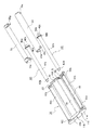
図1に示すように、本実施形態のリボンカセット10は、略矩形状をした樹脂製のカセットケース11を有している。このカセットケース11は、円筒状をした第1の収納部12と、この第1の収納部12と所定の間隔をもって配置された、同じ円筒状をした第2の収納部13と、後述するプリンタ100のリボンカセット装着部120内に挿入される前記第1および第2の収納部12、13の先端部を繋ぐ第1の連結部材14Aと、前記第1および第2の収納部13の後端部を繋ぐ第2の連結部材14Bを有し(以下、必要の応じて第1および第2の連結部材を一対の連結部材14という)、全体の断面形状を略クランク状に形成されている。そして、前記カセットケース11には、その中央に前記一対の連結部材14、第1の収納部12および後述する壁部18に囲まれた矩形状の開孔部15と、第1および第2の収納部12、13の後端部およびそれらの後端部を繋ぐ前記第2の連結部材14Bをそれぞれ連結して一体化した略楕形状の側板部11aとが形成されている。
Hereinafter, an embodiment of a ribbon cassette of the present invention and an embodiment of a printer will be described respectively.
Ribbon cassette:
As shown in FIG. 1, the
前記側板部11aには、所定のピッチ寸法で第3および第4位置決め孔11b、11cが形成されており、前記第3位置決め孔11bに、後述するプリンタ100側の第3位置決めピン105aが嵌合可能になっていると共に、第4位置決め孔11cに、後述する第4位置決めピン105bが嵌合可能になっている。なお、前記開孔部15に対応する空間は、プリンタ100のラインヘッドであるサーマルヘッドを配置させる第1の空間部17Aとされている。また、前記側板部11aには、リボンカセット11をリボンカセット装着部120内に挿入した状態で固定ロックするための、後述する係止爪45が係止する係止孔(係止部材)44が形成されている。
The side plate portion 11a is formed with third and fourth positioning holes 11b and 11c with a predetermined pitch dimension, and a third positioning pin 105a on the
そして、図2に示すように、前記第1の収納部12は、円筒状をした周壁部12aの径の大きい側の縁部に、外方に僅かに延びたテーパー状のフランジ部26がその縁部に沿って設けられており、そのフランジ部26の両端が一対の連結部材14と一体に連結している。これに対して、周壁部12aの径の小さい側の縁部12cは、周壁部12aの径の大きい側の縁部(フランジ部26)に対して、内方に入り込む渦巻き状となるように対向配置されている。周壁部12aのフランジ部26と縁部12c間は、記録に供するインクリボンRを導出するための送出し口21となっている。また、第1の収納部12には、前記側板部11aと対向させて、前記周壁部12aの他端面に円形の側面部12bが設けられており、この側面部12bには円形をした開口部20が形成されている。また、この側面部12bには不図示の第1位置決め孔が形成されており、後述するプリンタ100側の不図示の第1位置決めピンが嵌合可能になっている。
As shown in FIG. 2, the
一方、第2の収納部13には、その周壁部13aの一方の縁部から一対の連結部材14に向けて延設した平板状をした延設部13sが一体に形成されている。また、第2の収納部13は、前記側板部11aと対向させて、円筒状の前記周壁部13aの他端面に円形の側面部13bが設けられており、この側面部13bは円形をした開口部28が形成されている。また、この側面部13bにも不図示の第2位置決め孔が形成されており、後述するプリンタ100側の不図示の第2位置決めピンが嵌合可能になっている。
On the other hand, the
そして、前記一対の連結部材14には、この一対の連結部材14間を一部において橋架する平板状の壁部18が設けられている。前記壁部18は、第2の収納部13の周壁部13aとの間に、後述するプリンタ100の記録部用紙搬送ユニット130の少なくとも開放端辺部分に配設された従動ローラ取付板133を位置させる第2の空間部17Bを形成するようにして前記周壁部13aと対向配置されており、前記延設部13sに対して略直角に折り曲げたように、延設部13sの先端部分と連続して一体に形成されている。なお、前記プリンタの記録部用紙搬送ユニット130は、前記インクリボンRの幅方向に延在し、図示しない駆動源により正逆回転自在に軸支された用紙搬送ローラ131、同じく前記インクリボンRの幅方向に延在し、前記用紙搬送ローラ131と当接して従動回転可能に支持された従動ローラ132、および前記インクリボンRの幅方向に延在し、前記従動ローラ132を前記用紙搬送ローラ131に対してバネ等の付勢部材で用紙搬送ローラ側へ付勢し、接離自在に支持する従動ローラ取付板133を前記壁部18に沿わせて順に配置させている。そして、前記第2の空間部17B内には主に、その解放端側に配設された前記従動ローラ取付板133が臨むことになる(図8参照)。
The pair of connecting members 14 are provided with
前記壁部18の先端側の縁部(第1の支持部)18aは丸めた形状とされており、インクリボンRが摺接する際の支持部とされている。さらに、第2の収納部13には、その周壁部13aの自由端である他方の縁部に前記延設部13sと対向配置された平板状をした延設片13tが一体に設けられている。そして、周壁部13aの延設片13tと壁部18間は、第2の収納部13内に配設された巻取り軸42に記録に使用されたインクリボンRを巻取るための巻取り口27とされている。
An edge portion (first support portion) 18a on the front end side of the
そして、本実施形態のリボンカセット10は、前記リボンカセット11の前記第2の空間部17Bに対向する、前記壁部18に連接された前記第1の連結部材14Aの連接面(壁部連接面という)に凸部Sが形成されており、該リボンカセット10がプリンタ100のリボンカセット装着部120内に装着された際に前記第2の空間部17Bに配置される従動ローラ取付板133に前記凸部Sの頂部を当接させることにより、前記壁部18と前記記録部用紙搬送ユニット130との間にインクリボンRの搬送経路となる一定以上の間隙を常に確保するようになされている。
The
ここで、前記カセットケース11は、図4に示すように、1つの下ケース32と、2つの上ケース(第1の上ケース33および第2の上ケース34)との3部品から構成されている。したがって、前記第1の収納部12は、下ケース32の一部(後述する第1の半円筒部32a)と、その上半分を構成する第1の上ケース33とで構成されていて、前記第2の収納部13は、下ケース32の他部(後述する第2の半円筒部32b)と、その上半分を構成する第2の上ケース34とで構成されている。前記下ケース32は、中央に前記開孔部15が形成されていて、その両側に半円筒状をした第1の半円筒部32aと、同じく半円筒状をした第2の半円筒部32bと、これら第1および第2の半円筒部32a,32b間を繋ぐ前記一対の連結部材14と、前記側板部11aとを有している。
Here, as shown in FIG. 4, the cassette case 11 is composed of three parts: one
そして、前記第2の収納部13に一体に形成された延設部13sと、これに対向配置された延設片13tとにより構成されるインクリボンRの搬送経路内には、前記延設部13sに沿うように、第2の支持部としての回転可能な金属製のシャフト19が側板部11aおよび側面部12b(下半分)を橋架して取付けられている。前記シャフト19にはインクリボンRが摺接するようになっている。よって、摺接抵抗を減らしたシャフト19にあっては回転しないものであってもよい。また、インクリボンRが摺接するシャフト19を省略し、延設部13sの先端を丸めて摺接抵抗を減らし、その先端部分を第2の支持部としてインクリボンRが直接摺接するようにしてもよい。
The extension portion is formed in the transport path of the ink ribbon R formed by the
そして、前記第1および第2の半円筒部32a、32bの周壁部内壁には、側板部11aに対向して、U字形状をした第1の支持壁32j、32pがそれぞれ設けられている。この第1の支持壁32j、32pと側板部11aとの間には、第1および第2の半円筒部32a、32bの周壁部からそれぞれ内方に切り起こされた、弾性を有するモールド片32mが前記側板部11aと第1の支持壁32j、32pとの間に一定の間隔をもって一体に形成されている。また、第1および第2の半円筒部32a、32bは、その周壁部内壁にU字状をした第2の支持壁32k、32qを周壁部の端面を形成する側面部13bと一定の間隔をもって一体に設けている。そして、第1および第2の支持壁32k、32qの壁面部には、第1の支持壁32j、32pに対向して、断面が三角形をした係合突起32nが突設されている。なお、図5および図6には、第2の半円筒部32b内の構成を代表的に図示する。
And the U-shaped
そして、図4に示すように、前記第1の上ケース33は、その周壁部の両端縁に弾性を有する係合爪33d、33dが設けられており、前記第2の上ケース34は、その周壁部の両端縁に弾性を有する係合爪34d、34eがそれぞれ設けられている。
As shown in FIG. 4, the first
また、図4に示すように、送出し軸40および巻取り軸42はともに同じ大きさをした樹脂製の略円筒部材からなり、中央に設けられた筒状の基部40a、42aと、一端に設けられた基部40a,42aの外径よりも径の小さな小径部40b,42bと、他端に設けられた基部40a,42aよりも径の大きな大径部40c、42cとから構成されている。そして、これら大径部40c、42cには、基部40a,42aとの境に鍔状をしたフランジ部40d、42dが設けられており、フランジ部40d、42dの外方側表面部には、複数の矩形状をした矩形溝40e,42eがそれぞれ形成され、軸の周囲に均等に配列されている。そして、送出し40の基部40aには、インクリボンRが巻回されるようになっていて、そのインクリボンRの先端側縁部から巻取り軸42の基部42aに巻回されるようになっている。前記送出し軸40、巻取り軸42の各矩形溝40e,42eと、第2の支持壁部32k、32qの各係合突起32nとが噛合うことにより、確実に係止して、未使用時、例えば、リボンカセット10を運搬するときに、インクリボンRがたるんでカセットケース11に擦らないようにすることができる。
As shown in FIG. 4, the
そして、前記リボンカセット10は、次のようにして組立てられている。すなわち、図4に示すように、先ず下ケース32を準備して、下ケース32の第1の半円筒部32a内に送出し軸40を上方から挿入する。このとき、前記モールド片32mに送出し軸40の小径部40bの先端を弾接させながら、下ケース32の第1の支持壁32jに巻取り軸40の小径部40bを当接させ、第2の支持壁32k、および側面部13bの開口部20内に送出し軸40の大径部40cをそれぞれ当接させる。
The
次に、送出し軸40に巻回されたインクリボンRの先端を第2の半円筒部32bまで引っ張り、この送出し軸40を収納した下ケース32に第1の上ケース33を重ね、各係合爪33d、33dを下ケース32の図示しない孔部に嵌着させて取付け固定する。
Next, the tip of the ink ribbon R wound around the
次に、巻取り軸42を準備する。すなわち、インクリボンRを巻取り軸42に巻回するべく導出させるために、まず、モールド片32mを送出し軸40で回転軸方向に押圧して、下ケース32の係合突起32nと巻取り軸40の矩形溝40eとの係合を解除し、インクリボンRを巻取り軸42の方へさらに引っ張る。前記送出し口21から導出されたインクリボンRは、前記第1の支持部としての壁部18の先端側の縁部18aを経て、その先端部分をシャフト19に巻回して摺接させ、その先端を図示しない接着剤にて巻取り軸42に貼り付け、数回巻いて巻き付け固定する。
Next, the winding
次に、下ケース32の第2の半円筒部32b内において、モールド片32mに巻取り軸42の小径部42bの先端を弾接させ、第1の支持壁32pに巻取り軸42の小径部42bを、第2の支持壁32qおよび側面部13bの開口部28内に巻取り軸42の大径部42cをそれぞれ当接させる。その後、送出し40および第1の上ケース33、送出し軸42が既に組み込まれ、一体とされた下ケース32に、第2の上ケース34をその係合爪34e,34eを介して確実に取付け固定させる。
Next, in the second
このようにして完成されたリボンカセット10においては、前記インクリボンRは、前記送出し軸40の送出し口21からテーパー状のフランジ部26の突出方向へ引き出され、サーマルヘッドが位置する第1の空間部となる前記開孔部15内に露出される。その後、前記第2の支持部としての壁部18に形成された先端側の縁部18aに摺接させて折り曲げられ、カセットケース11の壁部18に沿って搬送され、前記巻取り口27部分で第2の支持部としてのシャフト19に摺接させて約90°折り曲げられる。すなわち、第1の支持部としての壁部18の縁部18aと第2の支持部としてのシャフト19によってクランク状に形成された搬送経路を辿って第2の収納部13内に回収され、前記巻取り軸42に巻回される。このとき、記録に供されたインクリボンRは、前記シャフト19に摺接することにより一定のテンションが付加されることとなる。
In the
次に、このような構成のリボンカセット10を装着するプリンタ100の概略構造について説明する。
Next, a schematic structure of the
本実施形態のリボンカセット10を装着するプリンタ100は、前述の従来例に用いたプリンタの構成と同じでよい。すなわち、前記プリンタ100は、図7に示すように、金属板からなる筐体102が配設され、この筐体102は、底板102a、および互いに対向する前側板102bと後側板102cとにより略コ字状に形成されている。そして、前記筐体102には、記録部に配設された不図示の平板状のプラテンに対してヘッドアップ/ダウン可能とされたラインヘッドからなるサーマルヘッドを下部側に取り付けたヘッド取付台101が配設されている。
The
そして、前記記録部の近傍には、前記記録部に対する給紙と排紙を行なう記録部用紙搬送ユニット130が配設されている。前記記録部用紙搬送ユニット130は、該プリンタ100に装着されるリボンカセット10に収納されるインクリボンRの幅方向に延在し、図示しない駆動源により正逆回転自在とされて軸支された用紙搬送ローラ131、前記インクリボンRの幅方向に延在し、前記用紙搬送ローラ131と当接して従動回転可能に支持された従動ローラ132、および前記インクリボンRの幅方向に延在し前記従動ローラ132を前記用紙搬送ローラ131に対して接離自在に支持する従動ローラ取付板133を重ねて順に配置させた状態で構成されている。
In the vicinity of the recording unit, a recording unit
また、前側板102bには、後述のカセット装着部103にリボンカセット1を前記先端部側から挿入可能な、略めがね状の挿入口102dが形成されている。また、前側板102bと後側板102cとの間で底板102a上には、リボンカセット1を装着可能な空洞状のカセット装着部103が形成されている。前記後側板102cには、カセット装着部103内に突出し、リボンカセット10に収納される送出し軸40および巻取り軸42にそれぞれ嵌合する送出しボビンおよび巻取りボビン(いずれも不図示)が回転可能に配設されている。そして、前記後側板102cの内面には、リボンカセットの先端側の位置決めを行うための第1および第2位置決めピン(いずれも不図示)が所定のピッチ寸法で立設されている。そして、前記カセット装着部103には、リボンカセット10がその送出し軸40を収納した第1の収納部12をカセット装着部103の図示右側の第1の空洞部103aに位置させ、巻取り軸42を収納した第2の収納部13が図示左側の第2の空洞部103bに位置させるようにして装着される。そして、前記カセット装着部103は、プリンタ100が駆動される際には、第1および第2収納部12、13内において各係合突起32nと矩形溝40e、42eとの噛合いが解除され、図示しない回転駆動機構によって、その送出し軸40および巻取り軸42を回転可能とされている。
Further, the front plate 102b is formed with a substantially glasses-like insertion port 102d through which the
また、筐体102の前側板102bの前面側には、樹脂材料からなるカセットガイド104が取り付けられており、カセット装着部103に挿入するリボンカセット1が挿入口102dで擦れて傷が付くのを防止するようになっている。また、前記前側板102bには、リボンカセット10をリボンカセット装着部103内に挿入した状態で固定ロックするための係止爪(係止部材)45が配設されている。さらに、前側板102bの前面側の前記カセットガイド104の前記記録部用紙搬送ユニット130の側方となる位置には、第3位置決めピン105aが立設されており、第1空洞部103aに隣接する前側板102bには、第4位置決めピン105bが立設されている。
Also, a
また、プリンタ100のカセット装着部103の奥側には、カセット装着部103に装着したリボンカセット10を検出可能なカセット検出手段(図示せず)が配設されている。前記カセット検出手段は、カセット装着部103に装着したリボンカセット10のカセットケース11の側面部12b、13bが押圧操作可能なスイッチ(図示せず)からなり、カセット装着部103に挿入したリボンカセット1がスイッチを押圧操作することによって、カセット装着部103にリボンカセット1が装着されたことを検出できるようになっている。
Further, a cassette detection means (not shown) capable of detecting the
そして、このような構成のプリンタ100に本実施形態のリボンカセット1を装着する場合には、プリンタ100の挿入口102dから、リボンカセット10をカセット装着部103に挿入する。このとき、リボンカセット10は、送出し軸40を収納した第1の収納部12が第1の空洞部103aに、巻取り軸42を収納した第2の収納部13が第2の空洞部103bに位置するとともに、前記第2の空間部17B内に、前記記録部用紙搬送ユニット130の開放端側を臨ませるようにして挿入する。その際、本実施形態においては、リボンカセット10の前記凸部Sを従動ローラ取付板133と摺接させるようにすることにより、リボンカセット10を正しい装着位置に容易に案内することができる。そして、リボンカセット10の挿入方向における先端部においては、前記第1の収納部に形成された開口部20に配設された送出し軸40の大径部内40cに、プリンタ100側のインクリボン搬送機構としての送出し用コアを嵌合させ、前記第2の収納部に形成された開口部28に配設された巻取り軸42の大径部内42cに、プリンタ100側のインクリボン搬送機構としての巻取り用コアを嵌合させ、リボンカセット10の挿入方向における後端部においては、前記側板部11aの前記第1位置決め孔11bにはプリンタ100の第3位置決めピン105aを、第2位置決め孔11cにはプリンタ100の第4位置決めピン105bを嵌合させつつ、前記側板部11aをプリンタ100の前側板102aに当接させた状態で、前記係止手段110、111を以て固定することができる。
When the
このようにしてプリンタ100に固定されたリボンカセット10は、図8に示すように、前記第2の空間部17Bに対向する前記第1の連結部材14Aの壁部連接面に形成された凸部Sが、前記第2の空間部17Bに配置される従動ローラ取付板133に対し、その頂部を当接させることで、前記壁部18と前記記録部用紙搬送ユニット130との間にインクリボンRの搬送経路となる間隙を確保することができる。
As shown in FIG. 8, the
そして、カセット装着部103にリボンカセット10が正しく装着されると、前記カセット検出手段のスイッチがカセットケース11の側面部12b、13bによって押圧操作され、プリンタ100に対応する種類のリボンカセット1がカセット装着部103に装着されたことが検出される。
When the
ここで、このようなプリンタ100に本発明のリボンカセット10を装着した場合の記録動作を説明する。
Here, a recording operation when the
リボンカセット装着部120内に所望の色のインクリボンRを備えたリボンカセット10が装着され、複数の印刷情報から所望の印刷情報が選択されると、前記プリンタ100は、先ず、不図示の記録用紙の給紙機構により搬送させて、記録部用紙搬送ユニット130の用紙搬送ローラ131とこの用紙搬送ローラ131に圧接する従動ローラ132間に圧接挟持させる。そして、用紙搬送ローラ131を正方向へ回転駆動させることにより、記録用紙を離間状態にあるプラテンとサーマルヘッドとの間に搬送する。そして、記録用紙の印刷開始位置をサーマルヘッドの発熱素子が形成された部分に位置合わせした状態で、用紙搬送ローラ131と従動ローラ132の回転を停止し、サーマルヘッドをプラテン側に移動させてヘッドダウン状態とするとともに、前記開孔部15に臨むインクリボンRと記録用紙とを重ねた状態で、それらをプラテンに圧接し、所望の印刷情報にしたがってサーマルヘッドの発熱素子を選択的に発熱させ、インクリボンRのインクを記録用紙に熱転写して所望の印刷記録を行う。なお、印刷記録後、プラテンはサーマルヘッドに対して元の離間位置に戻し、記録用紙は、用紙搬送ローラ131が逆方向へ回転駆動することにより、回転する従動ローラ132に弾接しながら逆搬送され、記録部外へ排出される。
When a
このとき、本実施形態のリボンカセット10においては、印刷記録に使用されるインクリボンRは、前述のように、前記送出し軸40の送出し口21からテーパー状のフランジ部26の突出方向へ引き出され、サーマルヘッドが位置する第1の空間部17Aの前記開孔部15内に露出される。その後、前記第2の支持部としての壁部18に形成された先端側の縁部18aに摺接させて折り曲げられ、カセットケース11の壁部18に沿って搬送され、前記巻取り口27部分で第2の支持部としてのシャフト19に摺接させて約90°折り曲げられた状態、すなわち、第1の支持部としての壁部18の縁部18aと第2の支持部としてのシャフト19によってクランク状に形成された搬送経路を辿って第2の収納部13内に回収され、前記巻取り軸42に巻回される。このとき、記録に供されたインクリボンRは、壁部18の縁部18aと前記シャフト19によりクランク状にその走行路が形成された搬送経路を搬送され、前記シャフト19に摺接することにより一定のテンションが付加されることとなる。よって、インクリボンRの弛みの発生を抑えることができ、このようにインクリボンRを弛みなく引っ張った状態で巻取搬送することにより、プリンタ100の記録部用紙搬送ユニット130に対し、インクリボンRが巻付いたり、吸い寄せられたりすることを防止でき、インクリボンRの巻取り搬送をスムーズに行うことができる。
At this time, in the
そして、本実施形態のリボンカセットは、前述のように、前記第1の連結部材14Aの前記第2の空間部17Bに対向する壁部連接面に形成された凸部Sの頂部を前記第2の空間部17Bに配置される従動ローラ取付板133に当接させることにより、前記壁部18と前記記録部用紙搬送ユニット130との間に凸部Sの突出寸法分の間隙がインクリボンRの搬送経路にースが常に確保されるので、仮に、インクリボンRの巻取動作等により、リボンカセット11にブレや振動が生じても、帯電したインクリボンRがプリンタ100の記録部用紙搬送ユニット130に巻付いたり、吸い寄せられたりすることを防止することができる。
プリンタ:
次に、本発明のプリンタの実施形態について説明する。なお、以下に示す各部材の符号は、前述した本発明のリボンカセット10とそのリボンカセット10を装着するプリンタ100と共通の部分については同じ符号を使用する。
In the ribbon cassette of the present embodiment, as described above, the top portion of the convex portion S formed on the wall connecting surface facing the second space portion 17B of the first connecting
Printer:
Next, an embodiment of the printer of the present invention will be described. In addition, the code | symbol of each member shown below uses the same code | symbol about the part which is common in the
本発明のプリンタ100は、前述の従来例において説明した構成のリボンカセット10を装着するためのプリンタ100であり、前記リボンカセット10は、前述の本発明のリボンカセット10において、前記第2の連結部材14Bの前記第2空間部17Bに対向する壁部連接面に凸部Sが形成されていないタイプのリボンカセット10である。
The
すなわち、このリボンカセット10は、第1の収納部12と、この第1の収納部12と所定の間隔を設けて配置された第2の収納部13と、プリンタ100のリボンカセット装着部120内に挿入される前記第1および第2の収納部12、13の先端部を連結する第1の連結部材14Aと、前記第1および第2の収納部12、13の後端部を連結する第2の連結部材14Bを有するカセットケースを有している。また、前記リボンカセット10は、前記第1および第2の収納部12、13内にそれぞれ回転可能に収納された送出し軸40および巻取り軸42と、該送出し軸40および前記巻取り軸42にそれぞれ巻装され、前記送出し軸40から導出されて前記巻取り軸42に巻取り可能とされた幅広なインクリボンRとを備え、前記一対の連結部材14間を橋架する壁部18により構成された第1の支持部を設けるとともに、前記第1の支持部と対応させて巻取り軸42が収納される第2の収納部13にインクリボンRの幅方向に沿った第2の支持部(19)を設け、前記送出し軸40から導出され、記録に供されたインクリボンRを前記第1の支持部(18a)にて折り曲げ、続いて前記第2の支持部(19)にてさらに折り曲げて搬送し、前記巻取り軸42に巻回するようになされている。
That is, the
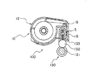
そして、本実施形態のプリンタ100は、前述した本発明のインクリボンに関する実施形態中のプリンタ100の構成とは、前記記録部用紙搬送ユニット130の構成を異ならせるものである。すなわち、本実施形態のプリンタ100は、図9に示すように、前記従動ローラ取付板133の、前記第2の空間部17Bに対向し前記リボンカセット10の第1の連結部材14Aと対向する面に、凸部Sが形成されており、前記第1の連結部材14Aに頂部を当接させることにより前記壁部18と前記記録部用紙搬送ユニット130との間にインクリボンRの搬送経路となる間隙を確保するように構成されている。
The
このような構成のプリンタにおいては、図10に示すように、リボンカセット10の装着時には、前記従動ローラ取付板133に形成された凸部Sの頂部を前記リボンカセット10の前記第1の連結部材14Aに当接させることにより、前記壁部18と前記記録部用紙搬送ユニット130との間にインクリボンRの搬送経路となる間隙を確保することができる。よって、仮に、インクリボンRの巻取動作により、リボンカセット10にブレや振動が生じても、前記送出し軸40から導出され、前記第1の支持部(18a)にて折り曲げられ、前記第2の支持部(19)へ向かって搬送されるインクリボンRと前記記録部用紙搬送ユニット130との間に間隙が形成されていることにより、帯電したインクリボンRがプリンタ100の記録部用紙搬送ユニット130に巻付いたり、吸い寄せられたりすることを防止することができ、インクリボンRの巻取り搬送をスムーズに行うことができる。
In the printer having such a configuration, as shown in FIG. 10, when the
なお、本発明は、前述した実施の形態に限定されるものではなく、必要に応じて種々の変更が可能である。 In addition, this invention is not limited to embodiment mentioned above, A various change is possible as needed.
10 リボンカセット
11 カセットケース
11a 側板部
11b 第1位置決め孔
11c 第2位置決め孔
12 第1の収納部
12a 周壁部
12b 側面部
12c 縁部
13 第2の収納部
13a 周壁部
13b 側面部
13s 延設部
13t 延設片
14A 第1の連結部材
14B 第2の連結部材
15 開孔部
17A 第1の空間部
17B 第2の空間部
18 壁部
18a 縁部(第1の支持部)
19 シャフト(第2の支持部)
20 開口部
21 送出し口
26 フランジ部
27 巻取り口
28 (第2の収納部の)開口部
32 下ケース
32a 第1の半円筒部
32b 第2の半円筒部
32j、32p 第1の支持壁
32k、32q 第2の支持壁
32m モールド片
32n 係合突起
33 第1の上ケース
34 第2の上ケース
40 送出し軸
40a 基部
40b 小径部
40c 大径部
40d フランジ部
40e 矩形溝
42 巻取り軸
42a 基部
42b 小径部
42c 大径部
42d フランジ部
42e 矩形溝
100 プリンタ
101 ヘッド取付台
102 筐体
102a 底板
102b 前側板
102c 後側板
102d 挿入口
103 カセット装着部
103a 第1の空洞部
103b 第2の空洞部
104 カセットガイド
105a 第1位置決めピン
110 係止手段
111 係止手段
120 リボンカセット装着部
130 記録部用紙搬送ユニット
131 用紙搬送ローラ
132 従動ローラ
133 従動ローラ取付板
S 凸部
R インクリボン
DESCRIPTION OF
19 Shaft (second support part)
20
Claims (3)
前記第1および第2の収納部内にそれぞれ回転可能に収納された送出し軸および巻取り軸と、該送出し軸および前記巻取り軸にそれぞれ巻装され、前記送出し軸から導出されて前記巻取り軸に巻取り可能とされたインクリボンとを備え、
前記第1および第2の連結部材間を橋架する壁部により構成された第1の支持部を設けるとともに、前記第1の支持部と対応させて巻取り軸が収納される第2の収納部にインクリボンの幅方向に沿った第2の支持部を設け、前記送出し軸から導出され、記録に供されたインクリボンが前記第1の支持部にて折り曲げられ、続いて前記第2の支持部にてさらに折り曲げられて搬送され、前記巻取り軸に巻回されるようになされているとともに、
前記壁部と第2の収納部との間に、プリンタの前記インクリボンの幅方向に延在し回転自在に軸支された用紙搬送ローラ、前記インクリボンの幅方向に延在し前記用紙搬送ローラと当接して従動回転可能に支持された従動ローラ、および前記インクリボンの幅方向に延在し前記従動ローラを前記用紙搬送ローラに対して接離自在に支持する従動ローラ取付板を前記壁部に沿って順次配置させてなる記録部用紙搬送ユニットの一部を臨ませる空間部が形成されてなるリボンカセットにおいて、
前記第1の連結部材の前記空間部に対向する壁部連接面に、前記リボンカセットがプリンタのリボンカセット装着部内に装着された際に前記空間部に配置される従動ローラ取付板に対しその頂部を当接させる凸部が形成されていることを特徴とするリボンカセット。 A first storage section; a second storage section that is inserted into the ribbon cassette mounting section of the printer together with the first storage section disposed at a predetermined interval from the first storage section; and the first storage section. And a first connecting member for connecting the leading end portions in the insertion direction of the second storage portion into the ribbon cassette mounting portion, and a connection between the rear end portions in the inserting direction of the first and second storage portions. A cassette case having a second connecting member to be
The feeding shaft and the winding shaft that are rotatably accommodated in the first and second storage portions, respectively, wound around the feeding shaft and the winding shaft, and led out from the feeding shaft to be An ink ribbon that can be wound on a winding shaft;
A second storage portion that is provided with a first support portion configured by a wall portion that bridges between the first and second connecting members, and that accommodates the winding shaft in correspondence with the first support portion. The ink ribbon is provided with a second support portion along the width direction of the ink ribbon, the ink ribbon led out from the feed shaft and used for recording is bent at the first support portion, and then the second ribbon is provided. It is further bent and conveyed at the support part, and is wound around the winding shaft,
A paper conveying roller extending in the width direction of the ink ribbon of the printer and rotatably supported between the wall portion and the second storage portion, and extending in the width direction of the ink ribbon and conveying the paper And a driven roller mounting plate, which is supported so as to be driven to rotate in contact with the roller, and a driven roller mounting plate that extends in the width direction of the ink ribbon and supports the driven roller so as to contact with and separate from the paper transport roller. In the ribbon cassette formed with a space part that faces a part of the recording part paper transport unit arranged sequentially along the part,
When the ribbon cassette is mounted in the ribbon cassette mounting portion of the printer on the wall connecting surface facing the space portion of the first connecting member, the top portion of the driven roller mounting plate disposed in the space portion. A ribbon cassette characterized in that a convex part is formed to abut against the ribbon cassette.
前記第1および第2の連結部材間を橋架する壁部により構成された第1の支持部を設けるとともに、前記第1の支持部と対応させて巻取り軸が収納される第2の収納部にインクリボンの幅方向に沿った第2の支持部を設け、前記送出し軸から導出され、記録に供されたインクリボンが前記第1の支持部にて折り曲げられ、続いて前記第2の支持部にてさらに折り曲げられて搬送され、前記巻取り軸に巻回されるようになされており、前記壁部と第2の収納部との間に空間部が形成されてなるリボンカセットを、
前記空間部に、プリンタの前記インクリボンの幅方向に延在し回転自在に軸支された用紙搬送ローラ、前記インクリボンの幅方向に延在し前記用紙搬送ローラと当接して従動回転可能に支持された従動ローラ、および前記インクリボンの幅方向に延在し前記従動ローラを前記用紙搬送ローラに対して接離自在に支持する従動ローラ取付板を前記壁部に沿って順次配置させてなる記録部用紙搬送ユニットの一部を臨ませるようにして筐体の側壁に形成された挿入口から挿入し、筐体内のカセット装着部に装着させるように構成されたプリンタにおいて、
前記従動ローラ取付板の前記空間部に対向し、前記リボンカセットの第2の連結部材と対向する面に、リボンカセットの前記第1の連結部材にその頂部を当接させる凸部が形成されていることを特徴とするプリンタ。
A first storage section; a second storage section that is inserted into the ribbon cassette mounting section of the printer together with the first storage section disposed at a predetermined interval from the first storage section; and the first storage section. And a first connecting member for connecting the leading end portions in the insertion direction of the second storage portion into the ribbon cassette mounting portion, and a connection between the rear end portions in the inserting direction of the first and second storage portions. A cassette case having a second connecting member, a feed shaft and a take-up shaft rotatably accommodated in the first and second storage portions, respectively, and winding on the feed shaft and the take-up shaft, respectively. And an ink ribbon that is led out from the feed shaft and wound on the take-up shaft,
A second storage portion that is provided with a first support portion configured by a wall portion that bridges between the first and second connecting members, and that accommodates the winding shaft in correspondence with the first support portion. The ink ribbon is provided with a second support portion along the width direction of the ink ribbon, the ink ribbon led out from the feed shaft and used for recording is bent at the first support portion, and then the second ribbon is provided. A ribbon cassette that is further bent and conveyed by a support portion and wound around the take-up shaft, and in which a space portion is formed between the wall portion and the second storage portion,
A paper conveying roller that extends in the width direction of the ink ribbon of the printer and is rotatably supported in the space portion, and extends in the width direction of the ink ribbon and abuts on the paper conveying roller to be driven to rotate. A driven roller that is supported, and a driven roller mounting plate that extends in the width direction of the ink ribbon and supports the driven roller so as to come into contact with and separate from the paper transport roller are sequentially arranged along the wall portion. In a printer configured to be inserted into an insertion port formed on the side wall of the housing so that a part of the recording unit paper transport unit faces and to be mounted on a cassette mounting portion in the housing,
A convex portion is formed on the surface of the driven roller mounting plate that faces the space portion and faces the second connecting member of the ribbon cassette so that the top portion of the ribbon cassette comes into contact with the first connecting member. A printer characterized by being.
Priority Applications (4)
| Application Number | Priority Date | Filing Date | Title |
|---|---|---|---|
| JP2006143152A JP4621168B2 (en) | 2006-05-23 | 2006-05-23 | Ribbon cassette and printer |
| EP07010081A EP1859950A2 (en) | 2006-05-23 | 2007-05-21 | Ribbon cassette and printer |
| US11/752,171 US7736076B2 (en) | 2006-05-23 | 2007-05-22 | Ribbon cassette and printer |
| CN200710104196A CN100586735C (en) | 2006-05-23 | 2007-05-23 | Ribbon cassette and printer |
Applications Claiming Priority (1)
| Application Number | Priority Date | Filing Date | Title |
|---|---|---|---|
| JP2006143152A JP4621168B2 (en) | 2006-05-23 | 2006-05-23 | Ribbon cassette and printer |
Publications (2)
| Publication Number | Publication Date |
|---|---|
| JP2007313679A JP2007313679A (en) | 2007-12-06 |
| JP4621168B2 true JP4621168B2 (en) | 2011-01-26 |
Family
ID=38229829
Family Applications (1)
| Application Number | Title | Priority Date | Filing Date |
|---|---|---|---|
| JP2006143152A Expired - Fee Related JP4621168B2 (en) | 2006-05-23 | 2006-05-23 | Ribbon cassette and printer |
Country Status (4)
| Country | Link |
|---|---|
| US (1) | US7736076B2 (en) |
| EP (1) | EP1859950A2 (en) |
| JP (1) | JP4621168B2 (en) |
| CN (1) | CN100586735C (en) |
Families Citing this family (7)
| Publication number | Priority date | Publication date | Assignee | Title |
|---|---|---|---|---|
| JP2010253846A (en) * | 2009-04-27 | 2010-11-11 | Sony Corp | Ink ribbon cartridge |
| JP2010253847A (en) * | 2009-04-27 | 2010-11-11 | Sony Corp | Ink ribbon cartridge |
| CN104108249B (en) * | 2013-04-17 | 2016-10-05 | 山东新北洋信息技术股份有限公司 | The installation method of ribbon cartridge, thermal transfer printer and this ribbon cartridge |
| USD761351S1 (en) * | 2013-09-20 | 2016-07-12 | Canon Kabushiki Kaisha | Ink ribbon cassette for printer |
| JP6270430B2 (en) * | 2013-11-22 | 2018-01-31 | キヤノン株式会社 | Ink ribbon cassette and printing apparatus |
| JP6641811B2 (en) * | 2015-09-08 | 2020-02-05 | マックス株式会社 | Ink ribbon, ink ribbon cassette and printer |
| JP7414560B2 (en) * | 2020-01-31 | 2024-01-16 | キヤノン株式会社 | ink cassettes and printers |
Citations (2)
| Publication number | Priority date | Publication date | Assignee | Title |
|---|---|---|---|---|
| JP2001205905A (en) * | 2000-01-28 | 2001-07-31 | Alps Electric Co Ltd | Ribbon cassette |
| JP2004223731A (en) * | 2003-01-20 | 2004-08-12 | Alps Electric Co Ltd | Thermal printer |
Family Cites Families (4)
| Publication number | Priority date | Publication date | Assignee | Title |
|---|---|---|---|---|
| US5959652A (en) * | 1997-07-11 | 1999-09-28 | Pitney Bowes Inc. | Thermal ink ribbon cassette for mailing machines |
| JP2003118193A (en) * | 2001-10-11 | 2003-04-23 | Alps Electric Co Ltd | Ink ribbon cassette and thermal transfer printer using the same |
| JP2007021940A (en) * | 2005-07-19 | 2007-02-01 | Alps Electric Co Ltd | Ink ribbon cassette |
| US7522179B2 (en) * | 2006-07-03 | 2009-04-21 | Eastman Kodak Company | Universal donor cartridge |
-
2006
- 2006-05-23 JP JP2006143152A patent/JP4621168B2/en not_active Expired - Fee Related
-
2007
- 2007-05-21 EP EP07010081A patent/EP1859950A2/en not_active Withdrawn
- 2007-05-22 US US11/752,171 patent/US7736076B2/en not_active Expired - Fee Related
- 2007-05-23 CN CN200710104196A patent/CN100586735C/en active Active
Patent Citations (2)
| Publication number | Priority date | Publication date | Assignee | Title |
|---|---|---|---|---|
| JP2001205905A (en) * | 2000-01-28 | 2001-07-31 | Alps Electric Co Ltd | Ribbon cassette |
| JP2004223731A (en) * | 2003-01-20 | 2004-08-12 | Alps Electric Co Ltd | Thermal printer |
Also Published As
| Publication number | Publication date |
|---|---|
| EP1859950A2 (en) | 2007-11-28 |
| CN101077665A (en) | 2007-11-28 |
| US20070274757A1 (en) | 2007-11-29 |
| US7736076B2 (en) | 2010-06-15 |
| JP2007313679A (en) | 2007-12-06 |
| CN100586735C (en) | 2010-02-03 |
Similar Documents
| Publication | Publication Date | Title |
|---|---|---|
| JP4621168B2 (en) | Ribbon cassette and printer | |
| KR102580618B1 (en) | Ribbon cartridge and printing device | |
| JP2001205905A (en) | Ribbon cassette | |
| JP2007216590A (en) | Recording paper ink sheet integrated cassette and printer device using the cassette | |
| JP7073846B2 (en) | Printing cartridges, tape guides and printing equipment | |
| KR102474516B1 (en) | Ribbon Cartridge and Printing Unit | |
| JP2010253846A (en) | Ink ribbon cartridge | |
| JP4285545B2 (en) | Image forming apparatus | |
| JP4018704B2 (en) | Ribbon cassette | |
| JP2006315362A (en) | Ink sheet cartridge | |
| JP2001205881A (en) | Ribbon cassette | |
| JP3782275B2 (en) | Ribbon cassette | |
| US20070274756A1 (en) | Ink ribbon cassette and printer including ink ribbon | |
| JP7295997B2 (en) | ribbon cartridge | |
| JP2001205906A (en) | Ribbon cassette | |
| CN111902293B (en) | Ribbon cartridge | |
| JP5266726B2 (en) | Image forming apparatus | |
| JP4590360B2 (en) | cassette | |
| JP2001205907A (en) | Ribbon cassette and its assembling method | |
| JP2007118360A (en) | Printer | |
| JP3580808B2 (en) | Ink sheet set | |
| JP2001205880A (en) | Ribbon cassette | |
| JP2001277629A (en) | Ink sheet cartridge and exchanging ink sheet set | |
| JPH1138583A (en) | Film supply device | |
| JP2004059284A (en) | Holder of recording medium and recording apparatus |
Legal Events
| Date | Code | Title | Description |
|---|---|---|---|
| A621 | Written request for application examination |
Free format text: JAPANESE INTERMEDIATE CODE: A621 Effective date: 20080905 |
|
| TRDD | Decision of grant or rejection written | ||
| A01 | Written decision to grant a patent or to grant a registration (utility model) |
Free format text: JAPANESE INTERMEDIATE CODE: A01 Effective date: 20101026 |
|
| A01 | Written decision to grant a patent or to grant a registration (utility model) |
Free format text: JAPANESE INTERMEDIATE CODE: A01 |
|
| A61 | First payment of annual fees (during grant procedure) |
Free format text: JAPANESE INTERMEDIATE CODE: A61 Effective date: 20101029 |
|
| FPAY | Renewal fee payment (event date is renewal date of database) |
Free format text: PAYMENT UNTIL: 20131105 Year of fee payment: 3 |
|
| R150 | Certificate of patent or registration of utility model |
Ref document number: 4621168 Country of ref document: JP Free format text: JAPANESE INTERMEDIATE CODE: R150 Free format text: JAPANESE INTERMEDIATE CODE: R150 |
|
| S533 | Written request for registration of change of name |
Free format text: JAPANESE INTERMEDIATE CODE: R313533 |
|
| R350 | Written notification of registration of transfer |
Free format text: JAPANESE INTERMEDIATE CODE: R350 |
|
| LAPS | Cancellation because of no payment of annual fees |