JP4620463B2 - Aerosol dispenser and adapter used for it - Google Patents
Aerosol dispenser and adapter used for it Download PDFInfo
- Publication number
- JP4620463B2 JP4620463B2 JP2004536030A JP2004536030A JP4620463B2 JP 4620463 B2 JP4620463 B2 JP 4620463B2 JP 2004536030 A JP2004536030 A JP 2004536030A JP 2004536030 A JP2004536030 A JP 2004536030A JP 4620463 B2 JP4620463 B2 JP 4620463B2
- Authority
- JP
- Japan
- Prior art keywords
- valve stem
- container
- dispenser
- closed
- dispensing
- Prior art date
- Legal status (The legal status is an assumption and is not a legal conclusion. Google has not performed a legal analysis and makes no representation as to the accuracy of the status listed.)
- Expired - Fee Related
Links
Images


Classifications
-
- B—PERFORMING OPERATIONS; TRANSPORTING
- B65—CONVEYING; PACKING; STORING; HANDLING THIN OR FILAMENTARY MATERIAL
- B65D—CONTAINERS FOR STORAGE OR TRANSPORT OF ARTICLES OR MATERIALS, e.g. BAGS, BARRELS, BOTTLES, BOXES, CANS, CARTONS, CRATES, DRUMS, JARS, TANKS, HOPPERS, FORWARDING CONTAINERS; ACCESSORIES, CLOSURES, OR FITTINGS THEREFOR; PACKAGING ELEMENTS; PACKAGES
- B65D83/00—Containers or packages with special means for dispensing contents
- B65D83/14—Containers or packages with special means for dispensing contents for delivery of liquid or semi-liquid contents by internal gaseous pressure, i.e. aerosol containers comprising propellant for a product delivered by a propellant
- B65D83/44—Valves specially adapted therefor; Regulating devices
- B65D83/52—Valves specially adapted therefor; Regulating devices for metering
- B65D83/54—Metering valves ; Metering valve assemblies
-
- A—HUMAN NECESSITIES
- A61—MEDICAL OR VETERINARY SCIENCE; HYGIENE
- A61M—DEVICES FOR INTRODUCING MEDIA INTO, OR ONTO, THE BODY; DEVICES FOR TRANSDUCING BODY MEDIA OR FOR TAKING MEDIA FROM THE BODY; DEVICES FOR PRODUCING OR ENDING SLEEP OR STUPOR
- A61M15/00—Inhalators
- A61M15/009—Inhalators using medicine packages with incorporated spraying means, e.g. aerosol cans
-
- B—PERFORMING OPERATIONS; TRANSPORTING
- B65—CONVEYING; PACKING; STORING; HANDLING THIN OR FILAMENTARY MATERIAL
- B65D—CONTAINERS FOR STORAGE OR TRANSPORT OF ARTICLES OR MATERIALS, e.g. BAGS, BARRELS, BOTTLES, BOXES, CANS, CARTONS, CRATES, DRUMS, JARS, TANKS, HOPPERS, FORWARDING CONTAINERS; ACCESSORIES, CLOSURES, OR FITTINGS THEREFOR; PACKAGING ELEMENTS; PACKAGES
- B65D83/00—Containers or packages with special means for dispensing contents
- B65D83/14—Containers or packages with special means for dispensing contents for delivery of liquid or semi-liquid contents by internal gaseous pressure, i.e. aerosol containers comprising propellant for a product delivered by a propellant
- B65D83/38—Details of the container body
- B65D83/384—Details of the container body comprising an aerosol container disposed in an outer shell or in an external container
Abstract
Description
本発明は、複数回分の用量の加圧されたエーロゾル配合物を分配するための、特に患者の呼吸器系に投与する薬剤を定量分配するためのディスペンサー、並びにディスペンサーに使用するアダプターに関する。 The present invention relates to a dispenser for dispensing multiple doses of pressurized aerosol formulation, in particular for dispensing a drug to be administered to a patient's respiratory system, as well as an adapter for use in the dispenser.
エーロゾル製薬、および患者に薬剤を吸入投与するための加圧式医薬用ディスペンサーの使用は、一般的であり、更に重要性が増している。 The use of aerosol pharmaceuticals and pressurized pharmaceutical dispensers for inhalation of drugs to patients is common and of increasing importance.
薬剤は、一般に、1種類以上の噴射剤(例えば、クロロフルオロカーボン、更に最近では、噴射剤134a(CF3CH2F)および噴射剤227(CF3CHFCF3)などのハイドロフルオロアルカンを含めた水素含有フルオロカーボンなど)、並びに追加の任意の賦形剤又は構成成分と一緒に配合された後、容器又はバイアル瓶に装填される。容器は、典型的には、閉鎖位置と分配位置との間を移動可能な細長い出口部材又は弁棒を備える分配弁、特に、定量分配弁をフェルールで嵌合されて、分配キャニスターを提供する。分配キャニスターは、典型的にはアダプターと共に使用され、アダプターは、典型的には患者側ポート(例えば、マウスピース、又は鼻に使用するように構成されているポート)を有する。慣用的な押して呼吸する(press−and−breathe)吸入器などの慣用的なディスペンサーでは、アダプターは、典型的には、分配弁の弁棒を受容するように構成されているソケットと、ソケットおよび患者側ポートと開放連通するオリフィスとを有する支持ブロックを備える。 The drug is typically hydrogen, including one or more propellants (eg, chlorofluorocarbons, and more recently hydrofluoroalkanes such as propellant 134a (CF 3 CH 2 F) and propellant 227 (CF 3 CHFCF 3 ). Containing fluorocarbons, etc.), as well as additional optional excipients or components, and then loaded into containers or vials. The container is typically fitted with a ferrule with a dispensing valve, in particular a metering dispensing valve comprising an elongate outlet member or valve stem movable between a closed position and a dispensing position to provide a dispensing canister. Distribution canisters are typically used with an adapter, which typically has a patient-side port (eg, a mouthpiece or a port configured for use with the nose). In conventional dispensers, such as conventional press-and-breath inhalers, the adapter typically includes a socket configured to receive a valve stem of a dispensing valve, and a socket and A support block having a patient side port and an orifice in open communication is provided.
慣用的な分配弁では、弁棒は、典型的には、弁棒が容器に対して外向きに延びている状態でその閉鎖位置(「外側の」閉鎖位置)に付勢されており、弁を作動又は噴射させるため、弁棒を分配位置(「内側の」分配位置)に内向きに押し下げると、1回分の用量を分配することができる。例えば、慣用的な押して呼吸する装置では、患者は、容器をアダプターの支持ブロックの方に押し下げ、従って弁棒を内向きに押下げることによって装置を噴射し、それと同時に吸入する。 In conventional dispensing valves, the valve stem is typically biased to its closed position ("outside" closed position) with the valve stem extending outwardly relative to the container, When the valve stem is pushed inwardly into the dispensing position (the “inner” dispensing position) to actuate or inject, the dose can be dispensed. For example, in a conventional push-and-breath device, the patient injects the device by simultaneously depressing the container toward the support block of the adapter, thus pushing the valve stem inward, and simultaneously inhales.
例えば、米国特許第5,772,085号明細書に開示されているシャトル型の定量分配弁の特定の実施形態など、慣用的な押して噴射する方式で動作しない分配弁もある。代わりに、弁棒は、内側の閉鎖ないし準備位置から外側の分配位置に容器に対して移動する。換言すれば、弁棒が容器に対して外向きに移動すると、分配弁は作動又は噴射する。このような弁の動作には、典型的には、使用者が弁棒を準備位置に内向きに押下げた後、解放することが必要であり、弁棒が分配位置に外向きに移動すると、解放行程中、噴射することができる。 Some dispensing valves do not operate in a conventional push-injection manner, for example, certain embodiments of the shuttle-type metering dispensing valve disclosed in US Pat. No. 5,772,085. Instead, the valve stem moves relative to the container from the inner closed or ready position to the outer dispensing position. In other words, when the valve stem moves outward relative to the container, the dispensing valve is actuated or injected. Such valve operation typically requires the user to push the valve stem inwardly to the ready position and then release it, once the valve stem moves outward to the dispensing position. During the release stroke, it can be injected.
普及していない、解放時の噴射(解放して噴射する操作)は、患者を困惑させる場合があることが認識されている。特に、患者は、慣用的な押して呼吸する型の吸入器(即ち、押して噴射するディスペンサー)を操作すると同時に吸入することを協調させる方法を学ぶ集中訓練を受けることが多く、従って、解放して噴射する操作に基づくディスペンサーの使用に切り替えることは、ほぼ不可能ではなくとも、困難であると思う場合がある。喘息患者などの患者は、使用している医薬ディスペンサー(又は吸入器)の変化に敏感であり、それに気が進まない傾向が多いため、これは特にあてはまる。 It has been recognized that unreleased injection at the time of release (operation to release and inject) may be confusing to the patient. In particular, patients often receive intensive training to learn how to coordinate inhalation at the same time as operating a conventional push-and-breath inhaler (ie, a push-in-dispenser dispenser), thus releasing and injecting It may be difficult, if not nearly impossible, to switch to using a dispenser based on the operation to be performed. This is especially true because patients such as asthma patients are sensitive to changes in the medication dispenser (or inhaler) they are using and tend to be reluctant to do so.
驚くべきことに、本願発明者らは、患者が、解放して噴射する型の弁を慣用的な方式で使用できるディスペンサー、並びにアダプターを提供することができた。 Surprisingly, the inventors have been able to provide a dispenser, as well as an adapter, which allows the patient to use a release and inject type valve in a conventional manner.
従って、本発明の一態様では、複数回分の用量の加圧されたエーロゾル配合物を分配するため、内側の閉鎖ないし準備位置と、外側の分配位置との間を移動可能な弁棒を備える分配弁を装備した容器と一緒に使用されるアダプターが提供され、アダプターは、容器を受容するように構成され、作動機構を備え、前記作動機構は、使用者が押下ないし圧迫力を加えることによってその機構を操作し、前記押下ないし圧迫力でその用量が分配されるように配置され、前記作動機構は、使用者がその機構を解放すると分配弁の弁棒がその閉鎖ないし準備位置に自動的に移動するように配置されている。 Accordingly, in one aspect of the present invention, a dispensing comprising a valve stem movable between an inner closed or ready position and an outer dispensing position for dispensing multiple doses of pressurized aerosol formulation. An adapter is provided for use with a container equipped with a valve, the adapter being configured to receive the container and provided with an actuation mechanism that is actuated by the user applying a pressing or pressing force. The mechanism is operated so that the dose is dispensed by the depression or compression force, and the actuating mechanism automatically moves the dispensing valve stem into its closed or ready position when the user releases the mechanism. Arranged to move.
本発明の別の態様では、複数回分の用量の加圧されたエーロゾル配合物を分配するディスペンサーが提供され、前記ディスペンサーは、
加圧されたエーロゾル配合物を収容し、1回分の用量を分配するため、内側の閉鎖ないし準備位置と、外側の分配位置との間を移動可能な弁棒を備える分配弁を装備した容器、および、
容器を受容するように構成され、作動機構を備えるアダプターであって、前記作動機構は、使用者が押下ないし圧迫力を加えることによってその機構を操作し、その用量が前記押下ないし圧迫力で分配されるように配置され、前記作動機構は、使用者がその機構を解放すると分配弁の弁棒がその閉鎖ないし準備位置に自動的に移動するように配置されているアダプター、
を備える。
In another aspect of the invention, a dispenser is provided that dispenses multiple doses of pressurized aerosol formulation, the dispenser comprising:
A container equipped with a dispensing valve containing a pressurized aerosol formulation and having a valve stem movable between an inner closed or ready position and an outer dispensing position for dispensing a single dose; and,
An adapter configured to receive a container and comprising an actuating mechanism, wherein the actuating mechanism is operated by a user by applying a pressing or pressing force, and the dose is distributed by the pressing or pressing force The actuating mechanism is an adapter arranged to automatically move the valve stem of the dispensing valve to its closed or ready position when the user releases the mechanism;
Is provided.
本発明のアダプター又はディスペンサーの使用は、患者が慣用的な押して呼吸する型の吸入器と類似の方式でディスペンサーを操作できるという点で有利である。患者が吸入すると同時に作動機構に押下げる力を加えると、1回分の用量を分配することができる。このような噴射の後、患者は作動機構を解放するだけである。作動機構は、前記解放で分配弁の弁棒がその内側の閉鎖ないし準備位置に自動的に移動する又は戻るように配置されているため、ディスペンサーは、患者が追加の操作をすることなく次の噴射の準備が整うことが有利である。また、本発明のディスペンサーは、患者が解放すると、弁がその内側の閉鎖ないし準備位置に自動的に直ぐにリセットされるため、分配弁の内部の敏感な可能性のある部分が外側環境から望ましく密封され、従って、ディスペンサーの個々の噴射間に空気や水分の進入から保護されるという点でも有利である。 The use of the adapter or dispenser of the present invention is advantageous in that the dispenser can be operated in a manner similar to a conventional push and breath type inhaler. A single dose can be dispensed if the patient applies inhalation force upon inhalation simultaneously with inhalation. After such an injection, the patient only releases the actuation mechanism. The actuating mechanism is arranged such that upon release, the valve stem of the dispensing valve automatically moves or returns to its inner closed or ready position, so that the dispenser can perform the next operation without any further manipulation by the patient. It is advantageous to be ready for injection. The dispenser of the present invention also desirably allows the sensitive parts inside the dispensing valve to be desirably sealed from the outside environment as the valve is automatically reset to its inner closed or ready position when released by the patient. Therefore, it is also advantageous in that it is protected from the ingress of air and moisture between the individual jets of the dispenser.
好ましい実施形態では、作動機構は、前記押下ないし圧迫力で弁棒がその閉鎖ないし準備位置からその分配位置に引かれるように配置される。このような好ましい実施形態は、弁棒をその外側の分配位置の方に付勢する内部バネの付勢がない分配弁と一緒に使用するのに特に有利である。 In a preferred embodiment, the actuating mechanism is arranged such that the pressing or pulling force pulls the valve stem from its closed or ready position to its dispensing position. Such a preferred embodiment is particularly advantageous for use with a dispensing valve that does not bias the internal spring that biases the valve stem toward its outer dispensing position.
好適な分配弁には、特に、中立の付勢を有するように配置されている(即ち、弁棒がその閉鎖/準備位置の方と分配位置の方のどちらにも付勢されていない)分配弁、並びに、弁棒がディスペンサーの容器内に収容されている加圧されたエーロゾル配合物によって発生する蒸気圧によって分配位置の方に外向きに付勢されるように配置されている分配弁が挙げられる。 A suitable dispensing valve is particularly arranged to have a neutral bias (ie, the valve stem is not biased towards either its closed / reading position or the dispensing position). And a dispensing valve arranged so that the valve stem is biased outwardly toward the dispensing position by the vapor pressure generated by the pressurized aerosol formulation contained within the dispenser container. Can be mentioned.
一実施形態では、作動機構は、取付けブロックと作動部材とを備え、前記取付けブロックは、容器を保持してアダプターに対する容器の移動を防止するように構成され、前記作動部材は弁棒と接触しており、弁棒がその閉鎖ないし準備位置で静止するように容器の方に付勢されている。好適には、作動部材は、前記押下ないし圧迫力で、作動部材が付勢に逆らって容器から離れ、弁棒がその分配位置に移動できるように配置されてもよい。或いは、そして更に望ましくは、作動部材は、弁棒に連結され、前記押下ないし圧迫力で作動部材が付勢に逆らって容器から離れ、それによって弁棒をその分配位置に引くように配置されてもよい。 In one embodiment, the actuating mechanism includes a mounting block and an actuating member, the mounting block configured to hold the container and prevent movement of the container relative to the adapter, the actuating member contacting the valve stem. The valve stem is biased towards the container so that it rests in its closed or ready position. Preferably, the actuating member may be arranged so that the pressing member can be moved away from the container against the bias and the valve stem can be moved to its dispensing position by the pressing or pressing force. Alternatively, and more desirably, the actuating member is coupled to the valve stem and is arranged to pull the valve stem into its dispensing position by the pressing or pressing force so that the actuating member moves away from the container against biasing. Also good.
他の実施形態では、作動機構は、弁棒を保持してアダプターに対する弁棒の移動を防止するように構成されている係止ブロックを備えてもよい。ここで、容器は、望ましくは、弁棒がその閉鎖ないし準備位置で静止するように弁棒の方に付勢され、作動機構は、望ましくは、前記押下ないし圧迫力で作動部材が付勢に逆らって弁棒から容器を離し、それによって、弁棒を容器に対してその分配位置に引くように配置されている作動部材を備える。 In other embodiments, the actuation mechanism may comprise a locking block configured to hold the valve stem and prevent movement of the valve stem relative to the adapter. Here, the container is preferably biased toward the valve stem so that the valve stem rests in its closed or ready position, and the actuating mechanism preferably biases the actuating member with said depression or compression force. An actuating member is provided that is arranged to reverse the container away from the valve stem, thereby pulling the valve stem to its dispensing position relative to the container.
これらのアダプターおよびディスペンサーは、定量分配弁、更に詳細にはシャトル型の定量分配弁と一緒に使用するのに特に好適である。好ましい実施形態では、分配弁は、チャンバおよび出口通路を更に備え、ここで、弁棒はチャンバ内に延び、閉鎖ないし準備位置と分配位置との間をチャンバに対して移動可能であり、弁棒は外部表面を具備する形状を有し、チャンバは内部表面を具備する内部形状を有し、そのため、移動可能な一定容積の加圧されたエーロゾル配合物をそれらの間で画定することができ、且つ、閉鎖ないし準備位置と分配位置との間を移動する間、弁棒は逐次的に、
(i)エーロゾル配合物が自由に流動してチャンバを出入できるようにし、
(ii)弁棒の外部表面とチャンバの内部表面との間で、加圧されたエーロゾル配合物のための閉鎖した一定容積を画定し、および、
(iii)一定容積が出口通路と連通し、それによって一定容積の加圧されたエーロゾル配合物を分配できるまで、閉鎖した一定容積の容積を減少させることなく、閉鎖した一定容積と共にチャンバ内を移動する。
These adapters and dispensers are particularly suitable for use with metered dose valves, and more particularly with shuttle type metered dose valves. In a preferred embodiment, the dispensing valve further comprises a chamber and an outlet passage, wherein the valve stem extends into the chamber and is movable relative to the chamber between a closed or ready position and a dispensing position, Has a shape with an external surface, and the chamber has an internal shape with an internal surface, so that a movable, constant volume, pressurized aerosol formulation can be defined between them, And while moving between the closed or ready position and the dispensing position, the valve stems sequentially,
(I) allowing the aerosol formulation to flow freely into and out of the chamber;
(Ii) defining a closed constant volume for the pressurized aerosol formulation between the outer surface of the valve stem and the inner surface of the chamber; and
(Iii) moving through the chamber with the closed constant volume without reducing the closed constant volume volume until the constant volume communicates with the outlet passage, thereby dispensing a fixed volume of pressurized aerosol formulation. To do.
本発明の他の実施形態は、従属の特許請求の範囲に定義されている。 Other embodiments of the invention are defined in the dependent claims.
以下の図面を参照して、以下に、本発明、その実施形態および他の利点を説明する。 The invention, its embodiments and other advantages are described below with reference to the following drawings.
本発明は、本明細書に記載される本発明の特定のおよび好ましい態様の全ての組合せを包含することを理解されたい。 It is to be understood that the invention encompasses all combinations of specific and preferred embodiments of the invention described herein.
本発明の様々な態様をよりよく理解するため、弁棒が外向きに移動すると作動又は噴射し、本発明で使用するのに特に好適な1つの例示的な分配弁を最初に説明する。 In order to better understand the various aspects of the present invention, one exemplary dispensing valve that operates or injects as the valve stem moves outwardly and is particularly suitable for use with the present invention will first be described.
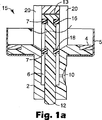
図1aおよび図1bは、例示的なシャトル型の定量分配弁を表す。図1aおよび図1bを参照すると、弁は、典型的には、エーロゾル容器又はバイアル瓶(図示せず)の首に係合し、気密シールを促進する環状シール又はガスケット(4)を有する本体(2)を備える。本体(2)は、エーロゾル容器の首の周りにかしめられる任意の好適な手段(例えば、慣用的な外側ケーシング又はフェルール(5))によって、エーロゾル容器又はバイアル瓶に固定されてもよい。図1bで最もよく分かるように、本体(2)は、例えば、加圧されたエーロゾル配合物を分配するための出口通路(10)を有するチャンバ(6)を画定する。弁棒(12)は、チャンバ(6)を通って延び、閉鎖ないし準備位置(図1aに示される)と分配位置(図1bに示される)との間を移動可能である。弁棒(12)は、望ましくは、弁棒とチャンバ(6)の内壁との間に気密シールを提供する内側シール(16)および外側シール(18)が嵌合される。チャンバ(6)、弁棒(12)の外部寸法、およびシール(16および18)の位置は、チャンバ内(6)でシール(16および18)間に所定の容積が画定されるように配置される。これは、分配位置にある弁を示す、図1bを参照することによって最もよく理解される。図1aで分かるように、その閉鎖ないし準備位置では、弁棒(12)の周りのシール(16および18)間の空間は、エーロゾル配合物を収容する貯蔵器内に延びている。弁棒(12)がその分配位置に下向きに移動する時、シール(18)がチャンバを下に移動し、エーロゾル配合物はチャンバ(6)内に自由に入ることができる。弁棒が更に移動すると、シール(16)はチャンバ(6)に入り、それによって、シール(16および18)とチャンバ(6)の内壁との間に一定容積のエーロゾル配合物が閉じ込められる。弁棒がその分配位置に到達するとき、シール(18)は、出口通路(10)を通過し、それによって一定容積と出口通路(10)との直接連通が可能になり、それによって、一定容積の配合物を分配することができる。図示される弁では、ディスペンサーの容器内に収容されている加圧されたエーロゾル配合物によって発生する蒸気圧によって弁棒がその分配位置の方に外向きに付勢されるように、弁が配置される、特にシール(16および18)の断面積が配置される。シール(16および18)間における弁棒(12)の周りのエーロゾル配合物の(図1aに矢印で表されるような)自由流動を妨げないリブ(20)で弁棒の位置合わせを確実にしてもよい。 1a and 1b represent an exemplary shuttle type metering valve. With reference to FIGS. 1a and 1b, the valve typically engages the neck of an aerosol container or vial (not shown) and has a body (4) with an annular seal or gasket (4) that facilitates a hermetic seal. 2). The body (2) may be secured to the aerosol container or vial by any suitable means (eg, conventional outer casing or ferrule (5)) that is crimped around the neck of the aerosol container. As best seen in FIG. 1b, the body (2) defines a chamber (6) having, for example, an outlet passage (10) for dispensing a pressurized aerosol formulation. The valve stem (12) extends through the chamber (6) and is movable between a closed or ready position (shown in FIG. 1a) and a dispensing position (shown in FIG. 1b). The valve stem (12) is desirably fitted with an inner seal (16) and an outer seal (18) that provide a hermetic seal between the valve stem and the inner wall of the chamber (6). The chamber (6), the external dimensions of the valve stem (12), and the position of the seals (16 and 18) are arranged such that a predetermined volume is defined between the seals (16 and 18) within the chamber (6). The This is best understood by referring to FIG. 1b, showing the valve in the dispensing position. As can be seen in FIG. 1a, in its closed or ready position, the space between the seals (16 and 18) around the valve stem (12) extends into a reservoir containing the aerosol formulation. As the valve stem (12) moves downward to its dispensing position, the seal (18) moves down the chamber and the aerosol formulation is free to enter the chamber (6). As the valve stem moves further, the seal (16) enters the chamber (6), thereby confining a volume of aerosol formulation between the seals (16 and 18) and the inner wall of the chamber (6). When the valve stem reaches its dispensing position, the seal (18) passes through the outlet passage (10), thereby allowing direct communication between the constant volume and the outlet passage (10), thereby providing a constant volume. Can be dispensed. In the illustrated valve, the valve is positioned so that the valve stem is biased outward toward its dispensing position by the vapor pressure generated by the pressurized aerosol formulation contained within the dispenser container. In particular, the cross-sectional area of the seals (16 and 18) is arranged. Ensure the alignment of the valve stem with ribs (20) that do not impede the free flow (as represented by the arrows in FIG. 1a) of the aerosol formulation around the valve stem (12) between the seals (16 and 18). May be.
図1aおよび図1bは、本発明で使用するのに好適な1つの例示的な分配弁を示し、内側の閉鎖ないし準備位置と外側の分配位置との間を移動可能な弁棒を有する他の分配弁、特に、他の定量分配弁も使用するのに好適である。細長い出口部材又は弁棒が外向きに移動すると作動又は噴射する分配弁の他の例は、米国特許第5,772,985号明細書に記載されており、その内容は参照により本明細書に組込まれる。細長い出口部材又は弁棒が移動すると作動又は噴射する分配弁の他の例は、米国特許第2,980,301号明細書、同3,176,887号明細書、同3,176,889号明細書、同3,591,059号明細書、および同4,506,803号明細書に記載されている。 FIGS. 1a and 1b show one exemplary dispensing valve suitable for use with the present invention, and another having a valve stem movable between an inner closed or ready position and an outer dispensing position. Dispensing valves, in particular other metering dispensing valves, are also suitable for use. Another example of a dispensing valve that activates or injects as the elongate outlet member or valve stem moves outward is described in US Pat. No. 5,772,985, the contents of which are hereby incorporated by reference. Incorporated. Other examples of dispensing valves that actuate or inject when the elongate outlet member or valve stem moves are U.S. Pat. Nos. 2,980,301, 3,176,887, and 3,176,889. No. 3,591,059, and No. 4,506,803.
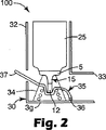
図2は、アダプター(30)の好ましい実施形態を組込んでいる吸入器の形態のディスペンサー(100)の好ましい実施形態の垂直断面図を概略的に示す。アダプターは、内側の閉鎖ないし準備位置と外側の分配位置との間を移動可能な弁棒(12)を備える分配弁(全体を15で示す)を装備したエーロゾル容器(25)を受容するように構成されている細長い又は円筒状の部分(32)を備える。分配弁は、典型的には、弁棒がフェルールを越えて延びている状態で、フェルール(5)によって容器上に嵌合される。アダプターは、また、典型的には、マウスピース部分(33)を備える。容器(25)を、特にフェルール(5)の位置で支持および保持して容器の移動を防止する取付けブロック(34)が提供される。取付けブロック(34)は、望ましくは、分配弁の外側通路(図示せず)がマウスピース部分(33)の軸に沿って位置合わせされるように配置される。アダプターはレバーの形態で提供される作動部材(35)を具備し、これは、ピボット(36)に取付けられ、使用者側の端部(37)を有し、アダプターから、特にアダプターの細長い又は円筒状の部分(32)から外部に延びている。作動部材(35)は、作動部材とアダプターの内部表面との間に取付けられる円錐形の圧縮バネ(39)の作用によって容器(25)の方に上向きに付勢される。弁棒(12)の外端部は、作動部材(35)に当って静止し、この部材は容器の方に上向きに付勢されるため、弁棒は通常、その閉鎖ないし準備位置で静止する。 FIG. 2 schematically shows a vertical cross-sectional view of a preferred embodiment of a dispenser (100) in the form of an inhaler incorporating a preferred embodiment of an adapter (30). The adapter is adapted to receive an aerosol container (25) equipped with a dispensing valve (indicated generally at 15) with a valve stem (12) movable between an inner closed or ready position and an outer dispensing position. It comprises an elongated or cylindrical part (32) that is constructed. The dispensing valve is typically fitted onto the container by the ferrule (5) with the valve stem extending beyond the ferrule. The adapter also typically includes a mouthpiece portion (33). A mounting block (34) is provided that supports and holds the container (25), particularly at the position of the ferrule (5), to prevent movement of the container. The mounting block (34) is desirably arranged so that the outer passage (not shown) of the dispensing valve is aligned along the axis of the mouthpiece portion (33). The adapter comprises an actuating member (35) provided in the form of a lever, which is attached to the pivot (36) and has a user end (37), from the adapter, in particular an elongated or It extends outside from the cylindrical part (32). The actuating member (35) is biased upward toward the container (25) by the action of a conical compression spring (39) mounted between the actuating member and the internal surface of the adapter. The outer end of the valve stem (12) rests against the actuating member (35), which is biased upwardly toward the container, so that the valve stem normally rests in its closed or ready position. .
操作の際、患者は、作動部材(35)の使用者側端部(37)を下向きに押圧し、それと同時にマウスピース部分(33)を通して吸入する。このようにする際、患者は、作動部材(35)をバネ(39)の作用に逆らって下向きに回動させ、それによって弁棒(12)はその分配位置に外向きに移動できる。 In operation, the patient presses the user end (37) of the actuating member (35) downward and simultaneously inhales through the mouthpiece portion (33). In doing so, the patient pivots the actuating member (35) downward against the action of the spring (39), thereby allowing the valve stem (12) to move outwardly to its dispensing position.
望ましくは、分配弁は、弁棒がディスペンサーの容器内に収容されている加圧されたエーロゾル配合物によって発生する蒸気圧によってその分配位置の方に外向きに付勢されるように配置される。従って、弁棒は、内部蒸気圧の影響でその分配位置に外向きに移動する。或いは、分配弁は、その分配位置の方に弁棒を付勢する弁棒の内端部に位置決めされる内部バネの付勢(図示せず)を具備してもよい。この場合、弁棒は、内部バネの付勢の影響でその分配位置に外向きに移動する。 Desirably, the dispensing valve is arranged such that the valve stem is biased outward toward its dispensing position by the vapor pressure generated by the pressurized aerosol formulation contained within the dispenser container. . Therefore, the valve stem moves outward to its distribution position due to the influence of the internal vapor pressure. Alternatively, the dispensing valve may include an internal spring biasing (not shown) positioned at the inner end of the valve stem that biases the valve stem toward its dispensing position. In this case, the valve stem moves outward to its distribution position due to the biasing force of the internal spring.
1回分の用量の薬剤を吸入した後、患者が作動部材(35)を解放するだけで、バネ(39)により作動部材はその静止位置に、従って、弁棒(12)はその閉鎖ないし準備位置に戻ることができる。このリセット作用は、患者が作動部材(35)を解放するとすぐ自動的に起こり、それによって実質上の計量チャンバとしての分配弁の内部部分が空気又は大気中の水分に曝され得る時間が最小限になる。内部バネの付勢を備える分配弁を具備する実施形態では、アダプターのバネは、その外側の分配位置からその閉鎖ないし準備位置に弁棒が戻ることに対応するバネの伸びの範囲で、内部バネによって加えられる圧縮力よりも、好適に更に大きい圧縮力を加えるように選択されることが認識されよう。 After inhaling a single dose of medicament, the patient simply releases the actuating member (35), and the spring (39) brings the actuating member into its rest position, and thus the valve stem (12) is in its closed or ready position. You can return to This reset action occurs automatically as soon as the patient releases the actuating member (35), thereby minimizing the time during which the internal portion of the dispensing valve as a substantially metering chamber can be exposed to air or atmospheric moisture. become. In an embodiment comprising a dispensing valve with an internal spring bias, the spring of the adapter is in the range of spring extension corresponding to the return of the valve stem from its outer dispensing position to its closed or ready position. It will be appreciated that the selection is preferably made to apply a compression force which is preferably greater than the compression force applied by.
図3は、アダプター(30)の別の好ましい実施形態を組込んでいる吸入器の形態のディスペンサー(100)の別の好ましい実施形態の垂直断面図を概略的に示す。図2に表されるディスペンサーと同様に、アダプターは、内側の閉鎖ないし準備位置と外側の分配位置との間を移動可能な弁棒(12)を備える分配弁(全体を15で示す)を装備したエーロゾル容器(25)を受容するように構成されている細長い又は円筒状の部分(32)を備える。アダプターは、また、マウスピース部分(33)、並びに、容器を、特にフェルール(5)の位置で支持および保持して容器の移動を防止する取付けブロック(34)を備える。アダプターは、スライダーの形態の作動部材(35)を具備する。作動部材(35)は、その断面が本質的にC字形であり、細長い又は円筒状の部分(32)と容器(25)との間の間隙内に配置され、使用者側の端部(37)が細長い又は円筒状の部分(32)の開放端から外向きに延び、もう一方の端部、内端部(38)は弁棒を把持する。作動部材の使用者側の端部(37)は、好ましくは、容器の閉鎖端(26)上で延びている凹状の窪みの形態で提供される。作動部材が、容器の方に上向きに付勢され、弁棒(12)が通常、閉鎖ないし準備位置で静止するように、円錐形の圧縮バネ(39)が作動部材(35)の内端部とアダプターの内部表面との間に取付けられる。 FIG. 3 schematically shows a vertical cross-sectional view of another preferred embodiment of a dispenser (100) in the form of an inhaler incorporating another preferred embodiment of an adapter (30). Similar to the dispenser represented in FIG. 2, the adapter is equipped with a dispensing valve (indicated generally at 15) with a valve stem (12) movable between an inner closed or ready position and an outer dispensing position. And an elongated or cylindrical portion (32) configured to receive the aerosol container (25). The adapter also comprises a mouthpiece portion (33) and a mounting block (34) that supports and holds the container, particularly at the position of the ferrule (5), to prevent movement of the container. The adapter comprises an actuating member (35) in the form of a slider. The actuating member (35) is essentially C-shaped in cross section and is disposed in the gap between the elongated or cylindrical portion (32) and the container (25) and has a user end (37). ) Extends outwardly from the open end of the elongated or cylindrical portion (32) and the other end, the inner end (38), grips the valve stem. The user end (37) of the actuating member is preferably provided in the form of a concave depression extending on the closed end (26) of the container. A conical compression spring (39) is provided at the inner end of the actuating member (35) so that the actuating member is biased upwardly toward the container and the valve stem (12) is normally stationary in the closed or ready position. Installed between the adapter and the inner surface of the adapter.
操作の際、患者は、典型的には使用者側の端部の凹状の窪みに指を入れることによって、作動部材(35)の使用者側端部(37)を押し下げ、それと同時にマウスピース部分(33)を通して吸入する。このようにする際、患者は、作動部材(35)をバネ(39)の作用に逆らって下向きに移動させ、それによって弁棒(12)をその分配位置に引く。 During operation, the patient pushes down on the user end (37) of the actuating member (35), typically by placing a finger into a concave depression at the user end, while simultaneously mouthpiece portion. Inhale through (33). In doing so, the patient moves the actuating member (35) downward against the action of the spring (39), thereby pulling the valve stem (12) to its dispensing position.
使用者が押下ないし圧迫力を加えると、弁棒がその分配位置に引かれるような作動機構(以下、「正の引出し作用」と称される)の配置は、分配弁内で内部バネの付勢を必要とすることなく、弁棒(12)を移動させるのに十分な力を提供することが保証されるという点で有利である。従って、医薬エーロゾル配合物中にバネを浸すことに関して起こり得る問題を回避することができる。起こり得るこのような問題には、例えば、バネの大きくて曲がっている表面領域上への薬剤の沈着、薬品とバネとの化学的相互作用、エーロゾル配合物が自由流動してチャンバを出入りすることに対する妨害などが挙げられる。正の引出し作用を具備するこの実施形態および他の(例えば、後述の)実施形態は、中立の付勢を有する分配弁、又は容器内に収容されている加圧されたエーロゾル配合物によって発生する蒸気圧によってのみ弁棒がその分配位置の方に付勢される分配弁と一緒に使用されるのに特に望ましい。 The arrangement of an operating mechanism (hereinafter referred to as "positive pulling action") that causes the valve stem to be pulled to its dispensing position when the user presses or applies a pressing force is provided with an internal spring in the dispensing valve. Advantageously, it is guaranteed to provide sufficient force to move the valve stem (12) without requiring force. Thus, possible problems with dipping the spring in the pharmaceutical aerosol formulation can be avoided. Such problems that may occur include, for example, drug deposition on the large and curved surface area of the spring, chemical interaction between the drug and the spring, and the aerosol formulation free flowing into and out of the chamber. Interference. This and other (eg, described below) embodiments having a positive withdrawal action are generated by a dispensing valve having a neutral bias, or a pressurized aerosol formulation contained within the container. It is particularly desirable for use with a dispensing valve in which the valve stem is biased towards its dispensing position only by vapor pressure.
1回分の用量の薬剤を吸入した後、患者が作動部材(35)を解放するだけで、バネ(39)により作動部材はその静止位置に、従って、弁棒(12)はその閉鎖ないし準備位置に戻ることができる。 After inhaling a single dose of medicament, the patient simply releases the actuating member (35), and the spring (39) brings the actuating member into its rest position, and thus the valve stem (12) is in its closed or ready position. You can return to
図4は、図3に示されるディスペンサー(100)の好ましい実施形態の変形の垂直断面図を概略的に示す。このディスペンサーは、バネ(39)がアダプター(30)上のポスト(40)によって取り付けられているねじりバネの形態であること以外、概ね図3に表されるディスペンサーに類似している。作動部材(35)の使用者側の端部(37)は、アダプター(30)の細長い又は円筒状の部分(32)の上縁部に当って機能する移動止め(41)を更に備える。この止め(41)は、望ましくは、可能な最大の棒移動を制限し、およびそれを画定する。作動部材(35)のもう一方の端部、内端部(38)は、弁棒(12)上に固定配置されている。操作の原理は、図3に示されるディスペンサーと共に記載されているものと類似である。 FIG. 4 schematically shows a vertical cross-sectional view of a variation of the preferred embodiment of the dispenser (100) shown in FIG. This dispenser is generally similar to the dispenser represented in FIG. 3 except that the spring (39) is in the form of a torsion spring attached by a post (40) on the adapter (30). The end (37) on the user side of the actuating member (35) further comprises a detent (41) that functions against the upper edge of the elongated or cylindrical portion (32) of the adapter (30). This stop (41) desirably limits and defines the maximum possible rod movement. The other end and the inner end (38) of the actuating member (35) are fixedly arranged on the valve stem (12). The principle of operation is similar to that described with the dispenser shown in FIG.
図5は、アダプター(30)の追加の好ましい実施形態を組込んでいる吸入器の形態のディスペンサー(100)の追加の好ましい実施形態の垂直断面図を概略的に示す。このディスペンサーは、作動部材(35)が異なる形状を有すること以外、図3に表されるディスペンサーに類似している。特に、作動部材の使用者側の端部(37)は、望ましくは指ボタンの形態であり、アダプターの側壁、特にその細長い又は円筒状の部分(32)から外向きに延びている。更に、延長部(31)もまた、望ましくは指ボタンの形態であり、作動部材(35)の使用者側の端部(37)と協調して使用できるように、アダプターの外部表面の対応する位置に提供される。患者は、作動機構の使用者側の端部(37)と延長部(31)を一緒に圧迫することによって作動機構を操作する。操作の原理は、図3に示されるディスペンサーと共に記載されているものと類似である。 FIG. 5 schematically shows a vertical sectional view of an additional preferred embodiment of a dispenser (100) in the form of an inhaler incorporating an additional preferred embodiment of the adapter (30). This dispenser is similar to the dispenser represented in FIG. 3 except that the actuating member (35) has a different shape. In particular, the user end (37) of the actuating member is preferably in the form of a finger button and extends outwardly from the side wall of the adapter, in particular its elongated or cylindrical part (32). Furthermore, the extension (31) is also preferably in the form of a finger button and corresponds to the external surface of the adapter so that it can be used in concert with the user end (37) of the actuating member (35). Provided in position. The patient operates the actuation mechanism by pressing together the end (37) and extension (31) on the user side of the actuation mechanism. The principle of operation is similar to that described with the dispenser shown in FIG.
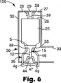
図6は、アダプター(30)の別の好ましい実施形態を組込んでいる吸入器の形態のディスペンサー(100)の別の好ましい実施形態の垂直断面図を概略的に示す。図2〜図5に表される他の実施形態と同様に、アダプター(30)は、内側の閉鎖ないし準備位置と外側の分配位置との間を移動可能な弁棒(12)を備える分配弁(全体を15で示す)を典型的にはフェルール(5)で装備したエーロゾル容器(25)を受容するように構成されている細長い又は円筒状の部分(32)を備える。この実施形態では、アダプターは、弁棒(12)の外端部を保持してアダプターに対する弁棒の移動を防止する係止ブロック(44)を備える。係止ブロック(44)は、望ましくは、分配弁の出口オリフィス(図示せず)がマウスピース部分(33)の軸に沿って位置合わせされるように配置される。アダプターの細長い又は円筒状の部分(32)は、容器(25)の閉鎖した端部(26)上にエンドキャップを具備する。空気が流れるように、オリフィス(28)は、図示されるようにエンドキャップ(27)に、又は或いは、係止ブロック付近のアダプターに提供されてもよい。容器が弁棒の方に下向きにに付勢され、弁棒が通常、その内側の閉鎖ないし準備位置で静止するように、円錐形の圧縮バネ(39)は、エンドキャップ(27)の内部表面と容器の閉鎖した端部(26)の外側表面のと間で案内ポスト(29)に取付けられる。アダプターは、断面が本質的にU字形である作動部材(35)を備える。作動部材のベース部分(47)がアダプターの外部表面に隣接して位置し、側壁又はサイドフィンガー(side fingers)(46)がアダプターの内部に延びるように、作動部材が取り付けられる。側壁又はサイドフィンガー(side fingers)の上縁部(48)は、容器(25)の下側、特にフェルール(5)のショルダー(55)の下側に隣接している。ベース部分(47)は作動部材の使用者側部分の役割をし、望ましくは、凹状の窪み又は親指ボタンの形態である。アダプタ本体の適切なスロット(49)を通して側壁又はサイドフィンガー(46)を挿入することが容易であるように、側壁又はサイドフィンガー(46)は可撓性であってよい。側壁又はサイドフィンガー(46)は、患者がアダプター本体から作動部材(35)を取外すこと又は脱離させることを防止するため、突起(図示せず)を備えてもよい。 FIG. 6 schematically shows a vertical cross-sectional view of another preferred embodiment of a dispenser (100) in the form of an inhaler incorporating another preferred embodiment of an adapter (30). Similar to the other embodiments represented in FIGS. 2-5, the adapter (30) comprises a valve stem (12) that is movable between an inner closed or ready position and an outer dispensing position. An elongate or cylindrical portion (32) configured to receive an aerosol container (25), typically equipped with a ferrule (5) (indicated generally at 15). In this embodiment, the adapter comprises a locking block (44) that holds the outer end of the valve stem (12) and prevents movement of the valve stem relative to the adapter. The locking block (44) is desirably arranged so that the outlet orifice (not shown) of the dispensing valve is aligned along the axis of the mouthpiece portion (33). The elongated or cylindrical portion (32) of the adapter comprises an end cap on the closed end (26) of the container (25). The orifice (28) may be provided on the end cap (27) as shown, or alternatively on the adapter near the locking block, so that air flows. A conical compression spring (39) is provided on the inner surface of the end cap (27) so that the container is biased downward toward the valve stem and the valve stem normally rests in its closed or ready position. And the guide post (29) between the outer surface of the closed end (26) of the container. The adapter comprises an actuating member (35) that is essentially U-shaped in cross section. The actuating member is mounted such that the base portion (47) of the actuating member is located adjacent to the exterior surface of the adapter and the side walls or side fingers (46) extend into the interior of the adapter. The upper edges (48) of the side walls or side fingers are adjacent the lower side of the container (25), in particular the lower side of the shoulder (55) of the ferrule (5). The base portion (47) serves as the user side portion of the actuating member and is preferably in the form of a concave depression or thumb button. The side wall or side finger (46) may be flexible so that it is easy to insert the side wall or side finger (46) through a suitable slot (49) in the adapter body. The side walls or side fingers (46) may be provided with protrusions (not shown) to prevent the patient from removing or detaching the actuating member (35) from the adapter body.
操作の際、患者は、作動部材(35)のベース部分(47)をアダプター本体の方に押圧し、それと同時にマウスピース部分(33)を通して吸入する。このようにする際、患者は、作動部材(35)がバネ(39)の作用に逆らって容器(25)を上向きに押すようにし、それによって弁棒(12)を(相対的な移動で)その分配位置に引く。1回分の用量の薬剤を吸入した後、患者が作動部材(35)のベース部分(47)を解放するだけで、バネ(39)によって容器(25)はその静止位置に、従って、弁棒(12)はその内側の閉鎖ないし準備位置に自動的に戻ることができる。 In operation, the patient presses the base portion (47) of the actuating member (35) towards the adapter body and simultaneously inhales through the mouthpiece portion (33). In doing so, the patient causes the actuating member (35) to push the container (25) upward against the action of the spring (39), thereby pushing the valve stem (12) (with relative movement). Pull to that dispensing position. After inhaling a dose of medication, the patient simply releases the base portion (47) of the actuating member (35), and the spring (39) causes the container (25) to return to its rest position, and thus the valve stem ( 12) can automatically return to its inner closed or ready position.
本発明の特に好ましい実施形態の本開示は、説明をするためだけのものであり、本発明は、その変更、変形、および改善に及ぶことを理解されたい。 It is to be understood that this disclosure of particularly preferred embodiments of the invention is for purposes of illustration only and that the invention extends to modifications, variations, and improvements thereof.
Claims (10)
加圧エーロゾル配合物を収容する容器であって、1回分の用量を分配するために内側の閉鎖ないし準備位置と外側の分配位置との間を移動可能な弁棒を備える定量分配弁を装備した容器と、
前記容器を受容するように構成されるアダプターであって、作動機構を備え、該作動機構は、使用者が押下ないし圧迫力を加えることにより該作動機構を操作したときに、該押下ないし圧迫力によって前記用量を分配するように構成されるとともに、使用者が該作動機構を解放したときに、前記定量分配弁の前記弁棒が前記閉鎖ないし準備位置に自動的に移動するように構成されている、アダプターと、
を具備するディスペンサー。In a dispenser for dispensing multiple doses of pressurized aerosol formulation to a user,
A container containing a pressurized aerosol formulation, equipped with a metering valve with a valve stem movable between an inner closed or preparatory position and an outer dispensing position for dispensing a single dose A container,
An adapter configured to receive the container, comprising an actuating mechanism, the actuating mechanism when the user operates the actuating mechanism by applying a pressing or compressing force. And is configured to automatically move the valve stem of the metering valve to the closed or ready position when a user releases the actuating mechanism. With an adapter,
A dispenser comprising:
(i)エーロゾル配合物を自由流動させて前記チャンバを出入できるようにし、
(ii)前記弁棒の前記外部表面と前記チャンバの前記内部表面との間で、加圧エーロゾル配合物のための閉鎖した一定容積を画定し、
(iii)前記閉鎖した一定容積が前記出口通路と連通して、該一定容積の加圧エーロゾル配合物を分配できるようになるまで、該閉鎖した一定容積の容積を減少させることなく、該閉鎖した一定容積と共に前記チャンバ内を移動する、
請求項7に記載のディスペンサー。 The metering valve further comprises a chamber and an outlet passage, and the valve stem extends into the chamber and is movable relative to the chamber between the closed or ready position and the dispensing position; The valve stem has a shape with an external surface, and the chamber has an internal shape with an internal surface so that a movable constant volume pressurized aerosol formulation can be defined between them. And while moving between the closed or preparatory position and the dispensing position, the valve stems sequentially,
(I) allowing the aerosol formulation to flow freely to enter and exit the chamber;
(Ii) defining a closed constant volume for the pressurized aerosol formulation between the outer surface of the valve stem and the inner surface of the chamber;
(Iii) The closed constant volume is communicated with the outlet passage to allow the constant volume pressurized aerosol formulation to be dispensed without reducing the closed constant volume volume. Moving in the chamber with a constant volume,
The dispenser according to claim 7 .
Applications Claiming Priority (2)
| Application Number | Priority Date | Filing Date | Title |
|---|---|---|---|
| GBGB0221343.7A GB0221343D0 (en) | 2002-09-16 | 2002-09-16 | Aerosol dispensers and adaptors therefor |
| PCT/US2003/025502 WO2004024221A1 (en) | 2002-09-16 | 2003-08-13 | Aerosol dispensers and adaptors therefor |
Publications (3)
| Publication Number | Publication Date |
|---|---|
| JP2006512937A JP2006512937A (en) | 2006-04-20 |
| JP2006512937A5 JP2006512937A5 (en) | 2006-09-28 |
| JP4620463B2 true JP4620463B2 (en) | 2011-01-26 |
Family
ID=9944057
Family Applications (1)
| Application Number | Title | Priority Date | Filing Date |
|---|---|---|---|
| JP2004536030A Expired - Fee Related JP4620463B2 (en) | 2002-09-16 | 2003-08-13 | Aerosol dispenser and adapter used for it |
Country Status (8)
| Country | Link |
|---|---|
| EP (1) | EP1545670B1 (en) |
| JP (1) | JP4620463B2 (en) |
| AT (1) | ATE345154T1 (en) |
| AU (1) | AU2003262671B2 (en) |
| CA (1) | CA2499020A1 (en) |
| DE (1) | DE60309730T2 (en) |
| GB (1) | GB0221343D0 (en) |
| WO (1) | WO2004024221A1 (en) |
Families Citing this family (4)
| Publication number | Priority date | Publication date | Assignee | Title |
|---|---|---|---|---|
| US8881944B2 (en) | 2008-06-30 | 2014-11-11 | S.C. Johnson & Son, Inc. | Overcap for and a method of actuating a volatile material dispenser |
| USD627224S1 (en) | 2009-10-08 | 2010-11-16 | S.C. Johnson & Son, Inc. | Overcap |
| GB201210082D0 (en) * | 2012-06-07 | 2012-07-25 | Consort Medical Plc | Improved syringe |
| DE102013013397A1 (en) | 2013-08-13 | 2015-03-12 | Epinamics Gmbh | Aerosol dispenser for transdermal pharmaceutical compositions |
Family Cites Families (7)
| Publication number | Priority date | Publication date | Assignee | Title |
|---|---|---|---|---|
| US4648393A (en) * | 1984-11-02 | 1987-03-10 | Ackrad Laboratories, Inc. | Breath activated medication spray |
| GB8917775D0 (en) * | 1989-08-03 | 1989-09-20 | Atomic Energy Authority Uk | Aerosol inhaler |
| GB9214819D0 (en) * | 1992-07-13 | 1992-08-26 | Minnesota Mining & Mfg | Valve assemblies |
| FR2732883B1 (en) * | 1995-04-12 | 1997-06-27 | Correggi Raoul | MOISTURIZER FOR PAPER, FABRICS, COTTON, SPONGE OR THE LIKE, WHICH CAN BE ACTUATED BY USING ONLY THE HAND HOLDING THE SAME |
| US5904139A (en) * | 1997-03-28 | 1999-05-18 | Hauser; Stephen G. | Breath coordinated inhaler |
| GB9807232D0 (en) * | 1998-04-03 | 1998-06-03 | Univ Cardiff | Aerosol composition |
| GB9825118D0 (en) * | 1998-11-16 | 1999-01-13 | Minnesota Mining & Mfg | Breath-actuated aerosol dispensers |
-
2002
- 2002-09-16 GB GBGB0221343.7A patent/GB0221343D0/en not_active Ceased
-
2003
- 2003-08-13 EP EP03795609A patent/EP1545670B1/en not_active Expired - Lifetime
- 2003-08-13 WO PCT/US2003/025502 patent/WO2004024221A1/en active IP Right Grant
- 2003-08-13 CA CA002499020A patent/CA2499020A1/en not_active Abandoned
- 2003-08-13 AT AT03795609T patent/ATE345154T1/en not_active IP Right Cessation
- 2003-08-13 AU AU2003262671A patent/AU2003262671B2/en not_active Ceased
- 2003-08-13 JP JP2004536030A patent/JP4620463B2/en not_active Expired - Fee Related
- 2003-08-13 DE DE60309730T patent/DE60309730T2/en not_active Expired - Lifetime
Also Published As
| Publication number | Publication date |
|---|---|
| GB0221343D0 (en) | 2002-10-23 |
| AU2003262671A1 (en) | 2004-04-30 |
| AU2003262671B2 (en) | 2008-02-14 |
| JP2006512937A (en) | 2006-04-20 |
| DE60309730D1 (en) | 2006-12-28 |
| CA2499020A1 (en) | 2004-03-25 |
| EP1545670A1 (en) | 2005-06-29 |
| DE60309730T2 (en) | 2007-09-20 |
| WO2004024221A1 (en) | 2004-03-25 |
| EP1545670B1 (en) | 2006-11-15 |
| ATE345154T1 (en) | 2006-12-15 |
Similar Documents
| Publication | Publication Date | Title |
|---|---|---|
| US5623920A (en) | Valve assemblies | |
| AU2015258110B2 (en) | Nebulizer, indicator device and container | |
| JP3633870B2 (en) | Specified dose inhalation pump | |
| US6581590B1 (en) | Inhalation actuated device | |
| HU226125B1 (en) | Dispensing device mainly for aerosols | |
| US20200297947A1 (en) | Device for inhalation-synchronised dispensing of a fluid product | |
| JPH04215764A (en) | Inhaler | |
| CA2499769A1 (en) | Breath-actuated aerosol dispensers | |
| US7497214B2 (en) | Aerosol dispensers and adaptors therefor | |
| JP2008532675A (en) | Inhaler | |
| JP2008532678A (en) | Inhaler | |
| CN109069766B (en) | Device for dispensing a fluid product in synchronism with inhalation | |
| US7296567B2 (en) | Breath actuated aerosol dispensers | |
| JP4620463B2 (en) | Aerosol dispenser and adapter used for it | |
| JP2008532677A (en) | Inhaler | |
| EP1702639B1 (en) | Apparatus for dispensing metered amount of aerosolized medication | |
| CN111405919B (en) | Device for dispensing a fluid product in synchronism with inhalation | |
| CN111246905B (en) | Device for the synchronized dispensing of a fluid product by suction | |
| JP2008532672A (en) | Inhaler | |
| AU2001250806B2 (en) | An inhalation actuated device | |
| AU2001250806A1 (en) | An inhalation actuated device |
Legal Events
| Date | Code | Title | Description |
|---|---|---|---|
| A521 | Request for written amendment filed |
Free format text: JAPANESE INTERMEDIATE CODE: A523 Effective date: 20060808 |
|
| A621 | Written request for application examination |
Free format text: JAPANESE INTERMEDIATE CODE: A621 Effective date: 20060808 |
|
| A131 | Notification of reasons for refusal |
Free format text: JAPANESE INTERMEDIATE CODE: A131 Effective date: 20090804 |
|
| A601 | Written request for extension of time |
Free format text: JAPANESE INTERMEDIATE CODE: A601 Effective date: 20091102 |
|
| A602 | Written permission of extension of time |
Free format text: JAPANESE INTERMEDIATE CODE: A602 Effective date: 20091110 |
|
| A521 | Request for written amendment filed |
Free format text: JAPANESE INTERMEDIATE CODE: A523 Effective date: 20100204 |
|
| TRDD | Decision of grant or rejection written | ||
| A01 | Written decision to grant a patent or to grant a registration (utility model) |
Free format text: JAPANESE INTERMEDIATE CODE: A01 Effective date: 20100928 |
|
| A01 | Written decision to grant a patent or to grant a registration (utility model) |
Free format text: JAPANESE INTERMEDIATE CODE: A01 |
|
| A61 | First payment of annual fees (during grant procedure) |
Free format text: JAPANESE INTERMEDIATE CODE: A61 Effective date: 20101028 |
|
| FPAY | Renewal fee payment (event date is renewal date of database) |
Free format text: PAYMENT UNTIL: 20131105 Year of fee payment: 3 |
|
| R150 | Certificate of patent or registration of utility model |
Free format text: JAPANESE INTERMEDIATE CODE: R150 |
|
| LAPS | Cancellation because of no payment of annual fees |