JP2008532672A - Inhaler - Google Patents
Inhaler Download PDFInfo
- Publication number
- JP2008532672A JP2008532672A JP2008501407A JP2008501407A JP2008532672A JP 2008532672 A JP2008532672 A JP 2008532672A JP 2008501407 A JP2008501407 A JP 2008501407A JP 2008501407 A JP2008501407 A JP 2008501407A JP 2008532672 A JP2008532672 A JP 2008532672A
- Authority
- JP
- Japan
- Prior art keywords
- canister
- loading
- inhaler
- actuating
- inhaler according
- Prior art date
- Legal status (The legal status is an assumption and is not a legal conclusion. Google has not performed a legal analysis and makes no representation as to the accuracy of the status listed.)
- Pending
Links
Images


Classifications
-
- A—HUMAN NECESSITIES
- A61—MEDICAL OR VETERINARY SCIENCE; HYGIENE
- A61M—DEVICES FOR INTRODUCING MEDIA INTO, OR ONTO, THE BODY; DEVICES FOR TRANSDUCING BODY MEDIA OR FOR TAKING MEDIA FROM THE BODY; DEVICES FOR PRODUCING OR ENDING SLEEP OR STUPOR
- A61M15/00—Inhalators
- A61M15/009—Inhalators using medicine packages with incorporated spraying means, e.g. aerosol cans
-
- A—HUMAN NECESSITIES
- A61—MEDICAL OR VETERINARY SCIENCE; HYGIENE
- A61M—DEVICES FOR INTRODUCING MEDIA INTO, OR ONTO, THE BODY; DEVICES FOR TRANSDUCING BODY MEDIA OR FOR TAKING MEDIA FROM THE BODY; DEVICES FOR PRODUCING OR ENDING SLEEP OR STUPOR
- A61M15/00—Inhalators
- A61M15/0001—Details of inhalators; Constructional features thereof
- A61M15/0021—Mouthpieces therefor
- A61M15/0025—Mouthpieces therefor with caps
-
- B—PERFORMING OPERATIONS; TRANSPORTING
- B05—SPRAYING OR ATOMISING IN GENERAL; APPLYING FLUENT MATERIALS TO SURFACES, IN GENERAL
- B05B—SPRAYING APPARATUS; ATOMISING APPARATUS; NOZZLES
- B05B11/00—Single-unit hand-held apparatus in which flow of contents is produced by the muscular force of the operator at the moment of use
- B05B11/01—Single-unit hand-held apparatus in which flow of contents is produced by the muscular force of the operator at the moment of use characterised by the means producing the flow
- B05B11/10—Pump arrangements for transferring the contents from the container to a pump chamber by a sucking effect and forcing the contents out through the dispensing nozzle
- B05B11/1042—Components or details
- B05B11/1052—Actuation means
- B05B11/1056—Actuation means comprising rotatable or articulated levers
-
- A—HUMAN NECESSITIES
- A61—MEDICAL OR VETERINARY SCIENCE; HYGIENE
- A61M—DEVICES FOR INTRODUCING MEDIA INTO, OR ONTO, THE BODY; DEVICES FOR TRANSDUCING BODY MEDIA OR FOR TAKING MEDIA FROM THE BODY; DEVICES FOR PRODUCING OR ENDING SLEEP OR STUPOR
- A61M15/00—Inhalators
- A61M15/0065—Inhalators with dosage or measuring devices
- A61M15/0068—Indicating or counting the number of dispensed doses or of remaining doses
- A61M15/007—Mechanical counters
-
- A—HUMAN NECESSITIES
- A61—MEDICAL OR VETERINARY SCIENCE; HYGIENE
- A61M—DEVICES FOR INTRODUCING MEDIA INTO, OR ONTO, THE BODY; DEVICES FOR TRANSDUCING BODY MEDIA OR FOR TAKING MEDIA FROM THE BODY; DEVICES FOR PRODUCING OR ENDING SLEEP OR STUPOR
- A61M15/00—Inhalators
- A61M15/08—Inhaling devices inserted into the nose
-
- B—PERFORMING OPERATIONS; TRANSPORTING
- B05—SPRAYING OR ATOMISING IN GENERAL; APPLYING FLUENT MATERIALS TO SURFACES, IN GENERAL
- B05B—SPRAYING APPARATUS; ATOMISING APPARATUS; NOZZLES
- B05B11/00—Single-unit hand-held apparatus in which flow of contents is produced by the muscular force of the operator at the moment of use
- B05B11/0005—Components or details
- B05B11/0037—Containers
- B05B11/0038—Inner container disposed in an outer shell or outer casing
Abstract
医薬を吸入によって送達するための吸入器において、キャニスタ(5)であって、基部および頭部を有し、医薬を収容するチャンバを画成する本体(23)と、前記本体(23)から延びる弁棒(25)とを備え、使用時に前記キャニスタ(5)が作動されると弁棒(25)から医薬が送達される、キャニスタ(5)と、前記キャニスタを受けるハウジング(11)を備える作動装置と、前記キャニスタ(5)を作動させるための作動機構(9)とを備え、該作動機構(9)が、装填部材(61)を備え、該装填部材(61)は、前記キャニスタ(5)内に嵌め込まれ、またはそれに含まれ、装填部分(75)を備え、前記装填部分(75)は、前記キャニスタ(5)の前記本体(23)の前記基部から離隔して配置され、前記装填部材(61)を、第1の休止位置から、医薬を送達するために前記キャニスタ(5)が作動される第2の作動位置へと駆動するように作用し、前記作動機構(9)がさらに、作動部材(63)を備え、該作動部材(63)は、前記キャニスタ(5)の前記本体(23)の前記基部に設けられ、前記装填部材(61)の前記装填部分(75)へと結合され、医薬を送達するよう前記キャニスタ(5)を作動させるために使用者によって動作させることができる、吸入器。
【選択図】図3In an inhaler for delivering medication by inhalation, a canister (5) having a base and a head and defining a chamber for containing the medication, and extending from said body (23) Actuation comprising a canister (5) and a housing (11) for receiving the canister, wherein the canister (5) is actuated when in use and the canister (5) is activated in use And an actuating mechanism (9) for actuating the canister (5), the actuating mechanism (9) comprising a loading member (61), the loading member (61) comprising the canister (5) ) Fitted into or contained therein, comprising a loading portion (75), said loading portion (75) being spaced apart from said base of said body (23) of said canister (5), said loading Member (6 ) From a first rest position to a second actuated position where the canister (5) is actuated to deliver medication, the actuating mechanism (9) further comprising an actuating member (63), the actuating member (63) is provided at the base of the body (23) of the canister (5) and is coupled to the loading portion (75) of the loading member (61), An inhaler that can be actuated by a user to actuate the canister (5) to deliver a medicament.
[Selection] Figure 3
Description
本発明は、吸入によって医薬を投与するための吸入器用の作動装置、およびそれを備える吸入器に関する。本発明は、特に、加圧式定量噴霧式吸入器(pMDI)用の作動装置に関するが、それに限定されない。 The present invention relates to an actuating device for an inhaler for administering a medicine by inhalation and an inhaler comprising the same. The invention particularly relates to, but is not limited to, an actuating device for a pressurized metered dose inhaler (pMDI).
pMDIは、吸入装置業界でよく知られている。したがって、pMDIの構造および動作については、必要最低限以外は説明しなくてよい。 pMDI is well known in the inhaler industry. Therefore, the structure and operation of pMDI need not be described except for the minimum necessary.
pMDIは、キャニスタおよび作動装置ハウジングを備える。ハウジングは、必須ではないが一般に管状であり、一般に、たとえば成形によって、プラスチック材料で製作される。キャニスタは、アルミニウムなど金属で通常製作される、1つの開端部を有するキャニスタを含む。キャニスタの開端部は、計量弁アセンブリによって封止して覆われる。弁アセンブリは、通常、キャニスタの出口または作業端部から突出する、中空の分配部材または弁棒を備える。分配部材は、通常戻しばねである弁アセンブリ内の付勢機構によって分配部材がそこへと付勢される拡張位置と、押下位置との間で、キャニスタに対して相対的に摺動運動するように取り付けられる。 The pMDI includes a canister and an actuator housing. The housing is generally but not necessarily tubular and is generally made of a plastic material, for example by molding. The canister includes a canister having one open end, typically made of a metal such as aluminum. The open end of the canister is sealed and covered by a metering valve assembly. The valve assembly typically comprises a hollow dispensing member or valve stem that projects from the outlet or working end of the canister. The dispensing member is slidably moved relative to the canister between an extended position where the dispensing member is biased thereto by a biasing mechanism in the valve assembly, usually a return spring, and a depressed position. Attached to.
使用に際して、封止されたキャニスタは、加圧された医薬用エアゾール製剤を収容する。製剤は、医薬および流体噴射剤、ならびに、任意で1つまたは複数の賦形剤および補助剤を含む。医薬は通常、製剤中の、溶液または懸濁液中にある。噴射剤は通常、無フロン噴射剤であり、液体噴射剤が適しており、たとえば、HFA−134a、またはHFA−227とすることができる。 In use, the sealed canister contains a pressurized pharmaceutical aerosol formulation. The formulations include pharmaceutical and fluid propellants, and optionally one or more excipients and adjuvants. The medicament is usually in solution or suspension in the formulation. The propellant is usually a chlorofluorocarbon-free propellant, and a liquid propellant is suitable. For example, HFA-134a or HFA-227 can be used.
分配部材が拡張位置から押下位置へと運動することによって、1回の定量投与分のエアゾール製剤が、分配部材を通してキャニスタから分配される。通常、計量弁アセンブリは、規定の体積の計量チャンバを備える。分配部材の拡張位置において、キャニスタの内容物が、分配部材を通して計量チャンバと流体連通させられ、そのため計量チャンバが、エアゾール製剤で満たされる。分配部材が押下されると、計量チャンバは、キャニスタの内部空間から隔離され、分配部材を通して外部環境と流体連通させられる。すなわち、計量チャンバ内の規定の体積のエアゾール製剤が、分配部材を通して外部環境へと分配される。 As the dispensing member moves from the extended position to the depressed position, a single metered dose of aerosol formulation is dispensed from the canister through the dispensing member. Typically, the metering valve assembly comprises a metered chamber of a defined volume. In the extended position of the dispensing member, the contents of the canister are in fluid communication with the metering chamber through the dispensing member so that the metering chamber is filled with the aerosol formulation. When the dispensing member is depressed, the metering chamber is isolated from the interior space of the canister and is in fluid communication with the external environment through the dispensing member. That is, a defined volume of aerosol formulation in the metering chamber is dispensed through the dispensing member to the external environment.
そのような計量弁アセンブリは、当業界でよく知られており、とりわけ、Bespak Plc社(英国、Norfolk、King’s Lynn)、およびValois S.A.S.社(仏国、Le Neubourg)から入手することができる。 Such metering valve assemblies are well known in the art and include, among others, Bespark Plc (Norfolk, King's Lynn, UK), and Valois S., et al. A. S. Available from the company (Le Neubourg, France).
ハウジングは、通常、開端部を有する内部通路を備える。キャニスタは、まずキャニスタを弁アセンブリ内に挿入した状態で、開端部を通して内部通路内へと摺動させることができる。キャニスタが「休止位置」でハウジング内に受けられるときに、キャニスタの分配部材を受けるステムブロックは、分配部材を受けるための入口端部と、出口端部とを備える通路を有し、出口端部は、通常マウスピースまたは鼻用ノズルであるハウジングの分配出口と対面する。ステムブロックは、分配部材を固定して保持し、キャニスタをその休止位置へと、またさらにハウジング内へと「作動位置」まで押すことによって、分配部材が、キャニスタに対して相対的に、拡張位置から押下位置へと動かされる。それによって、1回の定量投与分のエアゾール製剤が、ステムブロックの内部通路を通してハウジングの分配出口から分配される。 The housing typically includes an internal passage having an open end. The canister can be slid into the internal passage through the open end with the canister inserted into the valve assembly. When the canister is received in the housing in the “rest position”, the stem block that receives the distribution member of the canister has a passageway having an inlet end for receiving the distribution member and an outlet end, the outlet end Faces the dispensing outlet of the housing, usually a mouthpiece or nasal nozzle. The stem block holds the dispensing member fixed and pushes the canister into its rest position and further into the housing to the “operating position” so that the dispensing member is in the extended position relative to the canister. Is moved to the pressed position. Thereby, a single metered dose aerosol formulation is dispensed from the dispensing outlet of the housing through the internal passage of the stem block.
使用に際しては、医薬用エアゾール製剤の1回の定量投与を必要とする患者は、分配出口上で吸息すると同時に、キャニスタを休止位置から作動位置へと押下する。患者が生み出す吸気流は、定量投与分の医薬用エアゾール製剤を、患者の気道内へと連行する。したがって、上記のタイプのpMDIは、呼吸協調(breath−coordinated)型吸入器である。 In use, a patient in need of a single metered dose of a pharmaceutical aerosol formulation inhales on the dispensing outlet and simultaneously depresses the canister from the rest position to the operating position. The inspiratory flow produced by the patient entrains a metered dose of a pharmaceutical aerosol formulation into the patient's airway. Thus, the above type of pMDI is a breath-coordinated inhaler.
吸入器は、一般に、吸入器が使用されていないときに分配出口を覆う、ダストキャップを備える。ダストキャップは、適用されると、異物がハウジング内に入ることを防ぐ。これによって、たとえば、そうでなければハウジング内に蓄積することがある塵または埃を、使用者が吸入することが防止される。これは、使用者が、異物の吸入により深刻な刺激が生じることがある喘息または別の呼吸状態を患う場合に、特に重要である。 Inhalers generally include a dust cap that covers the dispensing outlet when the inhaler is not in use. The dust cap, when applied, prevents foreign objects from entering the housing. This prevents the user from inhaling dust or dirt that may otherwise accumulate in the housing, for example. This is particularly important when the user suffers from asthma or another respiratory condition that can cause severe irritation due to inhalation of a foreign body.
pMDIの開発は、作動指示器またはそのための投与計数器を提供することを含んでいる。そのような投与計数器は、Glaxo Group Limited社のPCT特許出願WO−A−9856444、およびWO−A−2004/001664に記載されている。投与計数器は、キャニスタの弁アセンブリ端部上にしっかりと固定されており、また、表示部を備え、表示部は、キャニスタから分配された、またはその中に残っている、医薬用製剤の定量投与回数を示す。患者は、ハウジング内に設けられた窓を通して、投与計数器の表示部を見ることができる。表示部は、共通の軸の周りに回転可能に取り付けられる複数の指示器回転盤とすることができ、各回転盤は、円周上に連続して表示される数字を有する。 The development of pMDI includes providing an activation indicator or a dose counter for it. Such dose counters are described in Glaxo Group Limited's PCT patent applications WO-A-9856444 and WO-A-2004 / 001664. The dosing counter is fixedly secured on the end of the canister valve assembly and includes a display, the display quantifying the pharmaceutical formulation dispensed from or remaining in the canister Shows the number of doses. The patient can see the dose counter display through a window provided in the housing. The display unit can be a plurality of indicator turntables that are rotatably mounted about a common axis, each turntable having a number displayed continuously on the circumference.
医薬の送達を容易にするという目的で、多くの作動装置が開発されており、その例が、米国特許第A−3,272,391号、同第A−3,272,392号、同第A−4,678,106号、同第A−5,899,365号、同第A−6,237,812号、およびWO−A−99/49917に開示されている。 A number of actuators have been developed for the purpose of facilitating drug delivery, examples of which are described in US Pat. Nos. A-3,272,391, A-3,272,392, A-4,678,106, A-5,899,365, A-6,237,812, and WO-A-99 / 49917.
本発明の一目的は、吸入によって医薬を投与するための、吸入器用の改善された作動装置、およびそれを備える吸入器を提供することである。 One object of the present invention is to provide an improved actuating device for an inhaler and an inhaler comprising the same for administering a medicament by inhalation.
本発明は、一態様において、請求項1に記載の、医薬を吸入によって送達するための吸入器を提供する。 The present invention, in one aspect, provides an inhaler for delivering a medicament by inhalation according to claim 1.
好ましくは、装填部材の装填部分は、キャニスタの本体の頭部に配置される。 Preferably, the loading portion of the loading member is disposed on the head of the canister body.
好ましくは、作動機構は、装填部材の装填部分と作動部材とを動作可能に結合させる、駆動部材をさらに備える。 Preferably, the actuation mechanism further comprises a drive member that operably couples the loading portion of the loading member and the actuation member.
より好ましくは、駆動部材は、作動部材の動作時に装填部材の装填部分に係合するよう枢動されるように、枢動式に取り付けられる。 More preferably, the drive member is pivotally mounted such that it is pivoted to engage the loading portion of the loading member during operation of the actuation member.
さらにより好ましくは、装填部材は、キャニスタの本体の基部を覆って配置される。 Even more preferably, the loading member is disposed over the base of the canister body.
一実施形態において、装填部材の装填部分は、実質的に環状の部分を備える。 In one embodiment, the loading portion of the loading member comprises a substantially annular portion.
好ましくは、装填部材は、キャニスタの本体の外周面の周りに嵌るスリーブと、スリーブの一端にあり、キャニスタの本体の基部に係合する端部分と、スリーブの他端にある装填部分とを備える。 Preferably, the loading member comprises a sleeve that fits around the outer peripheral surface of the canister body, an end portion at one end of the sleeve that engages the base of the canister body, and a loading portion at the other end of the sleeve. .
より好ましくは、装填部材のスリーブは、実質的に、キャニスタの本体の頭部へと延びる。 More preferably, the sleeve of the loading member extends substantially to the head of the canister body.
好ましくは、作動部材は、キャニスタの本体の基部を覆って配置されており、装填部材のスリーブの外周面の周りに嵌るスリーブと、スリーブの一方の末端に配置され、駆動部材を枢動させるように駆動部材に係合する作動要素と、スリーブの他端にあり、作動部材を動作させるときに使用者による作用を受ける端部分とを備える。 Preferably, the actuating member is disposed over the base of the body of the canister and is disposed on the outer peripheral surface of the sleeve of the loading member and at one end of the sleeve to pivot the drive member. An actuating element that engages the drive member and an end portion at the other end of the sleeve that is acted upon by the user when operating the actuating member.
一実施形態において、作動部材の作動要素は、フランジ要素を備える。 In one embodiment, the actuating element of the actuating member comprises a flange element.
好ましくは、駆動部材が、キャニスタの対向した側部の間に延び、キャニスタの対向した側部の一方側において枢動式に取り付けられ、作動部材の作動要素が、キャニスタの他方の対向した側面の他方側に配置される。 Preferably, the drive member extends between opposite sides of the canister and is pivotally mounted on one side of the opposite side of the canister, and the actuating element of the actuating member is located on the other opposite side of the canister. Arranged on the other side.
好ましくは、ハウジングは、キャニスタの弁棒を受けるノズルブロックを備える。 Preferably, the housing comprises a nozzle block that receives the canister valve stem.
好ましくは、ハウジングは、出口を備え、使用者はそれを通して吸引する。 Preferably, the housing comprises an outlet through which the user sucks.
より好ましくは、出口はマウスピースである。 More preferably, the outlet is a mouthpiece.
本発明はまた、本発明の吸入器の作動装置にも及ぶ。 The invention also extends to the actuating device of the inhaler of the invention.
本発明のその他の態様および特徴を、添付の特許請求の範囲、ならびに添付の図および図面を参照しながら次に説明する例示的な実施形態において説明する。 Other aspects and features of the present invention are described in the exemplary embodiments described below with reference to the appended claims and the accompanying drawings and drawings.
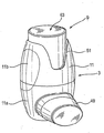
図1から図4は、本発明の第1の実施形態による、手持ちの手動操作可能なpMDIタイプの吸入器を示す。 1 to 4 show a hand-held manually operable pMDI type inhaler according to a first embodiment of the present invention.
吸入器は、主本体3を備える作動装置と、主本体3内に嵌め込まれ、吸入器の作動時に送達される医薬を収容するエアゾールキャニスタ5と、吸入器を作動させるために使用者が動作させることができる作動機構9とを備える。
The inhaler is actuated by the user to operate the actuating device including the
主本体3は、使用時にキャニスタ5が内部に嵌め込まれるハウジング11、および、ハウジング11の下端部と流体連通し使用時に使用者の唇の間に把持される、本実施形態では管状要素であるマウスピース13を備える。マウスピース13は、その代わりに、鼻ノズルとして構成することができる。
The
本実施形態におけるキャニスタ5は、上記で概説したような標準的なタイプのものであり、たとえばHFA噴射剤など加圧された無フロン噴射剤中の医薬を収容する、チャンバを画成する本体23と、本体23の一端部、すなわち頭部から延びる弁棒25と、内部計量弁(図示せず)とを備え、内部計量弁は、通常、内部弁ばね(図示せず)によって閉位置へと付勢されており、弁棒25がキャニスタ本体23内へと押下されると、キャニスタ5から1回の定量投与分の医薬を送達するために開かれる。
The
本実施形態では、ハウジング11は、第1および第2のハウジング部品11a、11bを備え、それらはここではクリップによって互いに取り付けられる。
In this embodiment, the
第1の、下部ハウジング部品11aは、マウスピース13と流体連通し、本実施形態では第1のハウジング部品11aの基底面上に配置された、キャニスタ5の弁棒25を受けるためのノズルブロック31と、支持部材33とを備え、以下でより詳細に説明するように、支持部材33に対して、作動機構9の駆動部材65が枢動式に結合される。本実施形態では、下部ハウジング部品11aは、ここでは成形によって、単一の一体ユニットとして形成される。
The first
図3および図4を特に参照すると、ノズルブロック31は、キャニスタ5の弁棒25を受けるための管状ボア37を備え、ボア37は、本実施形態ではハウジング11の長手軸と同軸である。管状ボア37は、その一方の、すなわち上端部において開き、弁棒25の外側寸法と実質的に同じ内側寸法を有する上方部分39と、より小さい寸法を有する下方部分41とを備え、部分39および41が共になって、弁棒25の末端のための環状座部を画成する。管状ボア37は、その下方部分41内に、噴霧をマウスピース13内へとまたそれを通して送るように構成される、側方に向けられた噴霧オリフィス45をさらに備える。
With particular reference to FIGS. 3 and 4, the
再び図3および図4を特に参照すると、本実施形態では、支持部材33は、枢動部47を備える直立部材であり、枢動部47の周りで、作動機構9の駆動部材65が枢動式に支持される。
3 and 4 in particular, in this embodiment, the
吸入器は、マウスピース13を閉鎖するマウスピースキャップ49をさらに備える。
The inhaler further includes a
第2の上部ハウジング部品11aは、その上端部において開口51を備え、開口51は、以下でより詳細に説明するように作動部材9の動作を可能にする。
The second
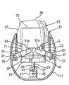
作動機構9は、キャニスタ5の本体23の基部を覆って嵌められる装填部材61と、第2のハウジング部品11b内の開口51のところに配置される作動部材63と、駆動部材65とを備え、駆動部材65は、作動部材63の押下時に、装填部材61、したがってキャニスタ5の本体23を下向きに駆動させるように、装填部材61と作動部材63とを動作可能に結合させる。
The
本実施形態では、装填部材61は、ここでは部分的に管状であり実質的にU字形のスリーブである、スリーブ71を備え、スリーブ71は、キャニスタ5の本体23の外周壁と締り嵌めされ、キャニスタ5の本体23の基部から頭部へと、キャニスタ5の本体23の実質的に全長にわたって延びる。装填部材61はさらに、スリーブ71の一方の、すなわち上端部にある、ここではスリーブ71をまたぎ、キャニスタ5の本体23の基部に係合する端部分73と、スリーブ71の他方の、すなわち下端部にある、ここでは環状フランジである装填部分75とを備え、以下でより詳細に説明するように、駆動部材65が、キャニスタ5を装填するために装填部分75に係合する。
In this embodiment, the loading
本実施形態では、作動部材63は、ここではほぼボタンの形であるキャップ要素であり、ここでは管状スリーブであるスリーブ81を備え、スリーブ81は、装填部材61のスリーブ71の外周壁と締り嵌めされ、作動部材63はさらに、スリーブ81の一方の、すなわち下方末端にある、支持部材33と反対側の(対向した)キャニスタ5の側面に対して、ここではフランジ要素である作動要素83と、スリーブ81の他方の、すなわち上端にあり、スリーブ81の他端を取り囲む端部分85とを備える。
In this embodiment, the actuating
本実施形態では、駆動部材65は、第1の駆動アーム91aおよび第2の駆動アーム91bを備える。駆動アームは、一方の端部において支持部材33上の枢動部47で枢動式に結合され、装填部材61のスリーブ71の対向した側面において、装填部材61の装填部分75に係合するように、装填部材61のスリーブ71の対向した側面の周りに延びる。駆動部材65はさらに、連結要素95を備え、連結要素95は、駆動アーム91a、91bの他方の末端同士を、支持部材33の反対側のキャニスタ5の側面側において相互連結させ、また、作動部材63の作動要素83によって係合されるように配置され、作動部材63が押下されると、駆動アーム91a、91bは、ここでは支持部材33の枢動部47の周りで枢動することによって一斉に駆動され、装填部材61したがってキャニスタ5を、作動させるために下向きに駆動する。
In the present embodiment, the
本実施形態では、駆動アーム91a、91bはそれぞれ、ここでは2つの傾斜面の交点によって画成される駆動点97を備え、点97は実質的に、キャニスタ5がその長手軸に沿ってキャニスタ5の弁棒25を通じて実質的に均一に装填されるように、ハウジング11の長手軸と交差する平面内に配置される。
In this embodiment, each of the
作動装置の動作を、以下で説明する。 The operation of the actuator will be described below.
使用者はまず、図1に示すような作動装置を片手で持ち、マウスピースキャップ49を取り外す。
First, the user holds the operating device as shown in FIG. 1 with one hand and removes the
次いで使用者は、マウスピース13を唇の間にはさみ、吸気と協調させて、作動装置を保持している手の1本または複数本の指で作動機構9の作動部材63を押下することによって、吸入器を作動させる。
Next, the user puts the
図4に示すように、作動部材63の押下によって、作動部材63の作動要素83が、駆動部材65の連結要素95に係合させられ、それによって駆動部材65が、支持部材33上の枢動部47の周りで枢動され、それぞれの駆動アーム91a、91bの枢動点97と装填部材61の装填部分75との係合によって、装填部材61を駆動する。
As shown in FIG. 4, depressing the actuating
装填部材61のこの下向きの運動は、キャニスタ5の本体23を、キャニスタ5の固定弁棒25に対して下向きに駆動し、キャニスタ5を作動させて、弁棒からマウスピース13内へと、またそれを通して分配される、医薬製剤の噴霧を送達する。
This downward movement of the
作動部材63を解放すると、吸入器は、弁の戻しばねによって、図3に示す休止構成へと戻され、次の作動の準備状態となる。
When the actuating
作動後に、吸入器は、口から取り外され、マウスピースキャップ49が、図1に示すようにマウスピースに嵌められ、次の作動の準備状態となる。
After actuation, the inhaler is removed from the mouth and the
図5は、本発明の第2の実施形態による、手持ちの手動操作可能なpMDIタイプの吸入器を示す。 FIG. 5 shows a hand-held manually operable pMDI type inhaler according to a second embodiment of the present invention.
本実施形態の吸入器は、上記で説明した実施形態の吸入器と非常に類似しており、したがって、不必要な説明の重複を避けるために、相違点のみを詳細に説明し、同様の部品を同様の参照符号によって指示する。 The inhaler of this embodiment is very similar to the inhaler of the embodiment described above, and therefore only the differences will be described in detail and similar parts will be avoided in order to avoid unnecessary duplication of explanation. Are indicated by similar reference signs.
本実施形態の吸入器は、ハウジング部品11a、11bが、ねじ式に結合され、支持部材33が、上部ハウジング部品11bに配置されるという点で、上記第1の実施形態と異なる。この構造は、キャニスタ5の迅速な交換をもたらすという点で有利である。
The inhaler according to this embodiment is different from the first embodiment in that the
本実施形態の動作は、上記実施形態の動作と同じである。 The operation of this embodiment is the same as that of the above embodiment.
図6および図7は、本発明の第3の実施形態による、手持ちの手動操作可能なpMDIタイプの吸入器を示す。本実施形態の吸入器は、上記で説明した第1の実施形態の吸入器と非常に類似しており、したがって、不必要な説明の重複を避けるために、相違点のみを詳細に説明し、同様の部品を同様の参照符号によって指示する。 6 and 7 show a hand-held manually operable pMDI type inhaler according to a third embodiment of the present invention. The inhaler of this embodiment is very similar to the inhaler of the first embodiment described above, and therefore only the differences will be described in detail in order to avoid unnecessary description duplication, Similar parts are indicated by similar reference numerals.
本実施形態の吸入器は、以下の顕著な点において第1の実施形態の吸入器と異なる。 The inhaler of the present embodiment differs from the inhaler of the first embodiment in the following salient points.
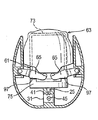
まず、作動機構9は、ハウジング11の対向する内側側部上に、1対の枢動する駆動部材65を備える。各駆動部材65は、第1の実施形態のように、1対の駆動アーム91a、91b(そのうち1つずつのみを示す)を有するが、駆動アーム91a、91bの末端は、本実施形態では互いに連結されない。実際、駆動部材65は、叉骨形の構成であり、叉骨形の先端部分を形成する駆動アーム91a、91bを有する。
First, the
次に、この場合もキャップの形である作動部材63は、作動部材63の末端にある舌部の形である中心に配置された作動要素83を、その各対向した側部上に有する(1つのみを示す)。各作動要素83は、各駆動部材65から1つずつ延びる、1対の駆動アーム91a、91bに係合する。
Next, the actuating
本実施形態の吸入器の動作は、上記で説明した実施形態の動作と同じである。より詳細には、図7に示すように、作動部材63の押下によって、その作動部材83が、駆動部材65を枢動部47の周りで下方向に枢動させる。次いで装填部材61が、それぞれの駆動アーム91a、91bの枢動点97と装填部材61の装填部分75との係合によって、下向きに駆動される。装填部材61のこの下向きの運動は、端部分73とキャニスタ本体23の基部との係合によって、キャニスタ5の本体23をキャニスタ5の固定弁棒25に対して下向きに駆動し、キャニスタ5を作動させて、弁棒からマウスピース13内へと、またそれを通して分配される、医薬製剤の噴霧を送達する。
The operation of the inhaler of this embodiment is the same as that of the embodiment described above. More specifically, as shown in FIG. 7, when the actuating
本発明の図示の実施形態における作動機構は、機械的な利点を有することが理解されるであろう。すなわち、(弁の戻しばねの戻り力に打ち勝つことによって)吸入器を動作させるために、使用者が加える必要がある手の力は、これ以外の場合よりも、たとえば使用者が弁の戻りばねの戻り力に対抗してキャニスタ5の基部上を下方へと押さなければならない標準的なpMDIの動作時などよりも、小さい。第3の実施形態では、2つの対向配置された駆動部材65を使用することにより、第1の実施形態の単一駆動部材に比べて、装填部分75に加えられた装填力がより良好に平衡され分布される。
It will be appreciated that the actuation mechanism in the illustrated embodiment of the invention has mechanical advantages. That is, the hand force that the user needs to apply to operate the inhaler (by overcoming the return force of the valve return spring) is greater than, for example, that the user may This is smaller than the standard pMDI operation or the like that must be pushed down on the base of the
好ましくは、例示的な実施形態の作動装置の部品はすべて、たとえば成形工程によって、プラスチック材料から製作される。 Preferably, all parts of the actuator of the exemplary embodiment are made from a plastic material, for example by a molding process.
図示の実施形態のキャニスタ5は、参照により内容がすべて本明細書に組み込まれるWO−A−9856444およびWO−A−2004/001664に記載されるような、投与計数器を備えることができる。
The
図示の実施形態の、図示しない一修正形態では、装填部材61は、キャニスタ5の頭部に固定的に連結される付属品の形となり、キャニスタ5を下向きに動かすために駆動部材65がその上に作用するための、装填部分75を備える。一例として、付属品は、WO−A−9856444およびWO−A−2004/001664に記載されるような、投与計数器の形をとることができる。そのような投与計数器のハウジングは、装填部分をもたらすように適合させることができる。
In one modification, not shown, of the illustrated embodiment, the loading
図示の実施形態の、図示しない代替修正形態では、駆動部材65のための装填部分を、キャニスタ5の表面によって提供することができる。
In an alternative modification, not shown, of the illustrated embodiment, a loading portion for the
最後に、本発明を、その例示的な実施形態において説明してきたが、添付の特許請求の範囲によって規定されるような本発明の範囲から逸脱することなく、本発明を多くの異なる方法で修正することができることが理解されるであろう。 Finally, while the invention has been described in exemplary embodiments thereof, the invention has been modified in many different ways without departing from the scope of the invention as defined by the appended claims. It will be understood that it can be done.
また、添付の特許請求の範囲において参照符号を付すことに関して、参照符号は、例示目的のためだけに付されるものであり、特許請求される本発明に対するいかなる制限の付与も意図しないことを理解されたい。 Also, with respect to the reference signs in the appended claims, it is understood that the reference numerals are given for illustrative purposes only and are not intended to give any limitation to the claimed invention. I want to be.
Claims (17)
キャニスタ(5)であって、基部および頭部を有し、医薬を収容するチャンバを画成する本体(23)と、前記本体(23)から延びる弁棒(25)とを備え、使用時に前記キャニスタ(5)が作動されると弁棒(25)から医薬が送達される、キャニスタ(5)と、
前記キャニスタを受けるハウジング(11)を備える作動装置と、
前記キャニスタ(5)を作動させるための作動機構(9)とを備え、
前記作動機構(9)が、装填部材(61)を備え、該装填部材(61)は、前記キャニスタ(5)の前記本体(23)内に嵌め込まれ、またはそれに含まれ、かつ、装填部分(75)を備え、該装填部分(75)は、前記キャニスタ(5)の前記本体(23)の前記基部から離隔して配置され、かつ、前記装填部材(61)を、第1の休止位置から、医薬を送達するために前記キャニスタ(5)が作動される第2の作動位置へと駆動するように作用し、前記作動機構(9)がさらに作動部材(63)を備え、該作動部材(63)は、前記キャニスタ(5)の前記本体(23)の前記基部に設けられ、前記装填部材(61)の前記装填部分(75)へと結合され、医薬を送達するよう前記キャニスタ(5)を作動させるために使用者によって動作させることができる、吸入器。 An inhaler for delivering a medicament by inhalation, comprising:
A canister (5) comprising a body (23) having a base and a head and defining a chamber for containing a medicament, and a valve stem (25) extending from said body (23), said A canister (5), wherein a medicament is delivered from the valve stem (25) when the canister (5) is activated;
An actuator comprising a housing (11) for receiving the canister;
An operating mechanism (9) for operating the canister (5),
The actuating mechanism (9) comprises a loading member (61), which is fitted or contained in the body (23) of the canister (5), and a loading part ( 75), the loading portion (75) being spaced apart from the base of the body (23) of the canister (5), and the loading member (61) from a first rest position , Act to drive the canister (5) to a second actuated position to deliver a medicament, the actuating mechanism (9) further comprising an actuating member (63), the actuating member ( 63) is provided at the base of the body (23) of the canister (5) and is coupled to the loading portion (75) of the loading member (61) to deliver a medicament. Moved by the user to operate It can be, inhaler.
Applications Claiming Priority (2)
| Application Number | Priority Date | Filing Date | Title |
|---|---|---|---|
| GBGB0505542.1A GB0505542D0 (en) | 2005-03-17 | 2005-03-17 | Inhalation devices |
| PCT/GB2006/000936 WO2006097728A1 (en) | 2005-03-17 | 2006-03-16 | Inhalation devices |
Publications (2)
| Publication Number | Publication Date |
|---|---|
| JP2008532672A true JP2008532672A (en) | 2008-08-21 |
| JP2008532672A5 JP2008532672A5 (en) | 2009-03-12 |
Family
ID=34531453
Family Applications (1)
| Application Number | Title | Priority Date | Filing Date |
|---|---|---|---|
| JP2008501407A Pending JP2008532672A (en) | 2005-03-17 | 2006-03-16 | Inhaler |
Country Status (5)
| Country | Link |
|---|---|
| US (1) | US20080190419A1 (en) |
| EP (1) | EP1861144A1 (en) |
| JP (1) | JP2008532672A (en) |
| GB (1) | GB0505542D0 (en) |
| WO (1) | WO2006097728A1 (en) |
Families Citing this family (3)
| Publication number | Priority date | Publication date | Assignee | Title |
|---|---|---|---|---|
| GB2479928A (en) * | 2010-04-30 | 2011-11-02 | R5 Pharmaceuticals Ltd | Holder for a drug delivery device |
| GB201417477D0 (en) * | 2014-10-02 | 2014-11-19 | Norton Waterford Ltd | A fluid dispensing apparatus and a method for manufacturing thereof |
| GB2548569A (en) | 2016-03-21 | 2017-09-27 | Univ Cape Town | An assistive device for an inhaler |
Citations (6)
| Publication number | Priority date | Publication date | Assignee | Title |
|---|---|---|---|---|
| EP0414536A2 (en) * | 1989-08-23 | 1991-02-27 | Riker Laboratories, Inc. | Inhaler |
| FR2812826A1 (en) * | 2000-08-11 | 2002-02-15 | Valois Sa | Fluid product atomizer has pump or valve actuated by side lever for use as a nasal spray |
| JP2002526209A (en) * | 1998-09-24 | 2002-08-20 | アストラゼネカ ユーケイ リミテッド | Improved inhaler |
| US20020170928A1 (en) * | 2001-05-15 | 2002-11-21 | Jerry Grychowski | Medicament applicator |
| WO2004012799A2 (en) * | 2002-08-01 | 2004-02-12 | Glaxo Group Limited | A fluid dispensing device |
| JP2004516075A (en) * | 2000-12-19 | 2004-06-03 | アストラゼネカ・アクチエボラーグ | Discharge device |
-
2005
- 2005-03-17 GB GBGB0505542.1A patent/GB0505542D0/en not_active Ceased
-
2006
- 2006-03-16 EP EP06710098A patent/EP1861144A1/en not_active Withdrawn
- 2006-03-16 WO PCT/GB2006/000936 patent/WO2006097728A1/en not_active Application Discontinuation
- 2006-03-16 US US11/908,801 patent/US20080190419A1/en not_active Abandoned
- 2006-03-16 JP JP2008501407A patent/JP2008532672A/en active Pending
Patent Citations (8)
| Publication number | Priority date | Publication date | Assignee | Title |
|---|---|---|---|---|
| EP0414536A2 (en) * | 1989-08-23 | 1991-02-27 | Riker Laboratories, Inc. | Inhaler |
| JPH03170165A (en) * | 1989-08-23 | 1991-07-23 | Riker Lab Inc | Inhalation device |
| JP2002526209A (en) * | 1998-09-24 | 2002-08-20 | アストラゼネカ ユーケイ リミテッド | Improved inhaler |
| FR2812826A1 (en) * | 2000-08-11 | 2002-02-15 | Valois Sa | Fluid product atomizer has pump or valve actuated by side lever for use as a nasal spray |
| JP2004516075A (en) * | 2000-12-19 | 2004-06-03 | アストラゼネカ・アクチエボラーグ | Discharge device |
| US20020170928A1 (en) * | 2001-05-15 | 2002-11-21 | Jerry Grychowski | Medicament applicator |
| WO2004012799A2 (en) * | 2002-08-01 | 2004-02-12 | Glaxo Group Limited | A fluid dispensing device |
| JP2005534392A (en) * | 2002-08-01 | 2005-11-17 | グラクソ グループ リミテッド | Fluid distributor |
Also Published As
| Publication number | Publication date |
|---|---|
| EP1861144A1 (en) | 2007-12-05 |
| GB0505542D0 (en) | 2005-04-27 |
| US20080190419A1 (en) | 2008-08-14 |
| WO2006097728A1 (en) | 2006-09-21 |
Similar Documents
| Publication | Publication Date | Title |
|---|---|---|
| JP2008532675A (en) | Inhaler | |
| JP2008532678A (en) | Inhaler | |
| EP2056908B1 (en) | Drug dispenser | |
| US20060243275A1 (en) | Breath Actuated Inhaler | |
| HU226125B1 (en) | Dispensing device mainly for aerosols | |
| JP2008532677A (en) | Inhaler | |
| JP2008532674A (en) | Inhaler | |
| AU5158500A (en) | Apparatus and method for dispensing metered amount of aerosolized medication | |
| JP2005534392A (en) | Fluid distributor | |
| US11273272B2 (en) | Trigger mechanism for an inhaler | |
| JP2008532672A (en) | Inhaler | |
| EP1702639B1 (en) | Apparatus for dispensing metered amount of aerosolized medication | |
| AU2017324263B2 (en) | Trigger mechanism for an inhaler | |
| JP2008532676A (en) | Inhaler | |
| JP4620463B2 (en) | Aerosol dispenser and adapter used for it |
Legal Events
| Date | Code | Title | Description |
|---|---|---|---|
| A521 | Request for written amendment filed |
Free format text: JAPANESE INTERMEDIATE CODE: A523 Effective date: 20090121 |
|
| A621 | Written request for application examination |
Free format text: JAPANESE INTERMEDIATE CODE: A621 Effective date: 20090121 |
|
| A977 | Report on retrieval |
Free format text: JAPANESE INTERMEDIATE CODE: A971007 Effective date: 20110421 |
|
| A131 | Notification of reasons for refusal |
Free format text: JAPANESE INTERMEDIATE CODE: A131 Effective date: 20110426 |
|
| A02 | Decision of refusal |
Free format text: JAPANESE INTERMEDIATE CODE: A02 Effective date: 20111011 |