JP4619463B2 - Image coding apparatus and method - Google Patents
Image coding apparatus and method Download PDFInfo
- Publication number
- JP4619463B2 JP4619463B2 JP03590097A JP3590097A JP4619463B2 JP 4619463 B2 JP4619463 B2 JP 4619463B2 JP 03590097 A JP03590097 A JP 03590097A JP 3590097 A JP3590097 A JP 3590097A JP 4619463 B2 JP4619463 B2 JP 4619463B2
- Authority
- JP
- Japan
- Prior art keywords
- image
- code amount
- encoding
- quantization
- quantization index
- Prior art date
- Legal status (The legal status is an assumption and is not a legal conclusion. Google has not performed a legal analysis and makes no representation as to the accuracy of the status listed.)
- Expired - Fee Related
Links
Images


Description
【0001】
【発明の属する技術分野】
本発明は、画像符号化装置および方法に関し、特に、復号画像の画質の劣化を防止することができるようにする画像符号化装置および方法に関する。
【0002】
【従来の技術】
例えば、MPEG(Moving Picture Experts Group)方式などに準拠して画像の圧縮、符号化を行う場合において、良好な画質の復号画像を得ることができるようにするためのアルゴリズムの1つとして、TM5(Test Model 5(Test Model Editing Commitee: "Test Model 5", ISO/IEC JTC/SC29/WG11/N0400(Apr.1993)))が知られている。TM5は、3つのステップから構成され、各ステップでは、次のような処理が行われる。
【0003】
[ステップ1]
前回エンコードした同一のピクチャタイプのフレームのコンプレクシティ(Complexity)に基づいて、今回エンコードするフレームの目標符号量を設定する。
[ステップ2]
各ピクチャタイプ別の目標符号量と発生符号量との差分を管理するための仮想バッファのデータ蓄積量をフィードバックし、そのデータ蓄積量に基づいて、実際の発生符号量が、ステップ1で設定された目標符号量に一致(ほぼ一致)するように、次にエンコードするマクロブロックについて、仮の量子化インデックスを設定する。
[ステップ3]
視覚特性、即ち、復号画像の画質が良好になるように、エンコード対象のマクロブロックの複雑さに基づいて、量子化インデックスを最終的に決定する。
【0004】
従って、TM5では、画像の複雑さに対応して変化する変数Pとして、例えば、画像のアクティビティに対応するものを、発生符号量を目標符号量に一致させるための変数Qとして、例えば、仮想バッファのデータ蓄積量から決定された仮の量子化ステップに対応するものを、それぞれ用いることとすると、マクロブロックを量子化するための最終的な量子化インデックスMQUANTは、例えば、次式にしたがって決定される。
【0005】
MQUANT=f(P,Q)
なお、f(P,Q)は、引数PおよびQに対応する値を、所定の範囲内の値に正規化したものを出力する関数である。
【0006】
【発明が解決しようとする課題】
上述したように、TM5では、量子化インデックスプが、画像の複雑さに対応する変数Pと、発生符号量を目標符号量に一致させるための変数Qとから決定され、その量子化インデックスに対応する量子化ステップで量子化が行われる。
【0007】
このため、ある1フレームの画像を構成するマクロブロックの複雑さが同一であっても、発生符号量が目標符号量と一致しなくなった場合に、量子化ステップが変化することがあり、復号画像の画質が劣化する課題があった。
【0008】
即ち、1フレームを構成するマクロブロックの複雑さが同一である場合には、それらのマクロブロックは、すべて同一の量子化ステップで量子化するのが望ましく、この場合に、マクロブロックが、周囲と異なる量子化ステップで量子化されると、復号画像において、量子化ステップを変えて量子化したマクロブロックの部分が目立つようになる。
【0009】
そして、このような、いわばブロック状のノイズは、特に、量子化ステップが小さい値の範囲を変化するときに顕著に現れる。即ち、量子化ステップが比較的大きな値である7や8の範囲を変化する場合、その変化の割合は1/7や1/8程度であるが、量子化ステップが小さな値である3や4の範囲を変化する場合、その変化の割合は1/3や1/4のように大きくなる。従って、複雑さが同じようなマクロブロックの量子化に用いる量子化ステップが小さい範囲を変化すると、大きい量子化ステップで量子化された方のマクロブロックと、小さい量子化ステップで量子化された方のマクロブロックとの画質の差が顕著に現れることになる。
【0010】
また、画像をMPEG符号化などする際には、高次のDCT係数は重要でないとの観点から、DCT係数に対して、その量子化の際に、量子化マトリクスによる重み付け(傾斜付け)がなされる。即ち、高次のDCT係数は、量子化マトリクスにより、低次のものよりも大きな量子化値で量子化される。従って、量子化ステップが、小さい値ではなく、比較的大きな値の範囲を変化する場合であっても、低次のDCT係数よりも大きな量子化値で量子化される高次のDCT係数については、量子化ステップの1段階の変化が、量子化に使われる量子化値に大きな影響を与え、画質が劣化することがあった。
【0011】
そこで、量子化ステップを固定にして、画像を符号化(エンコード)する方法があるが、これでは、複雑な画像が連続した場合に、発生符号量が極端に増大し、VBV(Video Buffering Verifier)バッファがアンダーフローすることになる。
【0012】
本発明は、このような状況に鑑みてなされたものであり、VBVバッファにより課せられる条件を満たしながら、復号画像の画質が劣化しないように、画像の符号化を行うことができるようにするものである。
【0013】
【課題を解決するための手段】
本発明の第1の画像符号化装置は、画像を符号化する画像符号化装置であって、前記画像を固定の量子化ステップで符号化することによって得られるフレーム単位の発生符号量に基づいて、前記画像の各フレームに割り当てる目標符号量を算出する目標符号量算出手段と、前記画像の符号化に伴うフレーム単位の発生符号量を前記目標符号量に一致させるための量子化インデックスの値を、前記発生符号量が前記目標符号量を所定の割合以上上回ったと仮定して、VBVバッファがアンダーフローすると判断される場合に、前記量子化インデックスを、前記画像のフレーム内で可変とする可変モードに設定し、VBVバッファがアンダーフローしないと判断される場合、前記量子化インデックスの値を、前記画像のフレーム内で固定とする固定モードに設定する量子化インデックス設定手段と、前記量子化インデックス設定手段により可変モードに設定された前記量子化インデックスに対応する量子化ステップを用いて、前記画像を符号化する符号化手段とを備える。
本発明の第1の画像符号化方法は、画像を符号化する画像符号化方法であって、前記画像を固定の量子化ステップで符号化することによって得られるフレーム単位の発生符号量に基づいて、前記画像の各フレームに割り当てる目標符号量を算出する目標符号量算出ステップと、前記画像の符号化に伴うフレーム単位の発生符号量を前記目標符号量に一致させるための量子化インデックスの値を、前記発生符号量が前記目標符号量を所定の割合以上上回ったと仮定して、VBVバッファがアンダーフローすると判断される場合に、前記量子化インデックスを、前記画像のフレーム内で可変とする可変モードに設定し、VBVバッファがアンダーフローしないと判断される場合、前記量子化インデックスの値を、前記画像のフレーム内で固定とする固定モードに設定する量子化インデックス設定ステップと、前記量子化インデックス設定ステップにより可変モードに設定された前記量子化インデックスに対応する量子化ステップを用いて、前記画像を符号化する符号化ステップとを含む。
本発明の第2の画像符号化装置は、画像を符号化する画像符号化装置であって、前記画像を固定の量子化ステップで符号化することによって得られるGOP単位の発生符号量に基づいて、前記画像の各GOPに割り当てる目標符号量を算出する目標符号量算出手段と、前記画像の符号化に伴うGOP単位の発生符号量を前記目標符号量に一致させるための量子化インデックスの値を、前記発生符号量が前記目標符号量を所定の割合以上上回ったと仮定して、VBVバッファがアンダーフローすると判断される場合に、前記量子化インデックスの値を、前記画像のフレーム内で可変とする可変モードに設定し、VBVバッファがアンダーフローしないと判断される場合、前記量子化インデックスの値を、前記画像のフレーム内で固定とする固定モードに設定する量子化インデックス設定手段と、前記量子化インデックス設定手段により可変モードに設定された前記量子化インデックスに対応する量子化ステップを用いて、前記画像を符号化する符号化手段とを備える。
本発明の第2の画像符号化方法は、画像を符号化する画像符号化方法であって、前記画像を固定の量子化ステップで符号化することによって得られるGOP単位の発生符号量に基づいて、前記画像の各GOPに割り当てる目標符号量を算出する目標符号量算出ステップと、前記画像の符号化に伴うGOP単位の発生符号量を前記目標符号量に一致させるための量子化インデックスの値を、前記発生符号量が前記目標符号量を所定の割合以上上回ったと仮定して、VBVバッファがアンダーフローすると判断される場合に、前記量子化インデックスの値を、前記画像のフレーム内で可変とする可変モードに設定し、VBVバッファがアンダーフローしないと判断される場合、前記量子化インデックスの値を、前記画像のフレーム内で固定とする固定モードに設定する量子化インデックス設定ステップと、前記量子化インデックス設定ステップにより可変モードに設定された前記量子化インデックスに対応する量子化ステップを用いて、前記画像を符号化する符号化ステップとを含む。
【0014】
本発明の第3の画像符号化装置は、画像を符号化する画像符号化装置であって、前記画像を固定の量子化ステップで符号化することによって得られるフレーム単位の発生符号量を符号化難易度として算出する符号化難易度算出手段と、前記符号化難易度算出手段により算出された前記符号化難易度に基づいて、前記画像の各フレームに割り当てる目標符号量を算出する目標符号量算出手段と、前記画像の符号化に伴うフレーム単位の発生符号量を前記目標符号量に一致させるための量子化インデックスの値を、前記発生符号量が前記目標符号量を所定の割合以上上回ったと仮定して、VBVバッファがアンダーフローすると判断される場合に、前記量子化インデックスの値を、前記画像のフレーム内で可変とする可変モードに設定し、VBVバッファがアンダーフローしないと判断される場合、前記量子化インデックスの値を、前記画像のフレーム内で固定とする固定モードに設定する量子化インデックス設定手段と、前記量子化インデックス設定手段により可変モードに設定された前記量子化インデックスに対応する量子化ステップを用いて、前記画像を符号化する符号化手段と、を備える画像符号化装置。
本発明の第3の符号化方法は、画像を符号化する画像符号化方法であって、前記画像を固定の量子化ステップで符号化することによって得られるフレーム単位の発生符号量を符号化難易度として算出する符号化難易度算出ステップと、前記符号化難易度算出ステップにより算出された前記符号化難易度に基づいて、前記画像の各フレームに割り当てる目標符号量を算出する目標符号量算出ステップと、前記画像の符号化に伴うフレーム単位の発生符号量を前記目標符号量に一致させるための量子化インデックスの値を、前記発生符号量が前記目標符号量を所定の割合以上上回ったと仮定して、VBVバッファがアンダーフローすると判断される場合に、前記量子化インデックスの値を、前記画像のフレーム内で可変とする可変モードに設定し、VBVバッファがアンダーフローしないと判断される場合、前記量子化インデックスの値を、前記画像のフレーム内で固定とする固定モードに設定する量子化インデックス設定ステップと、前記量子化インデックス設定ステップにより可変モードに設定された前記量子化インデックスに対応する量子化ステップを用いて、前記画像を符号化する符号化ステップとを含む画像符号化方法。
本発明の第4の画像符号化装置は、画像を符号化する画像符号化装置であって、前記画像を固定の量子化ステップで符号化することによって得られるGOP単位の発生符号量を符号化難易度として算出する符号化難易度算出手段と、前記符号化難易度算出手段により算出された前記符号化難易度に基づいて、前記画像の各GOPに割り当てる目標符号量を算出する目標符号量算出手段と、前記画像の符号化に伴うGOP単位の発生符号量を前記目標符号量に一致させるための量子化インデックスの値を、前記発生符号量が前記目標符号量を所定の割合以上上回ったと仮定して、VBVバッファがアンダーフローすると判断される場合に、前記量子化インデックスの値を、前記画像のフレーム内で可変とする可変モードに設定し、VBVバッファがアンダーフローしないと判断される場合、前記量子化インデックスの値を、前記画像のフレーム内で固定とする固定モードに設定する量子化インデックス設定手段と、前記量子化インデックス設定手段により可変モードに設定された前記量子化インデックスに対応する量子化ステップを用いて、前記画像を符号化する符号化手段と、を備える。
本発明の第4の画像符号化方法は、画像を符号化する画像符号化方法であって、前記画像を固定の量子化ステップで符号化することによって得られるGOP単位の発生符号量を符号化難易度として算出する符号化難易度算出ステップと、前記符号化難易度算出ステップにより算出された前記符号化難易度に基づいて、前記画像の各GOPに割り当てる目標符号量を算出する目標符号量算出ステップと、前記画像の符号化に伴うGOP単位の発生符号量を前記目標符号量に一致させるための量子化インデックスの値を、前記発生符号量が前記目標符号量を所定の割合以上上回ったと仮定して、VBVバッファがアンダーフローすると判断される場合に、前記量子化インデックスの値を、前記画像のフレーム内で可変とする可変モードに設定し、VBVバッファがアンダーフローしないと判断される場合、前記量子化インデックスの値を、前記画像のフレーム内で固定とする固定モードに設定する量子化インデックス設定ステップと、前記量子化インデックス設定ステップにより可変モードに設定された前記量子化インデックスに対応する量子化ステップを用いて、前記画像を符号化する符号化ステップとを含む。
【0015】
本発明の第5の画像符号化装置は、画像を符号化する画像符号化装置であって、前記画像を所定ブロック単位で符号化する際の量子化インデックスの値を、発生符号量が目標符号量を所定の割合以上上回ったと仮定して、VBVバッファがアンダーフローすると判断される場合に、前記量子化インデックスの値を、前記画像のフレーム内で可変とする可変モードに設定し、VBVバッファがアンダーフローしないと判断される場合、前記量子化インデックスの値を、前記画像のフレーム内で固定とする固定モードに設定する量子化インデックス設定手段と、前記量子化インデックス設定手段により可変モードに設定された前記量子化インデックスに対応する量子化ステップを用いて、前記画像を符号化する符号化手段とを備える。
本発明の第5の画像符号化方法は、画像を符号化する画像符号化方法であって、前記画像を所定ブロック単位で符号化する際の量子化インデックスの値を、発生符号量が目標符号量を所定の割合以上上回ったと仮定して、VBVバッファがアンダーフローすると判断される場合に、前記量子化インデックスの値を、前記画像のフレーム内で可変とする可変モードに設定し、VBVバッファがアンダーフローしないと判断される場合、前記量子化インデックスの値を、前記画像のフレーム内で固定とする固定モードに設定する量子化インデックス設定ステップと、前記量子化インデックス設定ステップにより可変モードに設定された前記量子化インデックスに対応する量子化ステップを用いて、前記画像を符号化する符号化ステップとを含む。
本発明の第6の画像符号化装置は、画像を符号化する画像符号化装置であって、前記画像を所定ブロック単位で符号化する際の量子化インデックスの値を、発生符号量が目標符号量を所定の割合以上上回ったと仮定して、VBVバッファがアンダーフローすると判断される場合に、前記量子化インデックスの値を、前記画像のフレーム内で可変とする可変モードに設定し、VBVバッファがアンダーフローしないと判断される場合、前記量子化インデックスの値を、前記画像のフレーム内で固定とする固定モードに設定する量子化インデックス設定手段と、前記量子化インデックス設定手段により可変モードに設定された前記量子化インデックスに対応する量子化ステップを用いて、前記画像を量子化する量子化手段とを備える。
本発明の第6の画像符号化方法は、画像を符号化する画像符号化方法であって、前記画像を所定ブロック単位で符号化する際の量子化インデックスの値を、発生符号量が目標符号量を所定の割合以上上回ったと仮定して、VBVバッファがアンダーフローすると判断される場合に、前記量子化インデックスの値を、前記画像のフレーム内で可変とする可変モードに設定し、VBVバッファがアンダーフローしないと判断される場合、前記量子化インデックスの値を、前記画像のフレーム内で固定とする固定モードに設定する量子化インデックス設定ステップと、前記量子化インデックス設定ステップにより可変モードに設定された前記量子化インデックスに対応する量子化ステップを用いて、前記画像を量子化する量子化ステップとを含む。
【0016】
本発明の第1の画像符号化装置および方法においては、画像を固定の量子化ステップで符号化することによって得られるフレーム単位の発生符号量に基づいて、画像の各フレームに割り当てる目標符号量が算出され、画像の符号化に伴うフレーム単位の発生符号量を目標符号量に一致させるための量子化インデックスの値が、発生符号量が目標符号量を所定の割合以上上回ったと仮定されて、VBVバッファがアンダーフローすると判断される場合に、量子化インデックスの値が、画像のフレーム内で可変とする可変モードに設定され、VBVバッファがアンダーフローしないと判断される場合、量子化インデックスの値が、画像のフレーム内で固定とする固定モードに設定され、可変モードに設定された量子化インデックスに対応する量子化ステップが用いられて、画像が符号化される。
本発明の第2の画像符号化装置および方法においては、画像を固定の量子化ステップで符号化することによって得られるGOP単位の発生符号量に基づいて、画像の各GOPに割り当てる目標符号量が算出され、画像の符号化に伴うGOP単位の発生符号量を目標符号量に一致させるための量子化インデックスの値が、発生符号量が目標符号量を所定の割合以上上回ったと仮定されて、VBVバッファがアンダーフローすると判断される場合に、量子化インデックスの値が、画像のフレーム内で可変とする可変モードに設定され、VBVバッファがアンダーフローしないと判断される場合、量子化インデックスの値が、画像のフレーム内で固定とする固定モードに設定され、可変モードに設定された量子化インデックスに対応する量子化ステップが用いられて、画像が符号化される。
【0018】
本発明の第3の画像符号化装置および方法においては、画像を固定の量子化ステップで符号化することによって得られるフレーム単位の発生符号量が符号化難易度として算出され、算出され符号化難易度に基づいて、画像の各フレームに割り当てる目標符号量が算出され、画像の符号化に伴うフレーム単位の発生符号量を目標符号量に一致させるための量子化インデックスの値が、発生符号量が目標符号量を所定の割合以上上回ったと仮定されて、VBVバッファがアンダーフローすると判断される場合に、量子化インデックスの値が、画像のフレーム内で可変とする可変モードに設定され、VBVバッファがアンダーフローしないと判断される場合、量子化インデックスの値が、画像のフレーム内で固定とする固定モードに設定され、可変モードに設定された量子化インデックスに対応する量子化ステップが用いられて、画像が符号化される。
本発明の第4の画像符号化装置および方法においては、画像を固定の量子化ステップで符号化することによって得られるGOP単位の発生符号量が符号化難易度として算出され、算出され符号化難易度に基づいて、画像の各GOPに割り当てる目標符号量が算出され、画像の符号化に伴うGOP単位の発生符号量を目標符号量に一致させるための量子化インデックスの値が、発生符号量が目標符号量を所定の割合以上上回ったと仮定されて、VBVバッファがアンダーフローすると判断される場合に、量子化インデックスの値が、画像のフレーム内で可変とする可変モードに設定され、VBVバッファがアンダーフローしないと判断される場合、量子化インデックスの値が、画像のフレーム内で固定とする固定モードに設定され、可変モードに設定された量子化インデックスに対応する量子化ステップが用いられて、画像が符号化される。
【0019】
本発明の第5の画像符号化装置および方法においては、画像を所定ブロック単位で符号化する際の量子化インデックスの値が、発生符号量が目標符号量を所定の割合以上上回ったと仮定されて、VBVバッファがアンダーフローすると判断される場合に、量子化インデックスが、画像のフレーム内で可変とする可変モードに設定され、VBVバッファがアンダーフローしないと判断される場合、量子化インデックスの値が、画像のフレーム内で固定とする固定モードに設定され、可変モードに設定された量子化インデックスに対応する量子化ステップが用いられ、画像が符号化される。
本発明の第6の画像符号化装置および方法においては、画像を所定ブロック単位で符号化する際の量子化インデックスの値が、発生符号量が目標符号量を所定の割合以上上回ったと仮定されて、VBVバッファがアンダーフローすると判断される場合に、量子化インデックスの値が、画像のフレーム内で可変とする可変モードに設定され、VBVバッファがアンダーフローしないと判断される場合、量子化インデックスの値が、画像のフレーム内で固定とする固定モードに設定され、可変モードに設定された量子化インデックスに対応する量子化ステップが用いられて、画像が符号化される。
【0022】
【発明の実施の形態】
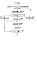
図1は、本発明の画像符号化装置の一実施の形態の構成を示している。
【0023】
この画像符号化装置は、いわゆる2パスエンコーディングによって、画像をMPEG方式などにより可変レートで符号化するようになっており、例えば、DVD(Digigal Versatile Disc)や、ビデオCD(Compact Disc)などのオーサリングシステムその他に適用することができるようになっている。
【0024】
符号化すべき画像データは、エンコーダ1に入力されるようになされおり、エンコーダ1は、画像データを、少なくともDCT係数などの直交変換係数に直交変換し、その直交変換係数を量子化することにより符号化するようになされている。
【0025】
即ち、1パス目では、エンコーダ1は、画像データを、固定の量子化ステップで量子化することにより符号化し、その結果得られる符号化データの発生符号量(あるいは、発生符号量に対応する情報としての、例えば、画像データの符号化難易度(difficulty)など)を、外部コンピュータ2に出力する。外部コンピュータ2は、エンコーダ1からの発生符号量に基づいて、例えば、1GOP(Group Of Picture)や1画面(1フレームまたは1フィールド)ごとの目標符号量を設定する。
【0026】
そして、2パス目では、外部コンピュータ2は、設定した目標符号量を、エンコーダ1に供給し、エンコーダ1は、この目標符号量に、発生符号量が一致するように量子化ステップを設定しながら、画像データの符号化を行う。なお、量子化ステップは、目標符号量の他、過去の発生符号量や、VBVバッファにおけるデータの蓄積量、画像の複雑さなどにも基づいて設定される。
【0027】
2パス目の符号化によって得られた符号化データは、例えば、光ディスクや、光磁気ディスク、磁気テープその他でなる記録媒体3に記録され、あるいは、例えば、地上波、衛星回線、CATV網、インターネットその他でなる伝送路4を介して伝送される。
【0028】
次に、図2は、図1のエンコーダ1の構成例を示している。
【0029】
図2では、エンコーダ1において、画像がMPEG符号化されるようになされている。
【0030】
即ち、符号化すべき画像データは、画像並び替え回路11に供給される。画像並び替え回路11は、入力された画像データのフレーム(またはフィールド)の並びを、必要に応じて替えて、走査変換/マクロブロック化回路12に出力する。即ち、各フレームの画像データは、Iピクチャ、Pピクチャ、またはBピクチャのうちのいずれかとして処理されるが、例えば、Bピクチャの処理に、それより時間的に後のIピクチャやPピクチャが必要な場合があり、このようなIピクチャやPピクチャは、Bピクチャより先に処理する必要がある。そこで、画像並び替え回路11では、時間的に後のフレームを先に処理することができるように、フレームの並びを替えるようになされている。
【0031】
なお、シーケンシャルに入力される各フレームの画像を、I,P,Bピクチャのいずれのピクチャとして処理するかは、予め定められている。
【0032】
画像並び替え回路11において並び替えられた画像データは、走査変換/マクロブロック化回路12に出力され、そこでは、画像データの走査変換およびマクロブロック化が行われ、その結果得られるマクロブロックが、演算器13、動き検出回路23、およびアクティビティ検出回路24に出力される。
【0033】
動きベクトル検出回路23は、走査変換/マクロブロック化回路12から供給されるマクロブロックの動きベクトルを検出する。
【0034】
即ち、動きベクトル検出回路23は、予め定められた所定の参照フレームを参照し、その参照フレームと、走査変換/マクロブロック化回路12からのマクロブロックとをパターンマッチング(ブロックマッチング)することにより、そのマクロブロックの動きベクトルを検出する。
【0035】
ここで、MPEGにおいては、画像の予測モードには、イントラ符号化(フレーム内符号化)、前方予測符号化、後方予測符号化、両方向予測符号化(前方、後方、および両方向の3つの予測符号化は、イントラ符号化に対して、インター符号化と呼ばれる)の4種類があり、Iピクチャはイントラ符号化され、Pピクチャはイントラ符号化または前方予測符号化され、Bピクチャはイントラ符号化、前方予測符号化、後方予測符号化、または両方向予測符号化される。
【0036】
即ち、動きベクトル検出回路23は、Iピクチャについては、予測モードとしてイントラ符号化モードを設定する。この場合、動きベクトル検出回路23では、動きベクトルの検出は行われない。
【0037】
また、動きベクトル検出回路23は、Pピクチャについては、前方予測を行い、その動きベクトルを検出する。さらに、動きベクトル検出回路23は、前方予測を行うことにより生じる予測誤差と、符号化対象のマクロブロック(Pピクチャのマクロブロック)の、例えば分散とを比較し、マクロブロックの分散の方が予測誤差より小さい場合、予測モードとしてイントラ符号化モードを設定する。また、動きベクトル検出回路23は、前方予測を行うことにより生じる予測誤差の方が小さければ、予測モードとして前方予測符号化モードを設定し、検出した動きベクトルを、動き補償回路22に出力する。
【0038】
さらに、動きベクトル検出回路23は、Bピクチャについては、前方予測、後方予測、および両方向予測を行い、それぞれの動きベクトルを検出する。そして、動きベクトル検出回路23は、前方予測、後方予測、および両方向予測についての予測誤差の中の最小のもの(以下、適宜、最小予測誤差という)を検出し、その最小予測誤差と、符号化対象のマクロブロック(Bピクチャのマクロブロック)の、例えば分散とを比較する。その比較の結果、マクロブロックの分散の方が最小予測誤差より小さい場合、動きベクトル検出回路23は、予測モードとしてイントラ符号化モードを設定する。また、動きベクトル検出回路23は、最小予測誤差の方が小さければ、予測モードとして、その最小予測誤差が得られた予測モードを設定し、対応する動きベクトルを、動き補償回路22に出力する。
【0039】
動き補償回路22は、動きベクトルを受信すると、その動きベクトルにしたがって、フレームメモリ21に記憶されている、符号化され、既に局所復号化された画像データを読み出し、これを、予測画像として、演算器13および20に供給する。
【0040】
演算器13は、走査変換/マクロブロック化回路12からのマクロブロックと、動き補償回路22からの予測画像との差分を演算する。この差分値は、DCT回路14(直交変換手段)に供給される。
【0041】
なお、動きベクトル検出回路23において、予測モードとしてイントラ符号化モードが設定された場合、動き補償回路22は、予測画像を出力しない。この場合、演算器13(演算器20も同様)は、特に処理を行わず、走査変換/マクロブロック化回路12からのマクロブロックを、そのままDCT回路14に出力する。
【0042】
DCT回路14では、演算器13の出力に対して、DCT処理が施され、その結果得られるDCT係数が、量子化回路15(量子化手段)に供給される。量子化回路15では、量子化インデックス決定回路25(設定手段)からの量子化インデックスに対応する量子化ステップ(量子化スケール)が設定され、その量子化ステップに量子化マトリクスの係数をかけたものなどで、DCT回路14からのDCT係数が量子化される。この量子化されたDCT係数(以下、適宜、量子化値という)は、VLC器16に供給される。
【0043】
VLC器16では、量子化回路15より供給される量子化値が、例えばハフマン符号などの可変長符号に変換され、バッファ17に出力される。バッファ17は、VLC器16からのデータを一時蓄積し、そのデータ量を平滑化して出力する。なお、バッファ17におけるデータ蓄積量は、発生符号量として、外部コンピュータ2(図1)と量子化インデックス決定回路25に供給されるようになされている。
【0044】
一方、量子化回路15が出力する量子化値は、VLC器16だけでなく、逆量子化回路18にも供給されるようになされている。逆量子化回路18では、量子化回路15からの量子化値が、量子化回路15で用いられた量子化ステップにしたがって逆量子化され、これによりDCT係数に変換される。このDCT係数は、逆DCT回路19に供給される。逆DCT回路19では、DCT係数が逆DCT処理され、演算器20に供給される。
【0045】
演算器20には、逆DCT回路19の出力の他、上述したように、動き補償回路22から、演算器13に供給されている予測画像と同一のデータが供給されており、演算器20は、逆DCT回路19からの信号(予測残差)と、動き補償回路22からの予測画像とを加算することで、元の画像を、局所復号する(但し、予測モードがイントラ符号化である場合には、逆DCT回路19の出力は、演算器20をスルーして、フレームメモリ21に供給される)。なお、この復号画像は、受信側において得られる復号画像と同一のものである。
【0046】
演算器20において得られた復号画像(局所復号画像)は、フレームメモリ21に供給されて記憶され、その後、インター符号化(前方予測符号化、後方予測符号化、または両方向予測符号化)される画像に対する参照画像(参照フレーム)として用いられる。
【0047】
一方、アクティビティ検出回路24では、マクロブロックの複雑さを表す指標として、例えば、そのアクティビティ(activity)が検出され、量子化インデックス決定回路25に供給される。量子化インデックス決定回路25には、外部コンピュータ2から目標符号量が、バッファ17から発生符号量が、アクティビティ検出回路24からアクティビティが、それぞれ供給されるようになされている。そして、量子化インデックス決定回路25は、これらの目標符号量、発生符号量、およびアクティビティに基づいて、量子化インデックスを決定し、量子化回路15に供給する。量子化インデックスは、量子化ステップと1対1に対応するもので、量子化回路15では、上述したように、量子化インデックス決定回路25からの量子化インデックスに対応する量子化ステップで、量子化が行われる。
【0048】
なお、量子化インデックス決定回路25は、1パス目は、固定の量子化インデックスを出力するようになされており、これにより、量子化回路15では、固定の量子化ステップで量子化が行われる。そして、2パス目において、量子化インデックス決定回路25は、バッファ17からの発生符号量、アクティビティ検出回路24からのアクティビティ、さらには、外部コンピュータ2からの目標符号量に基づいて、適応的に量子化インデックスを設定し、これにより、量子化回路15では、そのように適応的に設定された量子化インデックスに対応する量子化ステップで量子化が行われる。
【0049】
次に、2パス目において行われる、量子化インデックス決定回路25における量子化インデックスの設定処理および量子化回路15における量子化処理について、図3および図4のフローチャートを参照して説明する。
【0050】
量子化インデックス決定回路25では、まず最初に、ステップS1において、量子化インデックス(仮の量子化インデックスQ_index)の初期値が設定される。即ち、ステップS1では、Iピクチャ、Pピクチャ、Bピクチャの量子化インデックスQI,QP,QBの初期値として、例えば、9,9,11などがそれぞれ設定される。さらに、ステップS1では、目標符号量と発生符号量との間の誤差の累積値を保持しておくための変数Sum_Eと、符号化した画像のフレーム数をカウントするための変数jとが、例えば0に初期化される。
【0051】
そして、外部コンピュータ2から、第jフレームをエンコードするときの目標符号量Tjが供給されると、量子化インデックス決定回路25では、ステップS2において、その目標符号量Tjが受信され、ステップS3に進み、いま符号化対象となっているフレームのピクチャタイプが判定される。ステップS3において、符号化対象のフレームのピクチャタイプが、Iピクチャ、Pピクチャ、またはBピクチャであると判定された場合、それぞれステップS4,S5、またはS6に進み、第jフレームの画像の発生符号量を目標符号量Tjに一致させるための第1の変数(量子化インデックス)としてのQ_indexに、QI,QP、またはQBが設定され、ステップS7に進む。
【0052】
ステップS7では、マクロブロックを量子化する量子化インデックスMQUANTが決定される。即ち、量子化インデックス決定回路25は、発生符号量を目標符号量Tjに一致させるための第1の変数Q_indexと、符号化対象のマクロブロックの複雑さに対応する第2の変数としての、アクティビティ検出回路24からのアクティビティACTに基づいて、符号化対象のマクロブロックの量子化インデックスMQUANTを設定し、量子化回路15に出力する。量子化回路15では、量子化インデックス決定回路25からの量子化インデックスMQUANTに対応する値が、符号化対象のマクロブロックを量子化するのに用いる量子化ステップとして設定される。
【0053】
量子化ステップが設定されると、ステップS7からS8に進み、量子化回路15において、その量子化ステップで、符号化対象のマクロブロックが量子化され、ステップS9に進む。ステップS9では、1フレーム、即ち、第jフレームを構成するマクロブロックすべての量子化が終了したかどうかが判定され、終了していないと判定された場合、ステップS7に戻り、以下、同様の処理が繰り返される。
【0054】
即ち、マクロブロックごとの量子化インデックスMQUANTは、Q_indexとマクロブロックのアクティビティACTとによって決定されるが、Q_indexは、1フレームを構成するマクロブロックについては同一の値が用いられる。このように、Q_indexは、1フレームの符号化中は固定値とされるため、1フレームの符号化に用いられるマクロブロックごとの量子化インデックスMQUANTは、符号化対象のマクロブロックのアクティビティACTによってのみ変化する。つまり、ここでは、マクロブロックごとの量子化インデックスMQUANTは、1フレームの符号化中においては、例えば、TM5のステップ3における場合のように、画像の複雑さに対応して変化するが、例えば、TM5のステップ2における場合のように、レートコントロール(発生符号量を目標符号量に一致させる制御)のためには変化しない。
【0055】
従って、ある1フレームの画像を構成するマクロブロックの複雑さが、例えば、同一である場合には、マクロブロックごとの量子化インデックスMQUANT、即ち、量子化ステップは変化せず、復号画像の画質の劣化を防止することができる。
【0056】
ここで、量子化ステップは、レートコントロールのためには変化しないが、マクロブロックの複雑さによっては変化する。従って、本発明においても、従来における場合と同様に、マクロブロックが、周囲と異なる量子化ステップで量子化される場合があるが、この場合の量子化ステップの変化は、マクロブロックの複雑さに対応するものであるから、その変化は、復号画像の画質を劣化させるものではなく、むしろ視覚特性を向上させるものとなる。
【0057】
即ち、従来においては、マクロブロックの複雑さが同一であっても、レートコントロールのために量子化ステップが変化し、そのような複雑さが同一の、隣接するマクロブロックどうしが、異なる量子化ステップで量子化されることに起因してブロック状のノイズが顕著になるような、復号画像の画質の劣化が生じることがあった。これに対して、本発明においては、1フレーム内においては、レートコントロールのためには量子化ステップは変化しないから、複雑さが同一のマクロブロックが、異なる量子化ステップで量子化されることがなくなり、その結果、復号画像の画質が劣化することを防止することができる。
【0058】
そして、量子化ステップは、レートコントロールのためには変化しないが、マクロブロックの複雑さに対応しては変化するから、複雑な画像が連続しても、発生符号量が極端に増大して、VBVバッファがアンダーフローするようなことを、基本的には防止することが可能となる。
【0059】
一方、ステップS9において、1フレーム、即ち、第jフレームを構成するマクロブロックすべての量子化が終了したと判定された場合、図4のステップS10に進み、量子化インデックス決定回路25において、第jフレームを構成するマクロブロックを量子化するのに用いたマクロブロックごとの量子化インデックスMQUANTの平均値(以下、適宜、平均量子化インデックスという)mean_Qが算出される。さらに、量子化インデックス決定回路25は、ステップS10において、平均量子化インデックスmean_Qを、第jフレームの平均量子化インデックスを保持するための変数mean_Qjにセットし、ステップS11に進む。
【0060】
ステップS11では、第jフレームについて、目標符号量Tjと発生符号量Sjとの間の誤差Ejが求められ、さらに、その累積値(以下、適宜、累積誤差という)Sum_Eが求められる。即ち、ステップS11では、量子化インデックス決定回路25において、Tj−Sjが演算され、これが、誤差Ejとされる。さらに、ステップS11では、量子化インデックス決定回路25において、誤差Ejが、累積誤差Sum_Eに加算され、その加算結果が、新たに累積誤差Sum_Eとされる。
【0061】
そして、ステップS12に進み、量子化インデックス決定回路25において、誤差Ejが正であるかどうかが判定される。ステップS12において、誤差Ejが正であると判定された場合、即ち、第jフレームの発生符号量Sjが、目標符号量Tjより少ない場合、ステップS13に進み、量子化インデックス決定回路25において、累積誤差Sum_Eが、所定の許容最小値Min_Sum_Eより大きいかどうかが判定される。
【0062】
ここで、許容最小値Min_Sum_Eは、いままでの発生符号量の総和が、目標符号量の総和を大きく上回ることを防止するためのもので、例えば、0または負の値があらかじめ設定されている。
【0063】
ステップS13において、累積誤差Sum_Eが、許容最小値Min_Sum_Eより大きいと判定された場合、即ち、第jフレームの発生符号量Sjが、その目標符号量Tjより少なく、かつ、いままでの発生符号量の累積値の、目標符号量の累積値に対する誤差が所定の許容範囲内にあり、従って、量子化ステップを小さくして、発生符号量を増加させる必要がある場合、ステップS14乃至S17において、どの程度、量子化ステップ(Q_index)を小さくするかが決定される。
【0064】
即ち、量子化インデックス決定回路25では、ステップS14において、Q_indexを、1段階下げて、第j+1フレームを量子化したときの発生符号量の予測値S’jが、例えば次式にしたがって算出される。
【0065】
S’j=(Sj×mean_Qj)/(mean_Q−1)
【0066】
なお、ここでは、第jフレームおよび第j+1フレームについての、いわゆるグローバルコンプレックシティ(global complexity)(1フレームの平均量子化インデックスと発生符号量とを乗算したもの)が一定であるとして、発生符号量の予測値S’jを求めている。
【0067】
そして、量子化インデックス決定回路25では、ステップS15において、発生符号量の予測値S’jが、目標符号量Tjより多いかどうかが判定される。ステップS15において、発生符号量の予測値S’jが、目標符号量Tjより多くないと判定された場合、即ち、第jフレームの量子化に用いたQ_indexを1段階下げて、第j+1フレームを量子化しても、その発生符号量が、目標符号量より小さくなると予測される場合、ステップS16に進み、mean_Qが1だけデクリメントされ、ステップS14に戻る。そして、ステップS15において、発生符号量の予測値S’jが、目標符号量Tjより多いと判定されるまで、即ち、量子化ステップをmean_Q−1として、第j+1フレームを量子化したときの発生符号量が、目標符号量より小さくならないと予測されるまで、mean_Qは、ステップS16でデクリメントされ続けていく。
【0068】
その後、ステップS15において、発生符号量の予測値S’jが、目標符号量Tjより多いと判定されると、ステップS17に進み、第j+1フレームの量子化に用いるべき量子化ステップmean_Qと、第jフレームの量子化に用いた量子化ステップmean_Qjとの差分deltaQが求められる。
【0069】
ここで、後述するステップS23乃至25では、Q_indexにセットされるQI,QP、またはQBが、このdeltaQだけ変更されるが、QI,QP、またはQBが、第jフレームと第j+1フレームとの間で急激に変化すると、それらの間で、画質が急激に変化し、ユーザに違和感を与えることがある。
【0070】
そこで、ステップS17では、そのようなことを防止するために、deltaQの最大値が制限されるようになされている。即ち、ステップS17では、例えば、次式にしたがって、deltaQが求められる。
【0071】
deltaQ=min{max_delta,mean_Q-mean_Qj}
なお、min{}は、括弧{}内の最小値を表す。また、max_deltaは、deltaQの上限で、例えば、2や3などが設定される。
【0072】
また、ステップS13において、累積誤差Sum_Eが、許容最小値Min_Sum_Eより大きくないと判定された場合、即ち、第jフレームの発生符号量Sjは、その目標符号量Tjより少なかったが、発生符号量の累積値が、目標符号量の累積値を越えており、従って、発生符号量を増加させるべきではない場合、ステップS14乃至S16をスキップして、ステップS17に進み、上述したように、deltaQが求められる。即ち、この場合、mean_Q−mean_Qj=0が、deltaQとされる。
【0073】
一方、ステップS12において、誤差Ejが正でないと判定された場合、即ち、第jフレームの発生符号量Sjが、目標符号量Tj以上の場合、ステップS18に進み、量子化インデックス決定回路25において、累積誤差Sum_Eが、所定の許容最大値Max_Sum_Eより小さいかどうかが判定される。
【0074】
ここで、許容最大値Max_Sum_Eは、いままでの発生符号量の総和が、目標符号量の総和を大きく下回ることを防止するためのもので、例えば、正の値があらかじめ設定されている。
【0075】
ステップS18において、累積誤差Sum_Eが、許容最大値Max_Sum_Eより小さいと判定された場合、即ち、第jフレームの発生符号量Sjが、その目標符号量Tj以上で、かつ、いままでの発生符号量の累積値も、目標符号量の累積値以上であり、従って、量子化ステップを大きくして、発生符号量を減少させる必要がある場合、ステップS19乃至S21、およびS17において、どの程度、量子化ステップ(Q_index)を大きくするかが決定される。
【0076】
即ち、量子化インデックス決定回路25では、ステップS19において、Q_indexを、1段階上げて、第j+1フレームを量子化したときの発生符号量の予測値S’jが、例えば次式にしたがって算出される。
【0077】
S’j=(Sj×mean_Qj)/(mean_Q+1)
【0078】
なお、ここでも、第jフレームおよび第j+1フレームについてのグローバルコンプレックシティが一定であるとして、発生符号量の予測値S’jを求めている。
【0079】
そして、量子化インデックス決定回路25では、ステップS20において、発生符号量の予測値S’jが、目標符号量Tjより少ないかどうかが判定される。ステップS20において、発生符号量の予測値S’jが、目標符号量Tjより少なくないと判定された場合、即ち、第jフレームの量子化に用いたQ_indexを1段階上げて、第j+1フレームを量子化しても、その発生符号量が、目標符号量より大きくなると予測される場合、ステップS21に進み、mean_Qが1だけインクリメントされ、ステップS19に戻る。そして、ステップS20において、発生符号量の予測値S’jが、目標符号量Tjより少ないと判定されるまで、即ち、量子化ステップをmean_Q+1として、第j+1フレームを量子化したときの発生符号量が、目標符号量より大きくならないと予測されるまで、mean_Qは、ステップS21でインクリメントされ続けていく。
【0080】
その後、ステップS21において、発生符号量の予測値S’jが、目標符号量Tjより少ないと判定されると、ステップS17に進み、上述したようにして、deltaQが求められ、ステップS22に進む。
【0081】
ステップS22では、図3のステップS3における場合と同様に、第j+1フレームのピクチャタイプが判定される。ステップS22において、第j+1フレームのピクチャタイプが、Iピクチャ、Pピクチャ、またはBピクチャであると判定された場合、それぞれステップS23,S24、またはS25に進み、QI,QP、またはQBに、deltaQが加算され、その加算値が、新たにQI,QP、またはQBとされて、ステップS26に進む。
【0082】
ステップS26では、画像データの終了を表すターミネートコード(terminate code)が受信されたかどうかが判定され、受信されていないと判定された場合、即ち、まだ符号がすべき画像データがある場合、ステップS27に進み、jが1だけインクリメントされ、図3のステップS2に戻る。また、ステップS26において、ターミネートコードが受信されたと判定された場合、処理を終了する。
【0083】
なお、mean_Qのデクリメントまたはインクリメントが、ステップS15またはS20それぞれにおける判定処理によって制限されることで、基本的には、VBVバッファにより課せられる条件が満たされる(VBVバッファのアンダーフローが防止される)。
【0084】
次に、図5は、本発明の画像符号化装置の他の実施の形態の構成を示している。
【0085】
図1の実施の形態においては、2パスエンコーディングが行われるようになされていたか、図5の実施の形態では、いわゆるフィードバック型のレートコントロールにより、いわば1パスで画像の符号化が行われるようになされている。
【0086】
即ち、図6は、図5のエンコーダ31の構成例を示している。なお、図中、図2における場合と対応する部分については、同一の符号を付してある。即ち、エンコーダ31は、コンプレックシティ算出回路41および目標符号量算出回路42が新たに設けられている他は、基本的に、図2のエンコーダ1と同様に構成されている。
【0087】
エンコーダ31では、例えば、前述したTM5のステップ1によって目標符号量が設定されることを除けば、図2のエンコーダ1の2パス目と同様の処理が行われることにより、画像が符号化される。即ち、コンプレックシティ算出回路41では、バッファ17のデータ蓄積量、つまり、発生符号量と、量子化インデックス決定回路25が出力する量子化インデックスとから、Iピクチャ、Pピクチャ、Bピクチャそれぞれについてのコンプレックシティ(complexity)が算出され、目標符号量算出回路42に供給される。目標符号量算出回路42は、コンプレックシティ算出回路41からのコンプレックシティに基づいて、次に符号化するフレームの目標符号量を設定し、量子化インデックス決定回路25に出力する。量子化インデックス決定回路25では、目標符号量算出回路42からの目標符号量に基づき、図3および図4で説明したようにして、マクロブロックごとの量子化インデックスが設定され、量子化回路15に供給される。
【0088】
以上のように、画像を符号化した符号化データの発生符号量を所定の目標符号量に一致させるための第1の変数としてのQ_indexと、画像の複雑さに対応する第2の変数としてのアクティビティACTとに基づいて、マクロブロックの量子化インデックスMQUANT(量子化ステップ)を設定する場合において、Q_indexを、1フレームの画像の符号化中は固定値とするようにしたので、レートコントロールのために量子化ステップが変化することに起因する復号画像の画質の劣化を防止することができる。
【0089】
さらに、目標符号量に対する発生符号量の誤差、さらには、その累積値に対応して、次のフレームの量子化ステップの設定に用いるQ_indexを決めるようにしたので、画像全体に対する発生符号量を、ほぼ、所望の目標符号量とすることが可能となる。
【0090】
なお、以上のように、1フレームの画像の符号化中にQ_indexを固定とする場合、1フレームの発生符号量は、目標符号量と一致しないことが多くなることが予想される。しかしながら、例えば、2パスエンコードを行う場合においては、最終的に、全体の発生符号量が、その目標符号量に一致すれば充分であり、従って、VBVバッファにより課せられる条件を満たしていれば、1フレームの画像の符号化中にQ_indexを変更して、1フレームの発生符号量を、その目標符号量と一致させる必要性は少ない。即ち、VBVバッファにより課せられる条件を満たしていれば、1フレームの画像の符号化中にQ_indexを固定としても問題はない。
【0091】
ところで、1フレームの符号化中においてQ_indexを固定とすると、上述したように、1フレームの発生符号量は、一般に、その目標符号量とは一致しないので、目標符号量は、例えば、発生符号量が目標符号量をある程度上回っても(例えば、発生符号量が目標符号量を20%程度上回っても)、VBVバッファがアンダーフローしない程度のマージンをみて決定するのが望ましい。
【0092】
しかしながら、そのようにしても、1フレームの画像の符号化中にQ_indexを固定とする場合には(以下、適宜、このように1フレームの画像の符号化中にQ_indexを固定とするモードを、フレーム内固定Qモードという)、その1フレームについての目標符号量に対する発生符号量の誤差が所定の範囲内に確実に収まるという保証はない。
【0093】
即ち、フレーム内固定Qモードにおいては、例えば、目標符号量を、上述のように所定のマージンをみて決定したり、また、mean_Qのデクリメントまたはインクリメントを、図4のステップS15またはS20それぞれにおける判定処理によって制限することによって、基本的には、VBVバッファのアンダーフローを防止することができるが、確実に防止することができるという保証はない(VBVバッファがアンダーフローする確率は低いが、その確率が0というわけではない)。
【0094】
そこで、VBVバッファがアンダーフローする確率をより0に近づけるために、フレーム内固定Qモードを用いる場合においては、目標符号量に、より大きなマージンをみて、発生符号量が予想を大きく上回ったとしても、VBVバッファがアンダーフローすることを防止する方法がある。
【0095】
しかしながら、目標符号量に、より大きなマージンをみて、不必要に少ない目標符号量を設定した場合には、量子化ステップも不必要に大きくなり、復号画像の画質が劣化する。一方、マージンを小さくみて、目標符号量を充分に少なく設定しなかった場合には、VBVバッファがアンダーフローすることになる。従って、目標符号量にマージンを見るだけでは、復号画像の高画質化(画質の劣化の防止)を図り、かつVBVバッファのアンダーフローを確実に防ぐのは困難である。
【0096】
そこで、復号画像の画質を向上させるとともに、VBVバッファがアンダーフローする確率をより0に近づけるために、図1のエンコーダ1(図6のエンコーダ31についても同様)には、その動作モードを、1フレームの画像の符号化中にQ_indexを固定とするフレーム内固定Qモードと、従来と同様に1フレームの画像の符号化中にQ_indexを可変とするモード(以下、適宜、フレーム内レートコントロールモードという)とを適応的に設定させて量子化を行わせる(以下、適宜、このように量子化の際の動作モードを適応的に切り換える方法を、適応切り換え法という)。
【0097】
即ち、目標符号量に対する発生符号量の誤差が大きくなっても、VBVバッファがアンダーフローする確率が限りなく0に近い場合においては、フレーム内固定Qモードを設定し、目標符号量に対する発生符号量の誤差が大きくなると、VBVバッファがアンダーフローする確率が高くなる場合(目標符号量と発生符号量とがほぼ一致していないと、VBVバッファがアンダーフローする場合)においては、フレーム内レートコントロールモードを設定するようにする。
【0098】
ここでは、例えば、次のような3通りの場合に、フレーム内レートコントロールモードを設定し、それ以外の場合に、フレーム内固定Qモードを設定することとする。
【0099】
即ち、第1に、Q_indexが極端に小さい場合、第2に、フレーム単位についての発生符号量が、目標符号量を所定の割合だけ上回った場合、および第3に、例えば、GOPの期間などの所定の期間における目標符号量の総和から求められる、その所定の期間におけるビットレートが、可変レート符号化に規定されている最高レートなどの所定の閾値を所定の割合だけ上回った場合に、フレーム内レートコントロールモードを設定し、それ以外の場合は、フレーム内固定Qモードを設定する。
【0100】
ここで、以上のような場合に、フレーム内レートコントロールモードを設定するのは、次のような理由による。
【0101】
即ち、例えば、いま符号しようとしている画像が、平坦で、かつ動きのほとんどない静止画のようなものである場合において、Q_indexが、1や2などの極端に小さな値に設定されたときには、その後に、複雑な画像が入力されると、1や2などの極端に小さな値のQ_indexに基づいて量子化が行われる。この場合、発生符号量が極端に増加し、複雑な画像を数フレーム(1フレームや2フレームなど)符号化しただけで、VBVバッファがアンダーフローするおそれがあるため、フレーム内レートコントロールモードを設定することにより、画像が平坦なものから複雑なものとなった場合でも、発生符号量が極端に増加しないようにする。
【0102】
また、図7に細い実線で示すように、発生符号量が目標符号量に一致していれば、VBVバッファがアンダーフローしないが、同図に太い実線で示すように、あるフレームで、発生符号量が目標符号量を所定の割合以上上回ると、VBVバッファがアンダーフローする場合がある。なお、図7における太い実線は、左から4番目のPピクチャのフレームにおいて、発生符号量が目標符号量を50%上回ることにより、VBVバッファがアンダーフローした様子を示している。
【0103】
そこで、発生符号量が目標符号量を所定の割合以上上回ったと仮定した場合に、VBVバッファがアンダーフローするときには、フレーム内レートコントロールモードを設定することにより、発生符号量を目標符号量にほぼ一致させるようにする。
【0104】
なお、発生符号量が目標符号量をどの程度の割合以上上回ったと仮定するかは、即ち、VBVバッファからのデータの読み出しが、目標符号量にどの程度のマージンを加えた符号量だけあったと仮定するかは、例えば、Q_indexなどに基づいて決めるのが望ましい。これは、上述したように、Q_indexが小さい場合には、発生符号量が極端に増加することがあるためであり、従って、Q_indexが小さいほど、マージンは大きくとるのが望ましい(例えば、Q_indexが小さい場合または大きい場合には、目標符号量の100%または50%程度のマージンをそれぞれとるようにする)。
【0105】
次に、例えば、2パスエンコーディングなどのような可変レートでの符号化を行う場合には、符号化データのビットレートはダイナミックに変動する。そして、例えば、MPEG2などでは、可変レートでの符号化の際に、システムがとり得るビットレートの最高値が規定されている必要があり、VBVバッファのデータ蓄積量も、この最高のビットレートに基づいて計算されるようになされている。
【0106】
即ち、VBVバッファへのデータの蓄積は、例えば、最高のビットレートで行われるとして、そのデータ蓄積量が計算される。従って、符号化データのビットレートが、最高のビットレートと比較して充分低い場合、VBVバッファへの符号化データの供給量が、そこからの読み出し量に対して充分多いから、VBVバッファのデータ蓄積量は、その記憶容量に近い値を推移するので、VBVバッファの記憶容量にほぼ等しいような符号化データが突然生じるような特異な場合を除いて、VBVバッファがアンダーフローすることはない。一方、符号化データのビットレートが、最高のビットレートに等しいか、それに近い場合、VBVバッファへの符号化データの供給量が、そこからの読み出し量と等しいか、幾分多い程度であるから、例えば、発生符号量が目標符号量を幾分か上回るフレームが連続したりすると、目標符号量に対する発生符号量の誤差が累積し、VBVバッファのデータ蓄積量が減少していく結果、VBVバッファがアンダーフローする危険性が高くなる。
【0107】
そこで、例えば、GOPの期間における目標符号量の総和から、そのGOPにおけるビットレート(平均のビットレートなど)を求め、図8に示すように、そのビットレートが、最高のビットレートを所定の割合(図8においては75%にしてある)以上上回った場合に、フレーム内レートコントロールモードを設定して、発生符号量を目標符号量にほぼ一致させるようにする。
【0108】
なお、フレーム内レートコントロールモードのみのよる場合には、前述したような復号画像の画質の劣化が生じるが、フレーム内固定Qモードとフレーム内レートコントロールモードとを、上述のように適応的に切り換える適応切り換え法による場合には、フレーム内固定Qモードのみによる場合とほぼ同様の画質の復号画像を得ることができる。これは、次のような理由による。
【0109】
即ち、適応切り換え法による場合において、フレーム内レートコントロールモードは、上述の第1乃至第3の場合に設定されるが、この3つの場合は、大きくは、Q_indexが極端に小さい場合と、発生符号量が極端に多い場合とに分けることができる。そして、Q_indexが極端に小さい場合というのは、基本的に、平坦な画像(簡単な画像)の符号化が行われる場合であり、平坦な画像に関しては、その復号画像の画質について、元々大きな問題は生じない。また、発生符号量が極端に多い場合というのは、基本的に、複雑な画像の符号化が行われる場合であり、複雑な画像に関しては、Q_indexが1フレームの符号化中に変化しても、隣接するマクロブロックにおけるQ_indexの違いは、その復号画像の画質にはほとんど影響しない。従って、適応切り換え法によれば、フレーム内固定Qモードのみを用いる場合とほぼ同様の画質の復号画像を得ることができる。
【0110】
また、適応切り換え法では、VBVバッファのアンダーフローをより確実に防止するために、フレーム内レートコントロールモードが設定されるが、VBVバッファのオーバーフローは特に考慮する必要はない。これは、VBVバッファがオーバーフローしそうなときは、VBVバッファへのデータの供給、即ち、記録媒体3からの符号化データの読み出しや、伝送路4を介しての符号化データの送信を一時停止すれば済むからである。
【0111】
次に、以上のような適応切り換え法により量子化を行う場合の、図2の量子化回路15および量子化インデックス決定回路25の処理について、図9乃至図11のフローチャートを参照して説明する。
【0112】
この場合、量子化インデックス決定回路25では、図9のステップS31乃至S36において、図3のステップS1乃至S6における場合とそれぞれ同様の処理が行われる。
【0113】
そして、ステップS34の処理後は、即ち、符号化対象のフレームのピクチャタイプがIピクチャであり、Q_indexにQIが設定された場合には、ステップS37に進み、量子化インデックス決定回路25は、外部コンピュータ2からGOP_rateを受信し、ステップS38に進む。
【0114】
即ち、例えば、いま、GOPに1フレームだけIピクチャが含まれているとすると(通常は、そのようになっている)、そのIピクチャは、GOPを構成するフレームの中で最初に符号化される。適応切り換え法による場合、外部コンピュータ2は、GOPの符号化が開始されるタイミングで、そのGOPを構成するフレームそれぞれの目標符号量の総和を求め、さらに、その総和から、そのGOP全体にわたっての平均的なビットレートGOP_rateを算出し、量子化インデックス決定回路25に供給するようになされており、ステップS37では、このようにして外部コンピュータ2から供給されるGOPの平均的なビットレートGOP_rateが受信され、ステップS38に進む。
【0115】
また、ステップS35およびS36の処理後も、ステップS38に進み、外部コンピュータ2から受信した最新のGOP_rateが、エンコーダ1のビットレートとして規定されている最高値(以下、適宜、最高レートという)MAXの、例えば75%などより高いかどうかが、量子化インデックス決定回路25によって判定される。ステップS38において、GOP_rateが0.75MAXより大きいと判定された場合、即ち、上述の第3の場合に該当する場合、ステップS47に進み、量子化インデックス決定回路25は、フレーム内レートコントロールモードを設定し、そのモードに対応する量子化処理を行う。そして、その処理の終了後は、ステップS48に進む。
【0116】
ここで、本実施の形態では、符号化データのビットレートを、GOP単位で計算するようにしているため、そのビットレートGOP_rateが0.75MAXより高い場合には、そのGOPを構成するすべてのフレームについて、フレーム内レートコントロールモードが設定される。従って、例えば、符号化データのビットレートを、フレーム単位で計算し、即ち、ビットレートのフレーム単位の平均値を計算し、その平均値がどの程度かを判定するようにすれば、GOPを構成するあるフレームについて、フレーム内レートコントロールモードが設定されても、他のフレームについては、フレーム内固定Qモードが設定され得るようにすることができる。
【0117】
一方、ステップS38において、GOP_rateが0.75MAXより大きくないと判定された場合、ステップS39に進み、Q_indexが、例えば4などの極端に小さな値より小さいかどうかが、量子化インデックス決定回路25によって判定される。ステップS39において、Q_indexが4より小さいと判定された場合、即ち、Q_indexが1乃至3のうちのいずれかであり、上述の第1の場合に該当する場合、ステップS47に進み、フレーム内レートコントロールモードが設定される。また、ステップS39において、Q_indexが4より小さくないと判定された場合、以下の処理において、Q_indexの値が判定され、その判定結果に基づいて、VBVバッファからのデータの読み出し量として仮定する符号量としての、目標符号量とマージンとの加算値の、そのマージンが決定される。
【0118】
即ち、ステップS39において、Q_indexが4より小さくないと判定された場合、ステップS40に進み、Q_indexが比較的小さな値としての、例えば7より小さいかどうかが判定される。ステップS40において、Q_indexが7より小さいと判定された場合、即ち、Q_indexが、比較的小さい、4乃至6のうちのいずれかの値である場合、ステップS41に進み、マージンMarginとして、比較的大きな値としての、例えば2Tj(目標符号量の200%)が設定され、ステップS45に進む。また、ステップS40において、Q_indexが7より小さくないと判定された場合、ステップS42に進み、Q_indexが中程度の値としての、例えば26より小さいかどうかが判定される。
【0119】
ステップS42において、Q_indexが26より小さいと判定された場合、即ち、Q_indexが、中程度の値としての7乃至25のうちのいずれかの値である場合、ステップS43に進み、マージンMarginとして、中程度の値としての、例えばTj(目標符号量の100%)が設定され、ステップS45に進む。また、ステップS42において、Q_indexが26より小さくないと判定された場合、即ち、Q_indexが26以上の大きな値である場合、ステップS44に進み、マージンMarginとして、小さな値としての、例えば0.5Tj(目標符号量の50%)が設定され、ステップS45に進む。
【0120】
ここで、MPEGでは、Q_indexとしてとり得る値が1乃至31に規定されており、従って、Q_indexが26以上の大きな値である場合というのは、Q_indexが、26乃至31のうちのいずれかであることを意味する。
【0121】
ステップS45では、符号化対象となっている第jフレームの発生符号量Sjが、その目標符号量TjにマージンMarginを加算した符号量Tj+Marginであったと仮定した場合に、VBVバッファがアンダーフローするかどうかが判定される。ステップS45において、発生符号量Sjが、符号量Tj+Marginであったと仮定した際に、VBVバッファがアンダーフローすると判定された場合、即ち、式(VBVバッファのデータ蓄積量)−(符号量Tj+Margin)<0が成立する場合、ステップS47に進み、フレーム内レートコントロールモードが設定される。
【0122】
一方、ステップS45において、発生符号量Sjが、符号量Tj+Marginであったと仮定しても、VBVバッファがアンダーフローしないと判定された場合、即ち、上述の第1乃至第3のいずれの場合にも該当しない場合、ステップS46に進み、量子化インデックス決定回路25は、フレーム内固定Qモードを設定し、そのモードに対応する量子化処理を行う。そして、その処理の終了後は、ステップS48に進み、図4のステップS26における場合と同様に、ターミネートコードが受信されたかどうかが判定され、受信されていないと判定された場合、ステップS49に進み、jが1だけインクリメントされ、ステップS32に戻る。また、ステップS48において、ターミネートコードが受信されたと判定された場合、処理を終了する。
【0123】
次に、図10のフローチャートは、図9のステップS46におけるフレーム内固定Qモードの処理の詳細を示している。
【0124】
この場合、ステップS51乃至S69において、図3のステップS7乃至S9、図4のステップS10乃至S25における場合とそれぞれ同様の処理が行われる。
【0125】
そして、ステップS67乃至S69において、図4のステップS23乃至S25における場合とそれぞれ同様に、新たなQI,QP、またはQBが設定された後は、ステップS70乃至S72にそれぞれ進み、Iピクチャ、Pピクチャ、またはBピクチャを量子化するのに設定した動作モードを記憶するための変数prev_I_mode,prev_P_mode、またはprev_B_modeに、フレーム内固定Qモードを表すFIXQがセットされ、リターンする。
【0126】
次に、図11のフローチャートは、図9のステップS47におけるフレーム内レートコントロールモードの処理の詳細を示している。
【0127】
フレーム内レートコントロールモードでは、例えば、TM5と同様に、1フレームの符号化中にQ_indexを可変にして量子化ステップが設定されて量子化が行われる。
【0128】
即ち、まず最初に、ステップS81において、符号化対象のフレームのピクチャタイプが、量子化インデックス決定回路25によって判定される。ステップS81において、ピクチャタイプが、Iピクチャ、Pピクチャ、またはBピクチャであると判定された場合、それぞれステップS82,S83、またはS84に進み、前回のIピクチャ、Pピクチャ、またはBピクチャの量子化の際に設定された動作モードが判定される。
【0129】
即ち、ステップS82乃至S84それぞれでは、prev_I_mode,prev_P_mode、またはprev_B_modeに、FIXQがセットされているかどうかが判定される。ステップS82乃至S84それぞれにおいて、prev_I_mode,prev_P_mode、またはprev_B_modeに、FIXQがセットされていると判定された場合、即ち、前回のIピクチャ、Pピクチャ、またはBピクチャがフレーム内固定Qモードで量子化されている場合、ステップS85乃至S87にそれぞれ進み、Iピクチャ、Pピクチャ、またはBピクチャについてのTM5のステップ2で用いられる仮想バッファdI,dP、またはdBが初期化される。
【0130】
ここで、仮想バッファdI,dP,dBの初期化は、例えば、次式にしたがって行われる。
【0131】
dI=QI×r/31,dP=QP×r/31,dB=QB×r/31
但し、上式における分母の31は、Q_indexの最大値である。また、rは、2×Bit_rate/Picture_rateで表され、Bit_rateまたはPicture_rateは、それぞれビットレートまたはピクチャレートを表す。
【0132】
ステップS85乃至S87それぞれにおいて、Iピクチャ、Pピクチャ、またはBピクチャについての仮想バッファdI,dP、またはdBの初期化が行われた後は、いずれもステップS88に進む。
【0133】
また、ステップS82乃至S84それぞれにおいて、prev_I_mode,prev_P_mode、またはprev_B_modeに、FIXQがセットされていないと判定された場合、それぞれステップS85乃至S87をスキップして、いずれもステップS88に進み、マクロブロックを量子化する量子化ステップMQUANTが決定される。即ち、量子化インデックス決定回路25は、発生符号量を目標符号量Tjに一致させるための第1の変数Q_indexと、符号化対象のマクロブロックの複雑さに対応する第2の変数としての、アクティビティ検出回路24からのアクティビティACTに基づいて、符号化対象のマクロブロックの量子化インデックスMQUANTを設定し、量子化回路15に出力する。量子化回路15では、量子化インデックス決定回路25からの量子化インデックスMQUANTに対応する値が、符号化対象のマクロブロックを量子化するのに用いる量子化ステップとして設定される。
【0134】
量子化ステップが設定されると、ステップS88からS89に進み、量子化回路15において、その量子化ステップで、符号化対象のマクロブロックが量子化され、ステップS90に進む。ステップS90では、1フレーム、即ち、第jフレームを構成するマクロブロックすべての量子化が終了したかどうかが判定され、終了していないと判定された場合、ステップS91に進み、第jフレームを構成するマクロブロックのうちの、既に量子化の終了しているマクロブロックまでの目標符号量と発生符号量との差に対応して、仮想バッファdI,dP、またはdBのデータ蓄積量が更新され、ステップS88に戻り、以下、まだ量子化の行われていないマクロブロックを対象に、同様の処理が繰り返される。
【0135】
即ち、フレーム内レートコントロールモードでは、仮想バッファdI,dP、またはdBのデータ蓄積量に基づいて、発生符号量Sjが目標符号量Tjと一致するようにQ_indexが適宜変更され(TM5のステップ2に相当)、そのように適宜変更されるQ_indexと、符号化対象のマクロブロックの複雑さに対応して変化するアクティビティACTとから、最終的なマクロブロックごとの量子化インデックスMQUANTが決定される(TM5のステップ3に相当)。従って、ここでは、マクロブロックごとの量子化インデックスMQUANT、即ち、量子化ステップは、画像の複雑さに対応しても変化するし、レートコントロールのためにも変化するので、発生符号量Sjが目標符号量Tjと一致するようになり、VBVバッファのアンダーフローを確実に防止することができる。
【0136】
一方、ステップS90において、第jフレームを構成するマクロブロックすべての量子化が終了したと判定された場合、ステップS92に進み、第jフレームを構成するマクロブロックのうち、最後のマクロブロックを量子化するのに用いたQ_indexが、それを保持するための変数last_Qjにセットされる。
【0137】
なお、last_Qjには、Q_indexそのものではなく、そのQ_indexとアクティビティACTとから求められた量子化インデックスをセットすることも可能である。但し、last_Qjは、後述するステップS95乃至97それぞれにおいて、QI,QP、またはQBにセットされ、次に符号化を行うフレームの最初のマクロブロックを量子化するときのQ_indexとして用いられるため、Q_indexそのものをセットするのが好ましい。
【0138】
また、ここでは、last_Qjに、最後のマクロブロックについてのQ_indexをセットするようにしたが、その他、例えば、1フレームのマクロブロックすべてについてのQ_indexの平均値などをセットするようにしても良い。
【0139】
ステップS92の処理後は、ステップS93に進み、図4のステップS11における場合と同様に、EjおよびSum_Eが求められ、ステップS93に進む。ステップS93では、次のフレーム、即ち、第j+1フレームのピクチャタイプが判定される。ステップS93において、第j+1フレームのピクチャタイプが、Iピクチャ、Pピクチャ、またはBピクチャであると判定された場合、それぞれステップS95,S96、またはS97に進み、QI,QP、またはQBに、ステップS92で得られたlast_Qjがセットされ、ステップS98,S99、またはS100にそれぞれ進む。
【0140】
ステップS98乃至S100それぞれでは、第jフレームの画像であるIピクチャ、Pピクチャ、またはBピクチャを量子化するのに設定した動作モードを記憶するための変数prev_I_mode,prev_P_mode、またはprev_B_modeに、フレーム内レートコントロールモードを表すRCがセットされ、リターンする。
【0141】
以上のように、フレーム内固定Qモードとフレーム内レートコントロールモードとを適応的に設定するようにしたので、復号画像の画質の向上を図るとともに、VBVバッファのアンダーフローをより確実に防止することが可能となる。
【0142】
なお、以上の適応切り換え法による量子化は、図5に示したフィードバック型のレートコントロールにより1パスで画像の符号化を行う装置にも適用することができる。
【0143】
以上、本発明を、可変レートで符号化を行う画像符号化装置に適用した場合について説明したが、本発明は、固定レートで符号化を行う場合にも適用可能である。
【0144】
なお、本発明は、上述したように、2パスエンコーディングを行う場合、および1回で符号化を行う場合のいずれの場合にも適用可能であるが、2パスエンコーディングに適用する場合が、特に、その効果が大きい。
【0145】
さらに、図1の実施の形態では、外部コンピュータ2からエンコーダ1に目標符号量を送信し、エンコーダ1において量子化インデックスを決定するようにしたが、量子化インデックスは、外部コンピュータ2において決定し、エンコーダ1に送信するようにすることも可能である。
【0146】
また、本実施の形態では、Iピクチャ、Pピクチャ、BピクチャについてのQI,QP,QBをそれぞれ独立に決定するようにしたが、Iピクチャ、PピクチャについてのQI,QPは共通(同一の値)にすることができる。即ち、QIとQPは、同一の値とした方が、画質が良くなることが知られている。また、Iピクチャは、通常、1GOPに1つしかなく、従って、QIの決定(更新後)後、そのQIは、次のGOPのIピクチャまで用いられない。さらに、QIとQPとを同一の値にすれば、IピクチャとPピクチャそれぞれについて場合分けをして、QI,QPを更新する必要がなくなり、処理の高速化を図ることが可能となる。以上の理由から、QIとQPは、同一の値とするのが望ましい。
【0147】
さらに、本実施の形態においては、量子化回路15において、DCT回路14が出力するDCT係数を量子化するようにしたが、本発明は、DCT係数以外の直交変換係数を量子化する場合にも適用可能である。
【0148】
【発明の効果】
本発明の第1の画像符号化装置および方法によれば、画像を固定の量子化ステップで符号化することによって得られるフレーム単位の発生符号量に基づいて、画像の各フレームに割り当てる目標符号量を算出し、VBVバッファがアンダーフローすると判断される場合、画像の符号化に伴うフレーム単位の発生符号量を目標符号量に一致させるための量子化インデックスの値を、画像のフレーム内で可変とする可変モードに設定し、VBVバッファがアンダーフローしないと判断される場合、量子化インデックスの値を、画像のフレーム内で固定とする固定モードに設定し、可変モードまたは固定モードを、フレーム単位で設定し、可変モードに設定された量子化インデックスに対応する量子化ステップを用いて、画像を符号化する。
本発明の第2の画像符号化装置および方法によれば、画像を固定の量子化ステップで符号化することによって得られるGOP単位の発生符号量に基づいて、画像の各GOPに割り当てる目標符号量を算出し、VBVバッファがアンダーフローすると判断される場合、画像の符号化に伴うGOP単位の発生符号量を目標符号量に一致させるための量子化インデックスの値を、画像のフレーム内で可変とする可変モードに設定し、VBVバッファがアンダーフローしないと判断される場合、量子化インデックスの値を、画像のフレーム内で固定とする固定モードに設定し、可変モードまたは固定モードを、GOP単位で設定し、可変モードに設定された量子化インデックスに対応する量子化ステップを用いて、画像を符号化する。
本発明の第3の画像符号化装置および方法によれば、画像を固定の量子化ステップで符号化することによって得られるフレーム単位の発生符号量を符号化難易度として算出し、算出され符号化難易度に基づいて、画像の各フレームに割り当てる目標符号量を算出し、VBVバッファがアンダーフローすると判断される場合、画像の符号化に伴うフレーム単位の発生符号量を目標符号量に一致させるための量子化インデックスの値を、画像のフレーム内で可変とする可変モードに設定し、VBVバッファがアンダーフローしないと判断される場合、量子化インデックスの値を、画像のフレーム内で固定とする固定モードに設定し、可変モードまたは固定モードを、フレーム単位で設定し、可変モードに設定された量子化インデックスに対応する量子化ステップを用いて、画像を符号化する。
従って、符号画像の画質を向上させるとともに、発生符号量を目標符号量に一致させることが可能となる。
【0149】
本発明の第4の画像符号化装置および方法によれば、画像を固定の量子化ステップで符号化することによって得られるGOP単位の発生符号量を符号化難易度として算出し、算出され符号化難易度に基づいて、画像の各GOPに割り当てる目標符号量を算出し、VBVバッファがアンダーフローすると判断される場合、画像の符号化に伴うGOP単位の発生符号量を目標符号量に一致させるための量子化インデックスの値を、画像のフレーム内で可変とする可変モードに設定し、VBVバッファがアンダーフローしないと判断される場合、量子化インデックスの値を、画像のフレーム内で固定とする固定モードに設定し、可変モードまたは固定モードを、GOP単位で設定し、可変モードに設定された量子化インデックスに対応する量子化ステップを用いて、画像を符号化する。
本発明の第5の画像符号化装置および方法によれば、VBVバッファがアンダーフローすると判断される場合、画像を所定ブロック単位で符号化する際の量子化インデックスの値を、画像のフレーム内で可変とする可変モードに設定し、VBVバッファがアンダーフローしないと判断される場合、量子化インデックスの値を、画像のフレーム内で固定とする固定モードに設定し、可変モードまたは固定モードを、ブロック単位で設定し、可変モードに設定された量子化インデックスに対応する量子化ステップを用いて、画像を符号化する。
本発明の第6の画像符号化装置およぎ方法によれば、画像の所定期間における目標符号量の総和から算出されたビットレートが、可変レート符号化に規定されている最高レートを所定の割合以上上回った場合、画像を所定ブロック単位で符号化する際の量子化インデックスの値を、画像のフレーム内で可変とする可変モードに設定し、画像の所定期間における所定目標符号量の総和から算出されたビットレートが、可変レート符号化に規定されている最高レートを所定の割合以上上回っていない場合、量子化インデックスの値を、画像のフレーム内で固定とする固定モードに設定し、可変モードまたは固定モードを、ブロック単位で設定し、可変モードに設定された量子化インデックスに対応する量子化ステップを用いて、画像を符号化する。
従って、符号画像の画質を向上させるとともに、発生符号量を目標符号量に一致させることが可能となる。
【図面の簡単な説明】
【図1】本発明の画像符号化装置の一実施の形態の構成例を示すブロック図である。
【図2】図1のエンコーダ1の構成例を示すブロック図である。
【図3】図2の量子化回路15および量子化インデックス決定回路25の処理を説明するためのフローチャートである。
【図4】図3のフローチャートに続くフローチャートである。
【図5】本発明の画像符号化装置の他の実施の形態の構成例を示すブロック図である。
【図6】図5のエンコーダ31の構成例を示すブロック図である。
【図7】発生符号量が目標符号量を所定の割合以上上回った場合に、VBVバッファがアンダーフローすることを説明するための図である。
【図8】1GOPのビットレートの平均値の時間変化を示す図である。
【図9】適応切り換え法による量子化を行う場合の量子化回路15および量子化インデックス決定回路25の処理を説明するためのフローチャートである。
【図10】図9のステップS46におけるフレーム内固定Qモードの処理の詳細を説明するためのフローチャートである。
【図11】図9のステップS47におけるフレーム内レートコントロールモードの処理の詳細を説明するためのフローチャートである。
【符号の説明】
1 エンコーダ, 2 外部コンピュータ, 3 記録媒体, 4 伝送路,11 画像並び替え回路, 12 走査変換/マクロブロック化回路, 13演算器, 14 DCT回路(直交変換手段), 15 量子化回路(量子化手段), 16 VLC回路, 17 バッファ, 18 逆量子化回路, 19 逆DCT回路, 20 演算器, 21 フレームメモリ, 22 動き補償回路, 23 動き検出回路, 24 アクティビティ検出回路, 25 量子化インデックス決定回路(設定手段), 31 エンコーダ, 41 コンプレックシティ算出回路, 42 目標符号量算出回路[0001]
BACKGROUND OF THE INVENTION
The present invention relates to an image encoding apparatus. and In particular, the present invention relates to an image coding apparatus capable of preventing degradation of the image quality of a decoded image. and Regarding the method.
[0002]
[Prior art]
For example, when compressing and encoding an image in accordance with the MPEG (Moving Picture Experts Group) method or the like, as one of algorithms for making it possible to obtain a decoded image with good image quality, TM5 ( Test Model 5 (Test Model Editing Commitee: “Test Model 5”, ISO / IEC JTC / SC29 / WG11 / N0400 (Apr. 1993))) is known. TM5 is composed of three steps, and the following processing is performed in each step.
[0003]
[Step 1]
Based on the complexity of the frame of the same picture type encoded last time, the target code amount of the frame to be encoded this time is set.
[Step 2]
The data accumulation amount of the virtual buffer for managing the difference between the target code amount and the generated code amount for each picture type is fed back, and the actual generated code amount is set in
[Step 3]
The quantization index is finally determined based on the complexity of the macroblock to be encoded so that the visual characteristics, that is, the image quality of the decoded image becomes good.
[0004]
Therefore, in TM5, as the variable P that changes in accordance with the complexity of the image, for example, the variable corresponding to the activity of the image, for example, as the variable Q for matching the generated code amount with the target code amount, for example, the virtual buffer If the values corresponding to the provisional quantization step determined from the data storage amount are respectively used, the final quantization index MQUANT for quantizing the macroblock is determined according to the following equation, for example. The
[0005]
MQUANT = f (P, Q)
Note that f (P, Q) is a function that outputs a value obtained by normalizing values corresponding to the arguments P and Q to a value within a predetermined range.
[0006]
[Problems to be solved by the invention]
As described above, in TM5, the quantization index is determined from the variable P corresponding to the complexity of the image and the variable Q for making the generated code amount coincide with the target code amount, and corresponds to the quantization index. Quantization is performed in the quantization step.
[0007]
For this reason, even if the complexity of macroblocks constituting an image of a certain frame is the same, the quantization step may change when the generated code amount does not match the target code amount. There was a problem that image quality of the camera deteriorated.
[0008]
That is, when the complexity of the macroblocks constituting one frame is the same, it is desirable that all the macroblocks are quantized in the same quantization step. When quantization is performed at different quantization steps, a portion of the macroblock quantized by changing the quantization step becomes conspicuous in the decoded image.
[0009]
Such so-called block noise is particularly noticeable when the quantization step changes the range of small values. That is, when the range of 7 or 8 where the quantization step is a relatively large value is changed, the rate of change is about 1/7 or 1/8, but the quantization step is a small value of 3 or 4 When the range is changed, the rate of change becomes as large as 1/3 or 1/4. Therefore, if the quantization step used to quantize a macroblock with the same complexity changes in a small range, the macroblock quantized with a large quantization step and the one quantized with a small quantization step The difference in image quality from that of the macroblock will appear significantly.
[0010]
In addition, when MPEG coding an image, the DCT coefficient is weighted (graded) by a quantization matrix when the DCT coefficient is quantized from the viewpoint that the DCT coefficient is not important. The That is, the higher order DCT coefficients are quantized by the quantization matrix with a larger quantization value than the lower order ones. Therefore, for higher order DCT coefficients that are quantized with a larger quantization value than lower order DCT coefficients, even if the quantization step is not a small value but changes a relatively large range of values. The change in one step of the quantization step has a great influence on the quantization value used for quantization, and the image quality sometimes deteriorates.
[0011]
Therefore, there is a method of encoding (encoding) an image with a fixed quantization step. However, in this case, when a complex image is continuous, the amount of generated code is extremely increased, and a VBV (Video Buffering Verifier) is generated. The buffer will underflow.
[0012]
The present invention has been made in view of such a situation, and makes it possible to perform image encoding so that the image quality of a decoded image does not deteriorate while satisfying the conditions imposed by the VBV buffer. It is.
[0013]
[Means for Solving the Problems]
A first image encoding device of the present invention is an image encoding device that encodes an image, and is based on a generated code amount in units of frames obtained by encoding the image in a fixed quantization step. A target code amount calculating means for calculating a target code amount to be assigned to each frame of the image, and a quantization index value for matching a generated code amount in units of frames accompanying the encoding of the image with the target code amount. When the generated code amount exceeds the target code amount by a predetermined ratio or more, and it is determined that the VBV buffer underflows, the quantization index is , Variable within the frame of the image Set to variable mode If it is determined that the VBV buffer does not underflow, the value of the quantization index is set to a fixed mode that is fixed within the frame of the image. A quantization index setting unit; and an encoding unit configured to encode the image using a quantization step corresponding to the quantization index set to a variable mode by the quantization index setting unit.
A first image encoding method of the present invention is an image encoding method for encoding an image, and is based on a generated code amount in a frame unit obtained by encoding the image in a fixed quantization step. A target code amount calculating step for calculating a target code amount to be assigned to each frame of the image, and a quantization index value for matching a generated code amount in units of frames accompanying the encoding of the image with the target code amount. When the generated code amount exceeds the target code amount by a predetermined ratio or more, and it is determined that the VBV buffer underflows, the quantization index is , Variable within the frame of the image Set to variable mode If it is determined that the VBV buffer does not underflow, the value of the quantization index is set to a fixed mode that is fixed within the frame of the image. A quantization index setting step; and an encoding step for encoding the image using a quantization step corresponding to the quantization index set to a variable mode by the quantization index setting step.
A second image encoding device of the present invention is an image encoding device that encodes an image, and is based on a generated code amount in GOP units obtained by encoding the image in a fixed quantization step. A target code amount calculating means for calculating a target code amount to be assigned to each GOP of the image, and a quantization index value for making a generated code amount in GOP unit accompanying the encoding of the image coincide with the target code amount. Assuming that the generated code amount exceeds the target code amount by a predetermined ratio or more, when it is determined that the VBV buffer underflows, the value of the quantization index is , Variable within the frame of the image Set to variable mode If it is determined that the VBV buffer does not underflow, the value of the quantization index is set to a fixed mode that is fixed within the frame of the image. A quantization index setting unit; and an encoding unit configured to encode the image using a quantization step corresponding to the quantization index set to a variable mode by the quantization index setting unit.
A second image encoding method of the present invention is an image encoding method for encoding an image, and is based on a generated code amount in GOP units obtained by encoding the image in a fixed quantization step. A target code amount calculating step for calculating a target code amount to be assigned to each GOP of the image, and a quantization index value for making the generated code amount in GOP unit accompanying the encoding of the image coincide with the target code amount. Assuming that the generated code amount exceeds the target code amount by a predetermined ratio or more, when it is determined that the VBV buffer underflows, the value of the quantization index is , Variable within the frame of the image Set to variable mode If it is determined that the VBV buffer does not underflow, the value of the quantization index is set to a fixed mode that is fixed within the frame of the image. A quantization index setting step; and an encoding step for encoding the image using a quantization step corresponding to the quantization index set to a variable mode by the quantization index setting step.
[0014]
A third image encoding device of the present invention is an image encoding device for encoding an image, and encodes a generated code amount in a frame unit obtained by encoding the image in a fixed quantization step. An encoding difficulty level calculation unit that calculates the difficulty level, and a target code amount calculation that calculates a target code amount to be assigned to each frame of the image based on the encoding difficulty level calculated by the encoding difficulty level calculation unit And a quantization index value for matching the generated code amount in units of frames accompanying the encoding of the image with the target code amount, assuming that the generated code amount exceeds the target code amount by a predetermined ratio or more. If the VBV buffer is determined to underflow, the quantization index value is set to , Variable within the frame of the image Set to variable mode If it is determined that the VBV buffer does not underflow, the value of the quantization index is set to a fixed mode that is fixed within the frame of the image. Image encoding comprising: quantization index setting means; and encoding means for encoding the image using a quantization step corresponding to the quantization index set to a variable mode by the quantization index setting means apparatus.
A third encoding method of the present invention is an image encoding method for encoding an image, and it is difficult to encode a generated code amount in a frame unit obtained by encoding the image in a fixed quantization step. A coding difficulty level calculating step that calculates the degree of coding, and a target code volume calculation step that calculates a target code volume to be allocated to each frame of the image based on the coding difficulty level calculated by the coding difficulty level calculation step Assuming that the generated code amount exceeds the target code amount by a predetermined ratio or more, the quantization index value for matching the generated code amount in units of frames accompanying the encoding of the image with the target code amount. When the VBV buffer is determined to underflow, the quantization index value is set to , Variable within the frame of the image Set to variable mode If it is determined that the VBV buffer does not underflow, the value of the quantization index is set to a fixed mode that is fixed within the frame of the image. An image encoding method comprising: a quantization index setting step; and an encoding step for encoding the image using a quantization step corresponding to the quantization index set to a variable mode by the quantization index setting step. .
A fourth image encoding device according to the present invention is an image encoding device for encoding an image, and encodes a generated code amount in GOP units obtained by encoding the image in a fixed quantization step. An encoding difficulty level calculation unit that calculates the difficulty level, and a target code amount calculation that calculates a target code amount to be allocated to each GOP of the image based on the encoding difficulty level calculated by the encoding difficulty level calculation unit And a quantization index value for matching the generated code amount in GOP unit accompanying the image encoding with the target code amount, assuming that the generated code amount exceeds the target code amount by a predetermined ratio or more. If the VBV buffer is determined to underflow, the quantization index value is set to , Variable within the frame of the image Set to variable mode If it is determined that the VBV buffer does not underflow, the value of the quantization index is set to a fixed mode that is fixed within the frame of the image. A quantization index setting unit; and an encoding unit that encodes the image using a quantization step corresponding to the quantization index set to a variable mode by the quantization index setting unit.
A fourth image encoding method of the present invention is an image encoding method for encoding an image, and encodes a generated code amount in GOP units obtained by encoding the image in a fixed quantization step. An encoding difficulty level calculating step for calculating the difficulty level, and a target code amount calculation for calculating a target code amount to be assigned to each GOP of the image based on the encoding difficulty level calculated by the encoding difficulty level calculating step. And a quantization index value for matching the generated code amount in GOP unit accompanying the image encoding with the target code amount, assuming that the generated code amount exceeds the target code amount by a predetermined ratio or more. If the VBV buffer is determined to underflow, the quantization index value is set to , Variable within the frame of the image Set to variable mode If it is determined that the VBV buffer does not underflow, the value of the quantization index is set to a fixed mode that is fixed within the frame of the image. A quantization index setting step; and an encoding step for encoding the image using a quantization step corresponding to the quantization index set to a variable mode by the quantization index setting step.
[0015]
A fifth image coding apparatus according to the present invention is an image coding apparatus for coding an image, wherein a generated code amount is a target code when a value of a quantization index when the image is coded in a predetermined block unit. Assuming that the amount exceeds the predetermined rate, when it is determined that the VBV buffer is underflowing, the value of the quantization index is set to a variable mode that can be changed within the frame of the image, and the VBV buffer When it is determined that there is no underflow, the quantization index setting means for setting the quantization index value to a fixed mode that is fixed within the frame of the image, and the quantization index setting means sets the variable index mode. Encoding means for encoding the image using a quantization step corresponding to the quantization index.
A fifth image encoding method of the present invention is an image encoding method for encoding an image, and a quantization index value when the image is encoded in units of a predetermined block, Assuming that the generated code amount exceeds the target code amount by a predetermined ratio or more, and when it is determined that the VBV buffer underflows, the value of the quantization index is When the variable mode is set to be variable in the frame of the image and it is determined that the VBV buffer does not underflow, the quantization index value is set to the fixed mode to be fixed in the frame of the image. Encoding the image using a quantization index setting step and a quantization step corresponding to the quantization index set to a variable mode by the quantization index setting step Turn into Encoding step.
A sixth image coding apparatus according to the present invention is an image coding apparatus for coding an image, wherein a generated code amount is a target code when a quantization index value when the image is coded in a predetermined block unit Assuming that the amount exceeds the predetermined rate, if it is determined that the VBV buffer underflows, the value of the quantization index is set to a variable mode that can be changed within the frame of the image, and the VBV buffer If it is determined that there is no underflow, the quantization index setting means for setting the quantization index value to a fixed mode that is fixed within the frame of the image, and the variable index mode is set by the quantization index setting means. Using the quantization step corresponding to the quantization index, quantum Turn into quantum Means.
A sixth image encoding method of the present invention is an image encoding method for encoding an image, wherein the generated code amount is a target code when the quantization index value when the image is encoded in units of a predetermined block Assuming that the amount exceeds the predetermined rate, when it is determined that the VBV buffer is underflowing, the value of the quantization index is set to a variable mode that can be changed within the frame of the image, and the VBV buffer If it is determined that there is no underflow, the quantization index value is set to a fixed mode in which the quantization index value is fixed in the frame of the image, and the variable index mode is set by the quantization index setting step. And a quantization step for quantizing the image using a quantization step corresponding to the quantization index.
[0016]
In the first image coding apparatus and method of the present invention, the target code amount to be assigned to each frame of the image is based on the generated code amount in units of frames obtained by coding the image in a fixed quantization step. It is assumed that the value of the quantization index calculated to match the generated code amount in units of frames accompanying image encoding with the target code amount exceeds the target code amount by a predetermined ratio or more. If it is determined that the buffer underflows, the quantization index value is , Variable within image frame Set to variable mode If the VBV buffer is determined not to underflow, the quantization index value is set to a fixed mode that is fixed within the frame of the image. The image is encoded using a quantization step corresponding to the quantization index set to the variable mode.
In the second image coding apparatus and method of the present invention, the target code amount to be assigned to each GOP of an image is based on the generated code amount in GOP units obtained by coding the image in a fixed quantization step. It is assumed that the value of the quantization index calculated to match the generated code amount in GOP units accompanying the image encoding with the target code amount exceeds the target code amount by a predetermined ratio or more. If it is determined that the buffer underflows, the quantization index value is , Variable within image frame Set to variable mode If the VBV buffer is determined not to underflow, the quantization index value is set to a fixed mode that is fixed within the frame of the image. The image is encoded using a quantization step corresponding to the quantization index set to the variable mode.
[0018]
In the third image encoding device and method of the present invention, the generated code amount in units of frames obtained by encoding an image in a fixed quantization step is calculated as the encoding difficulty level, and the calculated encoding difficulty level is calculated. Based on the degree, the target code amount to be assigned to each frame of the image is calculated, and the value of the quantization index for making the generated code amount in units of frames accompanying the encoding of the image coincide with the target code amount is the generated code amount. When it is determined that the target code amount has exceeded a predetermined ratio or more and the VBV buffer is underflowed, the value of the quantization index is , Variable within image frame Set to variable mode If the VBV buffer is determined not to underflow, the quantization index value is set to a fixed mode that is fixed within the frame of the image. The image is encoded using a quantization step corresponding to the quantization index set to the variable mode.
In the fourth image encoding apparatus and method of the present invention, the generated code amount in GOP units obtained by encoding an image in a fixed quantization step is calculated as the encoding difficulty level, and the calculated encoding difficulty level is calculated. The target code amount to be assigned to each GOP of the image is calculated based on the degree, and the value of the quantization index for making the generated code amount in GOP unit accompanying the image encoding coincide with the target code amount is the generated code amount. When it is determined that the target code amount has exceeded a predetermined ratio or more and the VBV buffer is underflowed, the value of the quantization index is , Variable within image frame Set to variable mode If the VBV buffer is determined not to underflow, the quantization index value is set to a fixed mode that is fixed within the frame of the image. The image is encoded using a quantization step corresponding to the quantization index set to the variable mode.
[0019]
In the fifth image coding apparatus and method of the present invention, it is assumed that the value of the quantization index used when coding an image in units of a predetermined block exceeds the target code amount by a predetermined ratio or more. When the VBV buffer is determined to underflow, the quantization index is , Variable within image frame Set to variable mode If the VBV buffer is determined not to underflow, the quantization index value is set to a fixed mode that is fixed within the frame of the image. The quantization step corresponding to the quantization index set to the variable mode is used to encode the image.
In the sixth image coding apparatus and method of the present invention, it is assumed that the value of the quantization index used when coding an image in units of a predetermined block exceeds the target code amount by a predetermined ratio or more. When the VBV buffer is determined to underflow, the quantization index value is , Variable within image frame Set to variable mode If the VBV buffer is determined not to underflow, the quantization index value is set to a fixed mode that is fixed within the frame of the image. The image is encoded using a quantization step corresponding to the quantization index set to the variable mode.
[0022]
DETAILED DESCRIPTION OF THE INVENTION
FIG. 1 shows the configuration of an embodiment of an image encoding apparatus according to the present invention.
[0023]
This image encoding apparatus encodes an image at a variable rate by so-called two-pass encoding according to the MPEG system or the like. For example, authoring such as a DVD (Digigal Versatile Disc) or a video CD (Compact Disc). It can be applied to systems and others.
[0024]
The image data to be encoded is input to the
[0025]
That is, in the first pass, the
[0026]
In the second pass, the
[0027]
The encoded data obtained by the second pass encoding is recorded on the
[0028]
Next, FIG. 2 shows a configuration example of the
[0029]
In FIG. 2, an image is MPEG-encoded in the
[0030]
That is, the image data to be encoded is supplied to the
[0031]
Note that it is determined in advance whether the image of each frame that is sequentially input is processed as an I, P, or B picture.
[0032]
The image data rearranged in the
[0033]
The motion
[0034]
That is, the motion
[0035]
Here, in MPEG, the image prediction modes include intra coding (intraframe coding), forward prediction coding, backward prediction coding, bidirectional prediction coding (three prediction codes in the forward, backward, and bidirectional directions). Encoding is called inter encoding), I picture is intra encoded, P picture is intra encoded or forward predictive encoded, B picture is intra encoded, Forward predictive coding, backward predictive coding, or bidirectional predictive coding.
[0036]
That is, the motion
[0037]
The motion
[0038]
Furthermore, the motion
[0039]
When the
[0040]
The
[0041]
In the motion
[0042]
In the
[0043]
In the
[0044]
On the other hand, the quantization value output from the
[0045]
In addition to the output of the
[0046]
The decoded image (local decoded image) obtained by the
[0047]
On the other hand, in the
[0048]
The quantization
[0049]
Next, the quantization index setting process in the quantization
[0050]
In the quantization
[0051]
Then, the target code amount T when encoding the j-th frame from the
[0052]
In step S7, a quantization index MQUANT for quantizing the macroblock is determined. That is, the quantization
[0053]
When the quantization step is set, the process proceeds from step S7 to S8. In the
[0054]
That is, the quantization index MQUANT for each macroblock is determined by the Q_index and the macroblock activity ACT, but the same value is used for the macroblocks constituting one frame. Thus, since Q_index is a fixed value during encoding of one frame, the quantization index MQUANT for each macroblock used for encoding of one frame is only determined by the activity ACT of the macroblock to be encoded. Change. That is, here, the quantization index MQUANT for each macroblock changes in accordance with the complexity of the image as in
[0055]
Therefore, when the complexity of the macroblocks constituting one frame image is the same, for example, the quantization index MQUANT for each macroblock, that is, the quantization step does not change, and the image quality of the decoded image does not change. Deterioration can be prevented.
[0056]
Here, the quantization step does not change for rate control, but changes depending on the complexity of the macroblock. Therefore, in the present invention, as in the conventional case, a macroblock may be quantized in a different quantization step from the surroundings. In this case, the change in the quantization step is caused by the complexity of the macroblock. Since it corresponds, the change does not deteriorate the image quality of the decoded image, but rather improves the visual characteristics.
[0057]
That is, conventionally, even if the complexity of macroblocks is the same, the quantization step changes for rate control, and adjacent macroblocks having the same complexity have different quantization steps. In some cases, the image quality of the decoded image is deteriorated such that block noise becomes noticeable due to quantization in the image. On the other hand, in the present invention, since the quantization step does not change for rate control within one frame, macroblocks having the same complexity may be quantized in different quantization steps. As a result, it is possible to prevent the image quality of the decoded image from deteriorating.
[0058]
The quantization step does not change for rate control, but changes in accordance with the complexity of the macroblock. Therefore, even if complex images continue, the amount of generated codes increases extremely, It is basically possible to prevent the VBV buffer from underflowing.
[0059]
On the other hand, if it is determined in step S9 that the quantization of all the macroblocks constituting one frame, that is, the j-th frame is completed, the process proceeds to step S10 in FIG. An average value (hereinafter referred to as an average quantization index) mean_Q of the quantization index MQUANT for each macroblock used for quantizing the macroblocks constituting the frame is calculated. Further, in step S10, the quantization
[0060]
In step S11, for the j-th frame, the target code amount T j And generated code amount S j Error E between j Further, the accumulated value (hereinafter, referred to as an accumulated error as appropriate) Sum_E is obtained. That is, in step S11, in the quantization
[0061]
In step S12, the quantization
[0062]
Here, the allowable minimum value Min_Sum_E is for preventing the total sum of the generated code amounts so far from greatly exceeding the sum of the target code amounts, and is set to 0 or a negative value in advance, for example.
[0063]
If it is determined in step S13 that the accumulated error Sum_E is greater than the allowable minimum value Min_Sum_E, that is, the generated code amount S of the jth frame. j Is the target code amount T j The error of the accumulated value of the generated code amount to the target code amount is less than the predetermined allowable range, and therefore it is necessary to reduce the quantization step and increase the generated code amount. If there is, it is determined in steps S14 to S17 how much the quantization step (Q_index) is to be reduced.
[0064]
That is, in step S14, the quantization
[0065]
S ' j = (S j × mean_Q j ) / (Mean_Q-1)
[0066]
Here, it is assumed that the so-called global complexity (multiplication of the average quantization index of one frame and the generated code amount) for the j-th frame and the j + 1-th frame is constant. Predicted value S ' j Seeking.
[0067]
In the quantization
[0068]
Thereafter, in step S15, the generated code amount predicted value S ′. j Is the target code amount T j If it is determined that there are more, the process proceeds to step S17, and the quantization step mean_Q to be used for the quantization of the j + 1th frame and the quantization step mean_Q used for the quantization of the jth frame. j The difference deltaQ is obtained.
[0069]
Here, in steps S23 to S25, which will be described later, Q set to Q_index I , Q P Or Q B Is changed by this deltaQ, but Q I , Q P Or Q B However, if it changes abruptly between the j-th frame and the j + 1-th frame, the image quality changes abruptly between them, and the user may feel uncomfortable.
[0070]
Therefore, in step S17, in order to prevent such a situation, the maximum value of deltaQ is limited. That is, in step S17, for example, deltaQ is obtained according to the following equation.
[0071]
deltaQ = min {max_delta, mean_Q-mean_Q j }
Note that min {} represents the minimum value in parentheses {}. Further, max_delta is the upper limit of deltaQ, and is set to 2 or 3, for example.
[0072]
In Step S13, when it is determined that the accumulated error Sum_E is not larger than the allowable minimum value Min_Sum_E, that is, the generated code amount S of the jth frame. j Is the target code amount T j However, if the generated code amount accumulated value exceeds the target code amount accumulated value and therefore the generated code amount should not be increased, steps S14 to S16 are skipped and the process proceeds to step S17. As described above, deltaQ is obtained. That is, in this case, mean_Q-mean_Q j = 0 is defined as deltaQ.
[0073]
On the other hand, in step S12, the error E j Is not positive, that is, the generated code amount S of the j-th frame j Is the target code amount T j In the above case, the process proceeds to step S18, and the quantization
[0074]
Here, the allowable maximum value Max_Sum_E is for preventing the total sum of the generated code amounts so far from being significantly lower than the total sum of the target code amounts. For example, a positive value is set in advance.
[0075]
If it is determined in step S18 that the accumulated error Sum_E is smaller than the maximum allowable value Max_Sum_E, that is, the generated code amount S of the jth frame. j Is the target code amount T j When the accumulated value of the generated code amount so far is also equal to or greater than the accumulated value of the target code amount, it is necessary to increase the quantization step and reduce the generated code amount. In S21 and S17, it is determined how much the quantization step (Q_index) is increased.
[0076]
That is, in step S19, the quantization
[0077]
S ' j = (S j × mean_Q j ) / (Mean_Q + 1)
[0078]
Here again, assuming that the global complexity for the j-th frame and the j + 1-th frame is constant, the generated code amount prediction value S ′ j Seeking.
[0079]
Then, in step S20, the quantization
[0080]
Thereafter, in step S21, the generated code amount predicted value S ′. j Is the target code amount T j If it is determined that the number is smaller, the process proceeds to step S17, deltaQ is obtained as described above, and the process proceeds to step S22.
[0081]
In step S22, as in the case of step S3 in FIG. 3, the picture type of the (j + 1) th frame is determined. If it is determined in step S22 that the picture type of the j + 1-th frame is an I picture, a P picture, or a B picture, the process proceeds to steps S23, S24, or S25, respectively. I , Q P Or Q B DeltaQ is added to the result, and the added value is newly added to Q I , Q P Or Q B The process proceeds to step S26.
[0082]
In step S26, it is determined whether or not a terminate code indicating the end of the image data has been received. If it is determined that it has not been received, that is, if there is still image data to be encoded, step S27. , J is incremented by 1, and the process returns to step S2 in FIG. If it is determined in step S26 that a termination code has been received, the process ends.
[0083]
Note that the decrement or increment of mean_Q is limited by the determination process in step S15 or S20, respectively, so that the condition imposed by the VBV buffer is basically satisfied (underflow of the VBV buffer is prevented).
[0084]
Next, FIG. 5 shows a configuration of another embodiment of the image encoding device of the present invention.
[0085]
In the embodiment of FIG. 1, two-pass encoding was performed. In the embodiment of FIG. 5, so-called feedback-type rate control is performed so that the image is encoded in one pass. Has been made.
[0086]
That is, FIG. 6 shows a configuration example of the
[0087]
In the
[0088]
As described above, Q_index as the first variable for matching the generated code amount of the encoded data obtained by encoding the image to the predetermined target code amount, and the second variable corresponding to the complexity of the image When setting the macroblock quantization index MQUANT (quantization step) based on the activity ACT, the Q_index is set to a fixed value during encoding of an image of one frame. Therefore, it is possible to prevent the degradation of the image quality of the decoded image due to the change of the quantization step.
[0089]
Further, since the Q_index used for setting the quantization step of the next frame is determined in accordance with the error of the generated code amount with respect to the target code amount, and the accumulated value thereof, the generated code amount for the entire image is Almost any desired target code amount can be obtained.
[0090]
As described above, when Q_index is fixed during encoding of an image of one frame, it is expected that the generated code amount of one frame does not often coincide with the target code amount. However, for example, in the case of performing two-pass encoding, it is sufficient that the total generated code amount finally matches the target code amount, and therefore, if the condition imposed by the VBV buffer is satisfied, There is little need to change Q_index during encoding of an image of one frame so that the generated code amount of one frame matches the target code amount. That is, if the condition imposed by the VBV buffer is satisfied, there is no problem even if Q_index is fixed during the encoding of an image of one frame.
[0091]
By the way, if Q_index is fixed during the encoding of one frame, as described above, the generated code amount of one frame generally does not match the target code amount, so the target code amount is, for example, the generated code amount However, it is desirable to determine with a margin that does not cause the VBV buffer to underflow even if the target code amount exceeds a certain amount (for example, even if the generated code amount exceeds the target code amount by about 20%).
[0092]
However, even in such a case, when Q_index is fixed during encoding of an image of one frame (hereinafter, a mode in which Q_index is fixed during encoding of an image of one frame is appropriately set as follows. There is no guarantee that the error of the generated code amount with respect to the target code amount for one frame will surely fall within a predetermined range.
[0093]
That is, in the intra-frame fixed Q mode, for example, the target code amount is determined with a predetermined margin as described above, and the mean_Q is decremented or incremented by the determination process in steps S15 or S20 in FIG. Basically, it is possible to prevent the underflow of the VBV buffer, but there is no guarantee that the VBV buffer can be reliably prevented (the probability that the VBV buffer underflows is low, but the probability is Not 0).
[0094]
Therefore, in order to make the probability that the VBV buffer underflows closer to 0, in the case of using the intra-frame fixed Q mode, even if the generated code amount greatly exceeds the expectation with a larger margin in the target code amount. There is a method for preventing the VBV buffer from underflowing.
[0095]
However, when a larger margin is set for the target code amount and an unnecessarily small target code amount is set, the quantization step becomes unnecessarily large and the image quality of the decoded image deteriorates. On the other hand, if the margin is reduced and the target code amount is not set sufficiently small, the VBV buffer will underflow. Therefore, it is difficult to improve the image quality of the decoded image (prevent the deterioration of the image quality) and to surely prevent the VBV buffer underflow only by looking at the margin in the target code amount.
[0096]
Therefore, in order to improve the image quality of the decoded image and to make the probability that the VBV buffer underflows closer to 0, the operation mode is set to 1 for the
[0097]
That is, even if the error of the generated code amount with respect to the target code amount increases, if the probability that the VBV buffer underflows is almost zero, the intra-frame fixed Q mode is set, and the generated code amount with respect to the target code amount is set. If the error in the VBV buffer increases, the probability that the VBV buffer underflows increases (when the target code amount and the generated code amount do not substantially match, the VBV buffer underflows). To set.
[0098]
Here, for example, the intra-frame rate control mode is set in the following three cases, and the intra-frame fixed Q mode is set in other cases.
[0099]
That is, firstly, when Q_index is extremely small, secondly, when the generated code amount per frame unit exceeds the target code amount by a predetermined ratio, and thirdly, for example, the GOP period, etc. When the bit rate in the predetermined period, which is obtained from the sum of the target code amounts in the predetermined period, exceeds a predetermined threshold such as the maximum rate specified in variable rate encoding by a predetermined ratio, Set the rate control mode, otherwise set the intra-frame fixed Q mode.
[0100]
Here, in the above case, the intra-frame rate control mode is set for the following reason.
[0101]
That is, for example, in the case where the image to be encoded is a flat image with a little motion, when Q_index is set to an extremely small value such as 1 or 2, In addition, when a complex image is input, quantization is performed based on an extremely small Q_index such as 1 or 2. In this case, the generated code amount is extremely increased, and there is a possibility that the VBV buffer will underflow just by encoding a complex image with several frames (1 frame, 2 frames, etc.). By doing so, even if the image becomes complicated from a flat one, the generated code amount is prevented from increasing extremely.
[0102]
As shown by a thin solid line in FIG. 7, if the generated code amount matches the target code amount, the VBV buffer does not underflow. However, as shown by the thick solid line in FIG. If the amount exceeds the target code amount by a predetermined ratio or more, the VBV buffer may underflow. 7 indicates that the VBV buffer underflows when the generated code amount exceeds the target code amount by 50% in the fourth P picture frame from the left.
[0103]
Therefore, assuming that the generated code amount exceeds the target code amount by a predetermined ratio or more, when the VBV buffer underflows, the generated code amount substantially matches the target code amount by setting the intra-frame rate control mode. I will let you.
[0104]
Note that it is assumed that the generated code amount exceeds the target code amount by more than the ratio, that is, the data read from the VBV buffer is only the code amount obtained by adding a margin to the target code amount. It is desirable to determine whether to do this based on, for example, Q_index. This is because, as described above, when the Q_index is small, the generated code amount may increase extremely. Therefore, it is desirable that the smaller the Q_index, the larger the margin (for example, the smaller the Q_index). If it is large or large, a margin of about 100% or 50% of the target code amount is taken, respectively).
[0105]
Next, for example, when encoding at a variable rate such as 2-pass encoding, the bit rate of the encoded data fluctuates dynamically. For example, in MPEG2 or the like, it is necessary to specify the maximum value of the bit rate that the system can take when encoding at a variable rate, and the data storage amount of the VBV buffer is also set to this maximum bit rate. Based on the calculation.
[0106]
In other words, assuming that data is stored in the VBV buffer at the highest bit rate, the data storage amount is calculated. Therefore, if the bit rate of the encoded data is sufficiently low compared to the maximum bit rate, the amount of encoded data supplied to the VBV buffer is sufficiently larger than the amount read from the VBV buffer. Since the accumulation amount changes to a value close to the storage capacity, the VBV buffer does not underflow except in a specific case where encoded data that is substantially equal to the storage capacity of the VBV buffer is suddenly generated. On the other hand, when the bit rate of the encoded data is equal to or close to the maximum bit rate, the amount of encoded data supplied to the VBV buffer is equal to or somewhat larger than the read amount therefrom. For example, if frames that have a generated code amount somewhat larger than the target code amount continue, errors in the generated code amount with respect to the target code amount accumulate, and as a result, the data storage amount of the VBV buffer decreases. Increases the risk of underflow.
[0107]
Therefore, for example, the bit rate (average bit rate, etc.) in the GOP is obtained from the sum of the target code amounts in the GOP period, and as shown in FIG. When the value exceeds 75% in FIG. 8, the intra-frame rate control mode is set so that the generated code amount substantially matches the target code amount.
[0108]
When only the intra-frame rate control mode is used, the image quality of the decoded image is deteriorated as described above, but the intra-frame fixed Q mode and the intra-frame rate control mode are adaptively switched as described above. In the case of the adaptive switching method, it is possible to obtain a decoded image having almost the same image quality as in the case of using only the intra-frame fixed Q mode. This is due to the following reason.
[0109]
That is, in the case of the adaptive switching method, the intra-frame rate control mode is set in the first to third cases described above. In these three cases, the generated code is largely different from the case where the Q_index is extremely small. It can be divided into cases where the amount is extremely large. The case where the Q_index is extremely small is basically a case where a flat image (simple image) is encoded. For a flat image, the image quality of the decoded image is originally a big problem. Does not occur. In addition, the case where the generated code amount is extremely large is basically a case where a complex image is encoded. For a complex image, even if Q_index changes during encoding of one frame. The difference in Q_index between adjacent macro blocks hardly affects the image quality of the decoded image. Therefore, according to the adaptive switching method, it is possible to obtain a decoded image having substantially the same image quality as when only the intra-frame fixed Q mode is used.
[0110]
In the adaptive switching method, the intra-frame rate control mode is set in order to prevent the underflow of the VBV buffer more surely, but the overflow of the VBV buffer does not need to be considered in particular. This is because when the VBV buffer is likely to overflow, the supply of data to the VBV buffer, that is, the reading of the encoded data from the
[0111]
Next, processing of the
[0112]
In this case, the quantization
[0113]
After the processing in step S34, that is, the picture type of the encoding target frame is I picture, and Q_index is set to Q I Is set, the process proceeds to step S37, where the quantization
[0114]
That is, for example, if a GOP now contains an I picture for only one frame (usually this is the case), that I picture is encoded first in the frames that make up the GOP. The In the case of the adaptive switching method, the
[0115]
Also, after the processing of steps S35 and S36, the process proceeds to step S38, and the latest GOP_rate received from the
[0116]
Here, in this embodiment, since the bit rate of the encoded data is calculated in units of GOP, if the bit rate GOP_rate is higher than 0.75MAX, all the frames constituting the GOP Intra-frame rate control mode is set. Therefore, for example, if the bit rate of the encoded data is calculated in units of frames, that is, if the average value of the bit rates in units of frames is calculated and the average value is determined, the GOP is configured. Even if the intra-frame rate control mode is set for a certain frame, the intra-frame fixed Q mode can be set for other frames.
[0117]
On the other hand, if it is determined in step S38 that GOP_rate is not greater than 0.75MAX, the process proceeds to step S39, and the quantization
[0118]
That is, when it is determined in step S39 that Q_index is not smaller than 4, the process proceeds to step S40, and it is determined whether Q_index is a relatively small value, for example, smaller than 7. If it is determined in step S40 that Q_index is smaller than 7, that is, if Q_index is a relatively small value from 4 to 6, the process proceeds to step S41 and the margin Margin is relatively large. 2T as value, for example j (200% of the target code amount) is set, and the process proceeds to step S45. If it is determined in step S40 that Q_index is not smaller than 7, the process proceeds to step S42 to determine whether Q_index is a medium value, for example, smaller than 26.
[0119]
If it is determined in step S42 that Q_index is smaller than 26, that is, if Q_index is any one of 7 to 25 as a medium value, the process proceeds to step S43, and the margin Margin is For example, T j (100% of the target code amount) is set, and the process proceeds to step S45. If it is determined in step S42 that Q_index is not smaller than 26, that is, if Q_index is a large value equal to or greater than 26, the process proceeds to step S44, and the margin Margin is set to a small value, for example, 0.5T. j (50% of the target code amount) is set, and the process proceeds to step S45.
[0120]
Here, in MPEG, possible values for Q_index are defined as 1 to 31. Therefore, when Q_index is a large value of 26 or more, Q_index is any of 26 to 31. Means that.
[0121]
In step S45, the generated code amount S of the j-th frame to be encoded j Is the target code amount T j Code amount T obtained by adding margin Margin to j Assuming + Margin, it is determined whether the VBV buffer underflows. In step S45, the generated code amount S j Is the code amount T j When it is assumed that + Margin, it is determined that the VBV buffer underflows, that is, the expression (data accumulation amount of VBV buffer) − (code amount T j When + Margin) <0 is established, the process proceeds to step S47, and the intra-frame rate control mode is set.
[0122]
On the other hand, in step S45, the generated code amount S j Is the code amount T j If it is determined that the VBV buffer does not underflow even if it is assumed that + Margin, that is, if it does not correspond to any of the first to third cases described above, the process proceeds to step S46, and the quantization
[0123]
Next, the flowchart of FIG. 10 shows details of the processing in the intra-frame fixed Q mode in step S46 of FIG.
[0124]
In this case, in steps S51 to S69, the same processing as in steps S7 to S9 in FIG. 3 and steps S10 to S25 in FIG. 4 is performed.
[0125]
Then, in steps S67 to S69, a new Q is obtained in the same manner as in steps S23 to S25 of FIG. I , Q P Or Q B Is set, the process proceeds to steps S70 to S72, and the variable prev_I_mode, prev_P_mode, or prev_B_mode for storing the operation mode set to quantize the I picture, P picture, or B picture is set in the frame. FIXQ representing fixed Q mode is set and returns.
[0126]
Next, the flowchart of FIG. 11 shows the details of the processing in the intra-frame rate control mode in step S47 of FIG.
[0127]
In the intra-frame rate control mode, for example, similarly to TM5, the quantization step is set by changing Q_index during encoding of one frame, and quantization is performed.
[0128]
That is, first, in step S81, the picture type of the frame to be encoded is determined by the quantization
[0129]
That is, in each of steps S82 to S84, it is determined whether FIXQ is set in prev_I_mode, prev_P_mode, or prev_B_mode. If it is determined in steps S82 to S84 that FIXQ is set in prev_I_mode, prev_P_mode, or prev_B_mode, that is, the previous I picture, P picture, or B picture is quantized in the intra-frame fixed Q mode. If so, proceed to steps S85 to S87, respectively, and use virtual buffer d used in
[0130]
Where virtual buffer d I , D P , D B Is initialized according to the following equation, for example.
[0131]
d I = Q I Xr / 31, d P = Q P Xr / 31, d B = Q B Xr / 31
However, the
[0132]
In each of steps S85 to S87, virtual buffer d for I picture, P picture, or B picture I , D P Or d B In any case, the process proceeds to step S88.
[0133]
Also, in each of steps S82 to S84, if it is determined that FIXQ is not set in prev_I_mode, prev_P_mode, or prev_B_mode, steps S85 to S87 are skipped, respectively, and each proceeds to step S88. The quantization step MQUANT to be converted is determined. That is, the quantization
[0134]
When the quantization step is set, the process proceeds from step S88 to S89. In the
[0135]
That is, in the intra-frame rate control mode, the virtual buffer d I , D P Or d B Generated code amount S based on the accumulated data amount j Is the target code amount T j Q_index is appropriately changed so as to match (corresponding to step 2 of TM5), and the Q_index appropriately changed in this way and the activity ACT that changes in accordance with the complexity of the macroblock to be encoded, A quantization index MQUANT for each macroblock is determined (corresponding to step 3 of TM5). Therefore, here, the quantization index MQUANT for each macroblock, that is, the quantization step changes depending on the complexity of the image, and also changes for rate control. j Is the target code amount T j Therefore, underflow of the VBV buffer can be reliably prevented.
[0136]
On the other hand, if it is determined in step S90 that the quantization of all the macroblocks constituting the jth frame has been completed, the process proceeds to step S92 and the last macroblock among the macroblocks constituting the jth frame is quantized. Q_index used to do the variable last_Q to hold it j Set to
[0137]
The last_Q j It is also possible to set not the Q_index itself but the quantization index obtained from the Q_index and the activity ACT. However, last_Q j Q in each of steps S95 to S97 described later. I , Q P Or Q B Q_index itself is preferably set because it is used as Q_index when the first macroblock of a frame to be encoded next is quantized.
[0138]
Here, last_Q j In addition, although the Q_index for the last macroblock is set, for example, an average value of the Q_index for all macroblocks in one frame may be set.
[0139]
After the process of step S92, the process proceeds to step S93, and in the same manner as in step S11 of FIG. j And Sum_E are obtained, and the process proceeds to step S93. In step S93, the picture type of the next frame, ie, the (j + 1) th frame is determined. If it is determined in step S93 that the picture type of the (j + 1) th frame is an I picture, a P picture, or a B picture, the process proceeds to steps S95, S96, or S97, respectively. I , Q P Or Q B Last_Q obtained in step S92 j Is set, and the process proceeds to steps S98, S99, or S100, respectively.
[0140]
In each of steps S98 to S100, an intra-frame rate is set to a variable prev_I_mode, prev_P_mode, or prev_B_mode for storing an operation mode set to quantize an I-picture, P-picture, or B-picture that is an image of the j-th frame. RC indicating the control mode is set and the process returns.
[0141]
As described above, since the intra-frame fixed Q mode and the intra-frame rate control mode are adaptively set, the image quality of the decoded image is improved and the underflow of the VBV buffer is more reliably prevented. Is possible.
[0142]
Note that the quantization by the adaptive switching method described above can also be applied to an apparatus that encodes an image in one pass by feedback type rate control shown in FIG.
[0143]
The case where the present invention is applied to an image coding apparatus that performs coding at a variable rate has been described above, but the present invention can also be applied to the case where coding is performed at a fixed rate.
[0144]
As described above, the present invention can be applied to both the case of performing two-pass encoding and the case of performing the encoding at a time. The effect is great.
[0145]
Further, in the embodiment of FIG. 1, the target code amount is transmitted from the
[0146]
Further, in the present embodiment, Q for I picture, P picture, and B picture. I , Q P , Q B Are determined independently of each other, but Q for I picture and P picture is determined. I , Q P Can be common (same values). That is, Q I And Q P Is known to improve the image quality when the same value is used. Also, there is usually only one I picture per GOP, so Q I After decision (after update), the Q I Are not used until the next GOP I picture. Furthermore, Q I And Q P Are set to the same value, the case is divided for each of the I picture and the P picture. I , Q P Need not be updated, and the processing speed can be increased. For the above reasons, Q I And Q P Are preferably the same value.
[0147]
Furthermore, in the present embodiment, the
[0148]
【The invention's effect】
According to the first image encoding apparatus and method of the present invention, the target code amount to be assigned to each frame of an image based on the generated code amount in units of frames obtained by encoding the image in a fixed quantization step Is calculated and it is determined that the VBV buffer underflows When the VBV buffer does not underflow, the quantization index value for making the generated code amount for each frame associated with the image encoding match the target code amount is set to a variable mode that can be varied within the frame of the image. If determined, set the quantization index value to a fixed mode that is fixed within the frame of the image and set the variable or fixed mode to The image is encoded using a quantization step corresponding to the quantization index set in units of frames and set to the variable mode.
According to the second image coding apparatus and method of the present invention, the target code amount to be assigned to each GOP of an image based on the generated code amount in GOP units obtained by coding the image in a fixed quantization step. And the VBV buffer is determined to underflow, The quantization index value for making the generated code amount in GOP unit accompanying the image encoding coincide with the target code amount is set to a variable mode in which it is variable within the frame of the image, and it is determined that the VBV buffer does not underflow. The quantization index value is set to a fixed mode that is fixed within the frame of the image, and the variable or fixed mode is set to The image is encoded using a quantization step corresponding to the quantization index set in GOP units and set to the variable mode.
According to the third image encoding apparatus and method of the present invention, the generated code amount in units of frames obtained by encoding an image in a fixed quantization step is calculated as the encoding difficulty level, and the calculated encoding is performed. When the target code amount to be assigned to each frame of the image is calculated based on the difficulty level and it is determined that the VBV buffer underflows, The quantization index value for matching the generated code amount in frame units with the image encoding to the target code amount is set to a variable mode that can be varied within the image frame, and it is determined that the VBV buffer does not underflow. The quantization index value is set to a fixed mode that is fixed within the frame of the image, and the variable or fixed mode is set to The image is encoded using a quantization step corresponding to the quantization index set in units of frames and set to the variable mode.
Therefore, it is possible to improve the image quality of the code image and to match the generated code amount with the target code amount.
[0149]
According to the fourth image encoding apparatus and method of the present invention, the generated code amount in GOP units obtained by encoding an image in a fixed quantization step is calculated as the encoding difficulty level, and the calculated encoding is performed. When the target code amount allocated to each GOP of the image is calculated based on the difficulty level and it is determined that the VBV buffer underflows, The quantization index value for making the generated code amount in GOP unit accompanying the image encoding coincide with the target code amount is set to a variable mode in which it is variable within the frame of the image, and it is determined that the VBV buffer does not underflow. The quantization index value is set to a fixed mode that is fixed within the frame of the image, and the variable or fixed mode is set to The image is encoded using a quantization step corresponding to the quantization index set in GOP units and set to the variable mode.
According to the fifth image coding apparatus and method of the present invention, when it is determined that the VBV buffer underflows, When the quantization index value when encoding an image in a predetermined block unit is set to a variable mode that is variable within the frame of the image, and it is determined that the VBV buffer does not underflow, the quantization index value is set to Set the fixed mode to be fixed within the image frame, block variable mode or fixed mode The image is encoded using a quantization step that is set in units and that corresponds to the quantization index set to variable mode.
According to the sixth image coding apparatus and method of the present invention, during a predetermined period of the image. Target code amount The bit rate calculated from the sum of In the variable mode, the value of the quantization index when encoding the image in units of a predetermined block is variable within the frame of the image when the maximum rate specified in the variable rate encoding exceeds a predetermined ratio or more. If the bit rate calculated from the sum of the predetermined target code amount in the predetermined period of the image does not exceed the maximum rate specified in the variable rate encoding by a predetermined percentage or more, the value of the quantization index is Set to fixed mode to fix within the frame of the image, variable mode or fixed mode, block by block Set and encode the image using the quantization step corresponding to the quantization index set to variable mode.
Therefore, it is possible to improve the image quality of the code image and to match the generated code amount with the target code amount.
[Brief description of the drawings]
FIG. 1 is a block diagram illustrating a configuration example of an embodiment of an image encoding device according to the present invention.
FIG. 2 is a block diagram illustrating a configuration example of an
3 is a flowchart for explaining processing of a
FIG. 4 is a flowchart following the flowchart of FIG. 3;
FIG. 5 is a block diagram illustrating a configuration example of another embodiment of an image encoding device according to the present invention.
6 is a block diagram illustrating a configuration example of an
FIG. 7 is a diagram for explaining that the VBV buffer underflows when the generated code amount exceeds the target code amount by a predetermined ratio or more.
FIG. 8 is a diagram illustrating a temporal change in the average value of the bit rate of 1 GOP.
FIG. 9 is a flowchart for explaining processing of the
FIG. 10 is a flowchart for explaining details of processing in the intra-frame fixed Q mode in step S46 of FIG. 9;
FIG. 11 is a flowchart for explaining details of processing in an intra-frame rate control mode in step S47 in FIG. 9;
[Explanation of symbols]
DESCRIPTION OF
Claims (15)
前記画像を固定の量子化ステップで符号化することによって得られるフレーム単位の発生符号量に基づいて、前記画像の各フレームに割り当てる目標符号量を算出する目標符号量算出手段と、
前記画像の符号化に伴うフレーム単位の発生符号量を前記目標符号量に一致させるための量子化インデックスの値を、前記発生符号量が前記目標符号量を所定の割合以上上回ったと仮定して、VBVバッファがアンダーフローすると判断される場合に、前記量子化インデックスの値を、前記画像のフレーム内で可変とする可変モードに設定し、VBVバッファがアンダーフローしないと判断される場合、前記量子化インデックスの値を、前記画像のフレーム内で固定とする固定モードに設定する量子化インデックス設定手段と、
前記量子化インデックス設定手段により可変モードに設定された前記量子化インデックスに対応する量子化ステップを用いて、前記画像を符号化する符号化手段と
を備える画像符号化装置。An image encoding device for encoding an image, comprising:
Target code amount calculating means for calculating a target code amount to be assigned to each frame of the image based on a generated code amount in units of frames obtained by encoding the image in a fixed quantization step;
Assuming that the generated code amount exceeds the target code amount by a predetermined ratio or more, the value of the quantization index for matching the generated code amount in units of frames accompanying the encoding of the image with the target code amount, When it is determined that the VBV buffer underflows, the value of the quantization index is set to a variable mode that is variable within the frame of the image, and when it is determined that the VBV buffer does not underflow, the quantization A quantization index setting means for setting an index value to a fixed mode in which the value of the index is fixed in the frame of the image;
An image encoding device comprising: encoding means for encoding the image using a quantization step corresponding to the quantization index set to a variable mode by the quantization index setting means.
前記符号化手段は、前記量子化インデックスが前記固定モードに設定された場合に、前記アクティビティ算出手段により算出された前記アクティビティの値に応じて、前記量子化ステップを設定し、前記画像を符号化する
請求項1に記載の画像符号化装置。Activity calculation means for calculating an activity from the image in units of blocks;
The encoding means sets the quantization step according to the activity value calculated by the activity calculation means when the quantization index is set to the fixed mode, and encodes the image. The image encoding device according to claim 1.
前記画像を固定の量子化ステップで符号化することによって得られるフレーム単位の発生符号量に基づいて、前記画像の各フレームに割り当てる目標符号量を算出する目標符号量算出ステップと、
前記画像の符号化に伴うフレーム単位の発生符号量を前記目標符号量に一致させるための量子化インデックスの値を、前記発生符号量が前記目標符号量を所定の割合以上上回ったと仮定して、VBVバッファがアンダーフローすると判断される場合に、前記量子化インデックスの値を、前記画像のフレーム内で可変とする可変モードに設定し、VBVバッファがアンダーフローしないと判断される場合、前記量子化インデックスの値を、前記画像のフレーム内で固定とする固定モードに設定する量子化インデックス設定ステップと、
前記量子化インデックス設定ステップにより可変モードに設定された前記量子化インデックスに対応する量子化ステップを用いて、前記画像を符号化する符号化ステップと
を含む画像符号化方法。An image encoding method for encoding an image, comprising:
A target code amount calculating step for calculating a target code amount to be assigned to each frame of the image based on a generated code amount in units of frames obtained by encoding the image in a fixed quantization step;
Assuming that the generated code amount exceeds the target code amount by a predetermined ratio or more, the value of the quantization index for matching the generated code amount in units of frames accompanying the encoding of the image with the target code amount, When it is determined that the VBV buffer underflows, the value of the quantization index is set to a variable mode that is variable within the frame of the image, and when it is determined that the VBV buffer does not underflow, the quantization A quantization index setting step for setting an index value to a fixed mode in which the value of the index is fixed in the frame of the image;
An image encoding method comprising: an encoding step of encoding the image using a quantization step corresponding to the quantization index set to a variable mode by the quantization index setting step.
前記画像を固定の量子化ステップで符号化することによって得られるGOP単位の発生符号量に基づいて、前記画像の各GOPに割り当てる目標符号量を算出する目標符号量算出手段と、
前記画像の符号化に伴うGOP単位の発生符号量を前記目標符号量に一致させるための量子化インデックスの値を、前記発生符号量が前記目標符号量を所定の割合以上上回ったと仮定して、VBVバッファがアンダーフローすると判断される場合に、前記量子化インデックスの値を、前記画像のフレーム内で可変とする可変モードに設定し、VBVバッファがアンダーフローしないと判断される場合、前記量子化インデックスの値を、前記画像のフレーム内で固定とする固定モードに設定する量子化インデックス設定手段と、
前記量子化インデックス設定手段により可変モードに設定された前記量子化インデックスに対応する量子化ステップを用いて、前記画像を符号化する符号化手段と
を備える画像符号化装置。An image encoding device for encoding an image, comprising:
Target code amount calculation means for calculating a target code amount to be allocated to each GOP of the image based on a generated code amount in GOP units obtained by encoding the image in a fixed quantization step;
Assuming that the generated code amount exceeds the target code amount by a predetermined ratio or more, the value of the quantization index for matching the generated code amount in GOP units accompanying the encoding of the image with the target code amount, When it is determined that the VBV buffer underflows, the value of the quantization index is set to a variable mode that is variable within the frame of the image, and when it is determined that the VBV buffer does not underflow, the quantization A quantization index setting means for setting an index value to a fixed mode in which the value of the index is fixed in the frame of the image;
An image encoding device comprising: encoding means for encoding the image using a quantization step corresponding to the quantization index set to a variable mode by the quantization index setting means.
前記画像を固定の量子化ステップで符号化することによって得られるGOP単位の発生符号量に基づいて、前記画像の各GOPに割り当てる目標符号量を算出する目標符号量算出ステップと、
前記画像の符号化に伴うGOP単位の発生符号量を前記目標符号量に一致させるための量子化インデックスの値を、前記発生符号量が前記目標符号量を所定の割合以上上回ったと仮定して、VBVバッファがアンダーフローすると判断される場合に、前記量子化インデックスの値を、前記画像のフレーム内で可変とする可変モードに設定し、VBVバッファがアンダーフローしないと判断される場合、前記量子化インデックスの値を、前記画像のフレーム内で固定とする固定モードに設定する量子化インデックス設定ステップと、
前記量子化インデックス設定ステップにより可変モードに設定された前記量子化インデックスに対応する量子化ステップを用いて、前記画像を符号化する符号化ステップと
を含む画像符号化方法。An image encoding method for encoding an image, comprising:
A target code amount calculating step for calculating a target code amount to be allocated to each GOP of the image based on a generated code amount in GOP units obtained by encoding the image in a fixed quantization step;
Assuming that the generated code amount exceeds the target code amount by a predetermined ratio or more, the value of the quantization index for matching the generated code amount in GOP units accompanying the encoding of the image with the target code amount, When it is determined that the VBV buffer underflows, the value of the quantization index is set to a variable mode that is variable within the frame of the image, and when it is determined that the VBV buffer does not underflow, the quantization A quantization index setting step for setting an index value to a fixed mode in which the value of the index is fixed in the frame of the image;
An image encoding method comprising: an encoding step of encoding the image using a quantization step corresponding to the quantization index set to a variable mode by the quantization index setting step.
前記画像を固定の量子化ステップで符号化することによって得られるフレーム単位の発生符号量を符号化難易度として算出する符号化難易度算出手段と、
前記符号化難易度算出手段により算出された前記符号化難易度に基づいて、前記画像の各フレームに割り当てる目標符号量を算出する目標符号量算出手段と、
前記画像の符号化に伴うフレーム単位の発生符号量を前記目標符号量に一致させるための量子化インデックスの値を、前記発生符号量が前記目標符号量を所定の割合以上上回ったと仮定して、VBVバッファがアンダーフローすると判断される場合に、前記量子化インデックスの値を、前記画像のフレーム内で可変とする可変モードに設定し、VBVバッファがアンダーフローしないと判断される場合、前記量子化インデックスの値を、前記画像のフレーム内で固定とする固定モードに設定する量子化インデックス設定手段と、
前記量子化インデックス設定手段により可変モードに設定された前記量子化インデックスに対応する量子化ステップを用いて、前記画像を符号化する符号化手段と
を備える画像符号化装置。An image encoding device for encoding an image, comprising:
Encoding difficulty calculation means for calculating a generated code amount in units of frames obtained by encoding the image in a fixed quantization step, as encoding difficulty;
Target code amount calculating means for calculating a target code amount to be assigned to each frame of the image based on the encoding difficulty calculated by the encoding difficulty calculating means;
Assuming that the generated code amount exceeds the target code amount by a predetermined ratio or more, the value of the quantization index for matching the generated code amount in units of frames accompanying the encoding of the image with the target code amount, When it is determined that the VBV buffer underflows, the value of the quantization index is set to a variable mode that is variable within the frame of the image, and when it is determined that the VBV buffer does not underflow, the quantization A quantization index setting means for setting an index value to a fixed mode in which the value of the index is fixed in the frame of the image;
An image encoding device comprising: encoding means for encoding the image using a quantization step corresponding to the quantization index set to a variable mode by the quantization index setting means.
前記画像を固定の量子化ステップで符号化することによって得られるフレーム単位の発生符号量を符号化難易度として算出する符号化難易度算出ステップと、
前記符号化難易度算出ステップにより算出された前記符号化難易度に基づいて、前記画像の各フレームに割り当てる目標符号量を算出する目標符号量算出ステップと、
前記画像の符号化に伴うフレーム単位の発生符号量を前記目標符号量に一致させるための量子化インデックスの値を、前記発生符号量が前記目標符号量を所定の割合以上上回ったと仮定して、VBVバッファがアンダーフローすると判断される場合に、前記量子化インデックスの値を、前記画像のフレーム内で可変とする可変モードに設定し、VBVバッファがアンダーフローしないと判断される場合、前記量子化インデックスの値を、前記画像のフレーム内で固定とする固定モードに設定する量子化インデックス設定ステップと、
前記量子化インデックス設定ステップにより可変モードに設定された前記量子化インデックスに対応する量子化ステップを用いて、前記画像を符号化する符号化ステップと
を含む画像符号化方法。An image encoding method for encoding an image, comprising:
An encoding difficulty level calculating step for calculating a generated code amount in units of frames obtained by encoding the image in a fixed quantization step as an encoding difficulty level;
A target code amount calculating step for calculating a target code amount to be assigned to each frame of the image based on the encoding difficulty level calculated by the encoding difficulty level calculating step;
Assuming that the generated code amount exceeds the target code amount by a predetermined ratio or more, the value of the quantization index for matching the generated code amount in units of frames accompanying the encoding of the image with the target code amount, When it is determined that the VBV buffer underflows, the value of the quantization index is set to a variable mode that is variable within the frame of the image, and when it is determined that the VBV buffer does not underflow, the quantization A quantization index setting step for setting an index value to a fixed mode in which the value of the index is fixed in the frame of the image;
An image encoding method comprising: an encoding step of encoding the image using a quantization step corresponding to the quantization index set to a variable mode by the quantization index setting step.
前記画像を固定の量子化ステップで符号化することによって得られるGOP単位の発生符号量を符号化難易度として算出する符号化難易度算出手段と、
前記符号化難易度算出手段により算出された前記符号化難易度に基づいて、前記画像の各GOPに割り当てる目標符号量を算出する目標符号量算出手段と、
前記画像の符号化に伴うGOP単位の発生符号量を前記目標符号量に一致させるための量子化インデックスの値を、前記発生符号量が前記目標符号量を所定の割合以上上回ったと仮定して、VBVバッファがアンダーフローすると判断される場合に、前記量子化インデックスの値を、前記画像のフレーム内で可変とする可変モードに設定し、VBVバッファがアンダーフローしないと判断される場合、前記量子化インデックスの値を、前記画像のフレーム内で固定とする固定モードに設定する量子化インデックス設定手段と、
前記量子化インデックス設定手段により可変モードに設定された前記量子化インデックスに対応する量子化ステップを用いて、前記画像を符号化する符号化手段と
を備える画像符号化装置。An image encoding device for encoding an image, comprising:
Encoding difficulty level calculating means for calculating the generated code amount in GOP units obtained by encoding the image in a fixed quantization step as the encoding difficulty level;
Target code amount calculating means for calculating a target code amount to be assigned to each GOP of the image based on the encoding difficulty level calculated by the encoding difficulty level calculating means;
Assuming that the generated code amount exceeds the target code amount by a predetermined ratio or more, the value of the quantization index for matching the generated code amount in GOP units accompanying the encoding of the image with the target code amount, When it is determined that the VBV buffer underflows, the value of the quantization index is set to a variable mode that is variable within the frame of the image, and when it is determined that the VBV buffer does not underflow, the quantization A quantization index setting means for setting an index value to a fixed mode in which the value of the index is fixed in the frame of the image;
An image encoding device comprising: encoding means for encoding the image using a quantization step corresponding to the quantization index set to a variable mode by the quantization index setting means.
前記画像を固定の量子化ステップで符号化することによって得られるGOP単位の発生符号量を符号化難易度として算出する符号化難易度算出ステップと、
前記符号化難易度算出ステップにより算出された前記符号化難易度に基づいて、前記画像の各GOPに割り当てる目標符号量を算出する目標符号量算出ステップと、
前記画像の符号化に伴うGOP単位の発生符号量を前記目標符号量に一致させるための量子化インデックスの値を、前記発生符号量が前記目標符号量を所定の割合以上上回ったと仮定して、VBVバッファがアンダーフローすると判断される場合に、前記量子化インデックスの値を、前記画像のフレーム内で可変とする可変モードに設定し、VBVバッファがアンダーフローしないと判断される場合、前記量子化インデックスの値を、前記画像のフレーム内で固定とする固定モードに設定する量子化インデックス設定ステップと、
前記量子化インデックス設定ステップにより可変モードに設定された前記量子化インデックスに対応する量子化ステップを用いて、前記画像を符号化する符号化ステップと
を含む画像符号化方法。An image encoding method for encoding an image, comprising:
A coding difficulty level calculating step for calculating a generated code amount in GOP units obtained by encoding the image in a fixed quantization step as a coding difficulty level;
A target code amount calculating step for calculating a target code amount to be assigned to each GOP of the image based on the encoding difficulty level calculated by the encoding difficulty level calculating step;
Assuming that the generated code amount exceeds the target code amount by a predetermined ratio or more, the value of the quantization index for matching the generated code amount in GOP units accompanying the encoding of the image with the target code amount, When it is determined that the VBV buffer underflows, the value of the quantization index is set to a variable mode that is variable within the frame of the image, and when it is determined that the VBV buffer does not underflow, the quantization A quantization index setting step for setting an index value to a fixed mode in which the value of the index is fixed in the frame of the image;
An image encoding method comprising: an encoding step of encoding the image using a quantization step corresponding to the quantization index set to a variable mode by the quantization index setting step.
前記画像を所定ブロック単位で符号化する際の量子化インデックスの値を、発生符号量が目標符号量を所定の割合以上上回ったと仮定して、VBVバッファがアンダーフローすると判断される場合に、前記量子化インデックスの値を、前記画像のフレーム内で可変とする可変モードに設定し、VBVバッファがアンダーフローしないと判断される場合、前記量子化インデックスの値を、前記画像のフレーム内で固定とする固定モードに設定する量子化インデックス設定手段と、
前記量子化インデックス設定手段により可変モードに設定された前記量子化インデックスに対応する量子化ステップを用いて、前記画像を符号化する符号化手段と
を備える画像符号化装置。An image encoding device for encoding an image, comprising:
When it is determined that the VBV buffer underflows on the assumption that the generated code amount exceeds the target code amount by a predetermined percentage or more, the quantization index value when the image is encoded in a predetermined block unit, When the quantization index value is set to a variable mode that is variable within the frame of the image and it is determined that the VBV buffer does not underflow, the quantization index value is fixed within the frame of the image. A quantization index setting means for setting to a fixed mode,
An image encoding device comprising: encoding means for encoding the image using a quantization step corresponding to the quantization index set to a variable mode by the quantization index setting means.
前記画像を所定ブロック単位で符号化する際の量子化インデックスの値を、発生符号量が目標符号量を所定の割合以上上回ったと仮定して、VBVバッファがアンダーフローすると判断される場合に、前記量子化インデックスの値を、前記画像のフレーム内で可変とする可変モードに設定し、VBVバッファがアンダーフローしないと判断される場合、前記量子化インデックスの値を、前記画像のフレーム内で固定とする固定モードに設定する量子化インデックス設定ステップと、
前記量子化インデックス設定ステップにより可変モードに設定された前記量子化インデックスに対応する量子化ステップを用いて、前記画像を符号化する符号化ステップと
を含む画像符号化方法。An image encoding method for encoding an image, comprising:
When it is determined that the VBV buffer underflows on the assumption that the generated code amount exceeds the target code amount by a predetermined ratio or more , the quantization index value when the image is encoded in a predetermined block unit, When the quantization index value is set to a variable mode that is variable within the frame of the image and it is determined that the VBV buffer does not underflow, the quantization index value is fixed within the frame of the image. A quantization index setting step for setting the fixed mode to
An image encoding method comprising: an encoding step of encoding the image using a quantization step corresponding to the quantization index set to a variable mode by the quantization index setting step.
前記画像を所定ブロック単位で符号化する際の量子化インデックスの値を、発生符号量が目標符号量を所定の割合以上上回ったと仮定して、VBVバッファがアンダーフローすると判断される場合に、前記量子化インデックスの値を、前記画像のフレーム内で可変とする可変モードに設定し、VBVバッファがアンダーフローしないと判断される場合、前記量子化インデックスの値を、前記画像のフレーム内で固定とする固定モードに設定する量子化インデックス設定手段と、
前記量子化インデックス設定手段により可変モードに設定された前記量子化インデックスに対応する量子化ステップを用いて、前記画像を量子化する量子化手段と
を備える画像符号化装置。An image encoding device for encoding an image, comprising:
When it is determined that the VBV buffer underflows on the assumption that the generated code amount exceeds the target code amount by a predetermined percentage or more, the quantization index value when the image is encoded in a predetermined block unit, When the quantization index value is set to a variable mode that is variable within the frame of the image and it is determined that the VBV buffer does not underflow, the quantization index value is fixed within the frame of the image. A quantization index setting means for setting to a fixed mode,
An image coding apparatus comprising: quantization means for quantizing the image using a quantization step corresponding to the quantization index set to a variable mode by the quantization index setting means.
前記画像を所定ブロック単位で符号化する際の量子化インデックスの値を、発生符号量が目標符号量を所定の割合以上上回ったと仮定して、VBVバッファがアンダーフローすると判断される場合に、前記量子化インデックスの値を、前記画像のフレーム内で可変とする可変モードに設定し、VBVバッファがアンダーフローしないと判断される場合、前記量子化インデックスの値を、前記画像のフレーム内で固定とする固定モードに設定する量子化インデックス設定ステップと、
前記量子化インデックス設定ステップにより可変モードに設定された前記量子化インデックスに対応する量子化ステップを用いて、前記画像を量子化する量子化ステップと
を含む画像符号化方法。An image encoding method for encoding an image, comprising:
When it is determined that the VBV buffer underflows on the assumption that the generated code amount exceeds the target code amount by a predetermined ratio or more, the quantization index value when the image is encoded in a predetermined block unit, If the quantization index value is set to a variable mode that is variable within the frame of the image and it is determined that the VBV buffer does not underflow, the quantization index value is fixed within the frame of the image. A quantization index setting step for setting the fixed mode to
A quantization step of quantizing the image using a quantization step corresponding to the quantization index set to a variable mode by the quantization index setting step.
前記画像を固定の量子化ステップで符号化することによって得られるフレーム単位の発生符号量に基づいて、前記画像の各フレームに割り当てる目標符号量を算出する目標符号量算出手段と、
前記画像の符号化に伴うフレーム単位の発生符号量を前記目標符号量に一致させるための量子化インデックスの値を、前記目標符号量に所定のマージンを加えた符号量がVBVバッファから読み出されると仮定して、前記VBVバッファがアンダーフローすると判断される場合に、前記量子化インデックスの値を、前記画像のフレーム内で可変とする可変モードに設定し、VBVバッファがアンダーフローしないと判断される場合、前記量子化インデックスの値を、前記画像のフレーム内で固定とする固定モードに設定する量子化インデックス設定手段と、
前記量子化インデックス設定手段により可変モードに設定された前記量子化インデックスに対応する量子化ステップを用いて、前記画像を符号化する符号化手段と
を備える画像符号化装置。An image encoding device for encoding an image, comprising:
Target code amount calculating means for calculating a target code amount to be assigned to each frame of the image based on a generated code amount in units of frames obtained by encoding the image in a fixed quantization step;
When a code amount obtained by adding a predetermined margin to the target code amount is read from the VBV buffer as a quantization index value for making the generated code amount in frame units associated with the image encoding coincide with the target code amount. Assuming that the VBV buffer is determined to underflow, the quantization index value is set to a variable mode that can be changed within the frame of the image, and it is determined that the VBV buffer does not underflow. A quantization index setting means for setting the quantization index value to a fixed mode that is fixed in a frame of the image;
An image encoding device comprising: encoding means for encoding the image using a quantization step corresponding to the quantization index set to a variable mode by the quantization index setting means.
前記画像を固定の量子化ステップで符号化することによって得られるフレーム単位の発生符号量に基づいて、前記画像の各フレームに割り当てる目標符号量を算出する目標符号量算出ステップと、
前記画像の符号化に伴うフレーム単位の発生符号量を前記目標符号量に一致させるための量子化インデックスの値を、前記目標符号量に所定のマージンを加えた符号量がVBVバッファから読み出されると仮定して、前記VBVバッファがアンダーフローすると判断される場合に、前記量子化インデックスの値を、前記画像のフレーム内で可変とする可変モードに設定し、VBVバッファがアンダーフローしないと判断される場合、前記量子化インデックスの値を、前記画像のフレーム内で固定とする固定モードに設定する量子化インデックス設定ステップと、
前記量子化インデックス設定ステップにより可変モードに設定された前記量子化インデックスに対応する量子化ステップを用いて、前記画像を符号化する符号化ステップと
を含む画像符号化方法。An image encoding method for encoding an image, comprising:
A target code amount calculating step for calculating a target code amount to be assigned to each frame of the image based on a generated code amount in units of frames obtained by encoding the image in a fixed quantization step;
When a code amount obtained by adding a predetermined margin to the target code amount is read from the VBV buffer as a quantization index value for making the generated code amount in frame units associated with the image encoding coincide with the target code amount. Assuming that when the VBV buffer is determined to underflow, the quantization index value is set to a variable mode that is variable within the frame of the image, and it is determined that the VBV buffer does not underflow. A quantization index setting step for setting the quantization index value to a fixed mode in which the value of the quantization index is fixed in a frame of the image;
An image encoding method comprising: an encoding step of encoding the image using a quantization step corresponding to the quantization index set to a variable mode by the quantization index setting step.
Priority Applications (4)
| Application Number | Priority Date | Filing Date | Title |
|---|---|---|---|
| JP03590097A JP4619463B2 (en) | 1997-02-20 | 1997-02-20 | Image coding apparatus and method |
| US09/018,416 US6961375B1 (en) | 1997-02-06 | 1998-02-04 | Picture coding device and method, picture transmitting device and method and recording medium |
| GB9802513A GB2322033B (en) | 1997-02-06 | 1998-02-05 | Picture coding and transmission,and recording media |
| US11/075,111 US7154949B2 (en) | 1997-02-06 | 2005-03-08 | Picture coding device and method, picture transmitting device and method and recording medium |
Applications Claiming Priority (1)
| Application Number | Priority Date | Filing Date | Title |
|---|---|---|---|
| JP03590097A JP4619463B2 (en) | 1997-02-20 | 1997-02-20 | Image coding apparatus and method |
Publications (2)
| Publication Number | Publication Date |
|---|---|
| JPH10234037A JPH10234037A (en) | 1998-09-02 |
| JP4619463B2 true JP4619463B2 (en) | 2011-01-26 |
Family
ID=12454912
Family Applications (1)
| Application Number | Title | Priority Date | Filing Date |
|---|---|---|---|
| JP03590097A Expired - Fee Related JP4619463B2 (en) | 1997-02-06 | 1997-02-20 | Image coding apparatus and method |
Country Status (1)
| Country | Link |
|---|---|
| JP (1) | JP4619463B2 (en) |
-
1997
- 1997-02-20 JP JP03590097A patent/JP4619463B2/en not_active Expired - Fee Related
Also Published As
| Publication number | Publication date |
|---|---|
| JPH10234037A (en) | 1998-09-02 |
Similar Documents
| Publication | Publication Date | Title |
|---|---|---|
| US7154949B2 (en) | Picture coding device and method, picture transmitting device and method and recording medium | |
| EP0660612B1 (en) | Image encoding apparatus | |
| US7092441B1 (en) | Moving pictures encoding with constant overall bit rate | |
| JP4256574B2 (en) | Image signal encoding method and image signal encoding apparatus | |
| KR100756596B1 (en) | Video data encoder and video data encoding method | |
| JP2963416B2 (en) | Video encoding method and apparatus for controlling bit generation amount using quantization activity | |
| US6823008B2 (en) | Video bitrate control method and device for digital video recording | |
| US20050094870A1 (en) | Video encoding method and video encoding apparatus | |
| JP2001245303A (en) | Moving picture coder and moving picture coding method | |
| JP4706104B2 (en) | Image encoding apparatus and method | |
| JP3907875B2 (en) | Coding rate control device and information coding device | |
| US6879632B1 (en) | Apparatus for and method of variable bit rate video coding | |
| US7809198B2 (en) | Coding apparatus having rate control to prevent buffer breakdown | |
| JP2001054110A (en) | Signal processing unit, signal processing method and computer program product | |
| JPH05111012A (en) | Moving image encoder | |
| KR100634660B1 (en) | Apparatus and method for encoding | |
| JP4179917B2 (en) | Video encoding apparatus and method | |
| JP4081727B2 (en) | Image encoding apparatus, image encoding method, recording apparatus, and recording method | |
| US7801214B2 (en) | Method and apparatus for controlling encoding rate and quantization scales | |
| JP4619463B2 (en) | Image coding apparatus and method | |
| JP3425130B2 (en) | Encoding device and encoding method | |
| JPH10224786A (en) | Image coder, image coding method, image transmitter, image transmission method and recording medium | |
| JP3934772B2 (en) | Variable transfer rate encoding method and apparatus | |
| JP4079530B2 (en) | Video coding method and apparatus with variable bit rate | |
| JP4359273B2 (en) | Coding mode selection method |
Legal Events
| Date | Code | Title | Description |
|---|---|---|---|
| A131 | Notification of reasons for refusal |
Free format text: JAPANESE INTERMEDIATE CODE: A131 Effective date: 20050915 |
|
| A521 | Written amendment |
Free format text: JAPANESE INTERMEDIATE CODE: A523 Effective date: 20051114 |
|
| A131 | Notification of reasons for refusal |
Free format text: JAPANESE INTERMEDIATE CODE: A131 Effective date: 20060928 |
|
| A521 | Written amendment |
Free format text: JAPANESE INTERMEDIATE CODE: A523 Effective date: 20061025 |
|
| A131 | Notification of reasons for refusal |
Free format text: JAPANESE INTERMEDIATE CODE: A131 Effective date: 20071002 |
|
| A521 | Written amendment |
Free format text: JAPANESE INTERMEDIATE CODE: A523 Effective date: 20071022 |
|
| A02 | Decision of refusal |
Free format text: JAPANESE INTERMEDIATE CODE: A02 Effective date: 20080715 |
|
| A521 | Written amendment |
Free format text: JAPANESE INTERMEDIATE CODE: A523 Effective date: 20080910 |
|
| A911 | Transfer of reconsideration by examiner before appeal (zenchi) |
Free format text: JAPANESE INTERMEDIATE CODE: A911 Effective date: 20080926 |
|
| A912 | Removal of reconsideration by examiner before appeal (zenchi) |
Free format text: JAPANESE INTERMEDIATE CODE: A912 Effective date: 20090319 |
|
| A521 | Written amendment |
Free format text: JAPANESE INTERMEDIATE CODE: A523 Effective date: 20101004 |
|
| A01 | Written decision to grant a patent or to grant a registration (utility model) |
Free format text: JAPANESE INTERMEDIATE CODE: A01 |
|
| A61 | First payment of annual fees (during grant procedure) |
Free format text: JAPANESE INTERMEDIATE CODE: A61 Effective date: 20101027 |
|
| FPAY | Renewal fee payment (event date is renewal date of database) |
Free format text: PAYMENT UNTIL: 20131105 Year of fee payment: 3 |
|
| R150 | Certificate of patent or registration of utility model |
Free format text: JAPANESE INTERMEDIATE CODE: R150 |
|
| LAPS | Cancellation because of no payment of annual fees |