JP4359273B2 - Coding mode selection method - Google Patents
Coding mode selection method Download PDFInfo
- Publication number
- JP4359273B2 JP4359273B2 JP2005228116A JP2005228116A JP4359273B2 JP 4359273 B2 JP4359273 B2 JP 4359273B2 JP 2005228116 A JP2005228116 A JP 2005228116A JP 2005228116 A JP2005228116 A JP 2005228116A JP 4359273 B2 JP4359273 B2 JP 4359273B2
- Authority
- JP
- Japan
- Prior art keywords
- motion compensation
- mode
- code amount
- block
- unit
- Prior art date
- Legal status (The legal status is an assumption and is not a legal conclusion. Google has not performed a legal analysis and makes no representation as to the accuracy of the status listed.)
- Expired - Lifetime
Links
Images


Description
本発明は、動画像(映像)符号化技術に関し、特に、符号化モードを適応的に選択する技術に関する。例えば、MPEG方式の動画像符号化装置に関する。 The present invention relates to a moving picture (video) coding technique, and more particularly to a technique for adaptively selecting a coding mode. For example, the present invention relates to an MPEG moving image encoding apparatus.
(1)動画像データの符号化技法
予測/内挿符号化、動き補償、DCT(離散コサイン変換)、量子化、可変長符号化(VLC)等が、動画像符号化で用いられている。
(1) Coding technique of moving picture data Prediction / interpolation coding, motion compensation, DCT (discrete cosine transform), quantization, variable length coding (VLC), etc. are used in moving picture coding.
予測符号化では、現マクロブロックが参照マクロブロックと比較され、その差がDCTへ出力される。現マクロブロックは現フレームから抽出される16×16画素のブロックである。参照マクロブロックは参照フレームから抽出される16×16画素のブロックである。参照フレームは、現フレームに先行し、又は後続するフレームである。参照フレームが先行する場合、前方予測符号化と呼ばれる。参照フレームが後続する場合、後方予測符号化と呼ばれる。現フレームに先行する参照フレームと後続する参照フレームの平均が採用される場合は内挿符号化と呼ばれる。 In predictive coding, the current macroblock is compared with the reference macroblock and the difference is output to the DCT. The current macroblock is a 16 × 16 pixel block extracted from the current frame. The reference macroblock is a 16 × 16 pixel block extracted from the reference frame. A reference frame is a frame that precedes or follows the current frame. If the reference frame precedes, it is called forward predictive coding. If the reference frame follows, it is called backward predictive coding. When the average of the reference frame preceding and following the current frame is adopted, this is called interpolation coding.
参照フレームから抽出される参照マクロブロックは、現マクロブロックに似ていることが望まれる。このため、例えば、予測誤差が最小のマクロブロックが抽出される。そのマクロブロックの参照フレーム内の位置は、現マクロブロックの現フレーム内の位置とは一般に異なる。この位置の差は動きベクトルによって指定される。現マクロブロックと参照マクロブロックの対応する画素の差、これは動きベクトルによって指定されるものであるが、これがDCTへ出力される。これが、動き補償と呼ばれる。 The reference macroblock extracted from the reference frame is desired to be similar to the current macroblock. For this reason, for example, a macroblock with the smallest prediction error is extracted. The position of the macroblock in the reference frame is generally different from the position of the current macroblock in the current frame. This position difference is specified by a motion vector. The difference between corresponding pixels of the current macroblock and the reference macroblock, which is specified by the motion vector, is output to the DCT. This is called motion compensation.
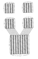
DCTでは、8×8画素の現ブロックが、DCT技法により8×8の係数行列Cijに変換されて量子化器へ出力される。なお、現ブロックは、上記差分のマクロブロックを図3のように分割して得られる。 In DCT, an 8 × 8 pixel current block is converted into an 8 × 8 coefficient matrix Cij by the DCT technique and output to a quantizer. The current block is obtained by dividing the macro block of the difference as shown in FIG.
図4のように、係数行列Cijは、或る除数Qij(量子化ステップ幅q×各係数行列Cijに適当な定数Kij)で除算され、余りは丸められる。量子化された係数行列C’ijはジグザグ走査され、可変長符号化器へ出力される。定数Kijは、量子化テーブルにより与えられる。 As shown in FIG. 4, the coefficient matrix Cij is divided by a certain divisor Qij (quantization step width q × appropriate constant Kij for each coefficient matrix Cij), and the remainder is rounded. The quantized coefficient matrix C'ij is zigzag scanned and output to the variable length encoder. The constant Kij is given by a quantization table.
定数Kij、及び/又は、qが増加すると、量子化器から出力される量子化された係数データC’ijは、より多くの「0」を含むようになり、圧縮レートは上昇する。適応量子化では、動画像符号化器から出力されるビットストリームのビットレートが監視され、量子化ステップ幅は、ビットレートが目標値に適合するようにセットされる。つまり、ビットレートが目標値より小さいときは量子化ステップ幅qは小さく制御され、ビットレートが目標値より大きいときは量子化ステップ幅qは大きく制御される。 As the constants Kij and / or q increase, the quantized coefficient data C'ij output from the quantizer includes more "0", and the compression rate increases. In adaptive quantization, the bit rate of the bit stream output from the video encoder is monitored, and the quantization step width is set so that the bit rate matches the target value. That is, when the bit rate is smaller than the target value, the quantization step width q is controlled to be small, and when the bit rate is larger than the target value, the quantization step width q is controlled to be large.
可変長符号化、例えば、ハフマン符号化では、量子化器から出力される量子化後の各係数データC’ijに対して、その出現頻度に応じた長さの符号が割り当てられる。 In variable length coding, for example, Huffman coding, a code having a length corresponding to the appearance frequency is assigned to each quantized coefficient data C′ij output from the quantizer.
(2)MPEG
或る1つのタイプの動画像符号化システムが、国際標準化機構(ISO)傘下の動画像標準化のための専門家委員会(MPEG)により提案されている。MPEG1標準はISO/IEC11172により与えられ、MPEG2標準は、ISO/IEC13818により与えられる。
(2) MPEG
One type of video coding system has been proposed by the Expert Committee for Video Standardization (MPEG) under the International Organization for Standardization (ISO). The MPEG1 standard is provided by ISO / IEC11172, and the MPEG2 standard is provided by ISO / IEC13818.
MPEGシステムでは、周知の多数のデータ圧縮技法が単一のシステムに集積されている。これらは、動き補償付き予測/内挿符号化、DCT、適応量子化、及びVLCを含む。 In an MPEG system, many well-known data compression techniques are integrated into a single system. These include motion compensated prediction / interpolation coding, DCT, adaptive quantization, and VLC.
図2のように、MPEG標準では、I,P,Bピクチャが用いられている。Iピクチャは、DCT,量子化、VLCのみで符号化されるイントラマクロブロックで構成される。即ち、動き補償付き予測/内挿符号化は使われない。Iピクチャは、動きベクトル無しで復号される。 As shown in FIG. 2, I, P, and B pictures are used in the MPEG standard. An I picture is composed of intra macroblocks encoded only by DCT, quantization, and VLC. That is, prediction / interpolation coding with motion compensation is not used. The I picture is decoded without a motion vector.
Pピクチャは、イントラマクロブロックと前方マクロブロックで構成される。Pピクチャは、先行するI又はPピクチャからの動きベクトルを用いて復号される。Bピクチャは、イントラマクロブロックと、前方予測マクロブロックと、後方予測マクロブロックと、内挿マクロブロックで構成される。Bピクチャは、先行及び後続するI又はPピクチャからの動きベクトルを用いて復号される。 A P picture is composed of an intra macroblock and a forward macroblock. A P picture is decoded using a motion vector from a preceding I or P picture. A B picture is composed of an intra macroblock, a forward prediction macroblock, a backward prediction macroblock, and an interpolation macroblock. B pictures are decoded using motion vectors from the preceding and following I or P pictures.
(3)符号化モード
6種類の動き補償、即ち、フレーム構造に於けるフレームMC、フィールドMC、デュアルプライムMC、及び、フィールド構造に於けるフィールドMC、16×8MC、デュアルプライムMCが、MPEG標準で許容されている。3種類の予測方向、即ち、前方向、後方向、及び双方向(前方向及び後方向)が、MPEG標準で許容されている。したがって、MPEG標準では、複数の動き補償モードがある。動きベクトルの個数は動き補償モードに依存している。そして、動き補償を伴わない予測符号化モードと、イントラ符号化モードがMPEG標準で許容されている。
(3) Coding mode Six types of motion compensation, ie, frame MC, field MC, dual prime MC in the frame structure, and field MC, 16 × 8 MC, dual prime MC in the field structure are MPEG standards. Is acceptable. Three types of prediction directions are allowed in the MPEG standard: forward, backward, and bidirectional (forward and backward). Therefore, in the MPEG standard, there are a plurality of motion compensation modes. The number of motion vectors depends on the motion compensation mode. A predictive coding mode without motion compensation and an intra coding mode are allowed by the MPEG standard.
したがって、MPEG標準には、複数種類の符号化モードがある。符号化に際しては、許容されている符号化モードの中から最適な符号化モードが各マクロブロックについて選択される。例えば、画面間予測符号化に於いて、予測誤差が最小の符号化モードが選択される。また、最小の予測誤差が所定の閾値を越える場合は、イントラ符号化モードが選択される。ここで、予測誤差は、例えば、現マクロブロックと参照マクロブロックの差の二乗誤差の平均値や、絶対値の平均値で与えられる。 Therefore, the MPEG standard has a plurality of types of encoding modes. In encoding, an optimal encoding mode is selected for each macroblock from among the allowable encoding modes. For example, in inter-picture prediction encoding, an encoding mode with the smallest prediction error is selected. In addition, when the minimum prediction error exceeds a predetermined threshold, the intra coding mode is selected. Here, the prediction error is given by, for example, the average value of the square error of the difference between the current macroblock and the reference macroblock, or the average value of the absolute value.
(4)従来技術
動きベクトル検出に関連する従来技術としては、特許文献1、特許文献2、特許文献3、特許文献4、特許文献5、特許文献6等の公報がある。イントラ符号化とインター符号化を選択する選択回路に関連する従来技術としては、特許文献7、特許文献8等の公報がある。動き付き予測/内挿符号化器、DCT、適応量子化器、及びVLCを有するエンコーダから出力される符号量に関連する従来技術としては、特許文献9、特許文献10、特許文献11等の公報がある。
本発明の第1の課題について、説明する。従来においては、各種動き補償モードの中では、予測誤差が一番最低になる動き補償モードが選択されている。しかし、特許文献9(H04N7/13)に示されるように、画像を実際に符号化したときの符号量は、この予測誤差に比例するものではない。また、特許文献10(H04N7/137)に示されるように、符号化時の符号量に応じてモード選択することが知られている。また、特許文献11(H04N7/137)に示されるように、動き補償予測符号化を行った場合に、画像自身の符号量だけでなく、動きベクトルの符号量も考慮することが知られている。 The first problem of the present invention will be described. Conventionally, among the various motion compensation modes, the motion compensation mode that minimizes the prediction error is selected. However, as shown in Patent Document 9 (H04N7 / 13), the code amount when an image is actually encoded is not proportional to the prediction error. Further, as shown in Patent Document 10 (H04N7 / 137), it is known to select a mode in accordance with a code amount at the time of encoding. Also, as shown in Patent Document 11 (H04N7 / 137), it is known that when motion compensated predictive coding is performed, not only the code amount of the image itself but also the code amount of the motion vector is considered. .
しかし、動きベクトルも含めた符号化時の符号量を実際に算出して、符号化のモードを決定するものは、従来においては、存在しない。本願の第1の目的は、動きベクトル含む実際の符号量を考慮した動き補償モード選択方法を提供することである。また、本発明の第2の課題は、このような動画像圧縮符号化装置を提案することである。 However, there is no conventional method for determining a coding mode by actually calculating a coding amount including a motion vector. A first object of the present application is to provide a motion compensation mode selection method considering an actual code amount including a motion vector. A second object of the present invention is to propose such a moving image compression coding apparatus.
本発明の第3の課題について、説明する。従来においては、各種動き補償モードの中では、予測誤差が一番最低になる動き補償モードが選択されている。ところが、後段の量子化回路(118)での量子化ステップ幅(q)が大きな場合(圧縮率が大きい場合)においては、再生画像の画質は劣化する可能性が高い。 The third problem of the present invention will be described. Conventionally, among the various motion compensation modes, the motion compensation mode that minimizes the prediction error is selected. However, when the quantization step width (q) in the subsequent quantization circuit (118) is large (when the compression ratio is large), there is a high possibility that the quality of the reproduced image is deteriorated.
このような場合は、予測誤差が一番最低になる動き補償モードの予測符号化を行っても、予測誤差が2番目に最低になる動き補償モードで予測符号化しても、あまり大差がつかない可能性が高いと考えられる。又、このような場合は、予測誤差が一番最低になる動きベクトルで、予測符号化しても、予測誤差が2番目に最低になる動きベクトルで予測符号化しても、復号画像の画質にあまり大差がつかない可能性が高いと考えられる。 In such a case, even if predictive coding is performed in the motion compensation mode in which the prediction error is the lowest, even if predictive coding is performed in the motion compensation mode in which the prediction error is second lowest, there is not much difference. The possibility is considered high. In such a case, even if the prediction vector is the motion vector with the lowest prediction error and the prediction vector is encoded with the motion vector with the second lowest prediction error, the quality of the decoded image is not much. It is likely that there will be no significant difference.
しかし、従来においては、圧縮率と動き補償動作とを結び付ける考えはなかった。本願の第3の目的は、この新規の認識に関わるものである。つまり、圧縮率が大きければ、動きベクトルの検出精度又は動き補償モード選択精度が高くても、復号画像の画質的には意味は少ない。また、圧縮率が大きい場合は、実際の符号化における符号量が少ないものが、切望されている状況である。 However, in the past, there was no idea of connecting the compression rate and the motion compensation operation. The third object of the present application relates to this new recognition. That is, if the compression rate is large, even if the motion vector detection accuracy or the motion compensation mode selection accuracy is high, there is little meaning in terms of the image quality of the decoded image. Further, when the compression rate is large, a situation in which a small amount of code in actual encoding is desired.
そこで、圧縮率等に応じて、動き補償動作を好適に変更できればよい。本願の第3の課題は、動き補償関連回路に圧縮率等を知らせることを課題とする。また、ビットストリーム全体の符号量は、必ずしも画像間の予測誤差だけによって決まる訳ではない。即ち、符号化されるものは、差分ブロックまたは処理ブロックの画素値だけではなく、動き補償モード情報、動きベクトル、その他のパラメータ等があり、これらは、動き補償モードによって個数が異なる。また、例えば、動きベクトルの値によっては、却って符号量を増加させることもある。リアルタイムに動画像圧縮データを復号するためには、符号量制御は必須であるから、ある画像の一部分の符号量が増加すると、他の部分の符号量は少なくせざるを得なくなり、全体の画質が劣化することもあり得る。従って、ある一部分の画像間の予測誤差が最小になったとしても、符号量が増加すれば、全体の画質劣化につながることもある。特に、低ビットレートにおける符号化では、画質よりも符号量を減らすことが重要になってくる。 Therefore, it is only necessary that the motion compensation operation can be suitably changed according to the compression rate or the like. The third problem of the present application is to notify the motion compensation related circuit of the compression rate and the like. Also, the code amount of the entire bitstream is not necessarily determined only by the prediction error between images. That is, what is encoded is not only the pixel values of the difference block or processing block, but also motion compensation mode information, motion vectors, other parameters, etc., and the number of these varies depending on the motion compensation mode. For example, depending on the value of the motion vector, the code amount may be increased instead. Since the code amount control is indispensable in order to decode moving image compressed data in real time, if the code amount of one part of an image increases, the code amount of the other part must be reduced, and the overall image quality is reduced. May deteriorate. Therefore, even if the prediction error between some images is minimized, if the code amount increases, the overall image quality may be deteriorated. In particular, in encoding at a low bit rate, it is important to reduce the amount of code rather than image quality.
請求項1の発明は、対応する現映像符号に符号化される対象の現映像データの符号化モードを適応的に選択する方法に於いて、参照映像データを参照し、前記現映像データとの予測誤差を各符号化モードについて各々求め、前記各符号化モードの予測誤差と前記符号化の圧縮率に応じて変更されるしきい値とを比較し、前記しきい値より小さな予測誤差の符号化モードについて、各々が現映像符号とその符号化パラメータを含む総符号の量に関係する値を求め、前記総符号の量がもっとも少ない符号化モードを選択する、選択方法である。
The invention of
本発明では、動画像の圧縮、記録、伝送に於いて、ビットストリーム全体の符号量を最適な値にすることができる。 In the present invention, the code amount of the entire bit stream can be set to an optimum value in the compression, recording and transmission of moving images.
以下では、MPEGビデオエンコーダの用語で記述されているが、それは、イメージフレームが部分的に動き補償付き予測や適応量子化に基づいて符号化される他のタイプのビデオエンコーダが使われる得ることを意図している。 In the following, described in MPEG video encoder terminology, it is understood that other types of video encoders may be used in which image frames are partially encoded based on motion compensated prediction or adaptive quantization. Intended.
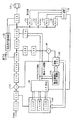
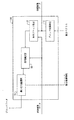
(1)典型的なMPEGエンコーダ(図1).
図1は典型的なMPEGエンコーダを示す。このシステムでは、イメージを記述するビデオ信号が、画面並び換え器111に供給される。画面並び換え111器は画面順を並び換える。現フレームが時間的に先行するフレームにより参照される場合は、該現フレームが先行して復号されて画像メモリ142に格納されている必要がある。このため、現フレームとその時間的な先行フレームとは、現フレームが最初に処理されるように並び換えられる。例えば、時間的に先行するBピクチャによって参照される現I又はPピクチャは、先にマクロブロック変換器112へ出力される。
(1) Typical MPEG encoder (FIG. 1).
FIG. 1 shows a typical MPEG encoder. In this system, a video signal describing an image is supplied to the
画面並び換え器111で並び換えられたビデオデータは、マクロブロック変換器112に入力される。例えば通常の2ポートメモリを含むマクロブロック変換器112は、信号を、ラスタスキャンフォーマットから16×16画素のマクロブロックフォーマットに変換して、減算器114と動き検出器146へ出力する。マクロブロックフォーマットでは、イメージの各フレームは、16×16画素の行列にアレンジされた256画素を有するマクロブロックの集まりとして表される。マクロブロック変換器112は、これらの画素値をマクロブロック毎に減算器114へ供給する。
The video data rearranged by the
非イントラ符号化モードでは、減算器114は、画像メモリ142から供給される参照マクロブロックを、マクロブロック変換器112から供給される対応する現マクロブロックから減算して、動き補償された差分マクロブロックである差分マクロブロックをブロック変換器116へ出力する。イントラ符号化モードでは、減算器114は、マクロブロック変換器112から供給された現マクロブックを、ブロック変換器116へ出力する。
In the non-intra coding mode, the
ブロック変換器116は、図3に示すように、信号を、16×16画素のマクロブロックフォーマットから、8×8画素の4個のブロックフォーマットに変換して、DCT118へ出力する。ブロック変換器116は、これらの画素値をブロック毎にDCT118へ供給する。 As shown in FIG. 3, the block converter 116 converts the signal from a macro block format of 16 × 16 pixels into four block formats of 8 × 8 pixels and outputs them to the DCT 118. The block converter 116 supplies these pixel values to the DCT 118 for each block.
DCTプロセッサ118は、各ブロックの画素値にDCT演算を適用して、DCT係数行列Cijのブロックに変換する。各ブロックは、図4(c)に示すようなジグザグスキャンを用いて、64個の係数Cijのリニアストリームにアレンジされる。何れのブロックに於いても、これらの係数Cijの先頭は、画素ブロックの直流(DC)空間周波数成分を表す。また、残りの係数Cijは、次に高い空間周波数成分である。 The DCT processor 118 applies a DCT operation to the pixel values of each block to convert them into blocks of the DCT coefficient matrix Cij. Each block is arranged into a linear stream of 64 coefficients Cij using a zigzag scan as shown in FIG. In any block, the head of these coefficients Cij represents the direct current (DC) spatial frequency component of the pixel block. The remaining coefficient Cij is the next highest spatial frequency component.
DCTプロセッサ118によって供給される係数値は、量子化器120に適用される。量子化器120は、各係数値Cijを、割り当てられたビット数を持つ2値に変換する。概して、低い順番の係数に対しては、高い順番の係数に対してよりも、大きいビット数が用いられる。その理由は、人間の目が、低空間周波数のイメージ成分に対してよりも、高空間周波数のイメージ成分に対しての方が、より感受性が鈍いためである。この操作は、例えば、各係数を、空間周波数に比例する各々異なる値によって除算することで実行され得る。
The coefficient values supplied by the DCT processor 118 are applied to the
また、各係数値に割り当てられたビット数は、量子化コントローラ132から供給される量子化ステップ幅qに応じて変更され得る。量子化ステップ幅qは、各係数が、量子化行列Kijによって除算される前又は除算された後に、各係数を除算するために適用される。量子化器120はデジタル値の流れを産み、それは、VLC124と、逆量子化器136へ入力される。圧縮レートを制御する量子化ステップ幅qは可変である。
Further, the number of bits assigned to each coefficient value can be changed according to the quantization step width q supplied from the
VLC124は、量子化器120からのデータを、例えば、ランレングスのハフマンタイプのコードを用いて符号化する。ハフマンタイプのコードを用いて、VLC124は、出現頻度の高いデータ値の結合と0の連続に対して、より少ないビット数を割り当てる。
The VLC 124 encodes the data from the
第2のVLC134がある。これは、ともにモード決定器150からのデータであるマクロブロックタイプデータMBTと動きベクトルデータとを、可変長符号化する。
There is a second VLC 134. In this case, the macroblock type data MBT and the motion vector data, both of which are data from the
VLC124で発生された符号と、VLC134で発生された符号は、挿入器(FIFOメモリ)126に入力する。この挿入器(FIFOメモリ)126は、それらを結合して、ビットストリームをバッファメモリ(FIFOメモリ)128へ出力する。このビットストリームはバッファメモリ(FIFOメモリ)128に格納され、光ディスクのような記録媒体130に記録される。
The code generated by the VLC 124 and the code generated by the VLC 134 are input to an inserter (FIFO memory) 126. The inserter (FIFO memory) 126 combines them and outputs the bit stream to the buffer memory (FIFO memory) 128. This bit stream is stored in a buffer memory (FIFO memory) 128 and recorded on a
MPEGエンコーダでは、バッファメモリ128のデータ量が監視され、MPEGデコーダのバッファメモリに格納されるデータ量がシミュレートされる。これにより、量子化ステップ幅qが、MPEGデコーダのバッファメモリがオーバーフローしないように制御される。即ち、量子化ステップ幅qは、バッファメモリ128と、バッファメモリ128の容量変化を参照して決定される。量子化ステップ幅qとしては、通常は、値1〜31が採用される。
In the MPEG encoder, the amount of data in the
BピクチャとPピクチャでは、差分値がDCTされて出力されため、データ量はIピクチャより少なくなる。この理由から、MPEGでは、目標データ量はピクチャタイプに応じて割り当てられる。また、発生されたデータ量は、各スライスやマクロブロック毎に監視される。データ量は目標値と比較され、量子化コントローラ132によって評価される。例えば、発生符号量が目標値より大きい場合は量子化ステップ幅qは大きくされ、量子化は粗くなる。この制御は、量子化コントローラ132により行われる。他方では、発生符号量が目標値より小さい場合は量子化ステップ幅qは小さくされ、量子化は細かくなる。バッファメモリ128はフレームタイプ、フレーム特性、量子化ステップ幅に起因して生ずる発生符号量の変動を緩和する。
In the B picture and the P picture, the difference value is DCTed and output, so that the data amount is smaller than that of the I picture. For this reason, in MPEG, the target data amount is assigned according to the picture type. Further, the generated data amount is monitored for each slice or macroblock. The amount of data is compared with the target value and evaluated by the
なお、MPEG標準は、一般的ではないが、固定ビットレートに加えて、可変ビットレートを許容している。ビットレートが変動する場合は、量子化ステップ幅qは当然に変動する。 Note that the MPEG standard allows a variable bit rate in addition to a fixed bit rate, although it is not common. When the bit rate varies, the quantization step width q naturally varies.
逆量子化器136と逆DCT138で構成される局部デコーダは、先行又は後続フレームのための参照イメージデータを再生する。再生されたフレームは、画像メモリ142に格納される。その後、減算器114へ前述のように出力される。加算器140は、上記再生データが差分データである場合に、参照フレーム内の動き補償された参照マクロブロックを上記再生データに加算する。
A local decoder composed of an inverse quantizer 136 and an
画像メモリ142は、少なくとも2つのイメージデータを格納する。IピクチャとIピクチャ、IピクチャとPピクチャ、PピクチャとPピクチャのペアの何れかである。画像メモリ142は、各マクロブロックを参照用に出力する。また、動きベクトル検出用に動きベクトル検出器146へ出力する。また、モード決定用にモード決定器150に出力する。動きベクトル検出器146では、現マクロブロックに最も似ている領域が、例えば、予測誤差を用いて参照フレーム内から探し出される。動きベクトル検出器146は、前方検出器146F、双方検出器146M、後方検出器146Bから成る。前方検出器146Fは、前方動きベクトルを検出して、その予測誤差とともに動き補償モード選択器148に出力する。双方検出器146Mは、両方向の動きベクトルを検出して、その予測誤差とともに動き補償モード選択器148に出力する。後方検出器146Bは、後方動きベクトルを検出して、その予測誤差とともに動き補償モード選択器148に出力する。
The
動き補償モード選択回路148は、最も予測誤差の少ないものを選択する。つまり、3つの動きベクトル検出回路146F,146M,146Bからの予測誤差出力の内、後方向動きベクトル検出回路146Bからの予測誤差がもっとも少なければ、動き補償モード選択回路148は、後方向動き補償を指示するマクロブロックタイプ情報を出力するとともに、後方向動きベクトル検出回路146Bからの動きベクトルを出力する。
The motion compensation
また、同様に、3つの動きベクトル検出回路146F,146M,146Bからの予測誤差出力の内、双方向動きベクトル検出回路146Mの予測誤差がもっとも少なければ、動き補償モード選択回路148は、双方向動き補償を指示するマクロブロックタイプ情報を出力するとともに、双方向動きベクトル検出回路146Mからの動きベクトルを出力する。
Similarly, if the prediction error of the bidirectional motion
前段の動き補償モード選択回路148により、マクロブロックを動き補償予測符号化(インター符号化)する場合に、最も、適切な動き補償の方向が選択済みである。しかし、画像のパターンによっては、マクロブロックを符号化する場合に画面内符号化(イントラ符号化)の方が、効率的な場合もある。モード決定回路150は、このイントラ/インターの決定を行う。モード決定回路150については、例えば、特許文献7、特許文献8に示されるように、良く知られている。
When the macroblock is subjected to motion compensation predictive coding (inter coding) by the motion compensation
モード決定回路150は、マクロブロック変換器112からのマクロブロックの画像の分散値を求める。また、動き補償モード選択回路148からのマクロブロックタイプ情報及び動きベクトルに基づいて動き予測符号化した場合の差分画面の分散値を求める。このために、動き補償モード選択回路148からのマクロブロックタイプ情報及び動きベクトルに基づいて、予測マクロブロックを、動き補償読み出し制御回路144を介して画像メモリ142から読み出して、このモード決定回路150に入力する。
The
モード決定回路150は、この予測マクロブロックとマクロブロック変換器112からのマクロブロックとの差分画面のマクロブロックを得る。そして、このマクロブロックの分散値を求める。このように求めた2つの分散値を比較することによりマクロブロックのタイプを決定する。この決定に基づいて、マクロブロックタイプ情報を出力する。また、マクロブロックタイプ情報として、インター符号化が選ばれた場合は、動きベクトル情報も出力する。
The
MPEGエンコーダの動作を、図1〜図4を参照しつつ簡単に説明する。まず、画面並び替え回路111は、数十枚の画面から、一枚の画面が画面単位内で圧縮が行われるIピクチャを設定し、それ以外の画面は、動き補償を用いた画面単位間での圧縮が行われBピクチャ・Pピクチャとする。画面並び替え回路111は、この設定に合わせて画面の並び替えを行う。
The operation of the MPEG encoder will be briefly described with reference to FIGS. First, the
そして、画面単位内で圧縮を行うイントラマクロブロックでは、ブロック化回路112で画面を複数の領域に分割し、減算回路114を素通りし、DCT回路118でそれぞれに二次元離散余弦変換(DCT)を行って周波数成分を求める。このDCT処理の単位は、8×8画素単位のブロックである。
In an intra macroblock that performs compression within a screen unit, the
画面(図4(a))はDCT処理されて、図4(b)に示されるように、周波数成分に変換される。この結果、左上が低周波領域となり、右下が高周波領域となる。得られた周波数成分は、図4(d)で示される値によって除算される。この除算が、量子化である。この量子化時に、人間の視覚特性が高周波に対して鈍感なことを利用し、低周波側には多くの符号を割り当て、高周波側の符号量を少なくするように、量子化する。つまり、前述の値Qijは、高周波に当る領域の値が大きく設定された量子化マトリックスKijと、量子化回路120からの量子化ステップ幅qとの、乗算結果である。こうして得られたデータを図4(c)の如く、低周波側から高周波側へジグザグに取り、この結果を可変長符号化する。
The screen (FIG. 4 (a)) is subjected to DCT processing and converted into frequency components as shown in FIG. 4 (b). As a result, the upper left is a low frequency region and the lower right is a high frequency region. The obtained frequency component is divided by the value shown in FIG. This division is quantization. At the time of quantization, using the fact that human visual characteristics are insensitive to high frequencies, quantization is performed so that many codes are assigned to the low frequency side and the code amount on the high frequency side is reduced. That is, the above-described value Qij is a multiplication result of the quantization matrix Kij in which the value of the region corresponding to the high frequency is set large and the quantization step width q from the
また、画面単位間で圧縮を行うインターマクロブロックでは、ブロック化回路112の出力(現画面)と、動き補償による予測画面とを、減算回路114に入力して差分をとり、以降は、Iピクチャと同等に符号化する。このようにBピクチャとPピクチャは、差分を伝送するので、データ量は小さい。したがって、このままでは、符号化時のデータ量(ビット量)が、画面によって異なる。しかし、MPEGでは、転送ビットレートは、ほぼ一定である。
Further, in an inter macroblock that performs compression between screen units, the output (current screen) of the blocking
このために、データ量が多い画面が続くと、バッファメモリ128がオーバーフローしてしまう恐れがある。そこで、量子化マトリックス(図4(d)の乗数である量子化ステップ幅qの値を変更することにより量子化の粗さを変更して(圧縮率を制御して)、発生データ量をフィードバック制御することにより、オーバーフローを防止している。
For this reason, if a screen with a large amount of data continues, the
動きベクトル検出回路146は、動きベクトルを検出する。動き補償モード選択回路148は、このマクロブロックの適切な符号化モードを検出する。動きベクトル検出回路146、動き補償モード選択回路148では、いくつかある動き補償予測モードのすべての内で、予測誤差が最小になる動き補償モードを選択する。モード決定回路150は、最終的にマクロブロックタイプを決定し、このマクロブロックタイプ情報と、動きベクトルを出力する。
The motion
(2)第1実施例(図5〜図8).
図5において、図1と同一部分には、同一符号を付し説明を省略する。図5において、50は、イントラ符号化用のバッファである。52、54、56は、インター符号化用のバッファである。各バッファは、各動き補償モードにおける、動きベクトル等の付属データを含む画像の符号化データを格納する。
(2) First embodiment (FIGS. 5 to 8).
In FIG. 5, the same parts as those of FIG. In FIG. 5, 50 is a buffer for intra coding. 52, 54 and 56 are buffers for inter coding. Each buffer stores encoded data of an image including attached data such as a motion vector in each motion compensation mode.
52は、前方向の動き補償予測符号化を行った場合に発生する符号を一時格納するバッファである。54は、双方向の動き補償予測符号化を行った場合に発生する符号を一時格納するバッファである。56は、後方向の動き補償予測符号化を行った場合に発生する符号を一時格納するバッファである。
A
58は、モード選択回路である。モード選択回路58は、バッファ50、52、54、56の符号量を検出し、符号量が最も少ないモードを選択して、モード決定回路60に出力する。このモード選択回路58は、複数の異なる動き補償予測符号化モードより動画像信号を符号化した場合に、実際に生じる動きベクトルを含めた符号量を検出するモード別発生符号量検出手段58を成している。
58 is a mode selection circuit. The mode selection circuit 58 detects the code amount of the
モード決定回路60は、符号化する場合のモードを決定する。モード決定回路60は、少なくても、モード選択回路58の出力により、符号化する動き補償モードを選択する適応型動き補償モード選択手段60を成している。
The
第1実施例の動作を説明する。Bピクチャを符号化する場合には、各マクロブロックについて、モードを決定しなくてはならない。動き検出回路146では、符号化するマクロブロックについて、各モードの動きベクトルを求める。
The operation of the first embodiment will be described. When encoding a B picture, the mode must be determined for each macroblock. The
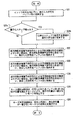
これより、本願の特徴を記載する。モード決定回路60は、図6のS1に示すように、まず、イントラ符号化が行われるように本エンコーダを制御する。そして、この時に発生する符号をバッファ50に格納する。
The characteristics of the present application will now be described. As shown in S1 of FIG. 6, the
次に、モード決定回路60は、図6のS2に示すように、まず、インター符号化のうちの前方向予測符号化が行われるように本エンコーダを制御すると共に、対応する前方向の動きベクトルを出力する。そして、この時に発生する符号をバッファ52に格納する。
Next, as shown in S2 of FIG. 6, the
モード決定回路60は、図6のS3に示すように、インター符号化のうちの双方向予測符号化が行われるように本エンコーダを制御すると共に、対応する双方向の動きベクトルを出力する。そして、この時に発生する符号をバッファ54に格納する。
As shown in S3 of FIG. 6, the
モード決定回路60は、図6のS4に示すように、インター符号化のうちの後方向予測符号化が行われるように本エンコーダを制御すると共に、対応する後方向の動きベクトルを出力する。そして、この時に発生する符号をバッファ56に格納する。
As shown in S4 of FIG. 6, the
モード選択回路58は、図6のS5に示すように、バッファ50、52、54、56の符号量を検出し、もっとも符号量の少ないバッファを検出し、モード決定回路60に知らせる。つまり、モード選択回路58は、バッファ50、52、54、56の符号量を検出し、モード決定回路60は、図6のS6に示す如く、このもっとも少ない符号量に対応するモードでの符号化を決定する。ここからは、従来と同様に通常の符号化処理を行う。
The mode selection circuit 58 detects the code amount of the
このモードの決定について述べる。例えば、バッファ50の符号量が最も少ないのであれば、この時のマクロブロックに適した符号化は、イントラ符号化である。従って、モード選択回路58が、これを検出し、これをモード決定回路60に伝えると、モード決定回路60は、イントラ符号化を行うように本エンコーダを制御するために、イントラ符号化を示すマクロブロックタイプ情報を出力する。
The determination of this mode will be described. For example, if the code amount of the
また、バッファ56の符号量がもっとも少ないのであれば、この時のマクロブロックに適した符号化は、後方向の動き補償予測符号化である。従って、モード選択回路58が、これを検出し、これをモード決定回路60に伝えると、モード決定回路60は、後方向の動き補償予測符号化を行うように本エンコーダを制御するために、後方向予測符号化を示すマクロブロックタイプ情報を出力すると共に後方向の動きベクトルを出力する。
If the code amount of the
このように、この第1実施例によれば、実際の動きベクトルを含む符号量により、モードを選択しているので、発生符号量が少ない動き補償モードを選択することが出来る。なお、この第1実施例は、ハード的な概略回路ブロック図で説明したが、本願は、当然、MPEGの符号化をソフトウエアで行う場合に、採用しても良い。また、この第1実施例では、マクロブロックの符号化モードとしてイントラ符号化を含んでいるが、本願はこれに限定されるものではなく、複数種類の動き補償モードだけでもよい。また、この第1実施例は、3つの動き補償モードについて説明したが、本願は、当然、これだけに限定されるわけでなく、例えば、MPEG2のフレーム構造におけるフレーム予測とフィールド予測のモード選択にも利用できる。また、MPEG2のフィールド構造における16×16単位の予測と16×8単位の予測モードの選択にも利用できる。また、Pピクチャに用いても良い。 Thus, according to the first embodiment, since the mode is selected based on the code amount including the actual motion vector, it is possible to select a motion compensation mode with a small generated code amount. Although the first embodiment has been described with reference to a hardware schematic circuit block diagram, the present application may naturally be adopted when MPEG encoding is performed by software. In the first embodiment, intra coding is included as a macroblock coding mode. However, the present application is not limited to this, and only a plurality of types of motion compensation modes may be used. In the first embodiment, three motion compensation modes have been described. However, the present application is naturally not limited to this. For example, the mode selection for frame prediction and field prediction in the MPEG2 frame structure is also possible. Available. It can also be used for 16 × 16 unit prediction and 16 × 8 unit prediction mode selection in the MPEG2 field structure. Moreover, you may use for a P picture.
また、第1実施例では、常に、実際の符号量からモードを選択している。しかし、本願は、これに限定されるわけでない。例えば、十分にバッファ128に余裕があり、量子化ステップ幅qが最小の場合(圧縮率が小さな場合)は、従来と同様にしてモードを決定してもよい。そして、例えば、バッファ128に余裕がなくなる可能性が高まったり、量子化ステップ幅qが増加した場合(圧縮率が大きな場合)に、発生符号量を少なくするために、上述の処理を行うように構成してもよい。
In the first embodiment, the mode is always selected from the actual code amount. However, the present application is not limited to this. For example, when the
また、この第1実施例は、3つの動き補償モードについては、全て実際に符号化した。しかし、本願は、当然、これだけに限定されるわけでなく。例えば、動き補償モードにおいて、予測誤差が小さい上位2つの動き補償モードについて全て実際に符号化するようにしてもよい。このようにすれば、プログラムにおける演算量を低減でき、処理スピードの高速化が図れる。なお、前述したように予測誤差が少ない場合に必ずしも符号量が少ないとは限らないが、その可能性が高いからである。 In the first embodiment, all the three motion compensation modes are actually encoded. However, the present application is naturally not limited to this. For example, in the motion compensation mode, all of the top two motion compensation modes with small prediction errors may be actually encoded. In this way, the calculation amount in the program can be reduced, and the processing speed can be increased. As described above, when the prediction error is small, the code amount is not always small, but the possibility is high.
また、上述の如く、予測誤差が少ない上位2つの動き補償モードについて、全て実際に符号化するのではなく、図7の如く、予測誤差が所定閾値より少ない動き補償モードについて実際に符号化するようにしてもよい。このようにすると、プログラムにおける演算量を低減でき、処理スピードの高速化が図れる。 Further, as described above, the upper two motion compensation modes with few prediction errors are not actually encoded, but the motion compensation modes with less prediction errors than a predetermined threshold are actually encoded as shown in FIG. It may be. In this way, the calculation amount in the program can be reduced, and the processing speed can be increased.
さらに、この図7の所定閾値の値を、量子化ステップ幅qに応じて変更してもよい。つまり、図8に示すように、量子化ステップ幅qが大きい場合、実際の符号量を出来るだけ検出するモードを選択した。つまり、バッファ128に余裕がない場合は、発生符号量の低減が切望されるので、この様な場合には、少しでも発生符号量を少なくする可能性を高めるために行う。
Furthermore, the value of the predetermined threshold in FIG. 7 may be changed according to the quantization step width q. That is, as shown in FIG. 8, when the quantization step width q is large, a mode in which the actual code amount is detected as much as possible is selected. That is, when there is no room in the
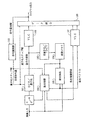
(3)第2実施例(図9).
図9において、図1及び図5と同一の部分には、同一符号を付して説明を省略する。この実施例は、本エンコーダでの圧縮率又は発生符号量に関連する値に応じて、符号化時のモード選択動作を変更するものである。なお、本エンコーダでの圧縮率又は発生符号量に関連する値としては、挿入器126からのマクロブロック毎の発生符号量、バッファ128の残り容量、量子化ステップ幅qがある。
(3) Second embodiment (FIG. 9).
9, parts that are the same as those in FIGS. 1 and 5 are given the same reference numerals, and descriptions thereof are omitted. In this embodiment, the mode selection operation at the time of encoding is changed according to the value related to the compression rate or generated code amount in this encoder. Note that values related to the compression rate or generated code amount in this encoder include the generated code amount for each macroblock from the
この実施例では、量子化ステップ幅qを用いた。また、この実施例では、発生符号量に応じてモード選択動作を行う場合に、実際の発生符号量を検出するのではなく、分散値から発生符号量を予測した。図9において、62は、動き補償モード選択回路である。Lは、量子化ステップ幅qを動き補償モード選択回路62に伝送する報知手段としての信号線路である。 In this embodiment, the quantization step width q is used. Further, in this embodiment, when the mode selection operation is performed according to the generated code amount, the actual generated code amount is not detected, but the generated code amount is predicted from the variance value. In FIG. 9, reference numeral 62 denotes a motion compensation mode selection circuit. L is a signal line as a notification means for transmitting the quantization step width q to the motion compensation mode selection circuit 62.
前記動き補償モード選択回路62は、予測誤差が所定の閾値より小さいモードをまず検出する。なお、この所定の閾値は、量子化ステップ幅qに応じて変更される。この量子化ステップ幅qは、信号線路Lにより動き補償モード選択回路62に伝送されている。量子化ステップ幅qが大きい場合には、前述の閾値も大きく変更される。 The motion compensation mode selection circuit 62 first detects a mode in which the prediction error is smaller than a predetermined threshold. The predetermined threshold is changed according to the quantization step width q. The quantization step width q is transmitted to the motion compensation mode selection circuit 62 through the signal line L. When the quantization step width q is large, the above-described threshold value is also greatly changed.
そして予測誤差と閾値との比較し、閾値より小さな予測誤差のモードを検出する。これに該当するモードがなければ、動き補償モード選択回路62は、最も予測誤差の小さいものを選択する。つまり、このモードを示すマクロブロックタイプ情報を出力するとともに、このモードの動きベクトルを出力する。また、これに該当するモードが1つのみであれば、動き補償モード選択回路62は、このモードを選択する。つまり、このモードを示すマクロブロックタイプ情報を出力するとともに、このモードの動きベクトルを出力する。 Then, the prediction error is compared with the threshold value, and a prediction error mode smaller than the threshold value is detected. If there is no mode corresponding to this, the motion compensation mode selection circuit 62 selects the one with the smallest prediction error. That is, the macro block type information indicating this mode is output, and the motion vector of this mode is output. If there is only one mode corresponding to this, the motion compensation mode selection circuit 62 selects this mode. That is, the macro block type information indicating this mode is output, and the motion vector of this mode is output.
また、これに該当するモードが2つ以上であれば、動き補償モード選択回路62は、更に選択処理を行う。この選択処理のために、分散値による処理を行う。動き補償モード選択回路62は、複数のモードの一つについて、マクロブロックタイプ情報及び動きベクトルに基づいて、動き予測符号化した場合の誤差画面の分散値を求める。 If there are two or more modes corresponding to this, the motion compensation mode selection circuit 62 further performs a selection process. For this selection process, a process using a variance value is performed. The motion compensation mode selection circuit 62 obtains a variance value of an error screen when one of a plurality of modes is subjected to motion prediction encoding based on the macroblock type information and the motion vector.
このため、このモードに対応するマクロブロックタイプ情報及び動きベクトルを動き補償読み出し制御回路144に出力する。これにより、画像メモリ142からは、対応する予測画面のマクロブロックが、動き補償モード選択回路62へ出力される。
Therefore, the macro block type information and the motion vector corresponding to this mode are output to the motion compensation
動き補償モード選択回路62は、マクロブロック変換器112からの現マクロブロックの画像と、画像メモリ142からの予測画面のマクロブロックの差分を求め、更に、この差分画面マクロブロックの分散値を求める。動き補償モード選択回路62は、残りのモードについても、同様に処理して、それぞれのモードにおける分散値を求める。
The motion compensation mode selection circuit 62 obtains the difference between the current macroblock image from the
そして、動き補償モード選択回路62は、この分散値を比較して、動き補償モードを選択する。このように、動き補償モード選択回路62は、この動きベクトル検出回路(各モード別予測誤差検出手段:146)の出力と前記圧縮率に関連した値とを参考に前記動き補償モードを選定する、動き補償モード選択手段62を成している。また、この動き補償モード選択回路62は、少なくても前記圧縮率に関連した値に応じて動き補償モードを選択する処理を変更する動き補償モード選択手段62を成している。なお、この実施例では、動き補償モードによる差分画面の分散値をモード決定回路150でもう一度求めるようにしているが、これは、当然、回路をまとめてもよい。
Then, the motion compensation mode selection circuit 62 compares the dispersion values and selects the motion compensation mode. Thus, the motion compensation mode selection circuit 62 selects the motion compensation mode with reference to the output of the motion vector detection circuit (prediction error detection means for each mode: 146) and the value related to the compression ratio. The motion compensation mode selection means 62 is formed. In addition, the motion compensation mode selection circuit 62 includes motion compensation mode selection means 62 that changes the process for selecting the motion compensation mode in accordance with at least the value related to the compression ratio. In this embodiment, the variance value of the difference screen in the motion compensation mode is obtained once again by the
(4)動き補償付き予測符号化(図17,図18).
従来より一般に行なわれている動き補償つき予測符号化を用いた圧縮手法について、以下に概略を説明する。図17は、MPEG規格に基づく圧縮動作の構成図、図18は、動き補償モードを選択する動作の構成図である。図17に於いて、イントラ画像はまず、ブロック毎にDCT/量子化部101で、DCT及び量子化が行なわれる。
(4) Predictive coding with motion compensation (FIGS. 17 and 18).
An outline of a compression method using predictive coding with motion compensation, which is generally performed conventionally, will be described below. FIG. 17 is a block diagram of a compression operation based on the MPEG standard, and FIG. 18 is a block diagram of an operation for selecting a motion compensation mode. In FIG. 17, the intra image is first subjected to DCT and quantization in the DCT / quantization unit 101 for each block.
この際、符号量制御部108より与えられる目標符号量に応じて、量子化ステップ幅等が定められる。生成したデータは、VLC部102へ送られて可変長符号化(VLC)が行なわれる。符号化データは、前記量子ステップ幅値とデータ統合され一本のビットストリームを形成する。一方、前記符号化データは、逆量子化/逆DCT(IDCT)部103へも送られて復号化され、復号データ(以下、デコード画像)は、画像メモリ104へ蓄えられる。
At this time, the quantization step width and the like are determined according to the target code amount given from the code
次に、インター画像は、まず、動き検出部105で、マクロブロック毎に、参照ピクチャに対して動きベクトルを検出する。ここで参照ピクチャは、画像メモリ104に保持されているデコード画像である。複数の動き補償モードが許容されている場合には、各動き補償モード毎に動きベクトル検出を行なう。その後に、動き補償部106において、画像間予測誤差が最小となる動き補償モードまたは、動き補償を行なわないモードを選択する。
Next, in the inter image, first, the
選択したモードに対応する差分ブロックまたは処理ブロックは、DCT/量子化部101、次いでVLC部102へ送られて、イントラ画像と同様の圧縮処理が行なわれる。一方、動き補償部106で選択した前記モードの情報、及び動き補償を行う場合には対応する動きベクトル情報は、VLC部107へ送られて符号化される。最後にデータ統合部110において、各符号化情報が一本のビットストリームに統合されて出力される。生成ビットストリーム量は、符号量制御部108へ送られて、残存画像の符号化時に定める目標符号量の基準となる。
The difference block or processing block corresponding to the selected mode is sent to the DCT / quantization unit 101 and then to the
図18には、本構成の動き補償部106内部の詳細を記す。ここでは、まずブロック位置指定部11で、検出済みの動きベクトルデータを用いて、ピクチャ内の参照ブロック位置を指定し、参照ピクチャ内から、参照ブロックを切り出す。次に、差分ブロック生成部12で、前記参照ブロックと処理ブロックとの間の対応する画素値の差分を求め、差分ブロックを生成する。11〜13の動作は、複数の動き補償モードの各々及び動き補償を行わないピクチャ間予測符号化の各々について行う。但し、動き補償を行わない場合には、ブロック位置指定部11では、動きベクトルデータを用いず、処理マクロブロックと同じ座標を指定する。最小予測誤差選択部14では、各モードに対応する複数の差分ブロックを元に、画像間の予測誤差が最小になる動き補償モードを選択する。
FIG. 18 shows the details inside the
最後に、選択した動き補償モードによる動き補償つきピクチャ間予測符号化(非イントラ)と、ピクチャ間予測符号化を行わないモード(イントラ)のいずれかを選択する、イントラ/非イントラ判定をイントラ/非イントラ判定部15で行う。一般には、ピクチャ間予測符号化の予測誤差が一定の閾値を越えれば、ピクチャ間予測符号化は行わない(イントラ判定)。 Finally, the intra / non-intra determination is performed by selecting either the inter-picture predictive coding with motion compensation (non-intra) with the selected motion compensation mode or the mode (intra) without inter-picture predictive coding. This is performed by the non-intra determination unit 15. In general, if the prediction error of inter-picture predictive coding exceeds a certain threshold, inter-picture predictive coding is not performed (intra determination).
選択された動き補償モードの情報及び動きベクトルは、図17のVLC部107へ送られる。一方、対応する差分ブロック、または、動き補償を行なわないモードが選択された場合には、処理ブロックが、図17のDCT/量子化部101へ送られる。
The selected motion compensation mode information and motion vector are sent to the
(5)第3実施例(図10,図11).
本発明の第3実施例について述べる。図10は、本発明による動画像圧縮方法の構成の一例を示したもの、図11は、本発明による動き補償モード選択の詳細を示したものである。
(5) Third embodiment (FIGS. 10 and 11).
A third embodiment of the present invention will be described. FIG. 10 shows an example of the configuration of a moving image compression method according to the present invention, and FIG. 11 shows details of motion compensation mode selection according to the present invention.
図10に示す様に、この実施例の動作構成は、DCT及び量子化を行なうDCT/量子化部101及び可変長符号化を行なうVLC102、VLC107、逆量子化及びIDCTを行なう逆量子化/IDCT部103、少なくとも1枚以上のピクチャデータを格納する画像メモリ104、動き検出を行なう動き検出部105、動き補償を行なう動き補償部106、符号量制御を行なう符号量制御部108、種々の圧縮データを一本のビットストリームに統合するデータ統合部110で構成される。
As shown in FIG. 10, the operation configuration of this embodiment includes a DCT / quantization unit 101 that performs DCT and quantization, a
本発明において、従来技術と異なる点は、インター画像における動き補償モードの選択であるので、イントラ画像の圧縮動作については、述べない。インター画像の場合は、まず、動き検出部105で画像メモリに蓄えられた参照画像に対して動き検出を行ない、さらに動き検出部で得られた動きベクトルを用いて動き補償部106で動き補償を行なう。
In the present invention, the difference from the prior art is the selection of the motion compensation mode in the inter image, so the compression operation of the intra image will not be described. In the case of an inter image, first, motion detection is performed on the reference image stored in the image memory by the
動き補償部では、過去に符号化済みのビットストリームの量から得られる目標符号量を用いて、複数の動き補償モードの中から最適な動き補償モードを選択する。DCT/量子化器101では、選択された動き補償モードに基づく動き補償により生成した差分ブロックデータをDCT及び量子化によって圧縮する。 The motion compensation unit selects an optimal motion compensation mode from among a plurality of motion compensation modes using a target code amount obtained from the amount of a bit stream that has been encoded in the past. The DCT / quantizer 101 compresses the differential block data generated by motion compensation based on the selected motion compensation mode by DCT and quantization.
更にVLC部102において可変長符号化を行なう。
Further, the
一方、選択された動き補償モード情報と該動き補償モードに対応する動きベクトルは、VLC部107で可変長符号化される。データ統合部110では、上記圧縮データを統合して一つのビットストリームにし、出力する。
On the other hand, the selected motion compensation mode information and the motion vector corresponding to the motion compensation mode are variable length encoded by the
図11は、本実施例における、動き補償モード選択動作の詳細である。まず、ブロック位置指定部11において、検出済みの動きベクトルデータを用いて、参照ピクチャ内の、参照ブロックの位置を指定する。次に、差分ブロック生成部12において、処理ピクチャ内の処理ブロックと、前記参照ブロック位置に基づく参照ピクチャ内の参照ブロックとの対応する画素値の差分をとり、差分ブロックを生成する。
FIG. 11 shows details of the motion compensation mode selection operation in this embodiment. First, the block
符号量計算部23では、前記差分ブロックを符号化する場合に生成する符号量を求める。ここで、符号量の算出は、予め差分ブロックの各要素、パターン、及び動きベクトル値に対応する符号量の表を保持しておき、該当する値を比較によって得る。または、差分ブロック及びその他のパラメータを実際に符号化処理して生成する符号量を得ても良い。その場合は、図10のDCT/量子化部101、VLC部102、VLC部107と同一の動作を全てのモードについて行い、符号量を得る。最近符号量選択部34では、各動き補償モード毎に求めた生成符号量から、目標符号量に最も近い値となる動き補償モードを選択する。
The code
選択した動き補償データ及び対応する差分ブロックデータ、または、動き補償を行なわないモードが選択された場合には処理ブロックデータを出力する。ここで、符号量計算時に符号化を行なった場合には、ブロックデータの代わりに、符号化済みのデータを出力しても良い。その場合は、図10における、DCT/量子化部101、VLC部102、VLC部107の動作は行なわない。
When the selected motion compensation data and the corresponding difference block data or a mode in which motion compensation is not performed is selected, processing block data is output. Here, when encoding is performed at the time of code amount calculation, encoded data may be output instead of block data. In that case, the operations of DCT / quantization section 101,
(6)第4実施例(図12).
次に本発明の第4実施例を説明する。本実施例は、目標符号量の見積もりに量子化ステップ幅を用い、該目標符号量に最近の符号量となる動き補償モードを選択することを特徴とする。図12は、本実施例における、動き補償モード選択動作の詳細である。
(6) Fourth embodiment (FIG. 12).
Next, a fourth embodiment of the present invention will be described. The present embodiment is characterized in that a quantization step width is used for estimating a target code amount, and a motion compensation mode that becomes a recent code amount is selected as the target code amount. FIG. 12 shows details of the motion compensation mode selection operation in this embodiment.
まず、ブロック位置指定部11において、検出済みの動きベクトルデータを用いて、参照ピクチャ内の、参照ブロックの位置を指定する。次に、差分ブロック生成部12において、処理ピクチャ内の処理ブロックと、前記参照ブロック位置に基づく参照ピクチャ内の参照ブロックとの対応する画素値の差分をとり、差分ブロックを生成する。
First, the block
符号量計算部23では、前記差分ブロックを符号化する場合に生成する符号量を求める。ここで、符号量の算出は、予め差分ブロックの各要素、パターン、及び動きベクトル値に対応する符号量の表を保持しておき、該当する値を比較によって得る。または、差分ブロック及びその他のパラメータを実際に符号化処理して生成する符号量を得ても良い。その場合は、図10のDCT/量子化部101、VLC部102、VLC部107と同一の動作を全てのモードについて行って符号量を得る。
The code
符号化済みビットストリームのバッファ残存量に応じて量子化ステップ幅が定められる場合には、目標符号量の代わりに量子化ステップ幅を用いても良い。この場合、図中目標符号量見積り部45において、量子化ステップ幅値に対応する残存バッファ量のテーブルを予め保持しておき、該テーブルと比較することにより、目標符号量の概算を得る。
When the quantization step width is determined according to the buffer remaining amount of the encoded bit stream, the quantization step width may be used instead of the target code amount. In this case, the target code
最近符号量選択部34では、各動き補償モード毎に求めた生成符号量から、見積もり目標符号量に最も近い値となる動き補償モードを選択する。選択した動き補償データ及び対応する差分ブロックデータ、または、動き補償を行なわないモードが選択された場合には処理ブロックデータを出力する。ここで、符号量計算時に符号化を行なった場合には、ブロックデータの代わりに、符号化済みのデータを出力しても良い。その場合は、図10における、DCT/量子化部101、VLC部102、VLC部107の動作は行なわない。
The recent code amount selection unit 34 selects a motion compensation mode that has a value closest to the estimated target code amount from the generated code amount obtained for each motion compensation mode. When the selected motion compensation data and the corresponding difference block data or a mode in which motion compensation is not performed is selected, processing block data is output. Here, when encoding is performed at the time of code amount calculation, encoded data may be output instead of block data. In that case, the operations of DCT / quantization section 101,
(7)第5実施例(図13).
次に本発明の第5実施例を説明する。本実施例は、符号化後の符号量が最小となる動き補償モードを選択することを特徴とする。図13は、本実施例における動き補償モード選択動作の詳細である。
(7) Fifth embodiment (FIG. 13).
Next, a fifth embodiment of the present invention will be described. The present embodiment is characterized in that a motion compensation mode that minimizes the amount of code after encoding is selected. FIG. 13 shows details of the motion compensation mode selection operation in this embodiment.
まず、ブロック位置指定部11において、検出済みの動きベクトルデータを用いて、参照ピクチャ内の、参照ブロックの位置を指定する。次に、差分ブロック生成部12において、処理ピクチャ内の処理ブロックと、前記参照ブロック位置に基づく参照ピクチャ内の参照ブロックとの対応する画素値の差分をとり、差分ブロックを生成する。
First, the block
符号量計算部23では、前記差分ブロックを符号化する場合に生成する符号量を求める。ここで、符号量の算出は、予め差分ブロックの各要素、パターン、及び動きベクトル値に対応する符号量の表を保持しておき、該当する値を比較によって得る。または、差分ブロック及びその他のパラメータを実際に符号化処理して生成する符号量を得ても良い。その場合は、図10のDCT/量子化部101、VLC部102、VLC部107と同一の動作を全てのモードについて行って符号量を得る。
The code
最小符号量選択部54では、各モード毎に求めた生成符号量から、最小符号量となるモードを選択し、選択した動き補償データ及び対応する差分ブロックデータ、または、動き補償を行なわないモードが選択された場合には処理ブロックデータを出力する。選択した動き補償データ及び対応する差分ブロックデータ、または、動き補償を行なわないモードが選択された場合には処理ブロックデータを出力する。ここで、符号量計算時に符号化を行なった場合には、ブロックデータの代わりに、符号化済みのデータを出力しても良い。その場合は、図10におけるDCT/量子化部101、VLC部102、VLC部107の動作は行なわない。
The minimum code
(8)第6実施例(図14).
次に本発明の第6実施例を説明する。本実施例は、予測誤差が最小となる動き補償モード、及び、動き補償を行わないモードの内、符号化後の符号量が目標符号量にもっとも近くなるモードを選択することを特徴とする。
(8) Sixth embodiment (FIG. 14).
Next, a sixth embodiment of the present invention will be described. The present embodiment is characterized in that a mode in which the encoded code amount is closest to the target code amount is selected from among the motion compensation mode in which the prediction error is minimized and the mode in which motion compensation is not performed.
図14は、本実施例における、モード選択動作の詳細である。まず、ブロック位置指定部11において、検出済みの動きベクトルデータを用いて、参照ピクチャ内の、参照ブロックの位置を指定する。次に、差分ブロック生成部12において処理ピクチャ内の処理ブロックと前記参照ブロック位置に基づく参照ピクチャ内の参照ブロックとの対応する画素値の差分をとり、差分ブロックを生成する。
FIG. 14 shows details of the mode selection operation in this embodiment. First, the block
予測誤差計算部13では、予測誤差を計算する。符号量計算部23では、前記差分ブロックを符号化する場合に生成する符号量を求める。最小予測誤差選択部64では、ピクチャ間予測符号化を行なうモード毎に得た予測誤差の値が最小になるものを選び出す。符号量計算部23では、該最小予測誤差を持つモードと、イントラ符号化を行なうモードの双方について、圧縮後の符号量を計算する。
The prediction error calculation unit 13 calculates a prediction error. The code
最近符号量選択部34では、該計算した符号量が、目標符号量に最も近くなるモードを選択する。なお、本実施例においては、最近符号量選択部34の代わりに最小符号量を選択する手段を用いても良い。また、目標符号量の代わりに、量子化ステップ幅を用い、目標符号量を見積もる手段を追加しても良い。 The recent code amount selection unit 34 selects a mode in which the calculated code amount is closest to the target code amount. In this embodiment, means for selecting the minimum code amount may be used in place of the recent code amount selection unit 34. Further, instead of the target code amount, a means for estimating the target code amount using the quantization step width may be added.
(9)第7実施例(図15).
次に本発明の第7実施例を説明する。本実施例は、最適な符号量を得るモードを用いて符号化を行い、生成ビットストリームを記録する、圧縮データ記録方法である。図15は本実施例における圧縮動画像記録方法の一例を示したものである。
(9) Seventh embodiment (FIG. 15).
Next, a seventh embodiment of the present invention will be described. The present embodiment is a compressed data recording method in which encoding is performed using a mode for obtaining an optimal code amount, and a generated bit stream is recorded. FIG. 15 shows an example of a compressed moving image recording method in this embodiment.
図15に示す様に、この実施例の動作構成はDCT及び量子化を行なうDCT/量子化部101及び可変長符号化を行なうVLC102、VLC107、逆量子化及びIDCTを行なう逆量子化/IDCT部103、少なくとも1枚以上のピクチャデータを格納する画像メモリ104、動き検出を行なう動き検出部105、動き補償を行なう動き補償部106、符号量制御を行なう符号量制御部108、種々の圧縮データを一本のビットストリームに統合するデータ統合部110、圧縮データを記録する記録媒体611で構成される。
As shown in FIG. 15, the operation configuration of this embodiment includes a DCT / quantization unit 101 that performs DCT and quantization, a
本発明において、従来技術と異なる点は、インター画像における動き補償モードの選択であるので、イントラ画像の圧縮動作については、述べない。インター画像の場合は、まず、動き検出部105で画像メモリに蓄えられた参照画像に対して動き検出を行ない、さらに動き検出部で得られた動きベクトルを用いて動き補償部106で動き補償を行なう。
In the present invention, the difference from the prior art is the selection of the motion compensation mode in the inter image, so the compression operation of the intra image will not be described. In the case of an inter image, first, motion detection is performed on the reference image stored in the image memory by the
動き補償部では、過去に符号化済みのビットストリームの量から得られる目標符号量を用いて、複数の動き補償モードの中から最適な動き補償モードを選択する。DCT/量子化器101では、選択された動き補償モードに基づく動き補償により生成した差分ブロックデータをDCT及び量子化によって圧縮する。 The motion compensation unit selects an optimal motion compensation mode from among a plurality of motion compensation modes using a target code amount obtained from the amount of a bit stream that has been encoded in the past. The DCT / quantizer 101 compresses the differential block data generated by motion compensation based on the selected motion compensation mode by DCT and quantization.
更にVLC部102において可変長符号化を行なう。一方、選択された動き補償モード情報と該動き補償モードに対応する動きベクトルは、VLC部107で可変長符号化される。データ統合部110では、上記圧縮データを統合して一つのビットストリームにし、出力する。
Further, the
出力されたビットストリームは、記録装置に収納された記録媒体611に記録される。なお、動き補償部106の内部構成は、前記実施例3〜実施例6のいずれか一つと同じである。
The output bit stream is recorded on a recording medium 611 stored in the recording device. The internal configuration of the
(10)第8実施例(図16).
次に本発明の第8実施例を説明する。本実施例は、最適な符号量を得るモードを用いて符号化を行い、生成ビットストリームを伝送する、圧縮データ伝送手段である。
(10) Eighth embodiment (FIG. 16).
Next, an eighth embodiment of the present invention will be described. The present embodiment is compressed data transmission means for performing encoding using a mode for obtaining an optimal code amount and transmitting a generated bit stream.
図16は本実施例における圧縮動画像記録方法の一例を示したものである。図16に示す様に、この実施例の動作構成は、DCT及び量子化を行なうDCT/量子化部101及び可変長符号化を行なうVLC102、VLC107、逆量子化及びIDCTを行なう逆量子化/IDCT部103、少なくとも1枚以上のピクチャデータを格納する画像メモリ104、動き検出を行なう動き検出部105、動き補償を行なう動き補償部106、符号量制御を行なう符号量制御部108、種々の圧縮データを一本のビットストリームに統合するデータ統合部110、圧縮データを転送する送信手段711で構成される。
FIG. 16 shows an example of the compressed moving image recording method in this embodiment. As shown in FIG. 16, the operation configuration of this embodiment includes a DCT / quantization unit 101 that performs DCT and quantization, a
本発明において、従来技術と異なる点は、インター画像における動き補償モードの選択であるので、イントラ画像の圧縮動作については、述べない。インター画像の場合は、まず、動き検出・BR>・05で画像メモリに蓄えられた参照画像に対して動き検出を行ない、さらに動き検出部で得られた動きベクトルを用いて動き補償部106で動き補償を行なう。
In the present invention, the difference from the prior art is the selection of the motion compensation mode in the inter image, so the compression operation of the intra image will not be described. In the case of an inter image, first, motion detection is performed on the reference image stored in the image memory by motion detection · BR> · 05, and the
動き補償部では、過去に符号化済みのビットストリームの量から得られる目標符号量を用いて、複数の動き補償モードの中から最適な動き補償モードを選択する。DCT/量子化器101では、選択された動き補償モードに基づく動き補償により生成した差分ブロックデータをDCT及び量子化によって圧縮する。更にVLC部102において可変長符号化を行なう。一方、選択された動き補償モード情報と該動き補償モードに対応する動きベクトルは、VLC部107で可変長符号化される。データ統合部110では、上記圧縮データを統合して一つのビットストリームにし、出力する。
The motion compensation unit selects an optimal motion compensation mode from among a plurality of motion compensation modes using a target code amount obtained from the amount of a bit stream that has been encoded in the past. The DCT / quantizer 101 compresses the differential block data generated by motion compensation based on the selected motion compensation mode by DCT and quantization. Further, the
各処理部101〜110によって圧縮した動画像データのビットストリームは、送信手段711によって伝送される。なお、動き補償部106の内部構成は、前記実施例3〜実施例6のいずれか一つと同じである。
The bit stream of the moving image data compressed by each of the processing units 101 to 110 is transmitted by the transmission unit 711. The internal configuration of the
q 量子化ステップ幅
L 信号線路
50 バッファメモリ
52 バッファメモリ
54 バッファメモリ
56 バッファメモリ
58 モード選択回路
60 モード決定回路
62 動き補償モード選択回路
q Quantization step width
Claims (1)
参照映像データを参照し、前記現映像データとの予測誤差を各符号化モードについて各々求め、
前記各符号化モードの予測誤差と前記符号化の圧縮率に応じて変更されるしきい値とを比較し、前記しきい値より小さな予測誤差の符号化モードについて、各々が現映像符号とその符号化パラメータを含む総符号の量に関係する値を求め、前記総符号の量がもっとも少ない符号化モードを選択する、
選択方法。 In the coding mode of the current video data of the target to be encoded into corresponding current video coding to adaptively method of selecting,
With reference to the reference video data, the prediction error with the current video data is obtained for each encoding mode,
Comparing the threshold value is changed according to the prediction error compression ratio of the encoding of each encoding mode, the encoding mode of a small prediction error than the threshold value, each of the current video coding that Obtaining a value related to the amount of total codes including encoding parameters, and selecting an encoding mode with the least amount of total codes;
Selection method.
Priority Applications (1)
| Application Number | Priority Date | Filing Date | Title |
|---|---|---|---|
| JP2005228116A JP4359273B2 (en) | 1995-12-20 | 2005-08-05 | Coding mode selection method |
Applications Claiming Priority (3)
| Application Number | Priority Date | Filing Date | Title |
|---|---|---|---|
| JP33195895 | 1995-12-20 | ||
| JP7240696 | 1996-03-27 | ||
| JP2005228116A JP4359273B2 (en) | 1995-12-20 | 2005-08-05 | Coding mode selection method |
Related Parent Applications (1)
| Application Number | Title | Priority Date | Filing Date |
|---|---|---|---|
| JP35488496A Division JPH09322176A (en) | 1995-12-20 | 1996-12-20 | Encoding mode selecting method, moving image encoding device, encoding method, recording method and transmitting method |
Publications (2)
| Publication Number | Publication Date |
|---|---|
| JP2006020355A JP2006020355A (en) | 2006-01-19 |
| JP4359273B2 true JP4359273B2 (en) | 2009-11-04 |
Family
ID=35794091
Family Applications (1)
| Application Number | Title | Priority Date | Filing Date |
|---|---|---|---|
| JP2005228116A Expired - Lifetime JP4359273B2 (en) | 1995-12-20 | 2005-08-05 | Coding mode selection method |
Country Status (1)
| Country | Link |
|---|---|
| JP (1) | JP4359273B2 (en) |
Families Citing this family (1)
| Publication number | Priority date | Publication date | Assignee | Title |
|---|---|---|---|---|
| US9510020B2 (en) | 2011-10-20 | 2016-11-29 | Qualcomm Incorporated | Intra pulse code modulation (IPCM) and lossless coding mode deblocking for video coding |
-
2005
- 2005-08-05 JP JP2005228116A patent/JP4359273B2/en not_active Expired - Lifetime
Also Published As
| Publication number | Publication date |
|---|---|
| JP2006020355A (en) | 2006-01-19 |
Similar Documents
| Publication | Publication Date | Title |
|---|---|---|
| US5963673A (en) | Method and apparatus for adaptively selecting a coding mode for video encoding | |
| US5731850A (en) | Hybrid hierarchial/full-search MPEG encoder motion estimation | |
| US6104434A (en) | Video coding apparatus and decoding apparatus | |
| KR100227298B1 (en) | Code amount controlling method for coded pictures | |
| JPH09322176A (en) | Encoding mode selecting method, moving image encoding device, encoding method, recording method and transmitting method | |
| JP3757088B2 (en) | Moving picture coding apparatus and method | |
| JP3240024B2 (en) | Image processing method | |
| KR100364748B1 (en) | Apparatus for transcoding video | |
| JP3599942B2 (en) | Moving picture coding method and moving picture coding apparatus | |
| JP2000023162A (en) | Device and method for encoding | |
| JP4492777B2 (en) | Video encoding device | |
| JP4359273B2 (en) | Coding mode selection method | |
| JP4359274B2 (en) | Video compression encoding device | |
| JP4353928B2 (en) | Data compression method, recording method, and transmission method | |
| JP2002262293A (en) | Moving image decoder and moving image decoding method | |
| JP2002058032A (en) | Apparatus and method for encoding image, apparatus and method for decoding image as well as image processor | |
| JPH10108197A (en) | Image coder, image coding control method, and medium storing image coding control program | |
| JP2005303555A (en) | Moving image encoding apparatus and its method | |
| JP2002058028A (en) | Device and method for encoding picture, method and device for decoding picture and picture processor | |
| JP2512165B2 (en) | Video signal encoder | |
| JP3934772B2 (en) | Variable transfer rate encoding method and apparatus | |
| JPH07131789A (en) | Picture coding system | |
| KR0157467B1 (en) | Moving image encoding method and device | |
| JP2000032467A (en) | Image processor, image processing method, and provision medium | |
| JP2007020216A (en) | Encoding apparatus, encoding method, filtering apparatus and filtering method |
Legal Events
| Date | Code | Title | Description |
|---|---|---|---|
| RD01 | Notification of change of attorney |
Free format text: JAPANESE INTERMEDIATE CODE: A7421 Effective date: 20051227 |
|
| A131 | Notification of reasons for refusal |
Free format text: JAPANESE INTERMEDIATE CODE: A131 Effective date: 20080513 |
|
| A521 | Written amendment |
Free format text: JAPANESE INTERMEDIATE CODE: A523 Effective date: 20080704 |
|
| A131 | Notification of reasons for refusal |
Free format text: JAPANESE INTERMEDIATE CODE: A131 Effective date: 20090609 |
|
| A521 | Written amendment |
Free format text: JAPANESE INTERMEDIATE CODE: A523 Effective date: 20090615 |
|
| TRDD | Decision of grant or rejection written | ||
| A01 | Written decision to grant a patent or to grant a registration (utility model) |
Free format text: JAPANESE INTERMEDIATE CODE: A01 Effective date: 20090714 |
|
| A01 | Written decision to grant a patent or to grant a registration (utility model) |
Free format text: JAPANESE INTERMEDIATE CODE: A01 |
|
| A61 | First payment of annual fees (during grant procedure) |
Free format text: JAPANESE INTERMEDIATE CODE: A61 Effective date: 20090807 |
|
| FPAY | Renewal fee payment (event date is renewal date of database) |
Free format text: PAYMENT UNTIL: 20120814 Year of fee payment: 3 |
|
| FPAY | Renewal fee payment (event date is renewal date of database) |
Free format text: PAYMENT UNTIL: 20120814 Year of fee payment: 3 |
|
| FPAY | Renewal fee payment (event date is renewal date of database) |
Free format text: PAYMENT UNTIL: 20130814 Year of fee payment: 4 |
|
| S111 | Request for change of ownership or part of ownership |
Free format text: JAPANESE INTERMEDIATE CODE: R313113 |
|
| R350 | Written notification of registration of transfer |
Free format text: JAPANESE INTERMEDIATE CODE: R350 |
|
| R250 | Receipt of annual fees |
Free format text: JAPANESE INTERMEDIATE CODE: R250 |
|
| R250 | Receipt of annual fees |
Free format text: JAPANESE INTERMEDIATE CODE: R250 |
|
| S131 | Request for trust registration of transfer of right |
Free format text: JAPANESE INTERMEDIATE CODE: R313135 |
|
| SZ02 | Written request for trust registration |
Free format text: JAPANESE INTERMEDIATE CODE: R313Z02 |
|
| S131 | Request for trust registration of transfer of right |
Free format text: JAPANESE INTERMEDIATE CODE: R313135 |
|
| SZ02 | Written request for trust registration |
Free format text: JAPANESE INTERMEDIATE CODE: R313Z02 |
|
| EXPY | Cancellation because of completion of term | ||
| R350 | Written notification of registration of transfer |
Free format text: JAPANESE INTERMEDIATE CODE: R350 |