JP4618890B2 - Electronic commutation motor - Google Patents
Electronic commutation motor Download PDFInfo
- Publication number
- JP4618890B2 JP4618890B2 JP2000575211A JP2000575211A JP4618890B2 JP 4618890 B2 JP4618890 B2 JP 4618890B2 JP 2000575211 A JP2000575211 A JP 2000575211A JP 2000575211 A JP2000575211 A JP 2000575211A JP 4618890 B2 JP4618890 B2 JP 4618890B2
- Authority
- JP
- Japan
- Prior art keywords
- time
- motor
- commutation
- timer
- interrupt
- Prior art date
- Legal status (The legal status is an assumption and is not a legal conclusion. Google has not performed a legal analysis and makes no representation as to the accuracy of the status listed.)
- Expired - Fee Related
Links
Images


Classifications
-
- H—ELECTRICITY
- H02—GENERATION; CONVERSION OR DISTRIBUTION OF ELECTRIC POWER
- H02K—DYNAMO-ELECTRIC MACHINES
- H02K29/00—Motors or generators having non-mechanical commutating devices, e.g. discharge tubes or semiconductor devices
- H02K29/06—Motors or generators having non-mechanical commutating devices, e.g. discharge tubes or semiconductor devices with position sensing devices
- H02K29/08—Motors or generators having non-mechanical commutating devices, e.g. discharge tubes or semiconductor devices with position sensing devices using magnetic effect devices, e.g. Hall-plates, magneto-resistors
-
- H—ELECTRICITY
- H02—GENERATION; CONVERSION OR DISTRIBUTION OF ELECTRIC POWER
- H02P—CONTROL OR REGULATION OF ELECTRIC MOTORS, ELECTRIC GENERATORS OR DYNAMO-ELECTRIC CONVERTERS; CONTROLLING TRANSFORMERS, REACTORS OR CHOKE COILS
- H02P6/00—Arrangements for controlling synchronous motors or other dynamo-electric motors using electronic commutation dependent on the rotor position; Electronic commutators therefor
- H02P6/14—Electronic commutators
- H02P6/15—Controlling commutation time
-
- H—ELECTRICITY
- H02—GENERATION; CONVERSION OR DISTRIBUTION OF ELECTRIC POWER
- H02P—CONTROL OR REGULATION OF ELECTRIC MOTORS, ELECTRIC GENERATORS OR DYNAMO-ELECTRIC CONVERTERS; CONTROLLING TRANSFORMERS, REACTORS OR CHOKE COILS
- H02P6/00—Arrangements for controlling synchronous motors or other dynamo-electric motors using electronic commutation dependent on the rotor position; Electronic commutators therefor
- H02P6/14—Electronic commutators
- H02P6/16—Circuit arrangements for detecting position
- H02P6/18—Circuit arrangements for detecting position without separate position detecting elements
Abstract
Description
【0001】
【技術分野】
本発明は、電子コミュテーション式モータ、とりわけ「早期点火」を行う電子コミュテーション式モータに関する。早期点火とは、コミュテーション(転流ないし整流)を、通常は回転数に依存して早期の時点にシフトさせることと理解されたい。もちろん電気モータでは「点火」されるわけではないが、そのわかりやすさから実際には(自動車技術から借用された)この概念が好んで使用され、従って「点火角シフト」と称される。従ってこの概念を、これが科学的には完全に正しいわけではないにしても以下で使用する。
【0002】
【従来技術についての問題点】
早期点火を行う電子コミュテーション式モータは例えばDE−A19700479.2(intern:D201i)から公知である。ここではコミュテーションの精度が多くの場合に対して十分ではなく、プログラムを設定されたタイムスキームにしたがって実行しなければならない。しかしこのことは面倒であり、プロセッサの計算能力が、多くの場合不満足にしか使用されない。コミュテーション過程はまた時間的にかなり変動する。このことはこのようなモータの騒音を高める。
【0003】
【発明が解決しようとする課題】
従って本発明の課題は、新たな電子コミュテーション式モータ、およびこのようなモータの駆動方法を提供することである。
【0004】
【解決手段】
この課題は本発明の第1側面によれば、請求項1記載の電子コミュテーション式モータによって解決される。このようなモータはとりわけ高回転数で比較的良好な効率により動作する。なぜなら、コミュテーションを回転数が上昇するとますます早期にシフトすることができるからである。割込ルーチンの使用によってコミュテーション過程を時間的に正確に制御することができ、ひいてはモータの回転が静粛になる。
【0005】
前記課題の別の解決手段は、請求項11記載の本発明の方法によって得られる。第1の時間の経過に続いてさらに第2の時間を測定することによって、この2つの時間と場合により補正係数を加算することにより非常に簡単に、モータの回転数に実質的に反比例する時間量が得られる。この時間量は後続のコミュテーション過程において、更新された時間量として第1の時間に対する新たな数値を計算するのに使用できる。
【0006】
ここで請求項17によればこの時間量は有利には、ロータ回転が第1および第2の時間の測定よりも後にあるコミュテーション過程に対して使用する。なぜならこの場合に特に静粛なモータの回転が得られるからである。例えば時間量が0゜elから180゜elの回転角領域で測定されるなら、この時間量は1回転後でのコミュテーションの制御に対する基礎とすることができる。というのもこのコミュテーションはほぼ同じ角度領域0゜elから180゜elで行われるからである。
【0007】
特に有利には、少なくとも1つの時間的にクリティカルでない方法ステップをサブルーチンとして構成する。このサブルーチンはプログラム実行中に、そのための処理時間が使用可能であるとき呼び出される。このことにより、固定タイムスキームによるプログラムとは異なり、プロセッサのリソースを最適に使用することができる。なぜならこの方法手段では、プロセッサが丁度することがないときにサブルーチンが処理されるからである。
【0008】
ここに、本発明の実施の形態をまとめて示す。
(形態1) ステータと、ロータと、モータのコミュテーションを制御するのに用いる、プログラム制御されるマイクロプロセッサまたはマイクロコントローラ(以下マイクロプロセッサと称する)とを有する電子コミュテーション式モータであって、
ロータは、モータ作動時、複数のコミュテーション角度領域を通過して回転し、該角度領域の各々においてロータが当該各角度領域を通過するとき1つのコミュテーションが行われ、
各コミュテーションの前に以下が実行される:
a)当該コミュテーションが実行されるべき関連付けられた以降のコミュテーション角度領域と所与の角度関係を有する測定角度領域を通過するロータの回転、その際、ロータが該領域を通過して回転するのに必要な持続時間に関する測定角度領域データが検出される;
b)前記持続時間から数値を減算することにより第1時間間隔が計算される計算領域を通過するロータの回転、但し、該数値はコミュテーションの所望の進角時間の大きさによって決定される;
c)前記第1時間間隔に対応する時間が測定される時間測定ステップ、該ステップは前記関連付けられたコミュテーション角度領域に関連付けられたロータの所与の角度方向に開始する;
d)前記時間測定ステップの終了の際にトリガされる割込ルーチン、該割込ルーチンは、モータが定常状態で作動しているとき、前記関連付けられたコミュテーション角度領域の間に、時間進角されたコミュテーションを制御するよう作用する。(第1の視点)。
(形態2) 上記形態1のモータにおいて、モータ制御割込ルーチンは、検出された持続時間に依存する第1時間間隔が、ロータが所与の角度経路を通過するのに実際に必要とする時間より大きい場合、コミュテーションが作用を及ぼされることを阻止するプログラムステップを含むことが好ましい。
(形態3) 上記形態2のモータにおいて、所与のロータ位置においてロータ位置依存割込ルーチンをトリガする装置を更に含むことが好ましい。
(形態4) 上記形態3のモータにおいて、前記持続時間を検出するために、ロータ位置依存割込ルーチンにより制御可能なタイマが設けられることが好ましい。
(形態5) 上記形態4のモータにおいて、前記タイマは、前記モータ制御割込ルーチンをトリガするようにも構成されていることが好ましい。
(形態6) 上記形態5のモータにおいて、前記タイマには、ロータ位置依存割込の間に、所与の第1計数値がロード可能であり、該第1計数値は、検出された持続時間に依存する第1時間間隔に相応し、
前記所与の第1計数値を計数した後、モータ制御割込が実行される、ことが好ましい。
(形態7) 上記形態3のモータにおいて、ロータ位置依存割込は、モータ制御割込よりも高い優先度を有することが好ましい。
(形態8) 上記形態4のモータにおいて、作動時にタイマ値を生成する前記タイマには、モータ制御割込の間に、所与の計数値がロード可能であり、
当該ロード過程に続いて次のロータ位置依存割込まで計数を行うことにより、所与の計数値と次のロータ位置依存割込に達した際のタイマ値との差を形成することによって、これらの割込過程間の時間差を検出することが好ましい。
(形態9) 上記形態8のモータにおいて、所与の計数値をロードするためにオートリロードレジスタを更に含み、
該オートリロードレジスタは、所与の第1計数値を記憶し、該計数値をモータ制御割込の間に所与の計数値としてタイマに供給することが好ましい。
(形態10)電子コミュテーション式モータを回転数に依存してコミュテーションするための方法であって、該モータはステータとロータとを有し、さらにモータのコミュテーションの制御に用いる、プログラム制御されるマイクロプロセッサまたはマイクロコントローラ(以下、マイクロプロセッサと称する)を有する形式のものである方法において、
a)ロータの回転数に実質的に反比例する時間量を検出し;b)該時間量から所定の計算規則に従って計数値を計算し;c)所定の第1のロータ位置から始めて、前記計算された計数値に相応する第1の時間を測定し;d)該第1の時間が経過した後、コミュテーションをトリガし;e)これに続いて所定の第2のロータ位置に達するまでの第2の時間を測定し;f)第1の時間と第2の時間を加算し、その和を少なくとも1つの補正係数により補正し又は補正することなく、モータの回転数に実質的に反比例する時間量として使用することを特徴とする(第2の視点)。
(形態11) 上記形態10の方法において、前記所定の計算規則は減算ステップを有し、該減算ステップでは、ロータの回転数に実質的に反比例する時間量から所定の時間を減算することが好ましい。
(形態12) 上記形態10又は11の方法において、前記計算された計数値に相応する第1の時間が、所定の第1のロータ位置と所定の第2のロータ位置との時間間隔よりも大きい場合、当該2つのロータ位置間の時間間隔を直接検出し、モータの回転数に実質的に反比例する時間量として用いることが好ましい。
(形態13) 上記形態10〜12の方法において、モータの回転数に実質的に反比例する時間量を最小回転数に相応する所定の値と比較し、比較結果に相応する論理値を中間記憶し、当該論理値が所定の値である場合、第1の時間の経過後に行われるコミュテーションのトリガを抑圧することが好ましい。
(形態14) 上記形態10〜13の方法において、所定のロータ位置に達する際、ロータ位置に依存する割込を割込ルーチンにより実行し、当該割込ルーチンの開始時に、時間測定に用いるタイマを停止し、その瞬時値を変数に記憶することが好ましい。
(形態15) 上記形態14の方法において、ロータ位置に依存する割込ルーチンでは、時間測定に用いるタイマに、その停止より時間的に後で、所定の計算規則に従って前もって計算された計数値をロードし、そしてスタートさせることが好ましい。
(形態16) 上記形態14又は15の方法において、時間測定に用いるタイマの停止とそのスタートの間の時間間隔を補正係数として、モータの回転数に実質的に反比例する時間量を検出する際に使用することが好ましい。
(形態17) 上記形態10〜16の方法において、所定の第1ロータ位置から測定され、計算された計数値に相応する第1の時間を、該第1の時間の実際の測定が行われる時点よりもほぼロータ1回転前の時点で検出された、ロータの回転数に実質的に反比例する時間量から計算することが好ましい。
(形態18) 上記形態10〜17の方法において、時間的にクリティカルでない少なくとも1つの方法ステップをサブルーチンとして構成し、該サブルーチンは、プロセッサ時間が使用可能であるときプログラム経過に呼び出されることが好ましい。
(形態19) 上記形態18の方法において、モータの回転数に実質的に反比例する時間量の計算と、第1の時間の測定の基礎となる計数値の計算とを前記のようなサブルーチンで行うことが好ましい。
(形態20) 上記形態10〜19の方法において、計算に必要な少なくとも1つのパラメータを、モータに配属された不揮発性メモリからマイクロプロセッサのRAMにロードすることが好ましい。
(形態21) 上記形態20の方法において、不揮発性メモリにはバスが配属されており、該バスを介して少なくとも1つのパラメータが不揮発性メモリで変更可能であることが好ましい。
(形態22) ステータとロータと、モータのコミュテーションの制御に用いる、プログラム制御されるマイクロプロセッサまたはマイクロコントローラ(以下、マイクロプロセッサと称する)とを有する電子コミュテーション式モータにおいて、少なくとも1つの所定のロータ位置で、タイマが所定のスタート値によりスタートし、該タイマは、スタート値に依存する時間の経過後、割込をマイクロプロセッサのプログラムにおいてトリガし、当該割込中にモータのコミュテーションが行われることを特徴とする(第3の視点)。
(形態23) 上記形態22のモータにおいて、タイマのスタート値は回転数に依存する時間の関数であり、当該時間は、ロータがコミュテーションに先行する時間領域において所定の回転角度だけ回転するのに要した時間であることが好ましい。
(形態24) 上記形態23のモータにおいて、スタート値を計算するために、所定の時間を回転数に依存する時間から減算することが好ましい。
(形態25) 電子コミュテーション式モータにおける回転数に依存する量を検出する方法であって、該モータは、ステータと、永久磁石ロータと、該ロータにより制御される電流磁気(galvanomagnetisch)型センサと、マイクロプロセッサまたはマイクロコントローラ(以下、マイクロプロセッサと称する)と、該マイクロプロセッサに配属された制御プログラムと、タイマとを有する形式のものである方法において、a)電流磁気型センサの出力信号を矩形信号に変換し;b)該矩形信号の所定の信号変化をマイクロプロセッサにより検出し、制御プログラムによりそれぞれロータ位置に依存する割込に変換し;c)ロータ位置に依存する割込の際に、タイマの第1の計数状態を保持し;d)後続のロータ位置に依存する割込の際に、タイマの第2の計数状態を保持し;e)前記2つの計数状態の差から回転数に依存する量として、ロータが所定の回転角度を回転通過するのに必要とする時間に相応する値を検出することを特徴とする(第4の視点)。
(形態26) ステータと、ロータと、モータのコミュテーションを制御するために用いる、プログラム制御されるマクロプロセッサまたはマイクロコントローラ(以下、マイクロプロセッサと称する)と、ロータ位置発生器とを有する電子コミュテーション式モータであって、前記ロータ位置発生器の出力信号は、マイクロプロセッサによる評価のために、該マイクロプロセッサの割込能力のある入力端子に供給され、該マイクロプロセッサで処理され、マイクロプロセッサの少なくとも1つの出力端子にて、ロータ位置発生器の信号に対してシフト時間だけシフトされた制御信号をモータのコミュテーションのために送出し、前記シフト時間の持続時間は回転数の所定の関数であることを特徴とする電子コミュテーション式モータ(第5の視点)。
(形態27) 上記形態26の電子コミュテーション式モータにおいて、マイクロコントローラは割込能力のあるタイマを少なくとも1つ有し、該タイマによって、制御信号の出力として機能するマイクロプロセッサの少なくとも1つの出力を制御することが好ましい。
(形態28) 上記形態27の電子コミュテーション式モータにおいて、タイマには所定の状態の際に自動的に値が後ロードされ、該タイマは新たにスタートされることが好ましい。
(形態29) 上記形態26又は27の電子コミュテーション式モータにおいて、マイクロプロセッサは、ロータ位置発生器の信号の各変化の際に割込をトリガし、当該モータにおいてはタイマと割込がホール長の測定に使用されることが好ましい。
(形態30) ステータと、ロータと、モータのコミュテーションを制御するのに用いる、プログラム制御されるマイクロプロセッサまたはマイクロコントローラ(以下マイクロプロセッサと称する)とを有する電子コミュテーション式モータであって、ロータの回転数に実質的に反比例する時間量を検出するための装置と、前記時間量に依存する時間を計算するための装置と、モータ制御割込ルーチンを所定のロータ位置からの時間間隔でトリガするための装置とを有し、前記時間間隔は、検出された時間量に依存する時間に相応し、前記モータ制御割込ルーチンは、モータのコミュテーションに作用を及ぼす(Bewirken)プログラムステップを含むことを特徴とする電子コミュテーション式モータ。
(形態31) 上記形態30のモータにおいて、モータ制御割込ルーチンは、検出された時間量に依存する時間が、モータが実際に所定の角度経路を通過するのに必要な時間より大きい場合、コミュテーションへ作用を及ぼすことを阻止するプログラムステップを含むことが好ましい。
(形態32) 上記形態31のモータにおいて、ロータ位置に依存する割込ルーチンを所定のロータ位置でトリガする装置を有することが好ましい。
(形態33) 上記形態32のモータにおいて、ロータの回転数に実質的に反比例する時間量を検出するために、ロータ位置に依存する割込ルーチンにより制御可能なタイマが設けられていることが好ましい。
(形態34) 上記形態33のモータにおいて、タイマはモータ制御割込ルーチンをトリガするようにも構成されていることが好ましい。
(形態35) 上記形態34のモータにおいて、タイマには、ロータ位置に依存する割込の間に第1の所定の計数値がロード可能であり、該計数値は、検出された時間量に依存する時間間隔に相応し、前記第1の所定の計数値を計数した後、モータ制御割込が作用を及ぼすことが好ましい。
(形態36) 上記形態30〜35のモータにおいて、ロータ位置に依存する割込はモータ制御割込よりも高い優先度を有することが好ましい。
(形態37) 上記形態33〜36のモータにおいて、タイマには、モータ制御割込の間に所定の計数値がロード可能であり、当該ロード過程に続いてロータ位置に依存する次の割込まで計数が行われ、これにより所定の計数値と、ロータ位置に依存する次の割込に達した際の計数状態との差を形成することによって、当該割込過程間の時間間隔が検出されることが好ましい。
(形態38) 上記形態37のモータにおいて、前記所定の計数値をロードするためにオートリロードレジスタが設けられており、該オートリロードレジスタは第1の所定の計数値を記憶し、タイマにモータ制御割込の間に所定の計数値として供給することが好ましい。
本発明のさらなる詳細および有利な改善形態は以下の説明および図面に示された実施例、並びに従属請求項から明らかとなる。しかし実施例は本発明の限定として理解すべきではない。
【0009】
電子コミュテーション式モータ(ECM)の概観
図1は、本発明の電子コミュテーション式モータ(ECM)の有利な実施例の概略図である。このモータは、マイクロコントローラ(μC)11ないしマイクロプロセッサによって制御される。実施例で使用されるμC11(COP842CJ)の端子が図2に例として示されている。
【0010】
μC11で実行されるプログラムは機能マネージャによって構造化される。この機能マネージャについては後で図17と図18に基づき説明する。
【0011】
μC11は機能“CTL EEPROM”24を介して不揮発性メモリ、ここではEEPROM26にアクセスし、このメモリからμCは動作パラメータをRAM25にロードする。μCはまた動作パラメータをRAM25およびEEPROM26に記憶することができる。μC11は通信機能COMM28とバスインタフェース30を介してデータを送受信することができる。受信されたデータをμCはモータ制御のために使用し、またはRAM25またはEEPROM26に記憶することができる。EEPROM26とバスインタフェース30は図16に示されている。
【0012】
簡単な例として図1には、ただ1つの相巻線38を有する電子コミュテーション式モータが示されている。このようなモータは例えばDE2346380Cに開示されている。この相巻線38の通電はトランジスタ段(ユニット)36により行われる。μC11の出力OUT1とOUT2は、Hブリッジ37として接続されたnpn型トランジスタ141,142,143,144を制御する。OUT1がHIGHに、かつOUT2がLOWにセットされているか、またはその反対であるかに応じて、電流は固定子巻線38を通って一方または他方の方向に流れる。もちろん本発明は同じように、いずれの形式の電子コミュテーション式モータにも、例えば3相モータ等にも適するものである。これは単なる実施例である。
【0013】
コミュテーションは電子的に行われる。このために永久磁石ロータ39の位置がホールセンサ40を介して検出され、電子ホール回路41(これについては図3で詳細に説明する)を介して信号HALLに処理され、駆動機能部(ユニット)AF42にさらに供給される。この駆動機能部はホール割込ルーチンHIR(図8,9)、タイマ割込ルーチンTIR(図11)、点火角計算ルーチンZWR(図10)、およびタイマCNT_HLを有する。タイマCNT_HLはこの実施例では、使用されるμC11の構成部材であるが、別個の構成部材とすることもできる。タイマは時間を高精度に測定するために使用し、μC11の命令によって制御可能である。
【0014】
駆動機能部42は、トランジスタ段36の正確なコミュテーションと、例えばトランジスタ段36が過負荷される際の確実な駆動を行う。点火角シフトが行われない場合のコミュテーションが図4に示されている。点火角シフトを行う場合のコミュテーションは図6から図14(B)および図23に示されている。
【0015】
回転数制御器RGL43は実施例ではモータ回転数を制御する。(もちろんモータMは回転数制御器43なしでも駆動することができる。)回転数制御は例えばパルス幅変調発生器(PWM発生器)34により、またはブロック制御(Blocksteuerung)を介して行うことができる。ブロック制御は60に破線によって示されている。ブロック制御については例としてDE4441372.6(intern:D183i)を参照されたい。この刊行物はこのようなブロック制御の例を示している。
【0016】
PWM発生器34は三角波発生器35,制御電圧形成部45およびコンパレータ120を有し、図15に詳細に示されている。本発明はもちろん、回転数制御を行わないECMでも適用することができる。
【0017】
電流制限部“I<Imax”44は、電流がただ1つの相巻線38で過度に大きくなる場合に、出力段36の通電を緩和する。これは例えばモータの始動時である。電流制限部44は図15に詳細に示されている。
【0018】
本明細書の終わりに、実施例の個々の図面で使用される電子構成素子に対する有利な値が示されるので、これを参照されたい。
【0019】
図2は、実施例で使用されるNational Semiconductors社のCOP842CJ型マイクロコントローラ(μC)11のピン配列を示す。μC11内の説明はこのメーカーの説明に相応し、外側のそれぞれの線路の説明は専ら本明細書で使用される符号である。位置を表すために左上に四分円のマークが付されており、これ以降の図面にも示される。
【0020】
図3は、ホール回路41に対する構成部材の詳細な回路図である。このホール回路はホールセンサ40の信号を処理する。さらにクロック入力端子CK0とCK1の接続およびリセット入力端子RESの接続が示されている。その他の構成部材は図3には示されていない。
【0021】
水晶発振子97がμC11の端子CK0とCK1(図3参照)に接続されている。この水晶発振子は例えば10MHzのクロック周波数を設定する。リセット入力端子Res(図3)はコンデンサ99を介してアースと、また抵抗101を介して+Vccと接続されている。これら2つの構成素子は通常のようにスイッチオン時にパワーアップリセットを形成する。
【0022】
ホール発生器40は電流供給のために抵抗106を介して+Vccおよびアース100と接続されている。その出力信号uHはコンパレータ110の2つの入力端子に供給され、コンパレータのVcc入力端子にはろ波コンデンサ110が配属されている。コンパレータ108の出力端子はフィードバック抵抗112を介してコンパレータ108の非反転入力端子と、またいわゆるプルアップ抵抗114を介して+Vccと接続されている。さらにコンパレータ108の出力端子はμC11のポートHALL(図3)に直接接続されている。これによりこのポートで、ロータマグネット39(図2)により制御される矩形信号HALLが得られる。
【0023】
ホールセンサ40の信号およびコミュテーション
図4は、信号HALL(図3)と、「点火角シフト」が使用されない場合の所属のコミュテーションの線図である。点火角シフトが使用されないので、コミュテーションは信号HALLにより直接制御される。
【0024】
信号HALLは、理想的な場合、180゜elのロータ回転の間、値HALL=0を有し、引き続く180゜elの回転の間、値HALL=1を有する。HALL=1からHALL=0への各変化、またはその反対の各変化はμC11での割込過程に作用する(作用を及ぼす)。この割込過程は図4のHALL−INTの欄にYによって示されている。
【0025】
2つのホール変化間の時間、例えば時点t_Oとt_Eとの間の時間を以下、ホール長HLまたはホール時間t_Hと称し、図4には実際ホール長HLとして示されている。ホール長はモータの回転数に対する尺度である。これが短ければ短いほど、ロータ39(図1)の回転数は高い。(実際値とは、モータで測定された瞬時値である。)
【0026】
固定子巻線の通電はこの実施例ではμC11の出力信号OUT1とOUT2によって制御される(図1と図2)。これらの信号は図4に低回転数の場合の例として示されており、図23にも示されている。
【0027】
OUT1が1(HIGH)であり、OUT2が0(LOW)であれば、電流は(図1)プラス電圧UNからトランジスタ144,固定子巻線38,トランジスタ141および測定抵抗140を介してアースへ流れる。
【0028】
これに対してOUT1が0であり、OUT2が1であれば、電流(図1)はプラス電圧UNからトランジスタ142を介して、固定子巻線を反対方向に通り、トランジスタ143と測定抵抗140を介してアースへ流れる。固定子巻線38はこの場合、反対に通電される。
【0029】
点火角シフトが行われない場合、信号HALLが変化する個所で、すなわちHALL割込Yにおいて2つの値OUT1とOUT2がμC11によって短時間ゼロにされる。これは例えば50μsであり、4つ全てのトランジスタ141〜144が短時間阻止され、ブリッジ37での短絡が回避される。このことは図4に示されている。
【0030】
図4でのコミュテーションに対する単純なホール割込が後の図22に示されている。
【0031】
回転数とホール長との関係
ホール長HLが図4に示されている。回転数nとの関係を以下に示す。この関係はロータ39の極数Pの関数である。
【0032】
ホール長HL’を秒で測定すれば、
HL’=T/P (1)
が成り立つ。ここで
T=ロータ回転の持続時間(秒)
P=ロータ39の極数である。
【0033】
回転数を回転数/分で測定すれば、
HL’=60/(n×P) (2)
が成り立つ。ここで
n=毎分の回転数、
P=ロータ39の極数である。
【0034】
ホール長HLはこの実施例ではμsで存在し、HL’は秒であるから、HL’をHLに再正規化する。
HL=1000000HL’ (3)
P=4、すなわち4極に対しては
HL=15000000/n (4)
反対にP=4であれば
n=15000000/HL (5)
ここで
n=毎分の回転数、
HL=μsでのホール長である。
【0035】
n=2870min-1の回転数は、例えば4極ロータの場合、
HL=15000000/2870=5226μsのホール長HLに相当する。プロセッサ内部の16進表現ではこれは0×146Aである(16進は先行桁の0×によって示される)。
【0036】
点火角シフト
図1のモータでは、ロータ位置センサ40がステータのポールギャップ、すなわち0゜elに配置されており、信号HALLの変化は0゜el、180゜el、360゜el等で形成される。これが図4に例として示されている。ホール発生器のこのような構成については、例としてDE−A19700479.2(Intern:D201i)、図1,部分(ないし部材)25を参照されたい。
【0037】
しかしモータが高速回転する際には、出力および効率の最適化が必要であり、電流の固定子巻線38におけるコミュテーションをホール信号の変化前に実行すべきである。すなわち図4では時間的にt_0とt_Eの前で実行すべきである。このことは早期点火または進角点火と称することができる。このためにロータ位置センサ40をモータ39のステータに対して相対的にずらすことも可能であろう。しかしモータは通常、両方向に回転すべきであり、早期点火は両方向で回転数の上昇と共に増大すべきであるので、このようなことは役立たない。
【0038】
従って点火角シフトは電子的に制御される。このためにすでに説明した16ビットタイマCNT_HL(図1)が使用される。タイマCNT_HLには各ホール割込Yの際に(前に説明した)スタート値t_TIがロードされ、続いて値0に達するまでカウントダウンされる。ゼロに達するとタイマCNT_HLはμC11でいわゆるタイマ割込をトリガし、タイマには自動的にいわゆるオートリロードレジスタAR(同様にμC11内にある)の内容t_ARが後ロード(追ロード)され、新たにスタートする。図11のS302を参照。
【0039】
ホール割込Yの際にタイマCNT_HLは、コミュテーションを実行すべき時点でゼロに達し、これにより割込をトリガするように調整される。このタイマ割込が図5にTN、TN+1等によって示されており、ホール割込はHN、HN+1等によって示されている。
【0040】
タイマの動作は使用されるμCによって設定される。このμCはタイマを含んでいる。ここでは場合により、タイマをμCのレジスタを介してコンフィギュレーションすることもできる。可能なコンフィギュレーションは例えば0に達した際の割込のトリガ、または0に達した際のタイマの自動再ロードである。
【0041】
付加的にここではタイマCNT_HLを有利にはホール長HL(図4)の測定に使用することができる。これは図5にt_HNにより示されている。
【0042】
図5は、タイマスタート値t_TIの計算を示す。示されているのは信号HALL、ホール割込HN-1、HN等、タイマ割込TN-1、TN等、ホール長t_HN-1、t_HN等である。信号HALLはμC11の入力端Hall(図2)に印加される。またホール長t_HN-1、t_HN等は実施例では、4極ロータ39が1/4回転、すなわち180゜elに必要な時間を表す。
【0043】
ホール長HLとホール時間t_Hの概念は以下、同義に使用する。ホール時間t_HN+1はそれぞれホール割込HN後にこれを含まず始まり、後続のホール割込HN+1によりこれを含んで終了する。ホール割込およびタイマ割込には、これが生じるホール時間に従って番号が付される。つまりホール時間t_HNにはタイマ割り込みTNと、−この時間の終了時に−ホール割込HNが所属する。
【0044】
信号HALLの下に図5ではタイマCNT_HLの値がプロットされている。それぞれの値の間でタイマCNT_HLはカウンタダウンする。例えばt_TIから0までの時間310と、t_TIからt_Eまでの時間312である。
【0045】
ホール時間t_HN+2に対するタイマスタート値t_TIは、この実施例ではホール長t_HNから計算される。このことは300に象徴的に示されており、ホール時間t_HN+1の間に値t_TIが次式に従って計算される:
t_TI:=t_HN−t_ZW (6)
すなわち、ホール長t_HNから(一定の)点火角時間t_ZWが減算される。同じようにホール時間t_HN+3に対するt_TIはホール長t_HN+1から計算される。このことは301に象徴的に示されている。
【0046】
このようにして時点TN、TN+1、TN+2等でコミュテーションされる。TNは時間t_ZWだけHNより早い時点にある。すなわちコミュテーションは進まされる。同様にTN+1はHN+1より早期にある。時点TN、TN+1等は上に向いた矢印によって示されている。
【0047】
次に図19から図21に基づいて、4極ロータ39においてどのように非常に有利に、例えばコミュテーション時点TN+4を時間的に先行するホール長t_HNにより決定することができ、これによりモータの特に静粛な回転が得られるのかを説明する。この変形は図5に304によって示されており、一点鎖線306,308により象徴されている。6極ロータの場合は同様に、コミュテーション時点TN+6がホール長t_HNによって定められる。
【0048】
図6と図7は、ホール長t_HをタイマCNT_HLにより測定する際に発生し得る2つの可能な場合を示す。
【0049】
示されているのは、μC11の入力端Hall(図2)に印加される信号HALL、ホール割込HNとHN+1、タイマ割込TN+1(図7)であり、図7Aの時間軸にはタイマCNT_HLのスタート値t_Bとストップ値t_Eが示されている。これらの値は、次のホール時間t_HN+2中に初めて実行されるホール長t_HN+1の計算の際に使用される。t_Bは(前に説明した)ホール割込HNの際のタイマCNT_HLのスタート値t_TIに相当し、t_Eはホール割込HN+1の際のタイマCNT_HLのストップ値に相当する。
【0050】
2つの場合が発生し得る。
【0051】
第1の場合(図6)は、モータが強く加速し、ホール割込HN+1が、タイマCNT_HLが値0に達する前に発生する場合である。この場合、ホール割込HN+1によりトリガされるホール割込ルーチンでタイマCNT_HLのストップ値がt_Eに記憶され(図8AのS202)、モータがコミュテーションされ、タイマCNT_HLおよびオートリロードレジスタARに新たにホール長t_HN-1から計算された値(図5)がロードされ、タイマCNT_HLが新たにスタートされる(図9BのS238)。従って図6ではホール時間t_HN+1の間にタイマ割込TN+1は発生しない。
【0052】
ホール長t_HN+1はこの場合、次式に従い計算される
t_HN+1:=t_B−t_E+t_CORR (7)
ここでt_CORRは、図10のS258で詳細に説明する補正値であり、図6Bに示されている。
【0053】
第2の場合(図7A)では、タイマCNT_HLがホール割込HN+1の発生前に0に達する。ゼロに達すると、図11に示したタイマ割込TN+1がトリガされる。タイマCNT_HLにはタイマ割込TN+1の時に自動的にオートリロードレジスタAR(図1)から値t_ARがリロードされ、新たにスタートされる。図11のS302参照。t_Bはここでt_TIと同じ値を有しており、従ってt_ARに相応する。
【0054】
このことを図7Bが示す。HNの直後の時点からTN+1までの時間でタイマCNT_HLはt_Bから0にカウントダウンし、値0でタイマ割込TN+1をトリガする。この割込の開始時にタイマCNT_HLには新たにt_Bがロードされ、図11、S302参照、そしてHN+1までの時間で新たにカウントダウンする。しかしこの場合、値0には達さず、値t_Eに達するだけである。ホール割込HN+1の際にタイマCNT_HLには新たに値t_B’がロードされ、全てのプロシージャが繰り返される。
【0055】
タイマ割込TN+1の発生により呼び出されたタイマ割込ルーチンでは、点火角シフトが投入されている限り、コミュテーションが実行される。図11、S318,S320,S322参照。そしてフラグKD(コミュテーション実行)が1にセットされる。図11,S324参照。
【0056】
これに続くホール割込HN+1の際に、タイマCNT_HLは新たにストップされ、その終了時間t_Eが記憶される。図8A、S202参照。ホール長t_HN+1(図7)はセットされたフラグKD(図10,S252)に基づいて、図10のステップS254とS258で次のように計算される:
t_1:=t_B−t_E (8)
t_HN+1=t_B+t_1+t_CORR (9)
【0057】
ここではt_1が図7に示すように、タイマ割込TN+1とホール割込HN+1との間の時間である。ホール長t_HN+1を計算するために、値t_1に値t_Bを加算しなければならない。なぜなら、タイマCNT_HLはホール割込HNとタイマ割込TN+1との間でこの値をゼロまでカウントダウンしているからである。さらに場合により例えば40μsである補正値t_CORRを加算する。これは図7Bに示されており、後で図10、S258でさらに詳細に説明する。ホール割込HN+1と回転数計算(図10のS274)の後、フラグKDを再びリセットしなければならない(KD:=0,図10のS272参照)。
【0058】
図7についての数値例
HNではタイマCNT_HLが例えば(前に図5のステップ303で計算された)値t_TI=t_B=9800にセットされる。従ってt_Bは計算の際に値9800μsを有する。TN+1では、タイマCNT_HLが値0に達すると、タイマ割込が発生し、新たに9800がロードされ、スタートされる(図11のS302)。HN+1では、タイマCNT_HLが値t_E=9640に達する。値t_CORRは40μsである。次に式(8)と(9)に従い
t_1:=9800−9640=160μs
t_HN+1:=9800+160+40=10000μs
従ってホール長t_HN+1はこの例では10000μsの長さであり、n_i=15000000/t_HN+1=15000000/10000=1500回転/分の回転数(式5;4極ロータ)に相応する。
【0059】
続いてHN+1の直後に、タイマCNT_HLに新たな値t_B’がロードされる。この値は(前に計算された)値t_TI’に相当する。図5のステップ300参照。
【0060】
図8Aと図9Bは、有利なホール割込ルーチンの有利な実施形態のフローチャートを示す。すなわちロータ位置に依存する割込ルーチンのフローチャートである。この割込ルーチンは所定のロータ位置に達する際にトリガされ、ホール長t_HNの検出を行う。さらにコミュテーションがタイマ割込ルーチンで実行されなかった場合にはコミュテーションも実行する。後に説明するレジスタおよび変数全ては実施例では16ビットの大きさである。
【0061】
S302でタイマCNT_HLがストップされ、タイマCNT_HLのストップ時間がt_Eに記憶される。
【0062】
後続のステップS204〜S208では、μC11で次のホール割込に対するエッジが調整される。このためにS204で、HALL=1であるか否かが検査される。1である場合S206で、次のホール割込でトリガされるべきエッジが下降エッジ(HIGH→LOW)にセットされる。それ以外の場合はS208で、エッジが上昇エッジ(LOW→HIGH)にセットされる。
【0063】
次のS210ではフラグDE(回転数到達)に基づいて2つの場合が区別される:
・DE=1であれば、タイマ割込が発生しないか、またはタイマ割込が発生し、かつ点火角シフトが投入されている。両者とも、後で詳細に説明するようにモータがその回転数に達した徴候である。
・DE=0であれば、点火角シフトが遮断されており(SZW=0)、かつタイマ割込が発生した。このことは後で説明するように、点火角シフトが投入される最小回転数n_minにまだ達していない徴候である。
【0064】
DE=0の場合に対してはコミュテーションが実行され、タイマCNT_HLが固定値t_max(最大ホール長)にセットされる。この固定値は最小回転数n_minに相当する。例えば最小回転数が300回転/分であれば、式(4)に従い
t_max=15000000/300=50000μs
である。
【0065】
このためにS312でOUT1とOUT2が0にセットされる。
【0066】
S214ではオートリロードレジスタARとカウンタCNT_HLがt_max(例えば50000)にセットされる。タイマCNT_HLはこの実施例では1μsの分解能で動作する。CNT_HLを50000μsの長さにセットすることは、300回転/分の回転数に相当する。これに基づきタイマCNT_HLがスタートされる。
【0067】
S216でフラグDE(0であった)が1にセットされ、S218〜S222でコミュテーションが実行される。S218でHALL=1であれば、S220でOUT1がHIGHに、それ以外の場合はS222でOUT2がHIGHにセットされる。S212でのポートOUT1とOUT2のスイッチオフと、S220ないしS222でのOUT1ないしOUT2のスイッチオンとの間で実行されるプログラムステップS214〜S218のためにプログラムは所定の時間を必要とする。従って十分なコミュテーションギャップ(図23:t_G)が維持される。これは例えば50μsである。
【0068】
そしてS224でホール割込を去る。
【0069】
S210でDE=1であった場合には、S230でホール長t_Hと新たなタイマ値t_TIの計算が点火角シフトのために要求される。メインプログラムは機能マネージャによって形成されており、これについては図17で詳細に説明する。機能マネージャによって、フラグのセットによりルーチンが要求され、フラグのリセットにより要求が解除されるようになる。計算を要求するためにS230でフラグFCT_ZWVが1にセットされる。
【0070】
S230に対する可能な他の実施例では、計算をホール割込ルーチン(図8)で直接実行する。このことはS232によって示されている。計算がS232で実行されれば、ホール時間t_HN(例えばt_H5)に所属するタイマ割込時間t_TIの計算に対してホール時間t_HN-1(例えばt_H4)を使用することができる。S230が使用されれば、ホール時間t_HN-2(例えばt_H3)が使用されるか、またはさらに早期のホール時間が図19から図21に示すように使用される。計算がホール割込(S232)で実行されれば、S230は省略される。後の説明はS232のない実施例に関するものである。
【0071】
S234(図9B)では、フラグKD=1であるか否かが検査される(KD=コミュテーション実行)。KD=1である場合には、ホール割込に所属するホール時間内でタイマ割込が発生しており(図7AにHN+1について示したように)、かつ点火角シフトが投入されている。この場合、コミュテーションはすでにタイマ割込(図7AのTN+1)で実行されており、直接S238へジャンプする。
【0072】
S234でKD=0であれば、ホール割込に所属するホール時間内にタイマ割込が発生していない。すなわち図6の状況である。コミュテーションギャップ(図23のt_G)がS236で2つのポートOUT1とOUT2のゼロへのセットによりスタートされる。すなわち固定子巻線38(図1)には短時間エネルギーが供給されない。しかしタイマ割込が発生したが、点火角シフトが非アクティブであるためこの割込ではコミュテーションされなかった場合については、DE=0に対するS210の下の分岐でこれが考慮される(図8A)。
【0073】
S238では、オートリロードレジスタARとタイマCNT_HLに、後で説明する点火角計算(図10または図21)で計算された値t_TIがロードされ、タイマCNT_HLがスタートする。
【0074】
S240では、点火角シフトがフラグSZW:=1のセットによりアクティブにセットされる。なぜならこの場合は、例えば回転数300回転/分という、必要な回転数に達しているからである。
【0075】
S242では再び、フラグKD(コミュテーション実行)に基づいて、コミュテーションがすでに行われたか否かが検査される。行われていない場合(KD=0)、S244で信号HALLに基づいて、S246でOUT1がHIGHにセットされたか、またはS248でOUT2がHIGHにセットされたかが検査される。コミュテーションギャップ(図23のt_G)はここでは、ポートOUT1およびOUT2のスイッチオフ(S236)と、ステップS238からS244でのスイッチオンとの間で形成される。
【0076】
S250でホール割込ルーチンを去る。
【0077】
図10は、点火角計算のための例としてのルーチンのフローチャートを示す。この点火角計算は、最小回転数に達する際に各ホール割込ルーチン(図8)で、要求ビットFCT_ZWV(図17)のセットにより要求される。図8AのS230参照、。点火角計算は、比較的に優先度の高いタスクが要求されないとき、機能マネージャ190(図17)により呼び出される。従っていつこの計算が行われるかを正確に言うことはできない。従って点火角計算が実行される時点BN(例えば図13Aと図14B)は正確には設定されず、例としての時点が示されている。
【0078】
ホール長t_Hの計算は常に先行のホール時間に対して当てはまることに注意すべきである。例えばホール時間t_HNの間に、ホール長t_HN-1が計算される。
【0079】
S252ではフラグKDに基づいて、タイマ割込(例えば図7のTN+1)でコミュテーションが実行されたか否かが検査される。図9BのS234参照。肯定の場合(KD=1)S254に従い、図7に示し、そこの記述されているようにホール長t_Hがスタート時間t_Bと時間t_1から得られる。この時間t_1はt_Bとt_Eの差である。否定の場合(KD=0)S256に従い、ホール長t_Hはt_Bとt_Eの差から得られる。図6参照。
【0080】
S258ではホール長t_Hに対して補正時間t_CORRが加算される。このことは、タイマCNT_HLをホール割込(図8Aと図9B)の開始時にS202で停止し、その後S232で初めてスタートさせることにより行われる。それまでにホール割込ルーチンは、t_CORR(例えば40μs)として加算される所定の時間が、S258で正確なホール長t_Hを得るために必要である。
【0081】
S260で瞬時のホール長t_Hが実際ホール値t_iに記憶される。これにより瞬時の実際ホール値が他の全てのプログラム部分(例えば制御)で瞬時の回転数に対する尺度として使用される。
【0082】
S262でタイマCNT_HLの瞬時スタート時間がt_Bに記憶される。これによりこの時間をt_TIの計算のために次のホール時間で使用することができる。
【0083】
回転数の検査が行われる。なぜなら例えば300回転/分である所定の最小回転数から点火角シフトを実行すべきだからである。このためにS264で、t_H>t_SZWであるかが比較される。t_SZW(例えば49664μsであり、これは0×C200に相当する)は点火角シフトを実行すべき時までの最大ホール長である。t_Hがt_SZWより大きければ、モータは過度に緩慢であり、S266でSZW:=0により点火角シフトが遮断される。
【0084】
S268でコミュテーション時点t_TI、すなわちタイマ割込をトリガすべき時点が計算される。このためにS268で値t_ZW、すなわちコミュテーション時点を早期にシフトすべき時間が減算される。この時間は例えば200μsである。この値は一定でも良いが、モータパラメータに依存する値でも良い。バス30(図16)を介してこの値t_ZWは外部から変更できる。t_ZW=0であれば、点火角シフトは遮断される。
【0085】
次に点火角計算ルーチンが処理される。要求ビットFCT_ZWV(図17)がS270で0にセットされ、S272でフラグKDが再び0にセットされる。これにより後続のホール時間を使用することができ、S274でモータ制御の要求ビットFCT_RGL(図17)がセットされ、これによりモータ制御が要求される。
【0086】
従って図10の点火角計算ルーチンの主たるタスクは、先行するホール長の持続時間の検出(S258)、後続のホール時間に対するコミュテーション時点の計算(S268)、および制御の要求(S274)である。
【0087】
図11は、例としてのタイマ割込に対するフローチャートを示す。このタイマ割込はモータ制御に使用され、先行するホール割込で初期化され、スタートされたタイマCNT_HLが、次のホール割込のトリガされる前に0にカウントダウンした場合にトリガされる。図7Aと図7B参照。
【0088】
値0に達するとタイマCNT_HLにS302で、オートリロードレジスタARの値t_ARがロードされ、新たにスタートされる。なぜならタイマは同時にホール長t_HLの計算にも使用されるからである。このステップはμC11により、0に達したときこのカウンタに対して自動的に実行されるものであり、明瞭にするためにこのフローチャートに取り入れた。
【0089】
S304ではフラグSZWに基づいて、点火角シフトがアクティブであるか否かが検査される。これがアクティブでなければ、モータは最小回転数よりも緩慢に回転している。このことが明らかとなるのは、タイマ割込が行われた時に点火角シフトがアクティブでない場合、ホール割込ルーチンのS214でオートリロードレジスタARとタイマCNT_HLが最小回転数n_minに相当する最大ホール長t_maxにセットされるからである。それにもかかわらずタイマ割込(図7のTN+1)がホール割込(図7のHN+1)の前に生じると、最小回転数n_minには達せず、フラグDE(回転数に到達)が0にセットされ、S308でタイマ割込ルーチンを去る。
【0090】
点火角シフトがアクティブである場合(SZW=1)、S304からS310へジャンプする。ここでは2つのポートOUT1とOUT2がコミュテーションギャップの開始時に0にセットされる。
【0091】
ステップS312からS316は、十分な長さのコミュテーションギャップ(図23のt_G)を生じさせるプログラムループを形成する。このためにS312でタイマDEL_CNTに遅延値t_DELが配属される。これは例えば数5である。S314でカウンタDEL_CNTは1だけ減分され、S316でDEL_CNTがすでに値0に達しているか否か、すなわち遅延ループが完全に処理されたか否かが検査される。
【0092】
否定の場合、再びS314へリターンジャンプし、ループが継続される。ループを通過するのに例えば10μs必要であれば、上に述べた値により50μsの遅延が得られ、その間、ポートOUT1とOUT2は両方とも出力信号が0である。このことはコミュテーションギャップt_Gに作用を及ぼす。
【0093】
続いて通常のように、すでに図8AのS218からS224で説明したようにコミュテーションが行われる。S318でホール値HALL=1であれば、S320でOUT1がHIGHにセットされ、それ以外の場合S322でOUT2がHIGHにセットされる。従ってコミュテーションは点火角シフトにより、タイマ割込で、すなわちホール割込の前に実行される。これは図7ではホール割込HN+1の前の時点TN+1である。
【0094】
S324ではフラグKD(コミュテーション実行)が1にセットされ、これによりホール割込と点火角計算ルーチンをこれが識別することができ、これに基づいてホール割込ルーチンをS326で去る。
【0095】
図12は例として本発明のモータが起動する際の信号HALL、ホール割込HNおよびタイマ割込TNの時点を示す。ホール時間t_HNはそれぞれホール割込HN-1とHNの間の時間であり、次第に短くなる。なぜならモータが加速するからである。各ホール時間中にタイマ割込は発生しない。この例ではt_H2および後続のホール時間で点火角計算が実行されるが、モータの加速に基づきこの例ではタイマ割込T1、T10およびT11しか発生しない。なぜなら回転数はt_H8から初めてある程度一定になるからである。
【0096】
図13(A)と14(B)には図12の経過が拡大して示されており、付加的説明も付されている。
【0097】
図13(A)と14(B)は本発明のモータがスタートする際の時間的経過を例として示す。この経過はホール割込、点火角計算およびタイマ割込との関連を明らかにする。
【0098】
図13(A)と14(B)では以下の変数が使用される:
DE: フラグ“回転数到達”
KD: フラグ“コミュテーション実行”
SZW: フラグ“スタート点火角シフト”
t_AR: オートリロードレジスタARの値(図1)
CNT_HL: タイマ割込およびホール長計算のためのタイマ
t_E: ストップ時間(終了の時点)
t_H: ホール長(ホール時間)
t_B: スタート時間(開始の時点)
OUT1: モータ通電のためのμC11のポート
OUT2: モータ通電のためのμC11のポート
【0099】
μC11の入力側における信号HALLがプロットされている。ホール長t_Hはこれを取り囲むホール割込間にそれぞれあり、例えばt_H2=40msはH1とH2の間に、t_H3=35msはH2とH3の間にある。ホール割込はそれぞれHNにより、タイマ割込はTNにより、そして点火角計算の実行はBNにより示されている。ここでNは所属するホール割込t_HNの指数である。
【0100】
信号HALLの下にはいくつかの重要な変数がある。これらの変数はμC11で実行されるプログラムに使用される。時間の表示はスペースの理由からmsで示されているが、プログラム内部ではμs時間で処理される。モータのスタート時に、複数の変数は初期化される(列INIT)。t_TIとt_Bは50msにより初期化される。これは300回転/分の回転数に相応し、この回転数から初めてこの実施例では点火角シフトが投入される。DEとKDは0にセットされる。なぜなら所要の回転数に始めは達していないからである。そしてSZWも0により初期化される。なぜなら点火角シフトが遮断されているからである。
【0101】
第1のホール割込H0でオートリロードレジスタARとタイマCNT_HLに初めて50msがロードされ、タイマCNT_HLがスタートされる。ホール長t_H1は60msであるから、タイマ割込T1はホール割込H1の前に発生する。
【0102】
点火角シフトは遮断されているから(SZW=0)、タイマ割込ルーチンではただ1つ値DEが0にセットされる(図11のS306)。これはホール割込に、モータがまだ最小回転数n_minに達していないことを指示する。なぜならホール長t_H1が最小回転数n_minに相当する最大ホール長t_maxより大きいからである。タイマCNT_HLには自動的に50msのオートリロード値t_ARがロードされ、スタートする。
【0103】
ホール割込H1によりホール割込ルーチン(図8)が呼び出される。40msのストップ時間t_Eが確保される。このストップ時間は、タイマCNT_HLが新たに50msにセットされたタイマ割込T1とホール割込H1との間で10msが経過したことにより生じる。DE=0であるから、コミュテーションが時点H1で実行され、t_ARとCNT_HLに50msがロードされ、タイマCNT_HLがスタートされる。DEは1にセットされる。計算は要求されない。
【0104】
ホール長t_H2の間にモータは初めて平均として300回転/分の最小回転数に達する。従ってタイマCNT_HLがゼロにカウントダウンする前にホール割込H2がトリガされる。従ってタイマ割込T2は発生しない。
【0105】
ホール変化H2の際のホール割込ルーチンでは、タイマCNT_HLの10msのストップ時間t_Eが確保される。DEは、ホール長t_H2の間にタイマ割込が発生しなかったことからその値DE=1を保持している。このことによりホール割込ルーチンは、300回転/分の回転数を上回ったことを識別する。ホール割込ルーチンでは点火角計算ルーチン(図10)が要求され、点火角シフトがSZW:=1によりアクティブ化される。ホール長t_H2内ではまだコミュテーションされていないから(KD=0)、コミュテーションがホール割込ルーチン中に時点H2で実行される。オートリロードレジスタARとタイマCNT_HLには、モータのスタート時に50に初期化された値t_TIがロードされる。なぜならまだ点火角計算が実行されていないからである。そしてタイマCNT_HLは新たにスタートする。
【0106】
ホール長t_H3の間に点火角シフトの計算が初めて実行される。タイマ割込は発生していないから(KD=0)、ホール長t_H3の間に計算されるホール長t_H2は、t_B=50msとt_E=40msから生じる。ここから点火角シフト時間がt_ZW=0.2msの場合は、39.8msのタイマ割込時間が生じる。ホール時間t_H3のタイマスタート時間はt_Bに確保される。
【0107】
ホール割込H3までのホール割込ルーチンは、ホール割込H2までのホール割込ルーチンと同様に経過する。なぜならモータはさらに加速し、ホール割込はタイマCNT_HLが値0に達する前に発生するからである。従ってこのホール時間にはタイマ割込は発生しない。このことは同様にホール割込H4、H5、H6、およびH7でも生じる。点火角計算ルーチンB4、B5、B6、およびB7も同様にそれぞれのホール時間で呼び出される。
【0108】
ホール時間t_H8でモータは最終的に1500回転/分の目標回転数に達する。この回転数は10msのホール長に相当する。この実施例では、ホール時間t_HNに対するタイマ割込時間t_TIは常にホール時間t_HN-1の間にホール長t_HN-2から計算されるから、2つのホール時間の“遅れ”が存在する。すなわちタイマCNT_HLが正しいタイマ割込時間t_TIによりスタートされる第1のホール時間はt_H10である。なぜならホール時間t_H8は10msの第1のホール時間であったからであり、t_H8のホール時間のホール長計算からの結果はt_H10で初めて使用されるからである。
【0109】
ホール時間t_H10の間に、点火角計算B10が再度実行される。オートリロードレジスタARとタイマCNT_HLに対するスタート値t_TIはH9へのホール割込ルーチンの間は9.8msであった。
【0110】
従ってホール割込H9後の9.8msでタイマ割込T10をトリガしなければならない。タイマCNT_HLには自動的に値t_AR(9.8ms)がロードされ、新たにスタートされる。点火角シフトは投入される(SZW=1)。その結果タイマ割込(T10)でコミュテーションされる。フラグKDは1にセットされ、これによりH10での以降のホール割込ルーチンと点火角計算に対し、コミュテーションが行われたことを指示する。
【0111】
ホール割込H10でのホール割込ルーチンでは、タイマCNT_HLのストップ値がt_Eに確保され、点火角計算ルーチンが要求され、オートリロードレジスタARとタイマCNT_HLがロードされ、タイマCNT_HLがスタートされる。コミュテーションはすでにタイマ割込ルーチンでタイマ割込T10の時点で行われているから、それ以上コミュテーションされない。
【0112】
後続のホール時間t_H11等は、モータの実際回転数または目標回転数が変化しない限りt_H10と同様に経過する。
【0113】
モータの制御
図15はモータの制御および駆動に重要な回路部分を示す。先行図面と同じ部材または同じに作用する部材には同じ参照符号が付してあり、通常は再度説明しない。
【0114】
μC11の端子割り当ては図3に示されている。μC11の出力端子OUT1とOUT2はHブリッジ回路37として接続されたnpnトランジスタ141,142,143および144を制御する。
【0115】
μC11の出力端子RGLは抵抗123を介してコンデンサ124に接続されている。RGLがHIGHにセットされると、コンデンサ124は充電され、RGLがLOWになるとコンデンサは放電され、RGLがTRISTATE(トリステート)であると、コンデンサ124はRGLから遮断され、その電圧を維持する。下でさらに説明する電流制限部44がなければ、点125をコンパレータ120の非反転入力端子(+)と直接接続することができる。
【0116】
npnトランジスタ150が非導通であれば、すなわち電流制限部44が非アクティブであれば、抵抗126を介して比較的に小さなコンデンサ127にコンデンサ124と同じ電圧が調整される。従ってμC11の出力端子RGLを介してコンパレータ120の非反転入力端子(+)における電圧を制御することができる。
【0117】
コンパレータ120の反転入力端子(−)には、三角波発振器35により形成された三角信号が印加される。三角波発振器35はコンパレータ130を有する。コンパレータ130の出力端子P3から正帰還結合抵抗132がその非反転入力端子(+)に接続されており、同様にコンパレータ130の出力端子P3から負帰還結合抵抗131がコンパレータ130の反転入力端子に接続されている。コンデンサ135がコンパレータ130の反転入力端子とアース100との間に接続されている。コンパレータ130の出力端子はさらに抵抗133を介して+Vccと接続されている。コンパレータ130の非反転入力端子は2つの抵抗134と136を介して+Vccないしアース100と接続されている。
【0118】
三角波発生器35の作用とμC11の出力RGLをμC11により制御することについてはDE19836882.8(Intern:D216)を参照されたい。
【0119】
コンパレータ120の反転入力端子における三角信号の電圧がコンパレータ120の非反転入力端子における基準信号の電圧よりも低いと、コンパレータ120の出力端子OFFはHIGHであり、下方のトランジスタ141ないし143は論理AND素子147ないし148を介してOUT1ないしOUT2によりスイッチオン・オフすることができる。三角信号の電圧が基準信号より上にあれば、コンパレータ120の出力OFFはLOWであり、従って固定子巻線38に通電することはできない。
【0120】
コンデンサ124の電圧、およびひいてはコンデンサ127の電圧を介していわゆるデューティ比が調整される。デューティ比は、コンパレータ120の出力が三角信号の期間中にHIGHである持続時間と全体期間との比である。このデューティ比は0%から100%の間とすることができる。モータ回転数が例えば過度に高ければ、コンデンサ124はRGLを介して放電され、これによりデューティ比は縮小される。これは全体的にパルス幅変調(PWM)と称される。プルアップ抵抗128は、コンパレータ120のオープンコレクタ出力端子OFFをHIGHの際に+Vccに引き上げるのに用いる。
【0121】
スイッチオンの際にモータを始動することができるようにするため、コンデンサ124は初期化の際に所定の持続時間、RGLを介して充電される。これによりコンデンサ127における電圧はコンパレータ120とひいてはブリッジ37をスイッチオンするに必要な最小値に達する。
【0122】
電流制限部44は次のようにして実現される。すなわち電流が固定子巻線38で測定抵抗140を介してアース100に流れることによって実現される。抵抗140を流れる電流が高めれば高いほど、その抵抗での電圧も高く、従って点129の電位も高い。
【0123】
149の電位が所定の値に達すると、トランジスタ150が導通し、コンデンサ127の電圧が低減され、これによりコンパレータ120の出力端子におけるデューティ比が縮小する。抵抗126は、大きなコンデンサ124が電流制限の際に同じように放電し、これが電流制限を促進するのを阻止する。なぜなら、小さいコンデンサ127はより急速に放電することができるからである。電流制限の作用が終了すると、比較的に小さなコンデンサ127は大きなコンデンサ124によって再び充電され、その電圧におかれる。従って抵抗126とコンデンサ127は、電流制限部44が制御よりも高い優先度を有するように作用する。
【0124】
電流制限部44は、抵抗151と、アースに対するコンデンサ152とからなるフィルタ素子を有する。このフィルタ素子はnpnトランジスタ150により作用するものであり、このトランジスタはそのベースでの電圧が十分に高いときコンパレータ120の非反転入力端子(+)をアース100に引き込む。その後方には、抵抗153と155,およびコンデンサ154からなるろ波素子が配置されている。
【0125】
電流制限部の他の形態についてはDE19826458.5(Intern:D215)を参照されたい。この電流制限部はコンパレータにより形成することができ、プログラム制御することができる。
【0126】
EEPROM機能
図16は、EEPROM26およびバスインタフェース30に関する回路の一部を示す。μC11のピン配置は図3に示されている。先行図面と同じ部材または同じに作用する部材には同じ参照符号が付してある。EEPROM26は例えばタイプ“2-Wire Serial CMOS EEPROM AT24C01A”(ATMEL)である。
【0127】
EEPROM26はそのデータ入力端SDAにμC11の信号ESDA(図2)を受け取り、その入力端SCLに信号ESCLを受け取る。2つの線路は抵抗172,173を介して+Vccと接続されている。
【0128】
EEPROM26の書き込み保護入力端WPはμC11のピンCS(チップセレクト)と接続されている。CSがHIGHであれば、EEPROM26は書き込み保護され、CSはLOWであれば、データをEEPROM26に書き込むことができる。EEPROM26の端子VSS,A0,A1およびA2はアース100と接続されており、EEPROM26の端子VCCは+Vccと接続されている。
【0129】
従って線路ESDAとESCLは、μC11とEEPROM26との間のシリアルバスである。このバスはここではIICバスとしてドライブされる。
【0130】
通常EEPROM26は工場で一度、バスインタフェース30を介してプログラミングされる。しかし再プログラミングはいつでも可能である。あるいはモータはバス30がなくても駆動することができる。その場合EEPROM26は、モータを使用する前に公知の装置によってプログラミングされる。
【0131】
バスインタフェース30はIICバスと共に動作する。バスは端子160を備えるデータ線路DATAを有し、この線路は抵抗162を介してμC11の端子SDAに接続されている。端子SDAからは抵抗165が+Vccに、またコンデンサ167がアース100に接続されている。さらに端子SDAはpnpトランジスタ168のエミッタと接続されており、そのコレクタはアース100と、そのベースは抵抗169を介してμC11の端子N16と接続されている。
【0132】
さらにバスインタフェース30は、端子161を備えるクロック線路CLOCKを有する。このクロック線路は抵抗163を介してμC11の端子SCLに接続されている。μC11の端子SCLからは抵抗164が+Vccに、コンデンサ166がアース100に接続されている。
【0133】
pnpトランジスタ168を有する回路は、μC11の出力端N16と入力端SDAとをIICバスの双方向線路DATAに接続するために用いる。
【0134】
EEPROM26,バスインタフェース30およびそのプログラミングについてのそれ以上の説明はDE19826458.5(intern:D215)を参照されたい。
【0135】
バスインタフェース30により、EEPROM26内の値を変更することができる。従って点火角によるコミュテーションを投入すべき最小回転数n_minを、EEPROMで値t_SZWをセットすることにより変更でき、従ってモータの設定(コンフィグレーション)を変更することができる。同様に例えば点火角時間t_ZWも変更できる。
【0136】
機能マネージャ
図17は、μC11で実行される全体プログラムの可能な実施形態によるフローチャートを示す。ファンのスイッチオン後、μC11で内部リセットがトリガされる。S600でμC11の初期化が行われる。例えばパラメータがEEPROM26からμC11のRAMに伝送される。
【0137】
初期化の後、すでに述べた機能マネージャ190へジャンプする。この機能マネージャはS602でスタートする。この機能マネージャは個々のサブプログラムを制御し、それらの優先度を定める。
【0138】
まず最初に時間的にクリティカルで各ループ実行の際に処理しなければならない機能が処理される。これにはS602でのコミュテーション機能COMMが所属する。なぜならIICバス(図16)は例えば2kのボー速度の場合、各250μs毎に検査しなければならないからである。
【0139】
図18は例としての機能レジスタ195を示し、このレジスタには別の機能のために1ビットがリザーブされている。
【0140】
この実施例では機能レジスタ195は1バイトの大きさであり、最下位ビット(LSB)から始まって下に説明する要求可能な機能に対して次の要求ビットが定義されている:
・ビット1:点火角計算ルーチンに対するFCT_ZWV、
・ビット2:任意の形式の制御ルーチンに対するFCT_RGL。
【0141】
残りのビットは、必要に応じて機能マネージャ190に追加することのできる付加的な要求可能機能のためにリザーブされている。
【0142】
所定の要求可能な機能が別の機能または割込ルーチンによって要求されると、要求すべき機能のビットが1にセットされる。次回、機能マネージャ190がループ実行の際に比較的に優先度の高い別の要求可能な機能を呼び出さなければ、この機能が実行される。
【0143】
要求された機能が処理されれば、これはそのビット(図18)を再び0にセットする。例えばFCT_RGL:=0。
【0144】
図17ではS602の後、所定の順序で最も重要な要求可能機能から始まって、それらの要求ビットがセットされているか否かがそれぞれ検査される。これが機能の場合はその機能が実行され、これに基づいて再び機能マネージャ190の開始S602へジャンプする。機能レジスタ195の検査順序は要求可能な機能の優先度を設定する。このような機能が機能マネージャにおいて高ければ高いほど、その優先度は高い。
【0145】
呼び出される機能の処理時間は、それを常に実行される機能(ここではS602)と割込ルーチンとに加算したときに、IICバス40の2つの問い合わせ間の最大許容時間を上回ってはならない。ボー速度が2kである上記例で最大許容時間が250μsである場合、S610とS614で呼び出される機能に対する最大処理時間は約100μsである。
【0146】
S610で、点火角シフトに対する要求ビットFCT_ZWVがセットされているか否か、すなわち値1を有するか否かが検査される。セットされている場合、S612の後にジャンプし、点火角計算ルーチン(図10または図21)が実行される。終了の前に点火角計算ルーチンはその要求ビットFCT_ZWVをリセットし、S274で要求ビットFCT_RGLのセットにより制御ルーチンを要求する。
【0147】
S610でFCT_ZWVがセットされていなければ、S614でFCT_RGLがセットされているか否かが検査される。セットされていれば、S618でモータ回転数の制御のための制御ルーチンが呼び出される。
【0148】
S610でもS614でも検査されるビットがセットされていなければ、再びS602にジャンプし、機能マネージャ190の各ループ実行の際に実行される機能が新たに呼び出される。
【0149】
図17は620に象徴的にホール割込を示す。このホール割込は最高優先度L1(レベル1)を有している。ホール割込がこの高い優先度を有するのは、ホール信号の正確な検出がモータ39の静粛な回転に対して非常に重要だからである。ホール割込は、矢印621により象徴的に示すように機能マネージャ190の全てのプロセスを中断する。
【0150】
ホール割込の下には622にタイマ割込が示されている。このタイマ割込はこれより低い優先度L2を有し、矢印623により示すように自分より下位のプロセスを全て中断する。正確なコミュテーションは同様にモータの静粛な回転に対して非常に重要だからである。従ってタイマ割込622は2番目に高い優先度を有する。
【0151】
ホール割込とタイマ割込が同時に要求される場合には、これらはその優先度の順序に従って処理される。
【0152】
機能COMMは次に低い優先度L3を有する。なぜなら、コミュテーションの際にバス30を介してデータが失われてはならないからである。
【0153】
機能ZWVは次に低い優先度L4を有する。この機能はS230で要求することができ、図10(または図21)に示されている。
【0154】
最低位の優先度を有するのは機能RGL(S614)である。なぜならモータの回転数はその機械的慣性のため通常は緩慢に変化するからであり、従って制御機能は通常、時間的にクリティカルでない。しかしステップS610とS614の順序、従ってそれらの優先度を入れ替えることもできる。
【0155】
このようにしてモータ39の種々異なる“必要性”が所定の階層に配属され、μC11のリソースがモータの駆動のために理想的に使用される。
【0156】
ロータ39の磁化エラーを考慮した点火角シフト
図19は、4極アウタロータ39を示す。このロータは半径方向に磁化されたポール534,535,536,537を有し、これらのポールは図示のように(象徴的に示した)移行(境界)領域530〜533により相互に分離されている。例としていわゆる台形上の磁化が前提とされている。図20A参照。
【0157】
磁化材料の不均質性と磁化装置における不可避の誤差(図示せず)のため磁束密度の経過はとりわけ移行領域530〜533で正確には規定されず、ロータ毎にやや異なる。
【0158】
ロータ39が矢印540の方向にホール発生器40の前を通過して回転すると仮定すると、ホール発生器40でホール電圧uHが得られる。このホール電圧の経過は図20Aに分かり易くするため誇張して図示されている。このホール電圧uHの部分534’がロータポール534(N極)により形成されたものであり、やや短い。すなわちこのホール電圧のゼロ通過は0゜elとほぼ170゜elである。しかし所望の角度は0゜elと正確に180゜elである。
【0159】
ホール電圧の部分535’はロータポール535により生成される。この部分は170゜elで始まり、ほぼ370゜elで終了する。すなわち過度に長い。
【0160】
部分536’はロータポール536により生成され、ほぼ370゜elからほぼ550゜elに伸びている。すなわち正しい長さを有するが、位相位置は精確でない。
【0161】
部分537’はロータポール537により生成され、ほぼ550゜elから720゜elに伸びている。すなわち過度に短い。720゜elはこのモータでは再び0゜elに相当する。なぜならロータ39が完全に1回転するからである。そして電圧経過は図20Aの534’Aに示すように繰り返される。
【0162】
図20Bは所属の信号HALLを示す。この信号は今説明した磁化エラーを反映するものである。すなわちその第1部分534”は過度に短く、第2部分535”は過度に長く、第3部分536”は位相がずれており、第4部分537”は過度に短い。角度720゜elの後、部分534”Aが始まるが、この部分は回転数が一定の場合、部分534”に相当する。
【0163】
部分534”と537”は回転数が過度に高いことと間違えられ、部分535”は回転数が過度に低いことと間違えられる。
【0164】
部分534”を、部分536”に対する時間t_TIの計算に使用すれば、前の実施例で説明したように部分536”では過度に早期にコミュテーションされる。
【0165】
部分535”を、部分537”に対する時間t_TIの計算に使用すれば、そこでは過度に遅くコミュテーションされる。
【0166】
このことはモータの不規則な回転につながり、モータノイズが上昇する。
【0167】
従って本発明によれば有利には、信号HALLの部分のホール長が、1ロータ回転後の部分に対する時間t_TIの計算に使用される。これは図5に参照符号304,306,308により4極ロータに対して象徴的に例として示されている。例えば図20Bでは部分534”のホール長t_HNは、部分534”Aに対する時間を計算するのに使用される。これは象徴的に例として542,544,546で示されている。そうすればこのようなエラーは発生しない。なぜなら回転数が一定の場合、例えば部分534”と部分534”Aは等しく、従ってエラーが加算されることはないからである。
【0168】
図21は、点火角シフトによるコミュテーションに対して相応に変更された点火角計算ルーチンを示す。ここでは前記のように有利にはロータ39の磁化エラーの補償が行われる。すでに図10に現れた全ての部材は同じ参照符号を有しており、従って再度説明しない。読者はそこの説明を参照されたい。
【0169】
ステップ268’で、タイマスタート値t_TIの直接計算(図10のS268参照)の代わりに、2つの変数t_4とt_3が付加的に使用され、計算されたタイマスタート値t_TIを中間記憶する。後続のホール時間t_HNに対して使用されるタイマスタート値t_TIにはホール長t_HN-4から計算されたタイマスタート値t_4が配属される。
【0170】
続いて計算されたタイマスタート値がシフトされ、これによりこのタイマスタート値は次の点火角計算に対する正しい変数となる。ホール長t_HN-3から計算された値t_3はt_4の後にシフトされ、瞬時の点火角計算で計算されたタイマスタート値(t_H−t_ZW)はt_3に記憶される(ここでt_Hはホール長t_HN-2である)。
【0171】
さらにステップS267が新たに挿入される。メモリ変数t_4とt_3は点火角シフトの遮断の際に(S266:SZW:=0)、値50000にセットされ、これによりこの変数は一義的な状態を有する。
【0172】
図22は、点火角シフトが行われない場合の本発明のコミュテーションに対するホール割込ルーチンの例を示す。これは図4に示されたものと同様のものである。各ホール割込の際(図4のY)に、ちょうど実行中のプログラムは中断され、μC11のいわゆる環境(例えばスタックポインタおよびレジスタ)が記憶され、この割込に所属する割込ルーチンが呼び出される。割込ルーチンが処理されると、このルーチンは命令RETI(Return From Interrupt)を出力する。これに基づきμC11の環境が、割込前と同じように再び形成され、中断されたプログラムがさらに処理される。
【0173】
この実施例ではホール長HL(図4)の測定に対して同様に16ビットタイマCNT_HLが使用される。このタイマは所定のスタート値から始まって連続的にカウントダウンし、0に達すると計数を継続する場合には再びその最大値にジャンプする。このようにしてリングカウンタのように動作する。このタイマはまたμC11の構成部材でもある。ホール長HLはここでは回転数制御に対して使用することができる。
【0174】
S702で実際ホール長HL(図4参照)が検出される。実際タイマ値t_E(図4)がタイマCNT_HLから読み出され、記憶された「古い」タイマ値t_Oの減算により(図4:先行するタイマ割込Yの時点)ホール長HLが計算される。このためにt_E−t_Oが計算され、結果から二重補数(Zweierkomplement)が形成される。このようにしてタイマがその最大値の半分以上をさらに経過しない場合には常に正しい計数差が得られる。
【0175】
これに基づき瞬時のタイマ値t_Eがt_Oに記憶される(S702)。この実施例で使用されたタイマCNT_HLの分解能は1μsであり、従ってホール長HLはμs単位で存在する。
【0176】
例えばt_O=45000でt_E=35000であれば、ホール長HL=(45000−35000)=10000が得られ、これは10000μsに相当する。
【0177】
次のステップではコミュテーションが実行される。S704でHALL=1(HIGH)か否かが検査される。HALL=1であればS710でOUT2がLOWにセットされる。今やOUT1とOUT2がLOWであるから、S712で時間的なコミュテーションギャップが挿入される。これはコミュテーションの際にブリッジ回路37での短絡を回避するためである。コミュテーションギャップは例えば50μsの持続時間を有する。S714でOUT1がHIGHにセットされる。S716では続いてμC11のポートHALLが、これがどちらのエッジでホール割込HALL_INTをトリガすべできあるかがコンフィギュレートされる。このエッジは、HIGHからLOWへの移行時(下降エッジ)、またはLOWからHIGHへの移行時(上昇エッジ)に割込をトリガするように調整できる。分岐S710からS716でホール信号はHIGHであるから、ポートHALLは下降エッジ、すなわちHIGHからLOWへの移行時の割込に調整しなければならない。これにより次のホール変化の際に再びホール割込がトリガされる。このことはS716で行われる。
【0178】
S704でHALL=0(LOW)であれば、S720,S722,S724で同様に反対のコミュテーションが行われ、S726でHALL_INTが反対にセットされる。S730で図20に従いホール割込ルーチンを去る。
【0179】
図23はn>300回転/分の場合、例えば2000回転/分の場合のコミュテーション経過を概略的に示す。従ってこの場合は点火角シフトが行われる。
【0180】
図23Aにはロータ位置信号HALLが示されている。この信号はそれぞれ位置HN、HN+1、HN+2でロータ位置に依存する割込(図8)をトリガする。すなわちホール割込は図4のYで出力される。
【0181】
ホール割込HNから始まってタイマCNT_HLにより時間t_TIが測定される。この時間は式(6)にしたがって値t_HNとt_ZWから計算されたものである。値t_ZWはすでに述べたようにバス30を介して変更することができる。
【0182】
時点TN+1でタイマCNT_HLは値0に達し、図11に従いモータ制御割込ルーチン、すなわちタイマ割込をトリガする。
【0183】
図11のS310に従い、時点TN+1でOUT2(図21B)とOUT1(図21C)の両方がゼロにされる。すなわち巻線38は電流供給から分離され、コミュテーションギャップt_Gの後、(プログラムステップS312,S314,S316により作用され)S322で信号OUT1がHIGHにセットされる。なぜならHALL=1だからである。一方、OUT2はステップS310で記憶されたようにLOWに留まる。OUT1=HIGHの意味するのは、図1のトランジスタ141と144が導通することである。
【0184】
同じように時点TN+2で、図11のルーチンのステップS310により2つの信号OUT1とOUT2がLOWにセットされる。そして引き続きコミュテーションギャップt_Gの後、値OUT2がHIGHにセットされる。なぜならHALL=0だからである。図11のステップS318,S322参照。これに対しOUT1はステップS310で記憶された値LOWに留まる。このようにして図1のトランジスタ142と143が導通する。
【0185】
図24は下部に信号HALLを、上部にただ一つの固定子巻線38の電流i_Mを示す。図24では点火角シフトが遮断される。すなわちt_ZW=0である。コミュテーションの後、時点HN(信号HALLの変化)で電流i_Mが緩慢に変化することがわかる。従ってこの電流はこの場合小さな振幅にしか達せず、すなわちモータMの形成する出力は低い。
【0186】
図25も下部に信号HALLを、上部に電流i_M(図1)を示す。しかしこの場合は早期のコミュテーション(早期点火)が行われる。すなわち電流i_Mは時間t_ZWだけホール変化HNより進んでコミュテーションされる。電流i_Mはコミュテーションの後、直ちに非常に迅速に変化し、図24の場合よりも格段に大きな振幅に達することが明りょうである。すなわちモータMはこの場合、比較的に大きな出力を形成し、従って比較的に高い回転数に達することができる。コミュテーションは図25の場合、信号HALLの変化より約15゜el進んでいる。
【0187】
使用された構成部材の値に対する典型的な例を表で示す:
コンデンサ:
135 1.5nF
127,152 10nF
99,110,166,167 33nF
154 100nF
タンタルコンデンサ 3.3μF
抵抗:
140 3Ω
162,163 47Ω
153,155 1kΩ
133,136 2.2kΩ
106 3.3kΩ
164,165 4.7kΩ
123,131,132 10kΩ
172,173 22kΩ
114,126 33kΩ
134 47kΩ
101,112,128,169 100kΩ
npnトランジスタ150 BC846
pnpトランジスタ168 BC856B
コンパレータ108,120,130 LM2901D
ホールセンサ40 HW101A
EEPROM26 2-Wire Serial CMOS EEPROM
AT24C01(ATEMEL)
マイクロコントローラ11 COP842CJ
(Nat. Semicond.)
【図面の簡単な説明】
【図1】 図1は、本発明の実施例の例としての概観図である。
【図2】 図2は、μC COP842CJのピン配列図である。
【図3】 図3は、ホール信号を処理するための構成部材を示す回路図である。
【図4】 図4は、点火角シフトを行わない際のホール信号とコミュテーションの線図である。
【図5】 図5は、信号HALLから導出された値に基づき(早期)コミュテーション時点TNの計算を行うことを説明するための概略図である。
【図6】 図6Aと図6Bは、タイマ割込が行われないときのホール長の計算を示す線図である。
【図7】 図7Aと図7Bは、タイマ割込が存在する際のホール長の計算を示す線図である。
【図8】 図8(A)は図9(B)と共に、点火角シフトによるホール割込ルーチンのフローチャートである。
【図9】 図9(B)は、図8Aに続き、点火角シフトによるホール割込ルーチンのフローチャートである。
【図10】 図10は、点火角計算ルーチンのフローチャートである。
【図11】 図11は、点火角計算によるタイマ割込ルーチンのフローチャートである。
【図12】 図12は、モータ起動時のホール信号の線図である。
【図13】 図13(A)は図14(B)と共に、ホール信号と、駆動機能の所属の変数とを示す図である。
【図14】 図14(B)は、図13(A)に続き、ホール信号と、駆動機能の所属の変数とを示す図である。
【図15】 図15は、電子コミュテーション式モータの制御と駆動に重要な部分を示す回路図である。
【図16】 図16は、EEPROMの制御と、バス30を介したデータ接続に重要な部分を示す回路図である。
【図17】 図17は、機能マネージャの有利な実施例の概略図である。
【図18】 図18は、機能マネージャで使用される機能レジスタの概略図である。
【図19】 図19は、4極アウタロータの永久磁石の概略図である。
【図20】 図20AとBは、図19のアウタロータの磁化エラーの作用を説明するための概略図である。
【図21】 図21は、図10と同様の、しかし有利な形態に変形された点火角計算のフローチャートである。
【図22】 図22は、図4に示したようなコミュテーションに対するホール割込ルーチンのフローチャートである。
【図23】 図23は、コミュテーション時点が電子的に早期にシフトされた場合に対するコミュテーション経過の概略図である。
【図24】 図24は、信号HALLとモータ巻線の電流i_Mの時間経過を示す線図であり、ここではコミュテーション時点の早期方向へのシフトを行わない。
【図25】 図25は、信号HALLとモータ巻線の電流i_Mの時間経過を示す線図であり、ここではコミュテーション時点の早期方向へのシフトを行う。[0001]
【Technical field】
The present invention relates to an electronic commutation motor, and more particularly to an electronic commutation motor that performs “early ignition”. Early ignition should be understood as shifting commutation (commutation or commutation) to an earlier time point, usually depending on the rotational speed. Of course, it is not "ignited" in an electric motor, but because of its simplicity it is actually preferred to use this concept (borrowed from automotive technology) and is therefore referred to as "ignition angle shift". This concept is therefore used below, even if this is not completely scientifically correct.
[0002]
[Problems with the prior art]
An electronic commutation motor that performs early ignition is known, for example, from DE-A 19700479.2 (intern: D201i). Here, the accuracy of commutation is not sufficient for many cases, and the program must be executed according to a set time scheme. However, this is cumbersome and the computing power of the processor is often used only unsatisfactory. The commutation process also varies considerably over time. This increases the noise of such a motor.
[0003]
[Problems to be solved by the invention]
Accordingly, an object of the present invention is to provide a new electronic commutation motor and a method for driving such a motor.
[0004]
[Solution]
According to the first aspect of the present invention, this problem is solved by the electronic commutation motor according to
[0005]
Another solution to the problem is obtained by the method of the invention according to
[0006]
According to
[0007]
Particularly advantageously, at least one non-time critical method step is configured as a subroutine. This subroutine is called when processing time is available during program execution. This makes it possible to optimally use processor resources, unlike programs based on a fixed time scheme. This is because this method means that the subroutine is processed when the processor never does.
[0008]
Here, embodiments of the present invention are shown together.
(Form 1)An electronic commutation motor having a stator, a rotor, and a program-controlled microprocessor or microcontroller (hereinafter referred to as a microprocessor) used to control the commutation of the motor,
When the motor operates, the rotor rotates through a plurality of commutation angle regions, and one commutation is performed when the rotor passes through each angle region in each of the angle regions,
Before each commutation:
a) rotation of the rotor through a measurement angle region having a given angular relationship with an associated subsequent commutation angle region in which the commutation is to be performed, in which case the rotor rotates through that region Measuring angular area data relating to the duration required for
b) The rotation of the rotor through the calculation area where the first time interval is calculated by subtracting a numerical value from the duration, where the numerical value is determined by the desired advance time magnitude of the commutation;
c) a time measurement step in which a time corresponding to the first time interval is measured, the step starting in a given angular direction of the rotor associated with the associated commutation angle region;
d) an interrupt routine that is triggered at the end of the time measurement step, the interrupt routine being a time advance angle during the associated commutation angle region when the motor is operating in steady state. Acts to control the commutation performed.(First viewpoint).
(Form 2) In the motor of
(Embodiment 3) In the motor of the
(Form 4) In the motor of the
(Mode 5) In the motor of
(Mode 6) In the motor of
Preferably, a motor control interrupt is performed after counting the given first count value.
(Mode 7) In the motor of
(Embodiment 8) In the motor of
By counting at the next rotor position dependent interrupt following the loading process, these are formed by forming the difference between the given count value and the timer value when the next rotor position dependent interrupt is reached. It is preferable to detect the time difference between the interrupt processes.
(Embodiment 9) In the motor of the
The auto reload register preferably stores a given first count value and supplies the count value to the timer as a given count value during a motor control interrupt.
(Mode 10) A method for commutating an electronic commutation type motor depending on the number of revolutions, the motor having a stator and a rotor, and further used for controlling the commutation of the motor. In a method having a microprocessor or microcontroller (hereinafter referred to as a microprocessor)
a) detecting an amount of time substantially inversely proportional to the rotational speed of the rotor; b) calculating a count value from the amount of time according to a predetermined calculation rule; c) starting from a predetermined first rotor position; A first time corresponding to the counted value; d) triggering commutation after the first time has passed; e) a second time until a predetermined second rotor position is reached. F) a time that is substantially inversely proportional to the number of revolutions of the motor, with or without correcting the sum by adding at least one correction factor. It is used as a quantity (second viewpoint).
(Aspect 11) In the method of
(Mode 12) In the method of
(Embodiment 13) In the method of
(Mode 14) In the methods of the
(Mode 15) In the method of
(Mode 16) In the method of
(Mode 17) In the method of
(Mode 18) In the method of
(Mode 19) In the method of mode 18, the calculation of the amount of time that is substantially inversely proportional to the rotational speed of the motor and the calculation of the count value that is the basis of the measurement of the first time are performed by the subroutine as described above. It is preferable.
(Mode 20) In the methods of
(Mode 21) In the method of
(Mode 22) In an electronic commutation motor having a stator, a rotor, and a microprocessor or a microcontroller (hereinafter referred to as a microprocessor) that is used for controlling the commutation of the motor, at least one predetermined At the rotor position, a timer is started with a predetermined start value, which triggers an interrupt in the microprocessor program after a time dependent on the start value, during which the motor is commutated. (Third viewpoint).
(Mode 23) In the motor of the above mode 22, the start value of the timer is a function of time depending on the number of revolutions, and this time is required for the rotor to rotate by a predetermined rotation angle in the time domain preceding the commutation. The time required is preferable.
(Mode 24) In the motor of the
(Mode 25) A method for detecting an amount dependent on the number of revolutions in an electronic commutation motor, the motor comprising a stator, a permanent magnet rotor, a galvanomagnetisch type sensor controlled by the rotor, In a method having a microprocessor or a microcontroller (hereinafter referred to as a microprocessor), a control program assigned to the microprocessor, and a timer, a) a rectangular output signal from the current magnetic sensor B) a predetermined signal change of the rectangular signal is detected by a microprocessor and converted into an interrupt dependent on the rotor position by a control program; c) upon an interrupt dependent on the rotor position; Hold the first count state of the timer; d) during interrupts that depend on the subsequent rotor position, E) detecting a value corresponding to the time required for the rotor to pass through a predetermined rotation angle as an amount dependent on the rotational speed from the difference between the two counting states; (4th viewpoint).
(Mode 26) Electronic commutation having a stator, a rotor, a program-controlled macroprocessor or microcontroller (hereinafter referred to as a microprocessor), and a rotor position generator, which are used to control commutation of the motor. An output signal of the rotor position generator is fed to an interrupt-capable input terminal of the microprocessor for processing by the microprocessor, processed by the microprocessor, and at least of the microprocessor At one output terminal, a control signal shifted by a shift time with respect to the signal of the rotor position generator is sent out for commutation of the motor, and the duration of the shift time is a predetermined function of the rotational speed. An electronic commutation motor (No. 5 Point of view).
(Mode 27) In the electronic commutation motor of the
(Embodiment 28) In the electronic commutation motor of the embodiment 27, it is preferable that a value is automatically loaded after the timer in a predetermined state, and the timer is newly started.
(Mode 29) In the electronic commutation type motor of the
(Mode 30) An electronic commutation motor having a stator, a rotor, and a program-controlled microprocessor or microcontroller (hereinafter referred to as a microprocessor) used to control the commutation of the motor. A device for detecting an amount of time substantially inversely proportional to the number of revolutions of the motor, a device for calculating a time dependent on the amount of time, and triggering a motor control interrupt routine at time intervals from a predetermined rotor position The time interval corresponds to a time depending on the amount of time detected, and the motor control interrupt routine includes a program step that affects the commutation of the motor (Bewirken) An electronic commutation motor characterized by that.
(Mode 31) In the motor of the
(Mode 32) The motor of the mode 31 preferably includes a device that triggers an interrupt routine that depends on the rotor position at a predetermined rotor position.
(Mode 33) In the motor of mode 32, it is preferable that a timer that can be controlled by an interrupt routine depending on the rotor position is provided in order to detect an amount of time that is substantially inversely proportional to the rotational speed of the rotor. .
(Mode 34) In the motor of mode 33, it is preferable that the timer is also configured to trigger a motor control interrupt routine.
(Mode 35) In the motor of
(Mode 36) In the motors of
(Mode 37) In the motors of the above modes 33 to 36, the timer can be loaded with a predetermined count value during the motor control interrupt, and the next interrupt depending on the rotor position following the loading process. Counting is performed, whereby the time interval between the interrupting processes is detected by forming a difference between the predetermined count value and the counting state when the next interrupt depending on the rotor position is reached. It is preferable.
(Mode 38) In the motor of
Further details and advantageous refinements of the invention emerge from the following description and the examples given in the drawings and from the dependent claims. However, the examples should not be understood as a limitation of the present invention.
[0009]
Overview of electronic commutation motor (ECM)
FIG. 1 is a schematic diagram of an advantageous embodiment of an electronic commutation motor (ECM) of the present invention. This motor is controlled by a microcontroller (μC) 11 or a microprocessor. A terminal of μC11 (COP842CJ) used in the embodiment is shown as an example in FIG.
[0010]
A program executed by the
[0011]
The
[0012]
As a simple example, FIG. 1 shows an electronic commutation motor having only one phase winding 38. Such a motor is disclosed, for example, in DE 2346380C. The phase winding 38 is energized by a transistor stage (unit) 36. The outputs OUT1 and OUT2 of the μC11 control the
[0013]
Commutation is performed electronically. For this purpose, the position of the
[0014]
The
[0015]
The rotation speed controller RGL43 controls the motor rotation speed in the embodiment. (Of course, the motor M can be driven without the
[0016]
The
[0017]
The current limiter “I <Imax” 44 alleviates energization of the output stage 36 when the current is excessively large in only one phase winding 38. This is for example when the motor is started. The
[0018]
Reference is made to the end of the specification for advantageous values for the electronic components used in the individual drawings of the examples.
[0019]
FIG. 2 shows a pin arrangement of a COP842CJ type microcontroller (μC) 11 of National Semiconductors used in the embodiment. The description in
[0020]
FIG. 3 is a detailed circuit diagram of components for the
[0021]
A
[0022]
The
[0023]
FIG. 4 is a diagram of the signal HALL (FIG. 3) and the associated commutation when “ignition angle shift” is not used. Since the ignition angle shift is not used, commutation is directly controlled by the signal HALL.
[0024]
The signal HALL ideally has the value HALL = 0 during the 180 ° el rotor rotation and the value HALL = 1 during the subsequent 180 ° el rotation. Each change from HALL = 1 to HALL = 0, or vice versa, affects (influences) the interrupt process at μC11. This interruption process is indicated by Y in the HALL-INT column of FIG.
[0025]
The time between two hole changes, for example, the time between time points t_O and t_E, is hereinafter referred to as hole length HL or hole time t_H, and is shown as the actual hole length HL in FIG. The hole length is a measure for the rotational speed of the motor. The shorter this is, the higher the rotational speed of the rotor 39 (FIG. 1). (Actual value is an instantaneous value measured by a motor.)
[0026]
In this embodiment, the energization of the stator winding is controlled by the output signals OUT1 and OUT2 of μC11 (FIGS. 1 and 2). These signals are shown in FIG. 4 as an example in the case of a low rotational speed, and are also shown in FIG.
[0027]
If OUT1 is 1 (HIGH) and OUT2 is 0 (LOW), the current is (FIG. 1) plus voltage UNThrough the
[0028]
On the other hand, if OUT1 is 0 and OUT2 is 1, the current (FIG. 1) is positive voltage UNThrough the
[0029]
If the ignition angle shift is not performed, the two values OUT1 and OUT2 are zeroed for a short time by μC11 at the point where the signal HALL changes, that is, at the HALL interrupt Y. This is, for example, 50 μs, and all four
[0030]
A simple hole interrupt for the commutation in FIG. 4 is shown in FIG. 22 below.
[0031]
Relationship between rotation speed and hole length
The hole length HL is shown in FIG. The relationship with the rotational speed n is shown below. This relationship is a function of the number of poles P of the
[0032]
If you measure the hole length HL 'in seconds,
HL '= T / P (1)
Holds. here
T = duration of rotor rotation (seconds)
P = the number of poles of the
[0033]
If you measure the number of revolutions in revolutions per minute,
HL ′ = 60 / (n × P) (2)
Holds. here
n = number of revolutions per minute,
P = the number of poles of the
[0034]
Since the hole length HL exists in μs in this embodiment and HL ′ is seconds, HL ′ is renormalized to HL.
HL = 1000000HL '(3)
For P = 4,
HL = 15000000 / n (4)
On the other hand, if P = 4
n = 15000000 / HL (5)
here
n = number of revolutions per minute,
The hole length at HL = μs.
[0035]
n = 2870 min-1For example, in the case of a 4-pole rotor,
This corresponds to a hole length HL of HL = 15000000/2870 = 5226 μs. In the hexadecimal representation inside the processor, this is 0x146A (hexadecimal is indicated by the leading digit 0x).
[0036]
Ignition angle shift
In the motor of FIG. 1, the
[0037]
However, when the motor rotates at high speed, the output and efficiency need to be optimized, and commutation of current in the stator winding 38 should be performed before the Hall signal changes. That is, in FIG. 4, it should be executed before t_0 and t_E in time. This can be referred to as early ignition or advanced ignition. For this purpose, it may be possible to shift the
[0038]
Therefore, the ignition angle shift is controlled electronically. For this purpose, the already described 16-bit timer CNT_HL (FIG. 1) is used. The timer CNT_HL is loaded with the start value t_TI (described previously) at each hole interrupt Y, and then counts down until the
[0039]
At the time of hole interrupt Y, the timer CNT_HL is adjusted to reach zero at the time when commutation is to be executed, thereby triggering the interrupt. This timer interrupt is shown in FIG.N, TN + 1The hole interruption is HN, HN + 1Indicated by etc.
[0040]
The operation of the timer is set by the μC used. This μC includes a timer. Here, in some cases, the timer can also be configured via a μC register. Possible configurations are for example an interrupt trigger when 0 is reached or an automatic reload of the timer when 0 is reached.
[0041]
In addition, here the timer CNT_HL can advantageously be used for measuring the hole length HL (FIG. 4). This is shown in FIG.NIs indicated by
[0042]
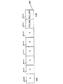
FIG. 5 shows the calculation of the timer start value t_TI. Shown is signal HALL, hall interrupt HN-1, HNEtc., timer interrupt TN-1, TNEtc., Hall length t_HN-1, T_HNEtc. The signal HALL is applied to the input terminal Hall (FIG. 2) of μC11. Hall length t_HN-1, T_HNIn the embodiment, etc. represent the time required for the four-
[0043]
The concepts of the hole length HL and the hole time t_H are used synonymously below. Hall time t_HN + 1Are each a hall interrupt HNIt does not include this later, and the subsequent hole interrupt HN + 1To finish including this. Hall interrupts and timer interrupts are numbered according to the hole time at which they occur. In other words, hall time t_HNHas a timer interrupt TN-At the end of this time-Hall interrupt HNBelongs to.
[0044]
In FIG. 5, the value of the timer CNT_HL is plotted below the signal HALL. The timer CNT_HL counts down between the respective values. For example, a time 310 from t_TI to 0 and a
[0045]
Hall time t_HN + 2The timer start value t_TI for the hole length t_H in this embodiment isNCalculated from This is shown symbolically at 300 and the hall time t_HN + 1The value t_TI is calculated according to the following formula:
t_TI: = t_HN-T_ZW (6)
That is, the hole length t_HNIs subtracted from the (constant) ignition angle time t_ZW. Similarly hall time t_HN + 3T_TI for the hole length t_HN + 1Calculated from This is shown symbolically at 301.
[0046]
In this way, time TN, TN + 1, TN + 2And so on. TNIs H for time t_ZWNIt is at an earlier point. That is, commutation is advanced. Similarly TN + 1Is HN + 1It is earlier. Time TN, TN + 1Etc. are indicated by arrows pointing up.
[0047]
Next, on the basis of FIGS. 19 to 21, how very advantageous the 4-
[0048]
6 and 7 show two possible cases that can occur when the hole length t_H is measured by the timer CNT_HL.
[0049]
Shown are the signal HALL and Hall interrupt H applied to the input terminal Hall (FIG. 2) of μC11.NAnd HN + 1, Timer interrupt TN + 1FIG. 7A shows the start value t_B and the stop value t_E of the timer CNT_HL on the time axis of FIG. 7A. These values are the next hall time t_HN + 2Hole length t_H executed for the first timeN + 1Used in the calculation of t_B is Hall interrupt H (explained earlier)NCorresponds to the start value t_TI of the timer CNT_HL at the time, t_E is the hole interrupt HN + 1This corresponds to the stop value of the timer CNT_HL at this time.
[0050]
Two cases can occur.
[0051]
In the first case (Fig. 6), the motor accelerates strongly and the hall interrupt HN + 1Occurs before the timer CNT_HL reaches the
[0052]
Hall length t_HN + 1Is calculated according to the following formula
t_HN + 1: = T_B−t_E + t_CORR (7)
Here, t_CORR is a correction value described in detail in S258 of FIG. 10, and is shown in FIG. 6B.
[0053]
In the second case (FIG. 7A), the timer CNT_HL has a hole interrupt HN + 1Reach 0 before the occurrence. When zero is reached, the timer interrupt T shown in FIG.N + 1Is triggered. Timer CNT_HL has timer interrupt TN + 1At the time, the value t_AR is automatically reloaded from the auto reload register AR (FIG. 1) and a new start is made. See S302 in FIG. t_B now has the same value as t_TI and therefore corresponds to t_AR.
[0054]
This is shown in FIG. 7B. HNT immediately afterN + 1Until the timer CNT_HL counts down from t_B to 0, the timer interrupt TN + 1Trigger. At the start of this interrupt, the timer CNT_HL is newly loaded with t_B, see FIG. 11, S302, and HN + 1Countdown a new time. In this case, however, the
[0055]
Timer interrupt TN + 1In the timer interrupt routine called by the occurrence of, commutation is executed as long as the ignition angle shift is applied. See FIG. 11, S318, S320, and S322. A flag KD (commutation execution) is set to 1. See FIG. 11, S324.
[0056]
Hall interrupt H following thisN + 1At this time, the timer CNT_HL is newly stopped and its end time t_E is stored. See FIG. 8A, S202. Hall length t_HN + 1(FIG. 7) is calculated in steps S254 and S258 of FIG. 10 based on the set flag KD (FIG. 10, S252) as follows:
t_1: = t_B−t_E (8)
t_HN + 1= T_B + t_1 + t_CORR (9)
[0057]
Here, t_1 is a timer interrupt T as shown in FIG.N + 1And hall interruption HN + 1Is the time between. Hall length t_HN + 1To calculate the value t_B to the value t_1. Because timer CNT_HL is hole interrupt HNAnd timer interrupt TN + 1This is because this value is counted down to zero. Further, for example, a correction value t_CORR which is 40 μs, for example, is added. This is illustrated in FIG. 7B and will be described in more detail later in FIG. 10, S258. Hall interruption HN + 1After the rotation speed calculation (S274 in FIG. 10), the flag KD must be reset again (KD: = 0, see S272 in FIG. 10).
[0058]
Numerical example for FIG.
HNThen the timer CNT_HL is set to the value t_TI = t_B = 9800 (previously calculated in
t_1: = 9800-9640 = 160 μs
t_HN + 1: = 9800 + 160 + 40 = 10000 μs
Therefore, the hole length t_HN + 1Is a length of 10,000 μs in this example, and n_i = 15000000 / t_HN + 1= 15000000/10000 = 1, corresponding to the number of revolutions of 1500 revolutions / minute (
[0059]
Then HN + 1Immediately after, a new value t_B ′ is loaded into the timer CNT_HL. This value corresponds to the value t_TI '(previously calculated). See
[0060]
8A and 9B show a flowchart of an advantageous embodiment of an advantageous hole interrupt routine. That is, it is a flowchart of an interrupt routine depending on the rotor position. This interrupt routine is triggered when the predetermined rotor position is reached, and the hole length t_HNDetection is performed. Further, when commutation is not executed in the timer interrupt routine, commutation is also executed. All of the registers and variables described later are 16 bits in size in the embodiment.
[0061]
In S302, the timer CNT_HL is stopped, and the stop time of the timer CNT_HL is stored in t_E.
[0062]
In subsequent steps S204 to S208, the edge for the next hole interrupt is adjusted by μC11. For this purpose, in S204, it is checked whether HALL = 1. If it is 1, in S206, the edge to be triggered by the next hole interrupt is set to the falling edge (HIGH → LOW). Otherwise, in S208, the edge is set to the rising edge (LOW → HIGH).
[0063]
In the next S210, two cases are distinguished on the basis of the flag DE (revolution speed reached):
If DE = 1, no timer interrupt occurs or a timer interrupt occurs and an ignition angle shift is applied. Both are signs that the motor has reached its speed, as will be explained in detail later.
-If DE = 0, the ignition angle shift is interrupted (SZW = 0) and a timer interrupt has occurred. As will be described later, this is a sign that the minimum rotational speed n_min at which the ignition angle shift is applied has not yet been reached.
[0064]
For DE = 0, commutation is executed and the timer CNT_HL is set to a fixed value t_max (maximum hole length). This fixed value corresponds to the minimum rotation speed n_min. For example, if the minimum number of revolutions is 300 revolutions / minute, according to equation (4)
t_max = 15000000/300 = 50000 μs
It is.
[0065]
For this reason, OUT1 and OUT2 are set to 0 in S312.
[0066]
In S214, the auto reload register AR and the counter CNT_HL are set to t_max (for example, 50000). The timer CNT_HL operates with a resolution of 1 μs in this embodiment. Setting CNT_HL to a length of 50000 μs corresponds to a rotation speed of 300 rotations / minute. Based on this, the timer CNT_HL is started.
[0067]
A flag DE (which was 0) is set to 1 in S216, and commutation is executed in S218 to S222. If HALL = 1 in S218, OUT1 is set to HIGH in S220, and OUT2 is set to HIGH in S222 otherwise. The program requires a certain amount of time for program steps S214-S218 to be executed between the switch-off of ports OUT1 and OUT2 at S212 and the switch-on of OUT1 through OUT2 at S220 through S222. Therefore, a sufficient commutation gap (FIG. 23: t_G) is maintained. This is, for example, 50 μs.
[0068]
In step S224, the hall interruption is left.
[0069]
When DE = 1 in S210, calculation of the hole length t_H and a new timer value t_TI is required for the ignition angle shift in S230. The main program is formed by a function manager, which will be described in detail with reference to FIG. The function manager requests a routine by setting a flag and releases the request by resetting the flag. A flag FCT_ZWV is set to 1 in S230 to request a calculation.
[0070]
In another possible embodiment for S230, the calculation is performed directly in the hole interrupt routine (FIG. 8). This is indicated by S232. If the calculation is performed in S232, the hole time t_HN(Eg t_HFive) For the calculation of the timer interruption time t_TI belonging toN-1(Eg t_HFour) Can be used. If S230 is used, the hall time t_HN-2(Eg t_HThree) Or an earlier Hall time is used as shown in FIGS. If the calculation is performed with a hole interrupt (S232), S230 is omitted. The following description relates to an embodiment without S232.
[0071]
In S234 (FIG. 9B), it is checked whether or not the flag KD = 1 (KD = commutation execution). When KD = 1, a timer interrupt has occurred within the hall time belonging to the hall interrupt (H in FIG. 7A).N + 1And an ignition angle shift is applied. In this case, the commutation is already a timer interrupt (T in FIG.N + 1) And jump directly to S238.
[0072]
If KD = 0 in S234, a timer interrupt has not occurred within the hall time belonging to the hall interrupt. That is, the situation in FIG. The commutation gap (t_G in FIG. 23) is started by setting the two ports OUT1 and OUT2 to zero in S236. That is, no energy is supplied to the stator winding 38 (FIG. 1) for a short time. However, if a timer interrupt has occurred but the ignition angle shift has not been commutated because the ignition angle shift is inactive, this is taken into account in the branch under S210 for DE = 0 (FIG. 8A).
[0073]
In S238, the value t_TI calculated by the ignition angle calculation (FIG. 10 or FIG. 21) described later is loaded into the auto reload register AR and the timer CNT_HL, and the timer CNT_HL is started.
[0074]
In S240, the ignition angle shift is set to active by setting the flag SZW: = 1. This is because in this case, for example, the required number of revolutions of 300 revolutions / minute has been reached.
[0075]
In S242, it is again checked whether or not commutation has already been performed based on the flag KD (commutation execution). If not (KD = 0), based on the signal HALL in S244, it is checked whether OUT1 is set HIGH in S246 or whether OUT2 is set HIGH in S248. Here, the commutation gap (t_G in FIG. 23) is formed between the switch-off (S236) of the ports OUT1 and OUT2 and the switch-on in steps S238 to S244.
[0076]
In S250, the hall interruption routine is left.
[0077]
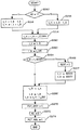
FIG. 10 shows a flowchart of an exemplary routine for calculating the ignition angle. This ignition angle calculation is requested by setting the request bit FCT_ZWV (FIG. 17) in each hall interrupt routine (FIG. 8) when the minimum rotational speed is reached. See S230 of FIG. 8A. The ignition angle calculation is invoked by the function manager 190 (FIG. 17) when a relatively high priority task is not required. Therefore, it cannot be said exactly when this calculation is performed. Therefore, when the ignition angle calculation is performed BN(For example, FIGS. 13A and 14B) are not set accurately and show example time points.
[0078]
It should be noted that the calculation of the hole length t_H always applies to the previous hole time. For example, hall time t_HNDuring the hole length t_HN-1Is calculated.
[0079]
In S252, a timer interrupt (for example, T in FIG.N + 1) To check whether or not commutation has been executed. See S234 in FIG. 9B. If affirmative (KD = 1), according to S254, the hole length t_H is obtained from the start time t_B and the time t_1 as shown in FIG. 7 and described therein. This time t_1 is the difference between t_B and t_E. In the negative case (KD = 0), according to S256, the hole length t_H is obtained from the difference between t_B and t_E. See FIG.
[0080]
In S258, the correction time t_CORR is added to the hole length t_H. This is done by stopping timer CNT_HL at S202 at the start of the hole interrupt (FIGS. 8A and 9B) and then starting for the first time at S232. By then, the hole interrupt routine needs a predetermined time added as t_CORR (eg, 40 μs) to obtain an accurate hole length t_H in S258.
[0081]
In S260, the instantaneous hole length t_H is stored in the actual hole value t_i. Thereby, the instantaneous actual Hall value is used as a measure for the instantaneous rotational speed in all other program parts (eg control).
[0082]
In S262, the instantaneous start time of the timer CNT_HL is stored in t_B. This time can then be used in the next hole time for the calculation of t_TI.
[0083]
An inspection of the rotational speed is performed. This is because, for example, the ignition angle shift should be executed from a predetermined minimum number of revolutions of 300 revolutions / minute. For this purpose, in S264, it is compared whether t_H> t_SZW. t_SZW (for example, 49664 μs, which corresponds to 0 × C200) is the maximum hole length until the ignition angle shift is to be performed. If t_H is greater than t_SZW, the motor is too slow, and the ignition angle shift is interrupted by SZW: = 0 in S266.
[0084]
In S268, a commutation time point t_TI, that is, a time point at which a timer interrupt should be triggered is calculated. For this purpose, the value t_ZW, that is, the time at which the commutation time should be shifted early is subtracted in S268. This time is, for example, 200 μs. This value may be constant or a value depending on the motor parameter. This value t_ZW can be changed from the outside via the bus 30 (FIG. 16). If t_ZW = 0, the ignition angle shift is cut off.
[0085]
Next, an ignition angle calculation routine is processed. The request bit FCT_ZWV (FIG. 17) is set to 0 in S270, and the flag KD is set to 0 again in S272. As a result, the subsequent hall time can be used, and the motor control request bit FCT_RGL (FIG. 17) is set in S274, thereby requesting motor control.
[0086]
Therefore, the main tasks of the ignition angle calculation routine of FIG. 10 are detection of the duration of the preceding hole length (S258), calculation of the commutation time for the subsequent hole time (S268), and request for control (S274).
[0087]
FIG. 11 shows a flowchart for an exemplary timer interrupt. This timer interrupt is used for motor control and is triggered when the timer CNT_HL started and initialized with the preceding hole interrupt counts down to 0 before the next hole interrupt is triggered. See FIGS. 7A and 7B.
[0088]
When the
[0089]
In S304, it is inspected based on the flag SZW whether or not the ignition angle shift is active. If it is not active, the motor is rotating slower than the minimum speed. This becomes clear when the auto-reload register AR and the timer CNT_HL correspond to the minimum rotation speed n_min in S214 of the hole interrupt routine if the ignition angle shift is not active when the timer interrupt is performed. This is because it is set to t_max. Nevertheless, a timer interrupt (T in FIG.N + 1) Is the hole interrupt (H in Fig. 7)N + 1) Does not reach the minimum rotational speed n_min, the flag DE (reach the rotational speed) is set to 0, and the timer interrupt routine is exited in S308.
[0090]
If the ignition angle shift is active (SZW = 1), the process jumps from S304 to S310. Here, the two ports OUT1 and OUT2 are set to 0 at the start of the commutation gap.
[0091]
Steps S312 to S316 form a program loop that generates a sufficiently long commutation gap (t_G in FIG. 23). For this reason, the delay value t_DEL is assigned to the timer DEL_CNT in S312. This is, for example,
[0092]
If not, the process jumps again to S314 and the loop is continued. If, for example, 10 μs is required to pass through the loop, a delay of 50 μs is obtained with the values mentioned above, during which both ports OUT1 and OUT2 have an output signal of zero. This affects the commutation gap t_G.
[0093]
Subsequently, as usual, commutation is performed as described in S218 to S224 of FIG. 8A. If the hall value HALL = 1 in S318, OUT1 is set to HIGH in S320, otherwise OUT2 is set to HIGH in S322. Therefore, commutation is performed by a timer interruption, that is, before a hall interruption, by an ignition angle shift. This is hall interrupt H in FIG.N + 1Time T beforeN + 1It is.
[0094]
In S324, the flag KD (commutation execution) is set to 1, so that the hole interrupt and ignition angle calculation routine can be identified, and based on this, the hole interrupt routine is terminated in S326.
[0095]
FIG. 12 shows, as an example, signal HALL and hall interrupt H when the motor of the present invention is started.NAnd timer interrupt TNIndicates the time point. Hall time t_HNAre each a hall interrupt HN-1And HNIt is the time between and becomes gradually shorter. This is because the motor accelerates. No timer interrupt occurs during each hall time. In this example, t_H2And the ignition time calculation is performed at the subsequent hall time, but in this example based on the acceleration of the motor, the timer interrupt T1, TTenAnd T11Only occurs. Because the rotation speed is t_H8This is because it becomes constant to some extent for the first time.
[0096]
13 (A) and 14 (B) show the process of FIG. 12 on an enlarged scale, with additional explanation.
[0097]
FIGS. 13A and 14B show by way of example the time course when the motor of the present invention is started. This process reveals the relationship between hole interruption, ignition angle calculation and timer interruption.
[0098]
The following variables are used in FIGS. 13A and 14B:
DE: Flag “revolution reached”
KD: Flag "Execute commutation"
SZW: Flag “Start ignition angle shift”
t_AR: value of auto-reload register AR (Fig. 1)
CNT_HL: Timer for timer interrupt and hole length calculation
t_E: Stop time (end time)
t_H: Hall length (Hall time)
t_B: Start time (start time)
OUT1: μC11 port for motor energization
OUT2: μC11 port for motor energization
[0099]
The signal HALL on the input side of μC11 is plotted. The hole length t_H is between the hole interrupts surrounding the hole length t_H, for example, t_H2= 40ms is H1And H2T_HThree= 35ms is H2And HThreeBetween. Hall interruptions are each HNTherefore, the timer interrupt is TNAnd the execution of the ignition angle calculation is BNIs indicated by Where N is the hall interrupt to which it belongs t_HNIs the index.
[0100]
There are several important variables under the signal HALL. These variables are used in the program executed by μC11. The time display is shown in ms for space reasons, but is processed in μs time inside the program. At the start of the motor, several variables are initialized (column INIT). t_TI and t_B are initialized by 50 ms. This corresponds to a rotational speed of 300 revolutions per minute, and the ignition angle shift is applied in this embodiment for the first time from this rotational speed. DE and KD are set to zero. This is because the required number of revolutions has not yet been reached. SZW is also initialized by 0. This is because the ignition angle shift is cut off.
[0101]
1st hall interrupt H0Thus, 50 ms is loaded into the auto reload register AR and the timer CNT_HL for the first time, and the timer CNT_HL is started. Hall length t_H1Is 60 ms, so timer interrupt T1Is hall interruption H1Occurs before.
[0102]
Since the ignition angle shift is interrupted (SZW = 0), only one value DE is set to 0 in the timer interrupt routine (S306 in FIG. 11). This indicates to the hall interrupt that the motor has not yet reached the minimum speed n_min. Because hall length t_H1Is larger than the maximum hole length t_max corresponding to the minimum rotation speed n_min. The timer CNT_HL is automatically loaded with an auto-reload value t_AR of 50 ms and starts.
[0103]
Hall interruption H1The hall interrupt routine (FIG. 8) is called. A stop time t_E of 40 ms is ensured. This stop time is the timer interrupt T when the timer CNT_HL is newly set to 50 ms.1And hall interruption H1This occurs when 10 ms elapses between Since DE = 0, commutation is at time H1And 50 ms is loaded into t_AR and CNT_HL, and timer CNT_HL is started. DE is set to 1. No calculation is required.
[0104]
Hall length t_H2During this period, the motor reaches an average speed of 300 rpm for the first time. Therefore, the hall interrupt H before the timer CNT_HL counts down to zero.2Is triggered. Therefore, timer interrupt T2Does not occur.
[0105]
Hall change H2In the hole interruption routine at this time, a 10 ms stop time t_E of the timer CNT_HL is secured. DE is the hole length t_H2Since no timer interrupt occurred during this period, the value DE = 1 is held. This identifies that the hall interrupt routine has exceeded 300 rpm. In the hall interruption routine, an ignition angle calculation routine (FIG. 10) is required, and the ignition angle shift is activated by SZW: = 1. Hall length t_H2Has not been commuted yet (KD = 0), so the commutation is at time H during the hole interrupt routine.2Is executed. The auto-reload register AR and the timer CNT_HL are loaded with the value t_TI initialized to 50 when the motor is started. This is because the ignition angle calculation has not been executed yet. Then, the timer CNT_HL is newly started.
[0106]
Hall length t_HThreeDuring this time, the ignition angle shift is calculated for the first time. No timer interrupt has occurred (KD = 0), so the hole length t_HThreeHole length t_H calculated during2Arises from t_B = 50 ms and t_E = 40 ms. From this point, when the ignition angle shift time is t_ZW = 0.2 ms, a timer interruption time of 39.8 ms occurs. Hall time t_HThreeThe timer start time is secured at t_B.
[0107]
Hall interruption HThreeThe hall interrupt routine up to2Elapses in the same manner as in the hall interrupt routine. This is because the motor further accelerates and the hole interrupt occurs before the timer CNT_HL reaches the
[0108]
Hall time t_H8Thus, the motor finally reaches the target rotational speed of 1500 revolutions / minute. This rotational speed corresponds to a hole length of 10 ms. In this embodiment, the hall time t_HNTimer interrupt time t_TI for is always the hall time t_HN-1During the hole length t_HN-2Since there are two hole time “lags”, That is, the first hole time when the timer CNT_HL is started by the correct timer interrupt time t_TI is t_HTenIt is. Because hall time t_H8Because the first hole time of 10 ms, t_H8The result from the hole length calculation of the hole time is t_HTenIt is because it is used for the first time.
[0109]
Hall time t_HTenDuring the calculation of the ignition angle BTenIs executed again. The start value t_TI for the auto-reload register AR and the timer CNT_HL is H9It was 9.8 ms during the hall interrupt routine.
[0110]
Therefore, hall interruption H9Timer interrupt T after 9.8msTenMust be triggered. The timer CNT_HL is automatically loaded with the value t_AR (9.8 ms) and is newly started. The ignition angle shift is turned on (SZW = 1). As a result, the timer interrupt (T10). Flag KD is set to 1, which causes HTenInstructs that commutation has been performed for the subsequent hole interruption routine and ignition angle calculation.
[0111]
Hall interruption HTenIn the hole interrupt routine at, the stop value of the timer CNT_HL is secured at t_E, the ignition angle calculation routine is requested, the auto reload register AR and the timer CNT_HL are loaded, and the timer CNT_HL is started. Commutation is already done by the timer interrupt routine.TenSince it is done at the time of, will not be further commutated.
[0112]
Subsequent hall time t_H11Etc., as long as the actual rotational speed or the target rotational speed of the motor does not change, t_HTenElapsed in the same way.
[0113]
Motor control
FIG. 15 shows the circuit parts important for motor control and drive. The same members as those in the previous drawings or the members acting in the same way are denoted by the same reference numerals and are not usually described again.
[0114]
The terminal assignment of μC11 is shown in FIG. The output terminals OUT1 and OUT2 of the μC11 control the
[0115]
The output terminal RGL of the
[0116]
If
[0117]
A triangular signal formed by the
[0118]
For the operation of the
[0119]
When the voltage of the triangular signal at the inverting input terminal of the
[0120]
The so-called duty ratio is adjusted via the voltage of the
[0121]
In order to be able to start the motor when switched on, the
[0122]
The current limiting
[0123]
When the potential at 149 reaches a predetermined value,
[0124]
The current limiting
[0125]
For other forms of the current limiting part, refer to DE 19826458.5 (Intern: D215). This current limiter can be formed by a comparator and can be controlled by a program.
[0126]
EEPROM function
FIG. 16 shows a part of a circuit related to the
[0127]
The
[0128]
The write protection input terminal WP of the
[0129]
Therefore, the lines ESDA and ESCL are serial buses between the
[0130]
Normally, the
[0131]
The
[0132]
Further, the
[0133]
The circuit having the
[0134]
For further description of the
[0135]
A value in the
[0136]
Function manager
FIG. 17 shows a flow chart according to a possible embodiment of the whole program executed in μC11. After the fan is switched on, an internal reset is triggered at μC11. In step S600, μC11 is initialized. For example, the parameters are transmitted from the
[0137]
After initialization, jump to the
[0138]
First, the functions that are critical in time and must be processed during each loop execution are processed. This belongs to the commutation function COMM in S602. This is because the IIC bus (FIG. 16) must be inspected every 250 μs, for example, at a baud rate of 2k.
[0139]
FIG. 18 shows an
[0140]
In this embodiment, the
Bit 1: FCT_ZWV for the ignition angle calculation routine
Bit 2: FCT_RGL for any type of control routine.
[0141]
The remaining bits are reserved for additional requestable functions that can be added to the
[0142]
When a predetermined requestable function is requested by another function or interrupt routine, the bit of the function to be requested is set. The function is executed if the
[0143]
If the requested function is processed, this sets its bit (FIG. 18) to 0 again. For example, FCT_RGL: = 0.
[0144]
In FIG. 17, after S602, starting from the most important requestable function in a predetermined order, it is checked whether or not those request bits are set. If this is a function, the function is executed, and based on this, the process jumps again to the start S602 of the
[0145]
The processing time of the called function must not exceed the maximum allowable time between two queries on the
[0146]
In S610, it is checked whether the request bit FCT_ZWV for the ignition angle shift is set, that is, whether it has the
[0147]
If FCT_ZWV is not set in S610, it is checked in S614 whether FCT_RGL is set. If it is set, a control routine for controlling the motor speed is called in S618.
[0148]
If the bit to be checked is not set in either S610 or S614, the process jumps to S602 again, and a function executed at the time of executing each loop of the
[0149]
FIG. 17 symbolically shows a hole interrupt at 620. This hole interrupt has the highest priority L1 (level 1). The hall interrupt has this high priority because accurate detection of the hall signal is very important for quiet rotation of the
[0150]
A timer interrupt is shown at 622 below the hole interrupt. This timer interrupt has a lower priority L2 and interrupts all processes below it as indicated by
[0151]
When hall interrupts and timer interrupts are requested simultaneously, they are processed according to their priority order.
[0152]
The function COMM has the next lowest priority L3. This is because data must not be lost via the
[0153]
Function ZWV has the next lowest priority L4. This function can be requested at S230 and is illustrated in FIG. 10 (or FIG. 21).
[0154]
It is the function RGL (S614) that has the lowest priority. This is because the rotational speed of the motor usually changes slowly due to its mechanical inertia, so the control function is usually not critical in time. However, the order of steps S610 and S614, and therefore their priorities, can be interchanged.
[0155]
In this way, the various “needs” of the
[0156]
Ignition angle shift in consideration of magnetization error of
FIG. 19 shows a four-pole
[0157]
Due to the inhomogeneity of the magnetized material and the inevitable errors (not shown) in the magnetizer, the course of the magnetic flux density is not precisely defined, especially in the transition regions 530-533, and varies slightly from rotor to rotor.
[0158]
Assuming that the
[0159]
The
[0160]
Portion 536 'is generated by
[0161]
Portion 537 'is generated by
[0162]
FIG. 20B shows the associated signal HALL. This signal reflects the magnetization error just described. That is, the
[0163]
[0164]
If the
[0165]
If the
[0166]
This leads to irregular rotation of the motor and increases motor noise.
[0167]
Therefore, according to the invention, the hole length of the part of the signal HALL is advantageously used for the calculation of the time t_TI for the part after one rotor rotation. This is illustrated symbolically by way of example for a four pole rotor by
[0168]
FIG. 21 shows an ignition angle calculation routine that is changed correspondingly to commutation by ignition angle shift. Here, as described above, the magnetization error of the
[0169]
In step 268 ', instead of the direct calculation of the timer start value t_TI (see S268 in FIG. 10), two variables t_4 and t_3 are additionally used to intermediately store the calculated timer start value t_TI. Subsequent hall time t_HNThe timer start value t_TI used for the hole length t_HN-4The timer start value t_4 calculated from the above is assigned.
[0170]
The calculated timer start value is then shifted so that this timer start value becomes the correct variable for the next ignition angle calculation. Hall length t_HN-3The value t_3 calculated from is shifted after t_4, and the timer start value (t_H-t_ZW) calculated by the instantaneous ignition angle calculation is stored in t_3 (where t_H is the hole length t_H)N-2Is).
[0171]
Further, step S267 is newly inserted. The memory variables t_4 and t_3 are set to the value 50000 when the ignition angle shift is interrupted (S266: SZW: = 0), so that this variable has a unique state.
[0172]
FIG. 22 shows an example of a hole interruption routine for the commutation of the present invention when the ignition angle shift is not performed. This is similar to that shown in FIG. At the time of each hole interrupt (Y in FIG. 4), the program just being executed is interrupted, the so-called environment (for example, the stack pointer and the register) of the
[0173]
In this embodiment, a 16-bit timer CNT_HL is similarly used for measuring the hole length HL (FIG. 4). This timer starts from a predetermined start value and continuously counts down. When it reaches 0, it jumps back to its maximum value if counting continues. In this way, it operates like a ring counter. This timer is also a component of μC11. The hole length HL can be used here for speed control.
[0174]
In S702, the actual hole length HL (see FIG. 4) is detected. The actual timer value t_E (FIG. 4) is read from the timer CNT_HL and the hole length HL is calculated by subtraction of the stored “old” timer value t_O (FIG. 4: at the time of the preceding timer interrupt Y). For this purpose, t_E−t_O is calculated and a double complement (Zweierkomplement) is formed from the result. In this way, the correct count difference is always obtained when the timer does not pass more than half of its maximum value.
[0175]
Based on this, the instantaneous timer value t_E is stored in t_O (S702). The resolution of the timer CNT_HL used in this embodiment is 1 μs, and therefore the hole length HL exists in units of μs.
[0176]
For example, if t_O = 45000 and t_E = 35000, the hole length HL = (45000-35000) = 10000 is obtained, which corresponds to 10000 μs.
[0177]
In the next step, commutation is performed. In S704, it is checked whether HALL = 1 (HIGH). If HALL = 1, OUT2 is set to LOW in S710. Since OUT1 and OUT2 are now LOW, a temporal commutation gap is inserted in S712. This is to avoid a short circuit in the
[0178]
If HALL = 0 (LOW) in S704, the opposite commutation is similarly performed in S720, S722, and S724, and HALL_INT is set opposite in S726. In S730, the hole interruption routine is exited according to FIG.
[0179]
FIG. 23 schematically shows a commutation process when n> 300 rotations / minute, for example, 2000 rotations / minute. Therefore, in this case, an ignition angle shift is performed.
[0180]
FIG. 23A shows the rotor position signal HALL. This signal is at position HN, HN + 1, HN + 2Triggers an interrupt (FIG. 8) depending on the rotor position. That is, the hole interrupt is output at Y in FIG.
[0181]
Hall interruption HNStarting from, the time t_TI is measured by the timer CNT_HL. This time is calculated from the values t_HN and t_ZW according to equation (6). The value t_ZW can be changed via the
[0182]
Time TN + 1The timer CNT_HL reaches the
[0183]
According to S310 of FIG.N + 1Both OUT2 (FIG. 21B) and OUT1 (FIG. 21C) are zeroed. That is, winding 38 is decoupled from the current supply, and after commutation gap t_G, signal OUT1 is set HIGH at S322 (acted by program steps S312, S314, S316). This is because HALL = 1. On the other hand, OUT2 remains LOW as stored in step S310. OUT1 = HIGH means that the
[0184]
At the same time TN + 2Thus, the two signals OUT1 and OUT2 are set to LOW in step S310 of the routine of FIG. Then, after the commutation gap t_G, the value OUT2 is set to HIGH. This is because HALL = 0. See steps S318 and S322 in FIG. In contrast, OUT1 remains at the value LOW stored in step S310. In this way, the
[0185]
FIG. 24 shows the signal HALL at the bottom and the current i_M of the single stator winding 38 at the top. In FIG. 24, the ignition angle shift is interrupted. That is, t_ZW = 0. After commutation, time HNIt can be seen that the current i_M changes slowly due to (change in the signal HALL). This current thus only reaches a small amplitude in this case, ie the output produced by the motor M is low.
[0186]
FIG. 25 also shows the signal HALL at the bottom and the current i_M (FIG. 1) at the top. However, in this case, early commutation (early ignition) is performed. That is, the current i_M is the hole change H for the time t_ZW.NBe more commutated. It is clear that the current i_M changes very quickly immediately after commutation and reaches a much larger amplitude than in the case of FIG. That is, the motor M in this case produces a relatively large output and can therefore reach a relatively high rotational speed. In the case of FIG. 25, the commutation is advanced about 15 ° el from the change of the signal HALL.
[0187]
A typical example for the component values used is shown in the table:
Capacitor:
135 1.5nF
127,152 10nF
99,110,166,167 33nF
154 100nF
Tantalum capacitor 3.3μF
resistance:
140 3Ω
162, 163 47Ω
153,155 1kΩ
133,136 2.2kΩ
106 3.3kΩ
164, 165 4.7 kΩ
123, 131, 132 10kΩ
172, 173 22kΩ
114,126 33kΩ
134 47kΩ
101, 112, 128, 169 100 kΩ
EEPROM26 2-Wire Serial CMOS EEPROM
AT24C01 (ATEMEL)
(Nat. Semicond.)
[Brief description of the drawings]
FIG. 1 is an overview diagram as an example of an embodiment of the present invention.
FIG. 2 is a pin array diagram of μC COP842CJ.
FIG. 3 is a circuit diagram showing components for processing a Hall signal.
FIG. 4 is a diagram of a Hall signal and commutation when ignition angle shift is not performed.
FIG. 5 shows an (early) commutation time T based on a value derived from the signal HALL.NIt is the schematic for demonstrating performing this calculation.
6A and 6B are diagrams showing the calculation of the hole length when the timer interrupt is not performed.
FIGS. 7A and 7B are diagrams showing the calculation of hole length when a timer interrupt is present.
FIG. 8 (A) is a flowchart of a hole interruption routine by the ignition angle shift together with FIG. 9 (B).
FIG. 9B is a flowchart of a hole interruption routine by ignition angle shift following FIG. 8A.
FIG. 10 is a flowchart of an ignition angle calculation routine.
FIG. 11 is a flowchart of a timer interrupt routine based on ignition angle calculation.
FIG. 12 is a diagram of a hall signal at the time of starting a motor.
FIG. 13A is a diagram showing the hall signal and the variable to which the drive function belongs together with FIG. 14B.
FIG. 14B is a diagram illustrating the hall signal and the variable to which the drive function belongs, following FIG. 13A.
FIG. 15 is a circuit diagram showing a part important for control and drive of an electronic commutation motor.
FIG. 16 is a circuit diagram showing important parts for EEPROM control and data connection via the
FIG. 17 is a schematic diagram of an advantageous embodiment of a function manager.
FIG. 18 is a schematic diagram of a function register used in the function manager.
FIG. 19 is a schematic view of a permanent magnet of a 4-pole outer rotor.
20A and 20B are schematic views for explaining the action of the magnetization error of the outer rotor of FIG.
FIG. 21 is a flowchart of ignition angle calculation similar to FIG. 10 but modified to an advantageous form.
FIG. 22 is a flowchart of a hole interrupt routine for commutation as shown in FIG.
FIG. 23 is a schematic diagram of a commutation process when the commutation time point is electronically shifted early.
FIG. 24 is a diagram showing the time lapse of the signal HALL and the motor winding current i_M, and here, the commutation point is not shifted in the early direction.
FIG. 25 is a diagram showing the time lapse of the signal HALL and the motor winding current i_M, and here, the commutation time is shifted in the early direction.
Claims (12)
ロータは、モータ作動時、複数のコミュテーション角度領域を通過して回転し、該角度領域の各々においてロータが当該各角度領域を通過するとき1つのコミュテーションが行われ、
各コミュテーションの前に以下が実行される:
a)当該コミュテーションが実行されるべき関連付けられた以降のコミュテーション角度領域と所与の角度関係を有する測定角度領域を通過するロータの回転、その際、ロータが該領域を通過して回転するのに必要な持続時間(t_H)に関する測定角度領域データが検出される;
b)前記持続時間(t_H)から数値(t_ZW)を減算することにより第1時間間隔(t_TI)が計算される計算領域を通過するロータの回転、但し、該数値はコミュテーションの所望の進角時間の大きさによって決定される;
c)前記第1時間間隔(t_TI)に対応する時間が測定される時間測定ステップ、該ステップは前記関連付けられたコミュテーション角度領域に関連付けられたロータの所与の角度方向に開始する;
d)前記時間測定ステップの終了の際にトリガされる割込ルーチン、該割込ルーチンは、モータが定常状態で作動しているとき、前記関連付けられたコミュテーション角度領域の間に、時間進角されたコミュテーションを制御するよう作用する。 An electronic commutation motor having a stator, a rotor (39) and a program-controlled microprocessor or microcontroller (11) (hereinafter referred to as a microprocessor) used to control the commutation of the motor. ,
When the motor operates, the rotor rotates through a plurality of commutation angle regions, and one commutation is performed when the rotor passes through each angle region in each of the angle regions,
Before each commutation:
a) rotation of the rotor through a measurement angle region having a given angular relationship with the associated subsequent commutation angle region in which the commutation is to be performed, in which case the rotor rotates through that region Measuring angular region data relating to the duration (t_H) required for
b) Rotation of the rotor through the calculation area where the first time interval (t_TI) is calculated by subtracting a numerical value (t_ZW) from the duration (t_H), where the numerical value is the desired advance of the commutation Determined by the amount of time;
c) a time measurement step in which a time corresponding to the first time interval (t_TI) is measured, the step starting in a given angular direction of the rotor associated with the associated commutation angle region;
d) an interrupt routine that is triggered at the end of the time measurement step, the interrupt routine being a time advance angle during the associated commutation angle region when the motor is operating in steady state. Acts to control the commutation performed.
請求項1に記載のモータ。The motor control interrupt routine is activated when the first time interval (t_TI), which depends on the detected duration, is greater than the time actually required for the rotor to pass a given angular path. Including program steps to prevent
The motor according to claim 1.
請求項2に記載のモータ。Further comprising an apparatus for triggering a rotor position dependent interrupt routine at a given rotor position;
The motor according to claim 2.
請求項3に記載のモータ。In order to detect the duration (t_H), a timer that can be controlled by a rotor position dependent interrupt routine is provided.
The motor according to claim 3.
請求項4に記載のモータ。The timer is also configured to trigger the motor control interrupt routine.
The motor according to claim 4.
前記所与の第1計数値を計数した後、モータ制御割込が実行される、
請求項5に記載のモータ。The timer can be loaded during a rotor position dependent interrupt with a given first count value, which is counted at a first time interval (t_TI) depending on the detected duration. Correspondingly,
After counting the given first count value, a motor control interrupt is executed.
The motor according to claim 5.
請求項3に記載のモータ。The rotor position dependent interrupt has a higher priority than the motor control interrupt,
The motor according to claim 3.
当該ロード過程に続いて次のロータ位置依存割込まで計数を行うことにより、所与の計数値と次のロータ位置依存割込に達した際のタイマ値との差を形成することによって、これらの割込過程間の時間差を検出する、
請求項4に記載のモータ。The timer that generates a timer value when activated can be loaded with a given count value during a motor control interrupt;
By counting at the next rotor position dependent interrupt following the loading process, these are formed by forming the difference between the given count value and the timer value when the next rotor position dependent interrupt is reached. To detect the time difference between the interruption processes of
The motor according to claim 4.
該オートリロードレジスタは、所与の第1計数値を記憶し、該計数値をモータ制御割込の間に所与の計数値としてタイマに供給する、
請求項8に記載のモータ。Further includes an auto reload register to load a given count value;
The auto reload register stores a given first count value and supplies the count value to a timer as a given count value during a motor control interrupt.
The motor according to claim 8.
前記ロータ位置発生器の出力信号は、マイクロプロセッサ(11)による評価のために、該マイクロプロセッサの割込能力のある入力端子に供給され、該マイクロプロセッサで処理され、
マイクロプロセッサの少なくとも1つの出力端子にて、ロータ位置発生器(40,41)の信号に対してシフト時間だけシフトされた制御信号(OUT1、OUT2)をモータの時間進角されたコミュテーションのために送出し、
前記シフト時間の持続時間は回転数の所与の関数であり、
マイクロコントローラ(11)は割込能力のあるタイマ(CNT_HL)を少なくとも1つ有し、
該タイマによって、制御信号の出力として機能するマイクロプロセッサの少なくとも1つの出力を制御する、
ことを特徴とする電子コミュテーション式モータ。Stator (38), rotor (39), program-controlled microprocessor or microcontroller (11) (hereinafter referred to as microprocessor) used to control commutation of motor (M), rotor position An electronic commutation motor having a generator (40, 41),
The output signal of the rotor position generator is supplied to an interrupt-capable input terminal of the microprocessor for evaluation by the microprocessor (11), and is processed by the microprocessor.
Control commutation (OUT1, OUT2) shifted by the shift time with respect to the signal of the rotor position generator (40, 41) at at least one output terminal of the microprocessor for time-advanced commutation of the motor To
The duration of the shift time is a given function of the rotational speed;
The microcontroller (11) has at least one timer (CNT_HL) capable of interrupting,
The timer controls at least one output of the microprocessor that functions as the output of the control signal.
An electronic commutation motor characterized by that.
請求項10記載の電子コミュテーション式モータ。The timer (CNT_HL) is automatically postloaded with a value (t_AR) during a given state, and the timer is newly started.
The electronic commutation motor according to claim 10.
当該モータにおいてはタイマ(CNT_HL)と割込がホール長(HL)の測定に使用される、請求項10または11記載の電子コミュテーション式モータ。The microprocessor triggers an interrupt on each change of the signal (HALL) of the rotor position generator (40, 41),
The electronic commutation motor according to claim 10 or 11, wherein a timer (CNT_HL) and an interrupt are used for measuring a hole length (HL) in the motor.
Applications Claiming Priority (3)
| Application Number | Priority Date | Filing Date | Title |
|---|---|---|---|
| DE19845626.3 | 1998-10-05 | ||
| DE19845626A DE19845626A1 (en) | 1998-10-05 | 1998-10-05 | Electronically commutated motor |
| PCT/EP1999/005282 WO2000021189A1 (en) | 1998-10-05 | 1999-07-23 | Electronically commutated motor |
Publications (3)
| Publication Number | Publication Date |
|---|---|
| JP2002528029A JP2002528029A (en) | 2002-08-27 |
| JP2002528029A5 JP2002528029A5 (en) | 2006-08-31 |
| JP4618890B2 true JP4618890B2 (en) | 2011-01-26 |
Family
ID=7883319
Family Applications (1)
| Application Number | Title | Priority Date | Filing Date |
|---|---|---|---|
| JP2000575211A Expired - Fee Related JP4618890B2 (en) | 1998-10-05 | 1999-07-23 | Electronic commutation motor |
Country Status (8)
| Country | Link |
|---|---|
| US (1) | US7230400B1 (en) |
| EP (1) | EP1118152B1 (en) |
| JP (1) | JP4618890B2 (en) |
| AT (1) | ATE284580T1 (en) |
| AU (1) | AU5287099A (en) |
| CA (1) | CA2346118C (en) |
| DE (2) | DE19845626A1 (en) |
| WO (1) | WO2000021189A1 (en) |
Families Citing this family (17)
| Publication number | Priority date | Publication date | Assignee | Title |
|---|---|---|---|---|
| US6611117B1 (en) * | 2000-04-21 | 2003-08-26 | Minebea Co., Ltd. | Drive circuit for a brushless DC motor |
| DE10161994A1 (en) * | 2000-12-28 | 2002-07-04 | Papst Motoren Gmbh & Co Kg | Procedure for control of commutation of electronically commutated motor has time calculated in prognostic fashion which rotor will need for running through angle between first and following second rotary position |
| DE20022125U1 (en) * | 2000-12-28 | 2001-03-15 | Papst Motoren Gmbh & Co Kg | Electronically commutated DC motor |
| DE10161993A1 (en) * | 2000-12-28 | 2002-07-04 | Papst Motoren Gmbh & Co Kg | Procedure for control of physical parameter with two-pulse electronically commutated motor has current passed to stator winding by so-called block control in form of current blocks which are controlled by control signals |
| DE10152170A1 (en) * | 2001-10-23 | 2003-04-30 | Bosch Gmbh Robert | Circuit arrangement for operating an electric motor |
| DE10256045A1 (en) | 2001-12-15 | 2003-06-26 | Papst Motoren Gmbh & Co Kg | Processing data for electronically commutated motor, involves carrying out computer operation(s) during or outside current pulse duration according to duration comparison |
| DE102005012859A1 (en) | 2005-03-17 | 2006-09-28 | Pierburg Gmbh | Electrically commutated motor and method for its control |
| US8049456B2 (en) * | 2008-08-29 | 2011-11-01 | Nidec Motor Corporation | Dynamoelectric machine assemblies operable with serial communication signals and PWM control signals |
| US8368331B2 (en) * | 2008-08-29 | 2013-02-05 | Rbc Manufacturing Corporation | Methods and apparatus for monitoring average current and input power in an electronically commutated motor |
| DE102010060186A1 (en) | 2010-10-26 | 2012-04-26 | Clean Mobile Ag | Motor control circuit for driving winding of synchronous motor utilized for driving motor-assisted bicycle, has control circuit generating switching pulse for driving transistor when transistor is turned off for predetermined time period |
| EP2596893A1 (en) | 2011-11-25 | 2013-05-29 | Klingelnberg AG | Semi-completing skiving method with two axis intersection angles and use of a corresponding skiving tool for semi-completing skiving |
| US9300235B2 (en) * | 2013-03-27 | 2016-03-29 | Allegro Microsystems, Llc | System and method for serial communication by an electronic circuit |
| JP5931273B2 (en) * | 2013-09-30 | 2016-06-08 | マブチモーター株式会社 | Phase control circuit for brushless motor, brushless motor, and phase control method for brushless motor |
| KR101655537B1 (en) * | 2014-09-25 | 2016-09-07 | 현대자동차주식회사 | Method for computating motor speed and rotor position using hall sensor |
| WO2018119238A1 (en) * | 2016-12-21 | 2018-06-28 | Dana Automotive Systems Group, Llc | Hall-effect sensor signal offset correction in phase commutation |
| TWI763039B (en) * | 2020-09-16 | 2022-05-01 | 茂達電子股份有限公司 | Motor output stabilizing circuit and method |
| EP4096087A1 (en) * | 2021-05-27 | 2022-11-30 | Hilti Aktiengesellschaft | Electric drive unit for a hand-held machine tool |
Family Cites Families (31)
| Publication number | Priority date | Publication date | Assignee | Title |
|---|---|---|---|---|
| US3873897A (en) | 1972-05-25 | 1975-03-25 | Papst Motoren Kg | Collector-less D-C motor |
| FR2244290A2 (en) | 1973-09-14 | 1975-04-11 | Papst Motoren Kg | Low power armatureless DC motor - has external rotor, Hall effect field sensor and non-linear rotor-stator space |
| CH660264A5 (en) * | 1982-05-27 | 1987-03-31 | Papst Motoren Gmbh & Co Kg | COLLECTORLESS DC MOTOR. |
| JPS5969754A (en) * | 1982-10-14 | 1984-04-20 | Fuji Photo Film Co Ltd | Color photosensitive silver halide material |
| US4680515A (en) * | 1985-05-21 | 1987-07-14 | Crook James C | Digital speed control of motors |
| US4748386A (en) * | 1985-09-20 | 1988-05-31 | Sanyo Electric Co., Ltd. | Controller of brushless DC motor |
| US4743815A (en) | 1987-09-01 | 1988-05-10 | Emerson Electric Co. | Brushless permanent magnet motor system |
| US4926099A (en) * | 1989-04-07 | 1990-05-15 | General Motors Corporation | Bimodal controller for a multi-phase brushless DC motor |
| US5350988A (en) * | 1990-07-10 | 1994-09-27 | Alliedsignal, Inc. | Digital motor controller |
| SE9002420L (en) * | 1990-07-12 | 1992-01-13 | Skf Ab | CONVERTER 3 |
| IN172484B (en) * | 1990-09-10 | 1993-08-28 | Paramount Sinters Private Limi | |
| NZ280025A (en) * | 1990-12-19 | 1997-12-19 | Fisher & Paykel | Speed control of multiphase electronically controlled motor |
| NZ236543A (en) * | 1990-12-19 | 1995-11-27 | Fisher & Paykel | Electronic control of laundry machine motor for agitation |
| DE4132881A1 (en) | 1991-10-03 | 1993-07-29 | Papst Motoren Gmbh & Co Kg | Brushless DC motor control circuit - has circuit for phase displacement of commutation times depending on motor speed using functional relationship |
| US6348752B1 (en) * | 1992-04-06 | 2002-02-19 | General Electric Company | Integral motor and control |
| US5270622A (en) * | 1992-04-13 | 1993-12-14 | Smith & Nephew Dyonics, Inc. | Brushless motor control system |
| US5285135A (en) * | 1992-09-23 | 1994-02-08 | Sgs-Thomson Microelectronics, Inc. | Automatic adjustment of commutation delay for brushless DC motor for improved efficiency |
| US5486743A (en) | 1992-11-19 | 1996-01-23 | Kabushiki Kaisha Toshiba | Inverter and air conditioner controlled by the same |
| GB2305314B (en) * | 1992-11-19 | 1997-05-14 | Toshiba Kk | Electric motor control device |
| US5845045A (en) | 1993-11-28 | 1998-12-01 | Papst-Motoren Gmbh & Co. Kg | Method and apparatus for DC motor speed control |
| US5590235A (en) * | 1993-12-03 | 1996-12-31 | Papst-Motoren Gmbh & Co. Kg | DC motor control with periodic reset |
| JP3420317B2 (en) * | 1993-12-24 | 2003-06-23 | 株式会社ミツバ | Lead angle control method for brushless motor |
| US6768279B1 (en) * | 1994-05-27 | 2004-07-27 | Emerson Electric Co. | Reprogrammable motor drive and control therefore |
| DE19517665A1 (en) * | 1994-11-21 | 1996-11-14 | Papst Motoren Gmbh & Co Kg | Electronically-commutated electric motor control system |
| JPH08223973A (en) * | 1995-02-17 | 1996-08-30 | Fujitsu General Ltd | Control method for brushless motor |
| JP3550584B2 (en) * | 1995-04-21 | 2004-08-04 | 正 深尾 | Electromagnetic rotating machine |
| US5847523A (en) | 1995-05-25 | 1998-12-08 | Papst-Motoren Gmbh & Co. Kg | Method of limiting current in a DC motor and DC motor system for implementing said method |
| DE29616169U1 (en) * | 1995-09-29 | 1996-11-21 | Papst Motoren Gmbh & Co Kg | Electronically commutated external rotor motor |
| ATE284581T1 (en) * | 1996-01-10 | 2004-12-15 | Papst Motoren Gmbh & Co Kg | METHOD FOR OPERATING AN ELECTRONICALLY COMMUTATED DC MOTOR, AND MOTOR FOR PERFORMING SUCH A METHOD |
| DE69713773T2 (en) * | 1997-10-08 | 2002-10-17 | St Microelectronics Srl | Synchronization of the regulated and the controlled phase control of DC motors |
| US6104113A (en) * | 1998-05-14 | 2000-08-15 | General Electric Company | Coil assembly for sensorless rotor angular position control of single phase permanent magnet motor |
-
1998
- 1998-10-05 DE DE19845626A patent/DE19845626A1/en not_active Withdrawn
-
1999
- 1999-07-23 DE DE1999511247 patent/DE59911247D1/en not_active Expired - Lifetime
- 1999-07-23 EP EP99938328A patent/EP1118152B1/en not_active Expired - Lifetime
- 1999-07-23 JP JP2000575211A patent/JP4618890B2/en not_active Expired - Fee Related
- 1999-07-23 AU AU52870/99A patent/AU5287099A/en not_active Abandoned
- 1999-07-23 WO PCT/EP1999/005282 patent/WO2000021189A1/en active IP Right Grant
- 1999-07-23 CA CA002346118A patent/CA2346118C/en not_active Expired - Fee Related
- 1999-07-23 US US09/806,619 patent/US7230400B1/en not_active Expired - Lifetime
- 1999-07-23 AT AT99938328T patent/ATE284580T1/en not_active IP Right Cessation
Also Published As
| Publication number | Publication date |
|---|---|
| EP1118152B1 (en) | 2004-12-08 |
| WO2000021189A1 (en) | 2000-04-13 |
| AU5287099A (en) | 2000-04-26 |
| DE59911247D1 (en) | 2005-01-13 |
| ATE284580T1 (en) | 2004-12-15 |
| JP2002528029A (en) | 2002-08-27 |
| EP1118152A1 (en) | 2001-07-25 |
| US7230400B1 (en) | 2007-06-12 |
| DE19845626A1 (en) | 2000-04-06 |
| CA2346118A1 (en) | 2000-04-13 |
| CA2346118C (en) | 2009-08-18 |
Similar Documents
| Publication | Publication Date | Title |
|---|---|---|
| JP4618890B2 (en) | Electronic commutation motor | |
| US7759884B2 (en) | Method and arrangement for commutating an electronically commutated motor | |
| US6496786B1 (en) | Method and apparatus for measuring a frequency datum | |
| CA2375294C (en) | Method for configuring the alarm device of an electrical motor and motor for implementing said method | |
| JP4298169B2 (en) | Constitution comprising an electric motor | |
| US7049776B2 (en) | Rotor-position sensor assembly and method for detecting a rotor position | |
| US6496340B1 (en) | Arrangement with an electric motor | |
| US10284054B2 (en) | Motor control device | |
| JP4623150B2 (en) | Motor control device | |
| JPH07194170A (en) | Motor and control method therefor | |
| JPS5819179A (en) | Controller for brushless motor | |
| US6956340B2 (en) | Method for processing data for an electronically commutated motor and motor for carrying out said method | |
| US6831431B1 (en) | Method for regulating the rotational speed of a motor and a motor for carrying out a method of this type | |
| JP4632552B2 (en) | Method for driving electric motor and electric motor for carrying out this method | |
| JP5172833B2 (en) | AC servo motor rotational position detection method and simple encoder | |
| JP3427575B2 (en) | DC brushless motor and its stopping method | |
| JP2000295890A (en) | Driving controller of brushless motor | |
| JPS63121490A (en) | Controller for brushless motor | |
| JP3362150B2 (en) | Brushless DC motor driving method and device | |
| JPS62268386A (en) | Controller for brushless motor | |
| JP2001275398A (en) | Zero-point detection method and positioning device | |
| JP2001025278A (en) | Control device for brushless motor having instructed changing function for number of revolutions and brushless motor controller | |
| US7459876B2 (en) | Motors and control methods thereof | |
| JP2009225545A (en) | Brushless motor controller, brushless motor, and setting method of brushless motor controller | |
| JPH10146083A (en) | Controller of switched reluctance motor |
Legal Events
| Date | Code | Title | Description |
|---|---|---|---|
| A521 | Request for written amendment filed |
Free format text: JAPANESE INTERMEDIATE CODE: A523 Effective date: 20010418 |
|
| A521 | Request for written amendment filed |
Free format text: JAPANESE INTERMEDIATE CODE: A523 Effective date: 20060711 |
|
| A621 | Written request for application examination |
Free format text: JAPANESE INTERMEDIATE CODE: A621 Effective date: 20060711 |
|
| A131 | Notification of reasons for refusal |
Free format text: JAPANESE INTERMEDIATE CODE: A131 Effective date: 20090210 |
|
| A601 | Written request for extension of time |
Free format text: JAPANESE INTERMEDIATE CODE: A601 Effective date: 20090511 |
|
| A602 | Written permission of extension of time |
Free format text: JAPANESE INTERMEDIATE CODE: A602 Effective date: 20090518 |
|
| A601 | Written request for extension of time |
Free format text: JAPANESE INTERMEDIATE CODE: A601 Effective date: 20090610 |
|
| A602 | Written permission of extension of time |
Free format text: JAPANESE INTERMEDIATE CODE: A602 Effective date: 20090617 |
|
| A601 | Written request for extension of time |
Free format text: JAPANESE INTERMEDIATE CODE: A601 Effective date: 20090710 |
|
| A602 | Written permission of extension of time |
Free format text: JAPANESE INTERMEDIATE CODE: A602 Effective date: 20090717 |
|
| A521 | Request for written amendment filed |
Free format text: JAPANESE INTERMEDIATE CODE: A523 Effective date: 20090810 |
|
| A131 | Notification of reasons for refusal |
Free format text: JAPANESE INTERMEDIATE CODE: A131 Effective date: 20100202 |
|
| A601 | Written request for extension of time |
Free format text: JAPANESE INTERMEDIATE CODE: A601 Effective date: 20100430 |
|
| A602 | Written permission of extension of time |
Free format text: JAPANESE INTERMEDIATE CODE: A602 Effective date: 20100512 |
|
| A601 | Written request for extension of time |
Free format text: JAPANESE INTERMEDIATE CODE: A601 Effective date: 20100602 |
|
| A602 | Written permission of extension of time |
Free format text: JAPANESE INTERMEDIATE CODE: A602 Effective date: 20100609 |
|
| A601 | Written request for extension of time |
Free format text: JAPANESE INTERMEDIATE CODE: A601 Effective date: 20100702 |
|
| A602 | Written permission of extension of time |
Free format text: JAPANESE INTERMEDIATE CODE: A602 Effective date: 20100709 |
|
| A521 | Request for written amendment filed |
Free format text: JAPANESE INTERMEDIATE CODE: A523 Effective date: 20100728 |
|
| TRDD | Decision of grant or rejection written | ||
| A01 | Written decision to grant a patent or to grant a registration (utility model) |
Free format text: JAPANESE INTERMEDIATE CODE: A01 Effective date: 20101005 |
|
| A01 | Written decision to grant a patent or to grant a registration (utility model) |
Free format text: JAPANESE INTERMEDIATE CODE: A01 |
|
| A61 | First payment of annual fees (during grant procedure) |
Free format text: JAPANESE INTERMEDIATE CODE: A61 Effective date: 20101026 |
|
| FPAY | Renewal fee payment (event date is renewal date of database) |
Free format text: PAYMENT UNTIL: 20131105 Year of fee payment: 3 |
|
| R150 | Certificate of patent or registration of utility model |
Free format text: JAPANESE INTERMEDIATE CODE: R150 |
|
| R250 | Receipt of annual fees |
Free format text: JAPANESE INTERMEDIATE CODE: R250 |
|
| R250 | Receipt of annual fees |
Free format text: JAPANESE INTERMEDIATE CODE: R250 |
|
| LAPS | Cancellation because of no payment of annual fees |