JP4618775B2 - Image forming apparatus - Google Patents
Image forming apparatus Download PDFInfo
- Publication number
- JP4618775B2 JP4618775B2 JP2004207605A JP2004207605A JP4618775B2 JP 4618775 B2 JP4618775 B2 JP 4618775B2 JP 2004207605 A JP2004207605 A JP 2004207605A JP 2004207605 A JP2004207605 A JP 2004207605A JP 4618775 B2 JP4618775 B2 JP 4618775B2
- Authority
- JP
- Japan
- Prior art keywords
- toner
- image
- threshold value
- value
- integrated
- Prior art date
- Legal status (The legal status is an assumption and is not a legal conclusion. Google has not performed a legal analysis and makes no representation as to the accuracy of the status listed.)
- Expired - Fee Related
Links
Images


Classifications
-
- G—PHYSICS
- G03—PHOTOGRAPHY; CINEMATOGRAPHY; ANALOGOUS TECHNIQUES USING WAVES OTHER THAN OPTICAL WAVES; ELECTROGRAPHY; HOLOGRAPHY
- G03G—ELECTROGRAPHY; ELECTROPHOTOGRAPHY; MAGNETOGRAPHY
- G03G21/00—Arrangements not provided for by groups G03G13/00 - G03G19/00, e.g. cleaning, elimination of residual charge
- G03G21/16—Mechanical means for facilitating the maintenance of the apparatus, e.g. modular arrangements
- G03G21/18—Mechanical means for facilitating the maintenance of the apparatus, e.g. modular arrangements using a processing cartridge, whereby the process cartridge comprises at least two image processing means in a single unit
- G03G21/1875—Mechanical means for facilitating the maintenance of the apparatus, e.g. modular arrangements using a processing cartridge, whereby the process cartridge comprises at least two image processing means in a single unit provided with identifying means or means for storing process- or use parameters, e.g. lifetime of the cartridge
- G03G21/1878—Electronically readable memory
- G03G21/1889—Electronically readable memory for auto-setting of process parameters, lifetime, usage
-
- G—PHYSICS
- G03—PHOTOGRAPHY; CINEMATOGRAPHY; ANALOGOUS TECHNIQUES USING WAVES OTHER THAN OPTICAL WAVES; ELECTROGRAPHY; HOLOGRAPHY
- G03G—ELECTROGRAPHY; ELECTROPHOTOGRAPHY; MAGNETOGRAPHY
- G03G2221/00—Processes not provided for by group G03G2215/00, e.g. cleaning or residual charge elimination
- G03G2221/16—Mechanical means for facilitating the maintenance of the apparatus, e.g. modular arrangements and complete machine concepts
- G03G2221/18—Cartridge systems
- G03G2221/183—Process cartridge
- G03G2221/1838—Autosetting of process parameters
Landscapes
- Engineering & Computer Science (AREA)
- Computer Vision & Pattern Recognition (AREA)
- Physics & Mathematics (AREA)
- General Physics & Mathematics (AREA)
- Dry Development In Electrophotography (AREA)
- Control Or Security For Electrophotography (AREA)
Description
本発明は、例えば複写機やプリンタ等とされる電子写真式、或は静電記録式の画像形成装置に関し、特に現像装置に特徴を有する。 The present invention relates to an electrophotographic or electrostatic recording image forming apparatus such as a copying machine or a printer, and particularly has a feature in a developing device.
図5は、従来の画像形成装置の一例を示す図である。図5にて、電子写真画像形成装置は、像担持体である感光ドラム1を回転自在に設け、その感光ドラム1を一次帯電器2で一様に帯電し、次に例えばレーザーのような発光素子3によって情報信号を露光して静電潜像を形成し、現像装置4で可視像化する。次にその可視像を転写帯電器9により、転写紙搬送シートにより搬送された転写紙14に転写し、更に定着装置11にて定着して永久画像を得る。また、感光ドラム1上の転写残りトナーはクリーニング装置8により除去する。
FIG. 5 is a diagram illustrating an example of a conventional image forming apparatus. In FIG. 5, the electrophotographic image forming apparatus is provided with a
このような画像形成装置では、現像装置4内に現像剤としてトナーとキャリアとが内包されており、現像剤を攪拌するスクリュー43,44を攪拌させてトナーを帯電させている。このような二成分現像剤を用いた現像方式では、以下に述べるような現象が発生した。現像剤中のトナーは現像されることで消費され、トナーカートリッジ5から補給され、画像を出力することで、現像剤中のトナーは入れ替わっていくことになるが、消費するトナー量が少ない画像(低い印字率の画像)を連続して出力し続けた場合、トナーの入れ替わりはわずかずつしか行われず、結果として1つのトナーが現像装置中に存在する時間が長くなり、長期に渡ってブレード42と現像スリーブ41間で摺擦され、現像室47及び撹拌室48で撹拌されることになる。
In such an image forming apparatus, a toner and a carrier are included as a developer in the developing
このようにして長期的に摺擦、撹拌を繰り返された現像剤中のトナーは、形状が不規則になったり、粒径の分布に偏りを生じたり、また、現像剤に流動性を向上させる目的で添加さている酸化チタン粒子等の外添剤がトナー表面に埋め込まれたりしていく。その結果、現像剤の流動性が低下する等の劣化が生じ、所望の画質を保った画像が得られなくなることがある。 Thus, the toner in the developer that has been repeatedly rubbed and stirred for a long period of time becomes irregular in shape, uneven in particle size distribution, and improves the fluidity of the developer. External additives such as titanium oxide particles added for the purpose are embedded in the toner surface. As a result, deterioration such as a decrease in the fluidity of the developer may occur, and an image having a desired image quality may not be obtained.
また、トナーの持つ電荷は数回摺擦されることで安定するが、更に摺擦が繰り返されることで徐々に電荷が付与されていき、所定の電荷量を大きく上回ってしまうことがある。このようにしてトナーの持つ電荷が上昇していくと、感光ドラム1上に形成された現像スリーブ41に対する電位差の等しい潜像に対し、トナーが付着する量が初期の状態に比べて減少し、画像出力した際に濃度の低下、低濃度部分の粒状性の悪化といった、画質の劣化として現れる。
Further, although the charge of the toner is stabilized by being rubbed several times, the charge is gradually given by repeated rubbing, which may greatly exceed a predetermined charge amount. When the charge of the toner increases in this way, the amount of toner attached to the latent image having the same potential difference with respect to the developing
また、他の現像方式のひとつとして、乾式一成分現像方式が種々提案され実用化されている。たとえば、加圧(接触)現像法が挙げられる。この加圧現像法は磁性材料(キャリア)が不要であるため、装置の簡略化および小型化が可能であるとともに、非磁性トナーを使用することでカラー画像形成が可能であるなどの多くの利点を持っている。 In addition, as one of other development methods, various dry one-component development methods have been proposed and put into practical use. For example, a pressure (contact) development method can be mentioned. Since this pressure development method does not require a magnetic material (carrier), the apparatus can be simplified and miniaturized, and color images can be formed by using non-magnetic toner. have.
図6に加圧(接触)現像を用いた現像器を示す。加圧(接触)現像法では、トナー担持体表面を静電潜像に押圧もしくは接触させて現像を行うため、トナー担持体として、弾性および導電性を有する現像ローラを用いることが必要となる。また、周知の現像電極効果やバイアス効果を得るために、現像ローラ表面もしくは表面近傍に導電層を設け、必要に応じてバイアス電圧を印加することができる。更に、トナーへの電荷付与は、トナー担持体とトナー層を形成するための現像ブレードとの、摩擦帯電によりなされる。 FIG. 6 shows a developing device using pressure (contact) development. In the pressure (contact) development method, the surface of the toner carrier is pressed or brought into contact with the electrostatic latent image to perform development. Therefore, it is necessary to use a developing roller having elasticity and conductivity as the toner carrier. In order to obtain a known developing electrode effect and bias effect, a conductive layer can be provided on the surface of the developing roller or in the vicinity of the surface, and a bias voltage can be applied as necessary. Furthermore, charge is imparted to the toner by frictional charging between the toner carrier and the developing blade for forming the toner layer.
上述のような加圧(接触)現像法では、画像形成枚数増加に伴う画質の低下が起こる。画質低下は主にトナー劣化によるものであり、現像ローラと像担持体表面との摺擦、現像ローラと現像ブレードとの摺擦が主原因である。本現象は、現像ローラの付近にいるトナーがなかなか消費されず、摺擦を長い時間受けることで発生する。特に低印字画像を多く印刷された時に画質の低下が顕著となる。 In the pressurization (contact) development method as described above, the image quality deteriorates as the number of images formed increases. The deterioration in image quality is mainly due to toner deterioration, and is mainly caused by the rubbing between the developing roller and the surface of the image carrier and the rubbing between the developing roller and the developing blade. This phenomenon occurs when the toner in the vicinity of the developing roller is not consumed easily and is rubbed for a long time. In particular, when many low-print images are printed, the deterioration of image quality becomes remarkable.
これらの問題を解消するため、現像剤担持体の回転数あるいは印刷枚数などと印字率などの関係から、ある所定量のトナーを強制的に現像し消費する方法が提案されている(特許文献1参照。)。 In order to solve these problems, there has been proposed a method for forcibly developing and consuming a predetermined amount of toner from the relationship between the rotation speed of the developer carrier or the number of printed sheets and the printing rate (Patent Document 1). reference.).
簡単な方法としては、現像剤担持体の回転数で所定の値に達した時点で、決まった量を消費する方法がある。ただし、この方法では消費しているトナーが多い時にも一定量を消費するため、問題が発生しない条件でもトナー強制消費動作が行なわれてしまい、トナーを無駄に消費してしまう。そのため、ビデオカウントデータという画像一枚分のレーザー露光量を足し合わせた値を用いて、その値と現像剤担持体の回転数もしくは印刷枚数から計算し、ある一定の閾値(印字率)以下の場合にだけ、所定量を消費する方法が用いられている。 As a simple method, there is a method of consuming a fixed amount when the rotation speed of the developer carrier reaches a predetermined value. However, since this method consumes a certain amount even when a large amount of toner is consumed, the forced toner consumption operation is performed even under a condition where no problem occurs, and toner is consumed wastefully. For this reason, the value obtained by adding the laser exposure amount for one image called video count data is calculated from the value and the number of rotations of the developer carrier or the number of printed sheets, and is below a certain threshold (printing rate). Only in some cases, a method of consuming a predetermined amount is used.
具体的な処理の流れは図3のように行なっている。画像出力枚数を設定した後(ステップS301)、画像形成がスタートすると(ステップS302)、CPU30に入力された画像データを読み込み(ステップS303)、CPU30により画像比率を計算する(ステップS304)。そして、画像が1枚出力されると(ステップS305、S306)、画像比率が所定の値(例えば5%)以下かどうかを判断し(ステップS307)、以下の場合には、所定量のトナー消費を行う(ステップS308)。所定の値相当(画像比率5%相当)のトナーを消費するように、レーザー照射量をFFHとして感光ドラム4の軸方向全域に潜像を形成する。この所定量は一定量にしても良いし、出力画像の画像比率によってその都度変えても良い。変える場合には出力画像の画像比率と合わせて画像比率5%またはそれ以上相当のトナーが消費されるようにするのが好ましい。そして、このトナーの消費及び補給の終了後、出力画像枚数が指定枚数に達したかどうかをチェックし(S309)、達していなければ、画像データ読み込みからの上記処理を繰り返し(ステップS303〜)、指定枚数に達していれば、画像形成を終了する(ステップS310)。
A specific processing flow is performed as shown in FIG. After setting the number of output images (step S301), when image formation is started (step S302), the image data input to the
このシーケンスは常に実行される必要はなく、ある所定の枚数または現像剤担持体の回転数に達したときに実行することで、トナー強制消費動作の回数を減らすことが可能となる。 This sequence does not always need to be executed, and when the predetermined number of sheets or the rotation speed of the developer carrier is reached, the number of forced toner consumption operations can be reduced.
以上のようなシーケンスを行うことにより、常に一定量のトナーが入れ替えられることになり、同じトナーを過度に摺擦することを防止することができる。その結果、トナーの過剰帯電や劣化が抑制される。
しかしながら、上記のような従来の方式では、以下のような現象が生じた。トナーやキャリアの現像剤の製造ばらつき、もしくは規制ブレードや現像剤担持体の特性の違いなどでトナーの劣化具合や帯電状態は大きく変化することがあった。そのため、現像手段を画像形成装置本体から着脱可能なユニットとすると、ユニット毎に現像剤や各パーツの特性がばらつくことがある。そのため、一定の閾値や消費量でトナー強制消費動作を実行すると、必要以上にトナーを消費したり、消費が足りないために画像の劣化を引き起こすことがあった。 However, in the conventional method as described above, the following phenomenon occurred. In some cases, the deterioration of the toner and the charged state may change greatly due to manufacturing variations of the developer of the toner and carrier, or differences in the characteristics of the regulating blade and developer carrier. Therefore, if the developing unit is a unit that can be detached from the main body of the image forming apparatus, the characteristics of the developer and each part may vary from unit to unit. For this reason, if the forced toner consumption operation is executed with a certain threshold or consumption, the toner may be consumed more than necessary or the image may be deteriorated due to insufficient consumption.
そこで本発明は、従来の画像形成装置を改良することを目的とし、更に現像手段が上記の着脱可能なユニットであっても、ユニット毎に現像剤や各パーツの特性がばらつきの影響を軽減して、トナー強制消費動作における必要以上のトナー消費や、消費不足による画像劣化を防止することを目的とする。 Therefore, the present invention aims to improve the conventional image forming apparatus. Further, even if the developing means is the above detachable unit, the effects of variations in the characteristics of the developer and each part are reduced for each unit. Thus, an object is to prevent unnecessary toner consumption in the forced toner consumption operation and image deterioration due to insufficient consumption.
上記課題を解決するために、本発明は、少なくとも画像形成に関わる部材とトナーの特性に関する情報を記憶する記憶手段とを有するユニットを用いて記録媒体に画像形成を行う画像形成装置であって、像担持体と、前記像担持体にトナーを供給して前記像担持体上に形成された潜像を現像する現像手段と、前記記憶手段に記憶されているトナーの特性に関する情報に基づいて、記録媒体に画像を形成することなく行うトナー消費動作を制御するための第1の閾値及び前記第1の閾値よりも小さい第2の閾値を設定する制御手段と、を有し、前記制御手段は、前記記録媒体への画像形成が行われると画像形成を行った記録媒体の枚数を積算した積算枚数と、前記積算枚数分の画像形成を行うことにより消費された前記トナーの消費量を示す値を積算した積算値とを算出し、前記積算枚数と前記積算値を算出すると、前記積算枚数に応じた前記第1の閾値及び前記第2の閾値と前記積算値との比較を行い、前記積算値が前記第1の閾値を上回った場合は、前記トナー消費動作を行うことなく前記積算値及び前記積算枚数をリセットし、前記積算値が前記第2の閾値を下回った場合は、前記積算値及び前記積算枚数をリセットするとともに前記トナー消費動作を行うことを特徴とする。 In order to solve the above-described problems, the present invention provides an image forming apparatus that forms an image on a recording medium using a unit that includes at least a member related to image formation and a storage unit that stores information on toner characteristics. Based on information relating to the characteristics of the toner stored in the storage unit, an image carrier, a developing unit that supplies toner to the image carrier and develops a latent image formed on the image carrier, A control unit configured to set a first threshold value for controlling a toner consumption operation performed without forming an image on a recording medium and a second threshold value smaller than the first threshold value. , a value indicating the image formation on the recording medium is performed and the accumulated number of sheets the number obtained by accumulating the recording medium subjected to image formation, the consumption of the toner consumed by forming an image of the integrated number of sheets Calculating a cumulated integrated value, wherein the accumulated number and calculates the integrated value, to compare the said in response to the cumulative number first threshold and the second threshold value and the integrated value, the integrated When the value exceeds the first threshold, the integrated value and the integrated number are reset without performing the toner consumption operation, and when the integrated value falls below the second threshold, the integrated value is reset. And resetting the accumulated number and performing the toner consuming operation.
本発明によればユニット毎に現像剤や各パーツの特性がばらつきの影響を軽減して、トナー強制消費動作における必要以上のトナー消費や、消費不足による画像劣化を防止して、長期的にかつ安定的に高品質の画像出力を得ることができる。 According to the present invention, it is possible to reduce the influence of variations in the characteristics of the developer and each part for each unit, to prevent excessive toner consumption in the forced toner consumption operation, and to prevent image deterioration due to insufficient consumption. A high-quality image output can be obtained stably.
以下、本発明に係る画像形成装置を図面に則して更に詳しく説明する。以下に説明する実施形態は、例示的に本発明を説明するものであって、以下に記載される構成部品の寸法、材質、形状、その相対配置などは、特に特定的な記載がない限りは、本発明の範囲をそれに限定するものではない。また、各図面において、機能が同一又は類似の構成要素については同一の参照番号を割り当てている。 The image forming apparatus according to the present invention will be described below in more detail with reference to the drawings. The embodiments described below illustrate the present invention by way of example. The dimensions, materials, shapes, relative arrangements, and the like of the components described below are not particularly specified unless otherwise specified. However, the scope of the present invention is not limited thereto. Moreover, in each drawing, the same reference number is assigned to components having the same or similar functions.
[第1の実施形態]
まず、本発明に係る画像形成装置の第1の実施形態を図1乃至図2を参照して詳しく説明する。図1は、本実施形態に対応する画像構成装置としてのカラーレーザープリンタの構成の一例を示す図であり、図2は、本実施形態に対応する画像形成装置における1ステーション分の画像形成部の構成を説明する図である。
[First Embodiment]
First, a first embodiment of an image forming apparatus according to the present invention will be described in detail with reference to FIGS. FIG. 1 is a diagram showing an example of the configuration of a color laser printer as an image forming apparatus corresponding to the present embodiment. FIG. 2 is a diagram of an image forming unit for one station in the image forming apparatus corresponding to the present embodiment. It is a figure explaining a structure.
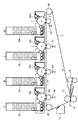
図1に示す画像形成装置としてのカラーレーザープリンタは、転写方式電子写真プロセス利用、接触帯電方式、反転現像方式、最大通紙サイズがA3サイズのカラーレーザープリンタであり、複数個のプロセスカートリッジ10(以下P−CRG)とトナーカートリッジ5をユニットとして有し、一旦第2の画像担持体である中間転写ベルト9に連続的に多重転写し、フルカラープリント画像を得る4連ドラム方式(インライン)プリンタである。本実施形態では、カラーレーザープリンタを例として説明するが、本発明がモノクロレーザープリンタへ適用可能であることは言うまでもない。
A color laser printer as an image forming apparatus shown in FIG. 1 is a color laser printer using a transfer type electrophotographic process, a contact charging method, a reverse development method, and a maximum sheet passing size of A3 size, and includes a plurality of process cartridges 10 ( A quadruple drum (inline) printer having a P-CRG) and
無端状の中間転写ベルト9が、駆動ローラ9e、テンションローラ9f及び2次転写対向ローラ12aに懸架され、図中矢印の方向に回転している。プロセスカートリッジ10は、上記中間転写ベルト9に直列にイエロー(10y)、マゼンタ(10m)、シアン(10c)、ブラック(10bk)の順に4本配置されている。
An endless intermediate transfer belt 9 is suspended from a
トナーカートリッジ5は、プロセスカートリッジ10上に配置されている。トナーカートリッジ5とプロセスカートリッジ10には連結部に開口部が設けられ、その開口部からプロセスカートリッジ10内のトナーが減った場合に必要量がトナー補給される。この補給量は、光学的あるいは電磁気的な手段による現像剤濃度検知部45からの信号を元にCPU(図2におけるCPU30)が決定する。
The
画像形成装置は、潜像担持体としての感光ドラム1、該感光ドラム1を帯電する帯電装置2、感光ドラム1上に潜像を形成する露光装置3、感光ドラム1上の静電潜像をトナーで可視化するための現像装置4、該現像装置4にトナーカートリッジ5、感光ドラム1上の可視化されたトナー像を転写材9上に転写する転写装置9g、転写材9上に転写されたトナー像を定着するための定着装置12、感光ドラム1上に残った転写残トナーを除去するためのクリーニング装置11を備えている。
The image forming apparatus includes a
次に、画像形成のプロセスについて説明する。まず、コンピュータ等の出力装置33から画像情報処理装置32を介して送られてくる画像情報信号は、本画像形成装置のCPU30で受信される。CPU30は、画像形成装置の動作を制御すると共に、露光装置3においてレーザー発光素子を制御して静電潜像形成のためのレーザーの発光させる。感光ドラム1は図1、2において左回りに回転していて、各プロセスカートリッジにおいて順に、感光ドラム1を帯電装置2にて規定電位に帯電した後、画像情報に応じた露光処理を露光装置3が行って感光ドラム1上に静電潜像を形成する。
Next, an image forming process will be described. First, an image information signal sent from the
そして、感光ドラム1上に形成された静電潜像は現像装置4によってトナー像として可視化され、可視化されたトナー像は所定タイミングにて中間転写ベルト9上に多重転写される。中間転写ベルト9上の多重トナー像は、2次転写部で紙などの転写材14に一括転写され、転写材14は定着装置12に搬送され、定着装置12によってトナー像の定着を受けた後に排出される。一方、転写後に感光ドラム1上に残留する転写残トナーは、クリーニング装置8によってクリーニングされる。クリーニング装置8は、クリーニング部材であるクリーニングブレード7を備え、転写残トナーを感光ドラム1から掻き取り、廃トナー容器に収納する。
The electrostatic latent image formed on the
本実施形態においては、感光ドラム1、帯電装置2、現像装置4及びクリーニング装置8をプロセスカートリッジ10としてユニット化し、このプロセスカートリッジ10を画像形成装置200本体に対して着脱可能としている。
In this embodiment, the
プロセスカートリッジ10には、情報記憶媒体400が設けられていて、後述するトナー強制消費に関する情報、プロセス条件に関する情報などが記憶されている。この情報記憶媒体400の例としては、例えば、コネクタ(不図示)や接点(不図示)などを介して接触して通信を行う接触型不揮発性メモリ、コネクタや接点などを介さずにアンテナなどの通信部材を用いて電磁波によって通信を行う非接触型不揮発性メモリ、電源を有する揮発性メモリなど、任意の形態を用いることができる。また、CPU30は、情報記憶媒体400、500と情報通信を行うための情報読み書き手段31を介して情報の読み出し、書き込みを行う。読み出した情報に基づいて後述するトナー強制消費の制御を行う。
The
図15は画像形成装置本体とプロセスカートリッジ10又はトナーカートリッジ5に設けられた不揮発性のメモリとしての情報記憶媒体(400、500)との関係を示すブロック図である。例えば、情報記憶媒体400では情報を記憶する領域が設けられており、情報記憶媒体400の記憶領域に記憶されている情報は画像形成本体に設けられた情報読み書き手段31によって読み出され、本体CPU30に読み込まれる。
FIG. 15 is a block diagram showing the relationship between the main body of the image forming apparatus and information storage media (400, 500) as nonvolatile memories provided in the
次に、現像装置4について図2を参照して詳しく説明すると、感光ドラム1と対向して配置された現像装置4は、現像容器46、現像剤搬送手段としての現像スリーブ41、現像剤の穂高規制部材としてのブレード42を有している。現像装置4の内部は、垂直方向に延在する隔壁によって現像室47(第1室)と撹拌室48(第2室)とに区画され、隔壁の上方部は開放されている。現像室47及び撹拌室48には、非磁性トナーと磁性キャリアを含む2成分現像剤が収容されており、現像室47で余分となった現像剤は撹拌室48側に回収される。
Next, the developing
また、現像室47及び撹拌室48には、それぞれ第1及び第2撹拌スクリュー43,44が配置されている。現像装置4の現像室47は、感光ドラム1に対面した現像域に相当する位置が開口しており、この開口部に一部露出するようにして現像スリーブ41が回転可能に配置されている。現像スリーブ41は非磁性材料で構成され、現像動作時には図示矢印方向に回転し、その内部には磁界発生手段である磁石(マグネットローラ)が固定されている。現像スリーブ41はブレード42によって層厚規制された2成分現像剤の層を担持搬送し、感光ドラム1と対向する現像域で現像剤を感光ドラム1に供給して潜像を現像する。現像効率を向上させるために、現像スリーブ41には電源から、例えば直流電圧に交流電圧が重畳された現像バイアス電圧が印加される。
The developing
このような現像装置4のマグネットローラは、5極構成からなり、現像室撹拌スクリューで撹拌された現像された現像剤は、汲み上げのための搬送用磁極(汲み上げ極)N2の磁力で拘束され、現像スリーブ41の回転により現像剤溜り部5へ搬送される。現像剤量は、安定した現像剤を拘束するために、ある一定以上の磁束密度を有する搬送用磁極(カット極)S2で十分に拘束し、そして磁気ブラシを形成しつつ搬送される。次いで、ブレード42、即ち、穂高規制部材で磁気ブラシを穂切りして現像剤量を適正にし、搬送用磁極N1で搬送される。
The magnetic roller of such a developing
現像剤はポリエステル樹脂に顔料を分散した非磁性トナーと、フェライトをシリコーン樹脂でコーティングした磁性キャリアから成り、現像室と撹拌室での撹拌と、摺擦によってトナーにマイナスの電荷が付与される。現像によって消費された分のトナーはトナーカートリッジから供給されるが、補給されたばかりのトナーも前記のような撹拌と摺擦によって適正な電荷が付与さる。 The developer comprises a non-magnetic toner in which a pigment is dispersed in a polyester resin and a magnetic carrier in which ferrite is coated with a silicone resin, and a negative charge is imparted to the toner by stirring and rubbing in the developing chamber and the stirring chamber. The amount of toner consumed by development is supplied from the toner cartridge, but the just-replenished toner is also given an appropriate charge by stirring and rubbing as described above.
即ち、現像剤中のトナーは、補給され、撹拌・摺擦によって電荷を付与され、現像されるという過程の中で順次入れ替わるが、この入れ替わりが少ないと、トナーは過剰に帯電してしまう。また、長時間の攪拌、摺擦によりトナーの劣化も進行する。このように過剰な帯電または劣化したトナーは現像時に濃度が薄くなったり、転写不良で均一転写ができないなどの画像劣化を引き起こす。 That is, the toner in the developer is replenished in the process of being replenished, charged by stirring and rubbing, and developed, but if this change is small, the toner will be overcharged. In addition, the toner deteriorates due to long-time stirring and rubbing. Such excessively charged or deteriorated toner causes image deterioration such as a decrease in density at the time of development or a uniform transfer due to poor transfer.
そこで、本実施形態では、トナーを強制的に消費させることにより、トナーを強制的に入れ替え、トナーの過剰な帯電を防止し、画質の低化を防いでいる。なお、このトナーを強制的に消費させる制御は、記録紙に画像を記録させる通常の画像形成を行うタイミングではない、後回転、前回転、紙間などの非画像形成時に実行される制御である。 Therefore, in the present embodiment, by forcibly consuming the toner, the toner is forcibly replaced, the toner is prevented from being excessively charged, and the image quality is prevented from being lowered. The control for forcibly consuming the toner is a control that is executed at the time of non-image formation such as post-rotation, pre-rotation, and paper interval, not the timing of normal image formation for recording an image on recording paper. .
トナーの強制消費処理は以下の様に行われる。画像形成時と同様に感光ドラム1上を帯電装置2で帯電し、露光装置3で感光ドラム1の長手全域を所定の時間露光する。その露光部に対して現像装置4で画像形成時と同様にトナーを現像することで現像容器46からのトナーの強制消費を行なわせる。
The forced toner consumption process is performed as follows. Similarly to the image formation, the
このとき転写装置9gには電圧を印加していないため、感光ドラム1上に強制消費されたトナーは、ほぼ転写されることなく転写位置を通過し、クリーニング装置8にて除去される。また、転写ベルト9に転移するトナーも多少は存在するがそのようなトナーは転写ベルトのクリーナ11に回収される。
At this time, since no voltage is applied to the
本実施形態では、露光は感光ドラム1の長手全域において、レーザー照射量はFFHで高濃度現像することで、トナー消費量を多くし短時間で強制消費動作を終わらせることが可能としている。ただし、レーザーの照射量は必ずしもFFHである必要はなく、時間に余裕がある場合は、ある程度効率良くトナーを現像させるような量であれば良い。
In the present embodiment, the exposure is performed at a high density with a laser irradiation amount of FFH throughout the entire length of the
このように劣化したトナーを消費することで、新たにフレッシュなトナーが消費された量だけトナー補給槽たるトナーカートリッジ5から現像装置4内に補給される。従って、現像容器46内のトナーの入れ替えが行われ、トナーの流動性及び帯電量が適切なものとなる。
By consuming the deteriorated toner as described above, the fresh toner is replenished into the developing
次に、トナー強制消費処理の態様に応じた、画像レベルと印刷枚数の関係について、図8から図10を参照して説明する。 Next, the relationship between the image level and the number of printed sheets according to the mode of forced toner consumption processing will be described with reference to FIGS.
まず、図8は、0.5%の印字率で、トナー強制消費処理を行わずに所定枚数の印刷を継続して行った場合の印刷枚数と画像レベルの関係を示すグラフである。図8のグラフでは、横軸がプリント枚数、縦軸が画像レベルを表しており、画像レベルは下に行くほど低下していることを示している。この検証では、3種類のキャリア1から3までを利用して、印刷枚数に対する画像レベルの変化を観察した。
First, FIG. 8 is a graph showing the relationship between the number of printed sheets and the image level when a predetermined number of sheets are continuously printed without performing the forced toner consumption process at a printing rate of 0.5%. In the graph of FIG. 8, the horizontal axis represents the number of prints and the vertical axis represents the image level. The image level decreases as it goes down. In this verification, changes in the image level with respect to the number of printed sheets were observed using three types of
図8では、キャリア1は800枚まで許容範囲を維持できるが、キャリア3はその半分の400枚程度までしか許容範囲を維持できていない。これは、キャリア特性のばらつきによって、トナーを帯電させやすいもの、逆に帯電させにくいものがあり、そのため印字率と画質低下の関係に違いが現われたものと考えられる。また、上記許容範囲とは印刷物として許容される画像レベルの範囲を意味する。
In FIG. 8, the allowable range of the
そこで、トナー強制消費を同一タイミングで同じ量だけ実行すると、その結果は図9に示す通りになる。ここで、印字率の閾値は2.0%、タイミングは250枚ごとであり、画質低下を引き起こしにくいキャリア(キャリア1)に合わせたものである。図9では、トナー強制消費処理の実行により一旦は画像レベルが回復するものの、その後、印刷−トナー強制消費処理を繰り返して実行すると画像レベルは許容範囲から外れてしまうキャリアが存在する(キャリア2、3)。
Therefore, when the forced toner consumption is executed by the same amount at the same timing, the result is as shown in FIG. Here, the threshold of the printing rate is 2.0%, the timing is every 250 sheets, and it is adjusted to the carrier (carrier 1) that hardly causes the image quality deterioration. In FIG. 9, although the image level is temporarily recovered by executing the forced toner consumption process, there is a carrier whose image level falls outside the allowable range when the print-toner forced consumption process is repeatedly executed thereafter (
これに対して、画質の低下を引き起こしやすいキャリア(キャリア3)に印字率の閾値を合わせると、印字率の閾値は3.0%となる。この場合、画質低下を引き起こしにくいキャリア(キャリア1)については、トナー強制消費処理の頻度が増加するために、必要以上にトナーが消費されてしまう。従って、画質の低下を避けつつも消費量を不必要に増大させないためには、キャリア毎の特性のバラツキに対応して、各キャリア毎に印字率の閾値を変える必要がある。 On the other hand, when the threshold of the printing rate is matched with the carrier (carrier 3) that tends to cause the image quality to deteriorate, the threshold of the printing rate becomes 3.0%. In this case, for the carrier (carrier 1) that is less likely to cause image quality degradation, the frequency of toner forced consumption processing increases, so that toner is consumed more than necessary. Therefore, in order not to unnecessarily increase the consumption while avoiding the deterioration of the image quality, it is necessary to change the threshold value of the printing rate for each carrier in accordance with the variation in characteristics for each carrier.
このように各キャリア毎(つまりプロセスカートリッジ毎)に閾置を適用するためには、本体側に閾置を持たせておくのでは対応が困難であり、各キャリアに適切な印字率の閾値をプロセスカートリッジの情報記憶媒体に格納し、トナー強制消費モードを実施する際にはその情報を用いて行なうことが好ましい。 Thus, in order to apply a threshold value for each carrier (that is, for each process cartridge), it is difficult to provide a threshold value on the main body side, and an appropriate printing rate threshold value is set for each carrier. It is preferable to store the information in the information storage medium of the process cartridge and use the information when executing the forced toner consumption mode.
キャリアごとにカートリッジの情報記憶媒体に印字率の閾値を格納して、その値をもとに強制トナー消費を行なった場合の画像レベルの推移を図10に示す。ここにおいて、印字率の閾値はそれぞれキャリア1は2.0%、キャリア2は2.5%、キャリア3は3.0%であり、250枚ごとにトナー強制消費処理を行なっている。どのキャリアについても、画像レベルが許容範囲を超えることなく良好な範囲を推移している。
FIG. 10 shows the transition of the image level when the threshold value of the printing rate is stored in the information storage medium of the cartridge for each carrier and the forced toner consumption is performed based on the threshold value. Here, the threshold values of the printing rate are 2.0% for
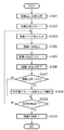
次に、図4を参照して上記図10の結果に対応する本実施形態におけるトナー強制消費処理について説明する。まず、ステップS401においてプリント信号が入力されると、ステップS402において、各ステーションのプロセスカートリッジ10の情報記憶媒体400に記憶されている該カートリッジ10に適した最低印字率の値(印字率の閾値)が本体側に読み込まれる。
Next, the toner forced consumption process in the present embodiment corresponding to the result of FIG. 10 will be described with reference to FIG. First, when a print signal is input in step S401, a minimum print rate value (print rate threshold value) suitable for the
ステップS403において実際に画像形成がスタートすると、ステップS404において画像データが読み込まれビデオカウントが算出される。ビデオカウントはすでに今までのプリントで本体ROM34に積算されている値に積算される。また、プリント枚数も同様に本体ROM34に格納されている積算枚数に加えられ、その積算枚数がNp枚であるかを判断する。Np枚に到達していなければ(ステップS406で「NO」)、Np枚に到達するまで同様のシーケンスでプリント動作を行なう。
When image formation actually starts in step S403, image data is read and a video count is calculated in step S404. The video count is integrated with the value already accumulated in the
上記プリント枚数Npは、例えば、100枚や250枚が相当するが、これに限らずプロセスカートリッジのキャリアの特性に応じて設定してもよい。 The number Np of prints corresponds to, for example, 100 sheets or 250 sheets, but is not limited to this, and may be set according to the characteristics of the carrier of the process cartridge.
プリント枚数がNp枚になった時点で(S406において「YES」)、ステップS407においてビデオカウントデータとプリント枚数から計算を行い各カートリッジの平均の印字率(プリント1枚あたりの印字率)を算出する。その値がカートリッジから読み込んだ印字率の閾値を超えていないカートリッジがあれば(ステップS407において「YES」)、ステップS408において、そのカートリッジについて平均印字率が印字率の閾値になるように差分をトナー消費する。一方、平均印字率が所定の値を超えているカートリッジについては(ステップS407において「NO」)、トナー強制消費動作は行なわれずそのまま画像形成が継続される。 When the number of prints reaches Np (“YES” in S406), calculation is performed from the video count data and the number of prints in step S407, and the average print rate (print rate per print) of each cartridge is calculated. . If there is a cartridge whose value does not exceed the threshold of the printing rate read from the cartridge (“YES” in step S407), in step S408, the difference is set to the toner so that the average printing rate becomes the printing rate threshold for that cartridge. Consume. On the other hand, for the cartridge whose average printing rate exceeds the predetermined value (“NO” in step S407), the toner forced consumption operation is not performed and the image formation is continued as it is.
ただし、トナー強制消費動作を行なったカートリッジもそうでないカートリッジも、ステップS409において、本体ROM34のプリント枚数はNp枚でリセットされ、このとき累積ビデオカウント値もリセットされる。その後再び、Np枚まで積算し計算によりトナー強制消費動作を行なうかの判断をする。このシーケンスを繰り返すことで、キャリアの特性に応じて常に適正量のトナーが入れ替えられることになり、同じトナーを過度に摺擦することを防止することができる。その結果、トナーの過剰帯電や劣化が抑制され、画像品質の低下を防止できる。
However, in step S409, the number of prints in the
以上のように、本実施形態に対応する本発明では、プロセスカートリッジに情報記憶媒体が設けられていて、その情報記憶媒体にそのキャリアに適切な印字率閾値を記憶させ、その値を用いてトナー強制消費シーケンスを実行することで、常にそのプロセスカートリッジにあった印字率を保ち、トナーはキャリアから過剰に帯電されることなく、また劣化することなく、安定した画像形成を行なうことが可能となる。 As described above, in the present invention corresponding to the present embodiment, an information storage medium is provided in the process cartridge, and an appropriate printing rate threshold value is stored in the carrier in the information storage medium, and the toner is obtained using the value. By executing the forced consumption sequence, it is possible to always maintain the printing rate suitable for the process cartridge and to perform stable image formation without excessively charging or deteriorating the toner from the carrier. .
[第2の実施形態]
第1の実施形態では、プロセスカートリッジの情報記憶媒体400に印字率の閾値をトナー強制消費に関する情報として記憶していたが、本実施形態では、印刷枚数を記憶することを特徴とする。また本実施形態では、印字率の閾値を画像形成装置本体のROM34に記憶しておいてもよい。なお、画像形成装置本体は第1の実施形態の構成と同じである。
[Second Embodiment]
In the first embodiment, the threshold value of the printing rate is stored as information on the forced toner consumption in the
これにより本実施形態に対応する画像形成装置では、図6のキャリア1のように長期にわたって品質が保てるキャリアに関しては、閾値を変更せずにトナー強制消費動作を実施するタイミングを遅らせることができ、キャリア3のように画質の低下を引き起こしやすいキャリアに関しては、早いタイミングでトナー強制消費動作を行なうことができる。
As a result, the image forming apparatus corresponding to the present embodiment can delay the timing of performing the forced toner consumption operation without changing the threshold for a carrier that can maintain quality over a long period of time, such as the
トナー強制消費動作を行なうタイミングはキャリアごとに適切な値に設定することができ、例えば、キャリア1は250枚、キャリア2は170枚、キャリア3は125枚としてプロセスカートリッジ10の情報記憶媒体400に格納することができる。また、印字率の閾値は、例えば2.0%として固定でよく、その値は本体ROM34に格納されるのが好ましい。これにより、図11に示すように、画像レベルは高い画像レベルでの許容範囲内で推移する。
The timing for performing the forced toner consumption operation can be set to an appropriate value for each carrier. For example, the
このように、本実施形態では、キャリアごとに必要最低限の時間間隔でトナー強制消費処理を実行することで、必要以上にトナー強制消費動作が入ることで印刷スピードが落ちるといった問題を解消し、プリントスピードの遅延を必要以上に起こすことなく、画像品質を安定して保つことが可能となる。 As described above, in the present embodiment, by executing the forced toner consumption process at a necessary minimum time interval for each carrier, the problem that the printing speed is reduced due to the forced toner consumption operation more than necessary is solved, It is possible to keep the image quality stable without causing a print speed delay more than necessary.
[第3の実施形態]
上記第1及び第2の実施形態では、トナー強制消費に関する情報をプロセスカートリッジ10の情報記憶媒体400に記憶していたが、本実施形態では、トナーカートリッジ5の情報記憶媒体500に格納することを特徴としている。以下においては格納される情報を印字率の閾値として説明するが、印刷枚数を格納しても良いのは言うまでもない。また、本実施形態における画像形成装置の構成は、第1の実施形態の画像形成装置と同じ構成である。
[Third Embodiment]
In the first and second embodiments, information related to forced toner consumption is stored in the
さらに、情報記憶媒体500の構成は、第1の実施形態で説明した情報記憶媒体と同様であり情報記憶媒体500の所定の記憶領域にトナー強制消費に関する情報を記憶している。
Further, the configuration of the
以下、本実施形態に対応する本願発明の構成について以下にさらに詳しく説明する。図12に示すようにトナー1、トナー2、トナー3と3種類のトナーは画質の低下度合いに差があり、このようなトナーに対して同じ印字率の閾値(ここでは2.0%)、同じタイミング(200枚毎)で、トナー強制消費シーケンスを実行すると、トナーの消費が足りずに画像レベルの低下を招くという問題が生ずる。また、レベルの良いトナーに関しては必要以上にトナーを消費している可能性がある。
Hereinafter, the configuration of the present invention corresponding to the present embodiment will be described in more detail below. As shown in FIG. 12, the
そのため、本実施形態ではトナー毎に適切な印字率の閾値を設ける。ここでは、印字率の閾値をトナー1は1.5%、トナー2は2.0%、トナー3は2.5%として、トナーカートリッジに設けられた情報記憶媒体500に格納する。そうすることで、図13に示すように無駄にトナーを消費することなく画像レベルの低下を防ぐことが可能となる。
Therefore, in this embodiment, an appropriate printing rate threshold is provided for each toner. Here, the threshold values of the printing rate are 1.5% for
なお、本実施形態におけるトナー強制消費処理の流れは、第1の実施形態(図4)と同様であるため説明は省略する。 Note that the flow of the forced toner consumption process in the present embodiment is the same as that in the first embodiment (FIG. 4), and a description thereof will be omitted.
ここでは印字率の閾値をトナーカートリッジの情報記憶媒体500に格納したが、図14に示すようにトナーごとに適切なトナー強制消費動作タイミング(印刷枚数)を格納することでも、同様の効果が得られる。それぞれのトナーが収納されているトナーカートリッジ5の情報記憶媒体500に格納された印刷枚数は、例えばトナー1が200枚、トナー2は120枚、トナー3は100枚と設定することができる。
Here, the threshold of the printing rate is stored in the
このように、トナーに応じて適切な強制消費の量に関する情報または強制消費を実行するタイミングをトナーカートリッジ5の情報記憶媒体500に格納することで、キャリアよりもトナーの方がトナー劣化または過帯電による画像劣化に影響する場合にも対応が可能となる。
Thus, by storing information on the amount of forced consumption appropriate for the toner or the timing for executing forced consumption in the
以上のように、トナーの製造条件のばらつきによる特性の違いに応じて、適宜トナーカートリッジの情報記憶媒体に格納する情報を変更することで、画像形成装置本体側に固定の情報を格納していたときのようにトナーを無駄に消費することなく、またユーザーに余計なストレスを与えることなく良質な画像形成を行なうことが可能となる。 As described above, fixed information is stored on the main body of the image forming apparatus by appropriately changing information stored in the information storage medium of the toner cartridge in accordance with a difference in characteristics due to variations in toner manufacturing conditions. As a result, it is possible to perform high-quality image formation without wastefully consuming the toner and without adding extra stress to the user.
上記本実施形態では、平均印字率を算出するためのビデオカウントデータとプリント枚数を本体ROM34に格納している場合を説明したが、これらの情報についてもカートリッジの情報記憶媒体に格納しておくことで、カートリッジが違う本体で使用された際にも問題を生じることなくさらに安定した画像形成を行うことが可能となる。
In the above embodiment, the video count data for calculating the average printing rate and the number of prints are stored in the
例えば、本体ROM34に格納している場合には、使用していたカートリッジが交換され違うカートリッジが使用されると、交換以前に使用していたカートリッジの累積印字率とプリント枚数から処理が開始され、無駄にトナーを消費してしまう可能性がある。
For example, in the case where the cartridge is stored in the
また、カートリッジ交換で本体ROM34に格納された情報をリセットしてゼロからスタートしたとしても、新たに使用されるカートリッジの以前の使用状況がわからないため、画質の劣化を招く可能性がある。
Further, even if the information stored in the
従って、累積印字率、プリント枚数もカートリッジの情報記憶媒体に格納しておくことが望ましい。 Accordingly, it is desirable to store the cumulative printing rate and the number of prints in the information storage medium of the cartridge.
また、以上に説明した第1乃至第3の実施形態では、トナー強制消費動作を行なうか否かの基準を印刷枚数としていた(図4のステップS406)が、これに限らずスリーブの回転数、スクリューの回転数、又はドラムの回転数など、印刷枚数と関連する値を代わりの基準としても良い。 In the first to third embodiments described above, the criterion for determining whether or not to perform the forced toner consumption operation is the number of printed sheets (step S406 in FIG. 4). A value related to the number of printed sheets, such as the number of rotations of the screw or the number of rotations of the drum, may be used as an alternative reference.
また、本各実施形態では、トナー強制消費に関する情報をトナーカートリッジ5の情報記憶媒体に格納する方法と、プロセスカートリッジ10の情報記憶媒体に格納する方法とを別の実施形態として記載したが、両者を併用することも可能である。この場合は、画像劣化が起きないように印字率や動作の間隔はトナー劣化、トナーの過帯電に有利な方を選ぶようにするのが望ましい。また、両方の情報から適正な量とタイミングを算出することも可能である。
In each of the embodiments, the method for storing the information related to the forced toner consumption in the information storage medium of the
上記各実施形態中は、所定の枚数でトナー強制消費動作を実行するか判断しているが、所定の枚数以内であれば画像形成後にトナー強制消費処理を実行することで、実際のプリント処理への影響を無くして、プリントスピードを遅らせることなくトナーの劣化や過剰帯電を防止することが可能となる。 In each of the above-described embodiments, it is determined whether the forced toner consumption operation is executed with a predetermined number of sheets. However, if it is within the predetermined number of sheets, the forced toner consumption process is executed after image formation, and the actual print processing is performed. Thus, it is possible to prevent toner deterioration and overcharging without delaying the printing speed.
以上のように、上記実施形態に対応する本発明によれば、現像カートリッジなどの着脱可能なユニットに記憶手段を設け、そこにトナー強制消費動作に関する情報をもたせることで、現像剤の製造ばらつきなどによる特性の違いに応じて適切な現像剤の強制消費動作に関する情報を入れることが可能となる。 As described above, according to the present invention corresponding to the above-described embodiment, a storage unit is provided in a detachable unit such as a developing cartridge, and information related to the forced toner consumption operation is provided therein, thereby producing variations in developer manufacturing. It is possible to enter information regarding the forced developer consumption operation appropriate to the difference in characteristics.
また、現像剤のみならず、現像手段に用いられる部材の特性の違いに応じて適宜適切なトナー強制消費動作の情報をカートリッジの記憶手段に格納することも可能となる。そのため、必要以上にトナーを消費したり、消費が足りないことで画像の劣化が起こることなく安定して長期にわたって画像形成が可能となる。 In addition, it is possible to appropriately store information on the forced toner consumption operation in the cartridge storage unit according to the difference in the characteristics of not only the developer but also the member used for the developing unit. For this reason, it is possible to stably form an image over a long period of time without causing unnecessary deterioration of the image due to excessive consumption or consumption of toner.
なお、本実施形態は、現像剤としてトナーとキャリアとからなるニ成分現像剤を用いた系、及び、トナーからなる一成分現像剤を用いら系に適用可能である。 The present embodiment can be applied to a system using a two-component developer composed of a toner and a carrier as a developer, and a system using a one-component developer composed of a toner.
[第4の実施形態]
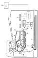
図7は本発明に係る画像形成装置の一実施形態の概略断面を示す。本実施形態の画像形成装置Aは、画像情報に応じて電子写真方式にて記録媒体14、例えば記録用紙、OHPシートなどに画像を形成するレーザービームプリンタとされる。又、本実施形態の画像形成装置Aは、詳しくは後述するように、プロセスカートリッジBが着脱可能とされている。
[Fourth Embodiment]
FIG. 7 shows a schematic cross section of an embodiment of an image forming apparatus according to the present invention. The image forming apparatus A according to the present embodiment is a laser beam printer that forms an image on a
画像形成装置Aは、パーソナルコンピュータなどのホスト33に接続されて用いられる。コントローラ部32において、ホスト33からのプリント要求信号並びに画像データを処理し、露光装置3を制御することで、像担持体1上に静電潜像を形成する。
The image forming apparatus A is used by being connected to a
感光ドラム1は、感光ドラム1に加圧当接されたローラ状の帯電部材、即ち、DC接触帯電ローラ(帯電ローラ)2によって一様に帯電される。帯電ローラ2には電源20から帯電バイアスとして所定の値に固定された直流電圧が印加され、感光ドラム1の表面を負に一様に帯電させる。帯電ローラ2は感光体ドラム1の回転により、図中矢印R4方向に従動回転する。帯電ローラ2は、感光ドラム1の長手方向(記録媒体14の搬送方向に直交する方向)略全域に亙って当接されている。
The
一様に帯電された感光ドラム1は、露光装置3からのレーザー光Lにより露光され、その表面に静電潜像が形成される。露光装置3は、レーザー光源、ポリゴンミラー、レンズ系などを有し、コントローラ部の制御により、感光ドラム1上を走査露光することができる。
The uniformly charged
その後、この静電潜像は、現像装置4によって現像剤が供給されて、トナー像として可視化される。つまり、現像装置4は、一成分現像剤として負帯電性の非磁性トナー(トナー)22を収容する現像容器46を有する。本実施形態では、トナー22には、小粒径化及び低融点化を達成し、且つ、転写効率を向上させるために、重量平均粒径約7μmの略球形トナーを用いた。
Thereafter, the electrostatic latent image is visualized as a toner image by supplying a developer by the developing
そして、感光ドラム1と対向する現像容器46の一部は、感光ドラム1の長手方向略全域に亙り開口しており、この開口部にローラ状の現像剤担持体(現像手段)である現像ローラ41が配置されている。現像ローラ41は、現像装置4の図中左上方に位置する感光ドラム1に所定の侵入量となるように押圧、接触され、回転駆動される。又、その表面は、トナー22との摺擦確率を高め、且つ、トナー22の搬送を良好に行うために、適度な凹凸を有している。
A part of the developing
現像ローラ41の図中右下方には、現像ローラ41への現像剤を供給し、又未現像トナーを現像ローラ41から剥ぎ取る手段として、弾性ローラ24が当接されている。弾性ローラ24は、回転可能に現像容器46に支持されている。又、弾性ローラ24は、現像ローラ41へのトナー供給及び未現像トナーの剥ぎ取り性の点からゴムスポンジローラとし、現像ローラ41と同一方向に回転駆動する。
An
又、現像装置4は、現像ローラ41に担持させるトナー量を規制する現像剤層厚規制部材として、現像ブレード42を備えている。現像ブレード42は、弾性を有するリン青銅製の金属薄板で構成され、自由端側の先端近傍を現像ローラ41の外周面に面接触にて当接するように設けられている。弾性ローラ24との摺擦により現像ローラ41上に担持されたトナーは、現像ブレード42との当接部を通過する際に摩擦帯電により電荷付与され、且つ、薄層に規制される。
Further, the developing
このような構成の現像装置4において、現像ローラ41には、現像バイアスとして所定の値に固定された直流電圧が印加される。これによって、本実施形態では、一様に帯電された感光ドラム1の表面の、負電荷が減衰した露光部を反転現像により現像する。
In the developing
一方、記録媒体14は記録媒体収容部から供給ローラなどにより分離給送され、レジストローラで一旦停止する。レジストローラは、記録媒体の記録位置と感光ドラム1へのトナー像の形成タイミングとの同期をとり、転写手段である転写ローラ9gと感光ドラム1との対向部(転写部)へと、記録媒体14を送り出す。
On the other hand, the
こうして、可視化された感光ドラム1上のトナー像は、転写ローラ9gの作用によって記録媒体14に転写される。トナー像を転写された記録媒体14は、定着装置12に搬送される。ここで、記録媒体14上の未定着のトナー像は、熱、圧力よって記録媒体14に永久定着される。その後、記録媒体14は排出ローラなどにより機外に排紙される。
Thus, the visualized toner image on the
又、転写されずに感光ドラム1上に残留した転写残トナーは、クリーニング手段(クリーナ)8によって清掃する。クリーナ8は、クリーニング部材であるクリーニングブレード7により転写残トナーを感光ドラム1から掻き取り、廃トナー容器に収納する。クリーニングされた感光ドラム1は画像形成に供される。
Further, untransferred toner remaining on the
本実施形態では、画像形成装置Aは、電子写真感光体を備えた像担持体と、この像担持体に作用するプロセス手段とを一体的にカートリッジ化し、このカートリッジを装置本体に対して着脱可能とするプロセスカートリッジ方式を採用している。このプロセスカートリッジは、感光ドラム1、帯電ローラ2、現像装置4、クリーナ8が一体的にカートリッジ化されることで、プロセスカートリッジBとして形成され、画像形成装置A本体に着脱可能とされている。また、プロセスカートリッジBは、画像形成装置Aが備える装着手段を介して、取り外し可能に装置本体に装着される。
In this embodiment, in the image forming apparatus A, an image carrier provided with an electrophotographic photosensitive member and a process unit acting on the image carrier are integrally formed into a cartridge, and the cartridge can be attached to and detached from the apparatus main body. The process cartridge method is adopted. This process cartridge is formed as a process cartridge B by integrally forming the
本実施形態によれば、プロセスカートリッジBには情報記憶媒体400が設けられている。情報記憶媒体400の例としては、例えば、コネクタ(不図示)や接点(不図示)などを介して接触して通信を行う接触型不揮発性メモリ、非接型触不揮発性メモリ、電源を有する揮発性メモリなど、任意の形態を用いることができる。本実施形態では、情報記憶媒体として非接型触不揮発性メモリがプロセスカートリッジBに搭載されている。
According to the present embodiment, the process cartridge B is provided with the
非接型触不揮発性メモリは、メモリ側の情報伝達手段であるアンテナ(図示せず)を有し、アンテナを用いた無線通信で画像形成装置本体が備えた制御手段(CPU)30と通信することで、情報の読み出し及び書き込みが可能である。本実施形態では、CPU30は装置本体側の情報通信部として情報読み書き手段31が設けられており、メモリ400の情報の読み書き手段の機能を備えている。
The non-contact type non-volatile memory has an antenna (not shown) as information transmission means on the memory side, and communicates with a control means (CPU) 30 provided in the image forming apparatus main body by wireless communication using the antenna. Thus, information can be read and written. In the present embodiment, the
なお、メモリ26は第1の実施形態で説明した情報記憶媒体と同様であり、メモリ26(記憶媒体)の所定の記憶領域にトナー強制消費に関する情報を記憶している。 The memory 26 is the same as the information storage medium described in the first embodiment, and stores information related to forced toner consumption in a predetermined storage area of the memory 26 (storage medium).
このような構成の現像手段を用いたプロセスカートリッジBで低印字画像を大量に印刷すると現像ローラ41、弾性ローラ24付近のトナーがなかなか入れ替わらないためトナーの劣化が進み、転写ムラ、濃度低下などの画像劣化を招く。トナー劣化は、主に現像ローラ41と現像ブレード42との摺擦により起こる。よって、トナー強制消費動作により摺擦を受け劣化したトナーを強制的に消費し、まだ摺擦を受けていないフレッシュなトナーに入れ替わらせて、画質の低下を防止する。
When a large amount of low-printed images are printed with the process cartridge B using the developing means having such a configuration, the toner in the vicinity of the developing
本実施形態ではトナー強制消費動作を以下のように実施した。A4サイズの画像形成に必要な現像ローラ41の回転数をTとし、例えば、通紙枚数100枚に相当する現像ローラ41の回転数100T毎に、1次帯電バイアスを−650Vとすることにより感光ドラム1の表面電位が露光電位となるよう設定し、非画像形成時(後回転、前回転、紙間など)にベタ黒画像1ページに相当する劣化トナーを感光ドラム1上に現像することにより、劣化したトナーを強制的に消費し、画像形成枚数増加に伴う画質の低下を低減した。
In this embodiment, the forced toner consumption operation is performed as follows. The number of rotations of the developing
しかし、トナー劣化のレベルについては使用されているトナーの特性によってばらつきが生じる。現像ローラ回転数100Tは標準的なトナーBに対して設定されたものであり、トナー劣化に強いトナーAであれば、ローラ回転数が100T毎では当然画質に問題はなく、150Tまで画像上問題が生じなかった。しかし、トナー劣化に弱いトナーCの場合、ベタ黒画像1ページ相当のトナーを100Tごとに消費するのでは不十分で、100T毎に通常の1.5倍のトナー強制消費量が必要であった。または、70T毎に通常量のトナー消費を行なう必要があった。 However, the level of toner deterioration varies depending on the characteristics of the toner used. The developing roller rotation speed 100T is set for the standard toner B. If the toner A is resistant to toner deterioration, there is no problem in the image quality when the roller rotation speed is every 100T, and there is an image problem up to 150T. Did not occur. However, in the case of the toner C that is weak against toner deterioration, it is not sufficient to consume the toner corresponding to one page of a solid black image every 100 T, and the toner forced consumption amount 1.5 times the normal amount is required every 100 T. . Alternatively, it is necessary to consume a normal amount of toner every 70T.
このようにトナー劣化レベルがトナーロットなどによって違うため、画像形成装置AのROM34に、予め決められた消費量と現像ローラ回転数の閾値が格納されている場合には、無駄にトナーを消費したり、必要以上にトナー強制消費動作が入ることで印刷スピードが落ちるなどの問題が発生する。また、逆にそれらを満たすために、消費量を少なくしたりや実行間隔を長くすると、劣化しやすいトナーやキーパーツの組み合わせで、トナー消費量が足りずに画像劣化が起こることがある。
As described above, since the toner deterioration level varies depending on the toner lot or the like, if the
そこで、本実施形態ではトナー毎にカートリッジの情報記憶媒体にトナー強制消費動作を行なう現像ローラ回転数を格納する。トナーAは150T、トナーBは100T、トナーCは70Tとした。それぞれのプロセスカートリッジに適したトナー強制消費を実行するタイミングに関する情報(トナー強制消費を行なう現像ローラ回転数)を格納しておくことで、安定して良質な画像の提供を行なうことができるようになる。これは、上記のようなトナー毎のトナー劣化レベルのばらつきにその都度対応することが可能となるためである。 Therefore, in this embodiment, the number of rotations of the developing roller for performing the toner forced consumption operation is stored in the information storage medium of the cartridge for each toner. The toner A was 150T, the toner B was 100T, and the toner C was 70T. By storing information on the timing for executing forced toner consumption suitable for each process cartridge (developing roller rotation speed for forced toner consumption), it is possible to provide a stable and high-quality image. Become. This is because it is possible to cope with the variation in the toner deterioration level for each toner as described above.
このようにプロセスカートリッジBの情報記憶媒体400に、トナー強制消費に関する情報を格納し利用することで、上記のようなトナーのばらつきだけでなく現像ローラ41、規制ブレード42などの部材のばらつきにも対応が可能となる。
In this way, by storing and using information on forced toner consumption in the
本実施形態ではトナー強制消費動作を連続プリントジョブ中に行っているが、現像ローラ回転数の閾値内であれば、動作を連続プリント終了後に行うことにより、連続プリントのスピードを落とさずに本実施形態と同様の効果を得ることが可能である。 In this embodiment, the forced toner consumption operation is performed during a continuous print job. However, if the developing roller rotation speed is within the threshold value, the operation is performed after the end of continuous printing, so that the continuous printing speed is not reduced. It is possible to obtain the same effect as the form.
また、本実施形態では、画像形成時以外(非画像形成時)の感光ドラム1上への現像時に1次帯電バイアスにより感光ドラム1の表面電位を露光電位とすることにより、1次帯電の放電による感光ドラム1表面の劣化が無く現像が可能となるが、本発明は、この態様に限定されるものではなく、本発明の原理は、感光ドラム1を露光することにより画像形成時以外に現像を行う場合にも適用でき、本実施形態と同様の効果を得ることができる。
In the present embodiment, the discharge of primary charging is performed by setting the surface potential of the
本実施形態では接触現像を採用しているが、本発明は接触現像に限るものではなく、トナーが現像プロセスにおいて摺擦されるような画像形成装置、例えばトナー供給ローラ、弾性規制ブレード等を用いた非接触ジャンピング現像法等において有効である。 In this embodiment, contact development is adopted. However, the present invention is not limited to contact development, and an image forming apparatus in which toner is rubbed in the development process, for example, a toner supply roller, an elastic regulation blade, or the like is used. This is effective in the non-contact jumping development method.
[第5の実施形態]
第1の実施形態から第4の実施形態までは、所定枚数で印字率の閾値を下回ったときにトナー強制消費動作を実行していたが、本実施形態では、現像装置の使用量としての印刷枚数に対して画質良好であるための最低の消費トナー量と実際に消費しているトナー量との差分を確認し、その差分が所定値△Xに達したときにトナー強制消費を実施することを特徴としている。消費トナー量は、直接トナーの量を確認しているわけではなく、印字率の情報などから計算している。
[Fifth Embodiment]
From the first embodiment to the fourth embodiment, the forced toner consumption operation is performed when the predetermined number of sheets falls below the threshold of the printing rate. In this embodiment, printing is performed as the usage amount of the developing device. Check the difference between the minimum amount of toner consumed for good image quality and the amount of toner actually consumed, and perform forced toner consumption when the difference reaches a predetermined value ΔX It is characterized by. The amount of consumed toner is not directly confirmed by the amount of toner, but is calculated from information on the printing rate.
本実施形態の画像形成装置の構成は第1の実施形態で説明した図1、図2と同様であり、また、画像形成装置本体とプロセスカートリッジに設けられた不揮発性のメモリとしての情報記憶媒体との関係を示すブロック図15の構成も同様であるため説明は省略する。 The configuration of the image forming apparatus of the present embodiment is the same as that of FIGS. 1 and 2 described in the first embodiment, and an information storage medium as a nonvolatile memory provided in the image forming apparatus main body and the process cartridge. Since the configuration of the block diagram 15 showing the relationship is also the same, description thereof will be omitted.
ここでは、印刷枚数に対して画質良好であるための最低の消費トナー量は、画像良好であるための最低の印字率(印字率の閾値)に印刷枚数を掛け合わせた値としている。なお、画像形成装置本体は、第1の実施形態の構成と同じである。また、本実施形態では所定値△Xと印字率の閾値がプロセスカートリッジの情報記憶媒体に記憶されている。(トナー強制消費動作を制御するための情報として所定値△X、印字率の閾値が記憶されている。)
本実施形態の方法によってトナー強制消費動作を行なうことで、どのような印字率であっても印字率の閾値以下であれば必ず所定枚数毎にトナー強制消費動作を行うで不足分を消費するのではなく、印字率に応じて良好な画像を保つぎりぎりまで待ってからトナー強制消費動作を入れることが可能となる。つまり低印字率画像がしばらく続いたとしても、画像劣化が現われるギリギリまで待つことができるため、その後、高印字率画像が印刷されたときなどにはわざわざトナー強制消費動作を入れることなく画質劣化を回復することができる。よって、第1の実施形態で説明したような所定枚数毎に頻繁に制御が入ることによるユーザーのストレスを軽減するとともに、トナーの浪費の抑制にもつながる。
Here, the minimum amount of consumed toner for good image quality with respect to the number of printed sheets is a value obtained by multiplying the minimum number of prints (threshold for print ratio) for good images by the number of printed sheets. The image forming apparatus main body has the same configuration as that of the first embodiment. In the present embodiment, the predetermined value ΔX and the printing rate threshold value are stored in the information storage medium of the process cartridge. (A predetermined value ΔX and a printing rate threshold value are stored as information for controlling the forced toner consumption operation.)
By performing the forced toner consumption operation according to the method of the present embodiment, the toner forcible consumption operation is always performed every predetermined number of sheets as long as the printing rate is equal to or less than the threshold of the printing rate. Instead, it is possible to enter the forced toner consumption operation after waiting until the last minute to maintain a good image according to the printing rate. In other words, even if the low printing rate image continues for a while, it is possible to wait until the end of the image degradation, so when the high printing rate image is printed, the image quality degradation is not performed without bothering the forced toner consumption operation. Can be recovered. Therefore, the user's stress due to frequent control for every predetermined number of sheets as described in the first embodiment is reduced, and toner waste is suppressed.
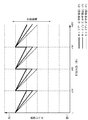
以下に図16用いて本実施形態のトナー強制消費の方法について述べる。図16は印刷枚数と印字率の積算値の関係を表している。 Hereinafter, the method of forced toner consumption according to this embodiment will be described with reference to FIG. FIG. 16 shows the relationship between the number of printed sheets and the integrated value of the printing rate.
本実施形態で用いたトナー、キャリアと現像器の構成では、画像の劣化を引き起こすことの無い印字率の閾値は2.5%であった。図中の直線Aが印字率2.5%でプリントを行なったときに印字率の積算値である。直線Aは、式1のように印字率の積算値をRとして印刷枚数Pと印字率(2.5%)の掛け算で表される。
In the configuration of the toner, carrier, and developing unit used in this embodiment, the threshold of the printing rate that does not cause image deterioration is 2.5%. The straight line A in the figure is an integrated value of the printing rate when printing is performed at a printing rate of 2.5%. The straight line A is represented by multiplying the number of printed sheets P and the printing rate (2.5%), where R is the integrated value of the printing rate as in
R=2.5・P ・・・ 式1。
R = 2.5 ·
直線Bは直線Aに対して所定の値△Xを差し引いたときの印字率の積算値である。よって以下の式2で表される。
A straight line B is an integrated value of the printing rate when a predetermined value ΔX is subtracted from the straight line A. Therefore, it is expressed by the following
R=2.5・P−△X ・・・ 式2。
R = 2.5 · P−
本実施形態では0.5%印字で画像不良が発生せずに印刷できる枚数が200枚であったことから、このときにトナー強制消費が実行されるように△Xを設定した。ここでは、△X=400%である。実際に印刷したときの印字率の積算値が直線Bを下回ったときに、トナー強制消費が実行される。トナー強制消費が実行されると印刷枚数、印字率の積算値はリセットされる。また、直線Aを上回ったときには、印刷枚数、印字率の積算値のリセットのみが行なわれる。 In this embodiment, since the number of sheets that can be printed without causing image defects with 0.5% printing is 200 sheets, ΔX is set so that the forced toner consumption is executed at this time. Here, ΔX = 400%. When the integrated value of the printing rate at the time of actual printing falls below the straight line B, the forced toner consumption is executed. When the forced toner consumption is executed, the integrated value of the number of printed sheets and the printing rate is reset. When the value exceeds the straight line A, only the integrated value of the number of printed sheets and the printing rate is reset.
実際に印刷したときの印字率の積算値を、図中破線1、2で示している。破線1は、最初の100枚は印字率0%、その後印字率5.0%のときの印刷枚数と印字率の積算値の関係を示している。このときは、印刷枚数200枚で直線Aを上回ったため、その時点でリセットがかかる。破線2は、様々な印字率の画像を出力したときの印刷枚数と印字率の積算値の関係を表している。最終的に350枚のところで印字率の積算値が直線Bを下回ったため、トナー強制消費シーケンスが実行され、それまでの印刷枚数と印字率の積算値はリセットされる。
The integrated value of the printing rate when actually printing is indicated by
このように例え印字率が0%であっても、その後高印字画像が印刷されたときにはあえてトナー強制消費動作を実施することなく現像器の状態を良好に保つことができる。このとき、印字率0%で100枚印刷した時点では、まだ画像上何の問題も発生していない。また、高印字、低印字が繰り返し印刷されるようなときであれば、画像が良好であるぎりぎりの状態まで待つことができるため、トナー強制消費動作を実施するタイミングを遅延させ、トナー強制動作を実施する回数を減らすことができる。ここでも、画像上の問題は発生することはなかった。ただし、350枚の時点でトナー強制消費を実行せずにそのまま低印字を印刷すると、350枚を過ぎて数枚後に濃度の低下が起こり画像不良を引き起こした。 In this way, even if the printing rate is 0%, the state of the developing device can be kept good without performing the forced toner consumption operation when a high-printing image is subsequently printed. At this time, when 100 sheets are printed at a printing rate of 0%, no problem has occurred on the image. In addition, when high printing and low printing are repeated, it is possible to wait until the image is in good condition, so the timing for performing the forced toner consumption operation is delayed, and the forced toner operation is performed. The number of implementations can be reduced. Again, no image problems occurred. However, if low printing was performed without executing forced toner consumption at the 350th sheet, the density decreased after 350 sheets, causing image defects.
上記のように本実施形態においては、印刷枚数に対して画質良好であるための最低の消費トナー量と実際に消費しているトナー量との差分を確認し、その差分が所定値に達したときにトナー強制消費を実施することで、必要以上にトナー強制消費動作を実行して、それによる印刷スピードの低下、トナーの浪費を抑制するとともに安定して良好な画像形成を行なえるようになる。 As described above, in the present embodiment, the difference between the minimum amount of toner consumed for good image quality and the amount of toner actually consumed is confirmed with respect to the number of printed sheets, and the difference has reached a predetermined value. Sometimes, forced toner consumption is performed, and the forced toner consumption operation is executed more than necessary, thereby reducing the printing speed and waste of toner, and enabling stable and good image formation. .
本実施形態では、プロセスカートリッジの記憶手段に印字率の閾値と差分△Xを記憶した。そのため、トナーまたはキャリアの特性に応じて印字率の閾値と差分△Xを変更することができるため、各々のトナーまたはキャリアに対応したトナー強制消費が行なえる。よって、無駄にトナーを浪費したり、頻繁に制御が入ることによる印刷時間の遅延を抑制することが可能となる。 In the present embodiment, the printing rate threshold value and the difference ΔX are stored in the storage means of the process cartridge. Therefore, since the threshold of the printing rate and the difference ΔX can be changed according to the characteristics of the toner or carrier, the forced toner consumption corresponding to each toner or carrier can be performed. Accordingly, it is possible to suppress a delay in printing time due to wasteful use of toner or frequent control.
また、ここでは記憶しておく情報量を極力少なくするため、印字率の閾値と印刷枚数の掛け算で画像が良好であるぎりぎりのトナー消費量(印字率の積算値)を計算したが、印刷枚数に対して画像が良好であるぎりぎりのトナー消費量が一意に求まるテーブルとして用意しておき、その値からトナー強制消費動作を制御することも可能である。 In order to minimize the amount of information to be stored here, the marginal toner consumption (integrated value of the printing rate) for which the image is good is calculated by multiplying the printing rate threshold value and the number of printings. However, it is also possible to prepare a table for uniquely determining the amount of toner consumption that is most favorable for the image, and to control the forced toner consumption operation from that value.
また、本実施形態においては現像装置の使用量として印刷枚数を用いる場合について説明したが、印字枚数に限らず現像剤担持体の回転数、または現像剤担持体の駆動時間を用いても良い。 In this embodiment, the case where the number of printed sheets is used as the usage amount of the developing device has been described. However, the number of rotations of the developer carrier or the driving time of the developer carrier may be used without being limited to the number of printed sheets.
なお、本実施形態の制御は図2のCPU30内に記憶されているプログラム(不図示)によって実行されるものである。
Note that the control of this embodiment is executed by a program (not shown) stored in the
当然、トナー、キャリアなどの特性の違いがあまり無く安定しているときには、プロセスカートリッジの記憶手段に印字率の閾値と差分△Xを記憶するのではなく、画像形成装置本体の記憶手段に記憶しておくことも可能である。 Naturally, when there is not much difference in characteristics such as toner and carrier, and it is stable, the threshold value of printing rate and the difference ΔX are not stored in the storage means of the process cartridge, but stored in the storage means of the image forming apparatus main body. It is also possible to keep it.
なお、本実施形態は、現像剤としてトナーとキャリアとからなるニ成分現像剤を用いた系、及び、トナーからなる一成分現像剤を用いら系に適用可能である。 The present embodiment can be applied to a system using a two-component developer composed of a toner and a carrier as a developer, and a system using a one-component developer composed of a toner.
Claims (9)
像担持体と、
前記像担持体にトナーを供給して前記像担持体上に形成された潜像を現像する現像手段と、
前記記憶手段に記憶されているトナーの特性に関する情報に基づいて、記録媒体に画像を形成することなく行うトナー消費動作を制御するための第1の閾値及び前記第1の閾値よりも小さい第2の閾値を設定する制御手段と、を有し、
前記制御手段は、前記記録媒体への画像形成が行われると画像形成を行った記録媒体の枚数を積算した積算枚数と、前記積算枚数分の画像形成を行うことにより消費された前記トナーの消費量を示す値を積算した積算値とを算出し、前記積算枚数と前記積算値を算出すると、前記積算枚数に応じた前記第1の閾値及び前記第2の閾値と前記積算値との比較を行い、前記積算値が前記第1の閾値を上回った場合は、前記トナー消費動作を行うことなく前記積算値及び前記積算枚数をリセットし、前記積算値が前記第2の閾値を下回った場合は、前記積算値及び前記積算枚数をリセットするとともに前記トナー消費動作を行うことを特徴とする画像形成装置。 An image forming apparatus that forms an image on a recording medium using a unit that includes at least a member related to image formation and a storage unit that stores information on toner characteristics,
An image carrier;
Developing means for supplying toner to the image carrier to develop a latent image formed on the image carrier;
A first threshold value for controlling a toner consumption operation to be performed without forming an image on a recording medium based on information on toner characteristics stored in the storage unit, and a second value smaller than the first threshold value. Control means for setting the threshold of
When the image formation on the recording medium is performed, the control means integrates the number of recording media on which the image has been formed, and the consumption of the toner consumed by performing the image formation for the integrated number of sheets. When the integrated value obtained by integrating the value indicating the amount is calculated, and the integrated number and the integrated value are calculated, the first threshold value and the second threshold value corresponding to the integrated number are compared with the integrated value. It was carried out, when the integrated value exceeds the first threshold value, resets the accumulated value and the accumulated number of sheets without performing the toner consumption operation, if the integrated value falls below the second threshold value The image forming apparatus, wherein the integrated value and the integrated number of sheets are reset and the toner consumption operation is performed.
前記制御手段は、前記第1の閾値及び前記第2の閾値を、前記積算枚数が増加するのに伴い値が増加するように、前記トナーの特性に応じた画像の印字率に基づく積算枚数の関数として設定することを特徴とする請求項1乃至3のいずれか1項に記載の画像形成装置。 The integrated value is an integrated value of the printing rate and the integrated number when the image is formed,
The control means sets the first threshold value and the second threshold value so that the values increase as the cumulative number increases, and the cumulative number of images based on the print rate of the image according to the characteristics of the toner. The image forming apparatus according to claim 1, wherein the image forming apparatus is set as a function.
前記像担持体上に形成された潜像にトナーを供給して現像する現像手段と、
前記トナーの特性に関する情報を記憶する記憶手段と、
前記記憶手段に記憶されているトナーの特性に関する情報に基づいて、記録媒体に画像を形成することなく行うトナー消費動作を制御するための第1の閾値及び前記第1の閾値よりも小さい第2の閾値を設定する制御手段と、
を有し、
前記制御手段は、前記記録媒体への画像形成が行われると画像形成を行った記録媒体の枚数を積算した積算枚数と、前記積算枚数分の画像形成を行うことにより消費された前記トナーの消費量を示す値を積算した積算値とを算出し、前記積算枚数と前記積算値を算出すると、前記積算枚数に応じた前記第1の閾値及び前記第2の閾値と前記積算値との比較を行い、前記積算値が前記第1の閾値を上回った場合は、前記トナー消費動作を行うことなく前記積算値及び前記積算枚数をリセットし、前記積算値が前記第2の閾値を下回った場合は、前記積算値及び前記積算枚数をリセットするとともに前記トナー消費動作を行うことを特徴とする画像形成装置。 An image carrier;
Developing means for supplying toner to the latent image formed on the image carrier and developing the latent image;
Storage means for storing information relating to the characteristics of the toner;
A first threshold value for controlling a toner consumption operation to be performed without forming an image on a recording medium based on information on toner characteristics stored in the storage unit, and a second value smaller than the first threshold value. Control means for setting a threshold value of;
Have
When the image formation on the recording medium is performed, the control unit integrates the number of recording media on which the image has been formed, and the consumption of the toner consumed by performing the image formation for the integrated number of sheets. When the integrated value obtained by integrating the value indicating the amount is calculated, and the integrated number and the integrated value are calculated, the first threshold value and the second threshold value corresponding to the integrated number are compared with the integrated value. It was carried out, when the integrated value exceeds the first threshold value, resets the accumulated value and the accumulated number of sheets without performing the toner consumption operation, if the integrated value falls below the second threshold value The image forming apparatus, wherein the integrated value and the integrated number of sheets are reset and the toner consumption operation is performed.
前記制御手段は、前記第1の閾値と前記第2の閾値とを、前記積算枚数が増加するに伴い値が増加するように、前記トナーの特性に応じた画像の印字率に基づく積算枚数の関数として設定することを特徴とする請求項7に記載の画像形成装置。 The integrated value is an integrated value of the printing rate and the integrated number when the image is formed,
The control means sets the first threshold value and the second threshold value so that the value increases as the cumulative number increases, and the cumulative number of images based on the print rate of the image according to the characteristics of the toner. The image forming apparatus according to claim 7, wherein the image forming apparatus is set as a function.
Priority Applications (2)
| Application Number | Priority Date | Filing Date | Title |
|---|---|---|---|
| JP2004207605A JP4618775B2 (en) | 2003-07-31 | 2004-07-14 | Image forming apparatus |
| US10/896,898 US7095966B2 (en) | 2003-07-31 | 2004-07-23 | Image forming apparatus and unit, and storage medium mounted in the unit |
Applications Claiming Priority (2)
| Application Number | Priority Date | Filing Date | Title |
|---|---|---|---|
| JP2003204820 | 2003-07-31 | ||
| JP2004207605A JP4618775B2 (en) | 2003-07-31 | 2004-07-14 | Image forming apparatus |
Publications (3)
| Publication Number | Publication Date |
|---|---|
| JP2005062840A JP2005062840A (en) | 2005-03-10 |
| JP2005062840A5 JP2005062840A5 (en) | 2007-08-23 |
| JP4618775B2 true JP4618775B2 (en) | 2011-01-26 |
Family
ID=34106874
Family Applications (1)
| Application Number | Title | Priority Date | Filing Date |
|---|---|---|---|
| JP2004207605A Expired - Fee Related JP4618775B2 (en) | 2003-07-31 | 2004-07-14 | Image forming apparatus |
Country Status (2)
| Country | Link |
|---|---|
| US (1) | US7095966B2 (en) |
| JP (1) | JP4618775B2 (en) |
Families Citing this family (38)
| Publication number | Priority date | Publication date | Assignee | Title |
|---|---|---|---|---|
| CN100421037C (en) * | 2003-01-23 | 2008-09-24 | 株式会社理光 | Developing starting method, developing device and processing card box |
| DE102004005964A1 (en) * | 2004-02-06 | 2005-09-08 | OCé PRINTING SYSTEMS GMBH | Control device and method for controlling an electrophotographic printer or copier |
| JP2006243115A (en) * | 2005-03-01 | 2006-09-14 | Konica Minolta Business Technologies Inc | Image forming apparatus |
| JP2006313307A (en) * | 2005-04-06 | 2006-11-16 | Konica Minolta Business Technologies Inc | Image forming apparatus |
| JP2006337469A (en) * | 2005-05-31 | 2006-12-14 | Kyocera Mita Corp | Image forming apparatus |
| JP4844059B2 (en) * | 2005-09-15 | 2011-12-21 | 富士ゼロックス株式会社 | Image forming apparatus and image output apparatus used therefor |
| JP2007133122A (en) * | 2005-11-10 | 2007-05-31 | Ricoh Co Ltd | Developing device and image forming apparatus |
| JP2007264477A (en) * | 2006-03-29 | 2007-10-11 | Kyocera Mita Corp | Image forming apparatus |
| JP2007264510A (en) * | 2006-03-29 | 2007-10-11 | Canon Inc | Image forming apparatus |
| JP2008158196A (en) * | 2006-12-22 | 2008-07-10 | Kyocera Mita Corp | Image forming apparatus |
| JP5110899B2 (en) * | 2007-02-19 | 2012-12-26 | キヤノン株式会社 | Information processing apparatus and information processing method |
| US7729623B2 (en) * | 2007-06-07 | 2010-06-01 | Samsung Electronics Co., Ltd. | Image forming apparatus and image forming method thereof |
| US7844191B2 (en) * | 2007-06-28 | 2010-11-30 | Ricoh Company Limited | Image forming apparatus and image forming method performed by the image forming apparatus |
| JP5091572B2 (en) * | 2007-07-12 | 2012-12-05 | 京セラドキュメントソリューションズ株式会社 | Image forming method and image forming apparatus |
| JP5094278B2 (en) * | 2007-08-27 | 2012-12-12 | 京セラドキュメントソリューションズ株式会社 | Image forming apparatus |
| US8099002B2 (en) * | 2007-11-15 | 2012-01-17 | Kabushiki Kaisha Toshiba | Developing device of image forming apparatus using a toner and carrier mixture |
| JP4586885B2 (en) * | 2008-05-26 | 2010-11-24 | コニカミノルタビジネステクノロジーズ株式会社 | Image forming apparatus, image forming apparatus control method, and image forming apparatus control program |
| JP5584522B2 (en) * | 2010-06-02 | 2014-09-03 | キヤノン株式会社 | Image forming apparatus and gradation adjustment method thereof |
| JP5171890B2 (en) * | 2010-06-23 | 2013-03-27 | シャープ株式会社 | Developing transport device, developing device including the same, toner cartridge, and cleaning unit |
| JP5721364B2 (en) | 2010-08-19 | 2015-05-20 | キヤノン株式会社 | Image forming apparatus |
| US20120207489A1 (en) * | 2011-02-11 | 2012-08-16 | Eric Carl Stelter | Replenishing toner used from electrophotographic developer |
| JP5383750B2 (en) | 2011-06-29 | 2014-01-08 | キヤノン株式会社 | Image forming apparatus |
| JP5979475B2 (en) * | 2012-03-05 | 2016-08-24 | 株式会社リコー | Image forming apparatus |
| JP2013235068A (en) * | 2012-05-07 | 2013-11-21 | Canon Inc | Image formation apparatus, image processing apparatus and control method thereof, and program |
| JP5945944B2 (en) * | 2012-07-20 | 2016-07-05 | 富士ゼロックス株式会社 | Image forming apparatus |
| JP5983357B2 (en) * | 2012-11-27 | 2016-08-31 | 富士ゼロックス株式会社 | Developing device and image forming apparatus using the same |
| JP5920731B2 (en) * | 2013-08-30 | 2016-05-18 | 京セラドキュメントソリューションズ株式会社 | Image forming apparatus |
| JP2016062023A (en) * | 2014-09-19 | 2016-04-25 | キヤノン株式会社 | Development apparatus |
| JP6468830B2 (en) | 2014-12-12 | 2019-02-13 | キヤノン株式会社 | Image forming apparatus |
| JP6138177B2 (en) * | 2015-01-21 | 2017-05-31 | 京セラドキュメントソリューションズ株式会社 | Developing device, image forming apparatus |
| JP6736933B2 (en) * | 2016-03-24 | 2020-08-05 | コニカミノルタ株式会社 | Image forming device |
| JP6493319B2 (en) * | 2016-06-28 | 2019-04-03 | 京セラドキュメントソリューションズ株式会社 | Image forming apparatus and refresh processing control method |
| JP6172593B2 (en) * | 2016-07-07 | 2017-08-02 | 株式会社リコー | Image forming apparatus |
| JP6828657B2 (en) * | 2017-11-08 | 2021-02-10 | 京セラドキュメントソリューションズ株式会社 | Image forming device and image forming method |
| US10761454B2 (en) * | 2018-02-23 | 2020-09-01 | Kabushiki Kaisha Toshiba | System and method for determining toner cartridge authenticity via toner patterns |
| JP2020144336A (en) * | 2019-03-08 | 2020-09-10 | 京セラドキュメントソリューションズ株式会社 | Image forming apparatus |
| JP2020144337A (en) * | 2019-03-08 | 2020-09-10 | 京セラドキュメントソリューションズ株式会社 | Image forming apparatus |
| JP2019135553A (en) * | 2019-04-12 | 2019-08-15 | キヤノン株式会社 | Image forming apparatus |
Citations (2)
| Publication number | Priority date | Publication date | Assignee | Title |
|---|---|---|---|---|
| JP2002268476A (en) * | 2001-03-08 | 2002-09-18 | Canon Inc | Image forming apparatus, cartridge, and image forming system |
| JP2003162102A (en) * | 2001-11-26 | 2003-06-06 | Oki Data Corp | Image forming device and control method |
Family Cites Families (1)
| Publication number | Priority date | Publication date | Assignee | Title |
|---|---|---|---|---|
| US6792218B2 (en) * | 2002-06-11 | 2004-09-14 | Lexmark International, Inc. | Method of compensating for low toner consumption |
-
2004
- 2004-07-14 JP JP2004207605A patent/JP4618775B2/en not_active Expired - Fee Related
- 2004-07-23 US US10/896,898 patent/US7095966B2/en not_active Expired - Lifetime
Patent Citations (2)
| Publication number | Priority date | Publication date | Assignee | Title |
|---|---|---|---|---|
| JP2002268476A (en) * | 2001-03-08 | 2002-09-18 | Canon Inc | Image forming apparatus, cartridge, and image forming system |
| JP2003162102A (en) * | 2001-11-26 | 2003-06-06 | Oki Data Corp | Image forming device and control method |
Also Published As
| Publication number | Publication date |
|---|---|
| US20050025506A1 (en) | 2005-02-03 |
| JP2005062840A (en) | 2005-03-10 |
| US7095966B2 (en) | 2006-08-22 |
Similar Documents
| Publication | Publication Date | Title |
|---|---|---|
| JP4618775B2 (en) | Image forming apparatus | |
| US7430378B2 (en) | Image forming apparatus setting an image forming condition based on characteristics of a cartridge, cartridge used in the image forming apparatus, and storage medium mounted on the cartridge | |
| KR101509850B1 (en) | Image forming apparatus | |
| JP4630693B2 (en) | Image forming method | |
| US10168643B2 (en) | Developing apparatus having developer distribution control | |
| JP5538934B2 (en) | Image forming apparatus | |
| JP2005283685A (en) | Image forming apparatus | |
| JP4920908B2 (en) | Image forming apparatus | |
| JP4467944B2 (en) | Developer carrier and developing device | |
| JP2004177928A (en) | Image forming apparatus and image forming method | |
| JP2004170956A (en) | Image forming apparatus, cartridge, image forming system and memory medium for cartridge | |
| JP5822609B2 (en) | Image forming apparatus | |
| JP4822822B2 (en) | Image forming apparatus | |
| JP6373064B2 (en) | Image forming apparatus | |
| JP4641404B2 (en) | Image forming apparatus | |
| JP5297956B2 (en) | Image forming apparatus | |
| JP2010048859A (en) | Image forming apparatus | |
| JP5538935B2 (en) | Image forming apparatus | |
| JP2010066420A (en) | Image forming apparatus | |
| JP4560354B2 (en) | Image forming apparatus | |
| JP2005338636A (en) | Cleaner-less type image forming apparatus | |
| JP2000089554A (en) | Image forming device | |
| JP4776979B2 (en) | Image forming apparatus | |
| JP3595662B2 (en) | Image forming device | |
| JP2005157124A (en) | Image forming apparatus, control method of same, and process cartridge |
Legal Events
| Date | Code | Title | Description |
|---|---|---|---|
| A521 | Written amendment |
Free format text: JAPANESE INTERMEDIATE CODE: A523 Effective date: 20070710 |
|
| A621 | Written request for application examination |
Free format text: JAPANESE INTERMEDIATE CODE: A621 Effective date: 20070710 |
|
| RD03 | Notification of appointment of power of attorney |
Free format text: JAPANESE INTERMEDIATE CODE: A7423 Effective date: 20070710 |
|
| A977 | Report on retrieval |
Free format text: JAPANESE INTERMEDIATE CODE: A971007 Effective date: 20100312 |
|
| A131 | Notification of reasons for refusal |
Free format text: JAPANESE INTERMEDIATE CODE: A131 Effective date: 20100319 |
|
| A521 | Written amendment |
Free format text: JAPANESE INTERMEDIATE CODE: A523 Effective date: 20100518 |
|
| A131 | Notification of reasons for refusal |
Free format text: JAPANESE INTERMEDIATE CODE: A131 Effective date: 20100716 |
|
| A521 | Written amendment |
Free format text: JAPANESE INTERMEDIATE CODE: A523 Effective date: 20100914 |
|
| TRDD | Decision of grant or rejection written | ||
| A01 | Written decision to grant a patent or to grant a registration (utility model) |
Free format text: JAPANESE INTERMEDIATE CODE: A01 Effective date: 20101022 |
|
| A01 | Written decision to grant a patent or to grant a registration (utility model) |
Free format text: JAPANESE INTERMEDIATE CODE: A01 |
|
| A61 | First payment of annual fees (during grant procedure) |
Free format text: JAPANESE INTERMEDIATE CODE: A61 Effective date: 20101025 |
|
| FPAY | Renewal fee payment (event date is renewal date of database) |
Free format text: PAYMENT UNTIL: 20131105 Year of fee payment: 3 |
|
| R150 | Certificate of patent or registration of utility model |
Free format text: JAPANESE INTERMEDIATE CODE: R150 |
|
| LAPS | Cancellation because of no payment of annual fees |