JP4617359B2 - Linear ultrasonic piezoelectric motor - Google Patents
Linear ultrasonic piezoelectric motor Download PDFInfo
- Publication number
- JP4617359B2 JP4617359B2 JP2007528622A JP2007528622A JP4617359B2 JP 4617359 B2 JP4617359 B2 JP 4617359B2 JP 2007528622 A JP2007528622 A JP 2007528622A JP 2007528622 A JP2007528622 A JP 2007528622A JP 4617359 B2 JP4617359 B2 JP 4617359B2
- Authority
- JP
- Japan
- Prior art keywords
- piezoelectric
- plate
- piezoelectric motor
- resonance plate
- motor
- Prior art date
- Legal status (The legal status is an assumption and is not a legal conclusion. Google has not performed a legal analysis and makes no representation as to the accuracy of the status listed.)
- Active
Links
- 230000005284 excitation Effects 0.000 claims description 29
- 239000000463 material Substances 0.000 claims description 12
- 238000000034 method Methods 0.000 claims description 3
- 239000011248 coating agent Substances 0.000 claims description 2
- 238000000576 coating method Methods 0.000 claims description 2
- 230000000295 complement effect Effects 0.000 claims description 2
- 230000002441 reversible effect Effects 0.000 claims description 2
- 238000002604 ultrasonography Methods 0.000 abstract 1
- 239000000919 ceramic Substances 0.000 description 4
- 238000010586 diagram Methods 0.000 description 3
- 230000010355 oscillation Effects 0.000 description 3
- 229910000831 Steel Inorganic materials 0.000 description 2
- 230000003321 amplification Effects 0.000 description 2
- 238000004519 manufacturing process Methods 0.000 description 2
- 238000003199 nucleic acid amplification method Methods 0.000 description 2
- 230000010363 phase shift Effects 0.000 description 2
- 239000010959 steel Substances 0.000 description 2
- 230000002159 abnormal effect Effects 0.000 description 1
- 238000004026 adhesive bonding Methods 0.000 description 1
- 230000002411 adverse Effects 0.000 description 1
- 229910002113 barium titanate Inorganic materials 0.000 description 1
- JRPBQTZRNDNNOP-UHFFFAOYSA-N barium titanate Chemical compound [Ba+2].[Ba+2].[O-][Ti]([O-])([O-])[O-] JRPBQTZRNDNNOP-UHFFFAOYSA-N 0.000 description 1
- 238000005452 bending Methods 0.000 description 1
- 239000013078 crystal Substances 0.000 description 1
- 230000001419 dependent effect Effects 0.000 description 1
- 238000005516 engineering process Methods 0.000 description 1
- 238000001914 filtration Methods 0.000 description 1
- 239000011521 glass Substances 0.000 description 1
- 238000010438 heat treatment Methods 0.000 description 1
- 229910052451 lead zirconate titanate Inorganic materials 0.000 description 1
- HFGPZNIAWCZYJU-UHFFFAOYSA-N lead zirconate titanate Chemical compound [O-2].[O-2].[O-2].[O-2].[O-2].[Ti+4].[Zr+4].[Pb+2] HFGPZNIAWCZYJU-UHFFFAOYSA-N 0.000 description 1
- GQYHUHYESMUTHG-UHFFFAOYSA-N lithium niobate Chemical compound [Li+].[O-][Nb](=O)=O GQYHUHYESMUTHG-UHFFFAOYSA-N 0.000 description 1
- 230000007774 longterm Effects 0.000 description 1
- 239000000696 magnetic material Substances 0.000 description 1
- 229910052751 metal Inorganic materials 0.000 description 1
- 239000002184 metal Substances 0.000 description 1
- 238000012986 modification Methods 0.000 description 1
- 230000004048 modification Effects 0.000 description 1
- 230000003287 optical effect Effects 0.000 description 1
- 239000010453 quartz Substances 0.000 description 1
- VYPSYNLAJGMNEJ-UHFFFAOYSA-N silicon dioxide Inorganic materials O=[Si]=O VYPSYNLAJGMNEJ-UHFFFAOYSA-N 0.000 description 1
- 238000005549 size reduction Methods 0.000 description 1
- 239000010409 thin film Substances 0.000 description 1
Images


Classifications
-
- H—ELECTRICITY
- H02—GENERATION; CONVERSION OR DISTRIBUTION OF ELECTRIC POWER
- H02N—ELECTRIC MACHINES NOT OTHERWISE PROVIDED FOR
- H02N2/00—Electric machines in general using piezoelectric effect, electrostriction or magnetostriction
- H02N2/02—Electric machines in general using piezoelectric effect, electrostriction or magnetostriction producing linear motion, e.g. actuators; Linear positioners ; Linear motors
- H02N2/026—Electric machines in general using piezoelectric effect, electrostriction or magnetostriction producing linear motion, e.g. actuators; Linear positioners ; Linear motors by pressing one or more vibrators against the driven body
-
- H—ELECTRICITY
- H02—GENERATION; CONVERSION OR DISTRIBUTION OF ELECTRIC POWER
- H02N—ELECTRIC MACHINES NOT OTHERWISE PROVIDED FOR
- H02N2/00—Electric machines in general using piezoelectric effect, electrostriction or magnetostriction
- H02N2/0005—Electric machines in general using piezoelectric effect, electrostriction or magnetostriction producing non-specific motion; Details common to machines covered by H02N2/02 - H02N2/16
- H02N2/001—Driving devices, e.g. vibrators
- H02N2/002—Driving devices, e.g. vibrators using only longitudinal or radial modes
-
- H—ELECTRICITY
- H02—GENERATION; CONVERSION OR DISTRIBUTION OF ELECTRIC POWER
- H02N—ELECTRIC MACHINES NOT OTHERWISE PROVIDED FOR
- H02N2/00—Electric machines in general using piezoelectric effect, electrostriction or magnetostriction
- H02N2/0005—Electric machines in general using piezoelectric effect, electrostriction or magnetostriction producing non-specific motion; Details common to machines covered by H02N2/02 - H02N2/16
- H02N2/005—Mechanical details, e.g. housings
- H02N2/0065—Friction interface
-
- H—ELECTRICITY
- H02—GENERATION; CONVERSION OR DISTRIBUTION OF ELECTRIC POWER
- H02N—ELECTRIC MACHINES NOT OTHERWISE PROVIDED FOR
- H02N2/00—Electric machines in general using piezoelectric effect, electrostriction or magnetostriction
- H02N2/0005—Electric machines in general using piezoelectric effect, electrostriction or magnetostriction producing non-specific motion; Details common to machines covered by H02N2/02 - H02N2/16
- H02N2/0075—Electrical details, e.g. drive or control circuits or methods
- H02N2/008—Means for controlling vibration frequency or phase, e.g. for resonance tracking
Landscapes
- General Electrical Machinery Utilizing Piezoelectricity, Electrostriction Or Magnetostriction (AREA)
- Lens Barrels (AREA)
- Reciprocating, Oscillating Or Vibrating Motors (AREA)
Abstract
Description
本発明は、特許請求項1の前提部分に記載されている、プレート状の長方形の共振板と摩擦接触状態にあって摩擦面は上記共振板の長手方向の狭い側面の少なくとも一方によって具現される移動エレメントと、上記共振板の長手方向の広い側面に配置される、音響振動を生成するための2つの電極とを備えるリニア超音波圧電モータに関する。
The present invention is in frictional contact with a plate-shaped rectangular resonance plate described in the premise of
米国特許第4,978,882号から、圧電励振の原理に従って環状振動子内で閉鎖型の導波路として動作するリニア超音波モータが知られている。このようなモータの構造は極めて複雑であり、幾つかの圧電素子は、例えば接着によって環状振動子へ粘着式に固定されなければならない。従って、このようなモータは製造費用が極めて高く、小型化は限定的にしか行えない。 From US Pat. No. 4,978,882 a linear ultrasonic motor is known which operates as a closed waveguide in an annular vibrator according to the principle of piezoelectric excitation. The structure of such a motor is very complex, and some piezoelectric elements must be adhesively fixed to the annular vibrator, for example by gluing. Therefore, such a motor is very expensive to manufacture and can only be reduced in size.
米国特許第5,672,930号による最新技術は、棒状振動子、即ち開放型の導波路における移動超音波の励振を使用する超音波モータを包含している。このようなモータの欠点は、対称定在波は開放型の導波路において移動波の励起と同時的に励起され、移動波の励起はモータの摩擦接触作用に悪影響を与えることから、開放型の導波路において正確に移動する超音波を励起することが実際には不可能である、という事実にある。延てはこれは、摩擦面及びモータ全体の各々の著しい加熱、及び高い雑音レベルをもたらす。さらに、上記最新技術によるこれらのモータは極めて高い励振電圧を必要とし、製造費用が高く、小型化は困難である。 The state of the art according to U.S. Pat. No. 5,672,930 includes a bar vibrator, ie an ultrasonic motor using excitation of moving ultrasonic waves in an open waveguide. The disadvantage of such a motor is that the symmetrical standing wave is excited simultaneously with the excitation of the moving wave in the open waveguide, and the excitation of the moving wave adversely affects the frictional contact action of the motor. The fact is that it is practically impossible to excite ultrasonic waves that move accurately in the waveguide. This in turn results in significant heating and high noise levels on each of the friction surfaces and the entire motor. Furthermore, these motors according to the state-of-the-art technology require extremely high excitation voltages, are expensive to manufacture, and are difficult to miniaturize.
最も明白なソリューションは、例えばDE 199 45 042 C2による圧電超音波モータによって特徴づけられる。このようなモータでは、定在的な縦波及び屈曲波は圧電板状の共振器内で同時に励起される。両波が干渉する結果、共振器に配置される衝撃エレメントには楕円動作が加わる。この衝撃エレメントは、同動作を、ボールベアリングにより支持されかつ衝撃エレメントへ押し当てられるさらなる移動エレメントへ伝達する。しかしながら、この場合は、特に財政面で比較的高価なボールベアリングの使用が欠点である。 The most obvious solution is for example characterized by a piezoelectric ultrasonic motor according to DE 199 45 042 C2. In such a motor, standing longitudinal waves and bending waves are simultaneously excited in a piezoelectric plate resonator. As a result of the interference between the two waves, an elliptical motion is applied to the impact element disposed in the resonator. This impact element transmits this movement to a further moving element supported by a ball bearing and pressed against the impact element. However, in this case, the use of a relatively expensive ball bearing, particularly in financial terms, is a disadvantage.
大幅に安価なスライドベアリングの使用は、アクチュエータによって引き起こされる回転力または摩擦接触を介して伝達される回転力の各々に比肩し得るベアリング内の摩擦損失を伴う。そのため、本来明白であるはずのボールベアリングの放棄には問題がある。別の問題はボールベアリングが磁性材料で具現されることにあり、よってこのようなモータを非磁性アプリケーションに使用することはできない。 The use of significantly less expensive slide bearings involves friction losses in the bearing that can be compared to each of the rotational forces caused by the actuators or transmitted via frictional contact. Therefore, there is a problem in abandoning ball bearings that should be obvious. Another problem is that the ball bearing is implemented with a magnetic material, so such a motor cannot be used for non-magnetic applications.
従って、本発明の目的は、上述の問題点を基礎として、プレート状の長方形の共振板と摩擦接触状態にある移動エレメントを備える、さらに開発されたリニア超音波圧電モータを提供することにあり、この場合のモータは極く小型の物理的サイズを有し、全体構造は単純でありかつ少数の構成要素による製造が可能である。 Accordingly, an object of the present invention is to provide a further developed linear ultrasonic piezoelectric motor including a moving element that is in frictional contact with a plate-like rectangular resonance plate based on the above-described problems. The motor in this case has a very small physical size, the overall structure is simple and can be manufactured with a small number of components.
また、生成されるべきモータの励振電圧は小さいものになり、効率の増大が達成される。提供されるべきモータの新規構造設計により、これらは、特に小型X−Yテーブル、マイクロロボットまたはこれらに類似するメカトロ装置等の微細位置決め装置における使用に適するものとなる。 In addition, the excitation voltage of the motor to be generated is small, and an increase in efficiency is achieved. The new structural design of the motors to be provided makes them particularly suitable for use in micropositioning devices such as small XY tables, microrobots or similar mechatronic devices.
上記目的に対する本発明によるソリューションは、特許請求項1及び少なくとも有効な実施形態及び進歩を表示する従属請求項に記載されている特徴の組み合わせに従ったリニア超音波圧電モータによって達成される。
The solution according to the invention for the above object is achieved by a linear ultrasonic piezoelectric motor in accordance with the combination of the features described in
本発明によれば、音響振動を生成するための発生器は、共振板を対称的に横断する平面に対して非対称に配置され、励起されると非対称空間定在波を発生させる対向する2つの電極を備える。 According to the present invention, the generator for generating acoustic vibrations is arranged asymmetrically with respect to a plane symmetrically traversing the resonant plate and, when excited, generates two opposed asymmetric spatial standing waves. With electrodes.
必要な振動を生成するための発生器のこのような構造は、前述の非対称空間波の励振を許容するだけでなく、摩擦接触の長さを大幅に増大させることができ、振動子上の摩擦面及び移動エレメント上の摩擦面の単純な配置を実現することができる。 Such a structure of the generator for generating the necessary vibrations not only allows the aforementioned asymmetric spatial wave excitation, but can also greatly increase the length of the friction contact, and the friction on the vibrator A simple arrangement of the friction surface on the surface and the moving element can be realized.
対称的な横断面の両側における音響振動を生成するための発生器の上記配置は、発生器の切替えによる移動エレメントの反転動作の達成を可能にし、よって発振動作を単純に生成することができる。 The above arrangement of generators for generating acoustic vibrations on both sides of a symmetric cross section makes it possible to achieve a reversing operation of the moving element by switching the generator, and thus an oscillation operation can simply be generated.
長手方向の狭い側面の少なくとも一方は、案内溝、案内チャネルまたは案内レールを備えてもよく、上記案内溝、案内チャネルまたは案内レールは耐摩耗性のコーティングを有するか、このような材料で製造される。 At least one of the narrow longitudinal sides may be provided with a guide groove, guide channel or guide rail, said guide groove, guide channel or guide rail having a wear-resistant coating or made of such a material. The
移動エレメントは、長手方向の狭い両側へ機械的かつ機能的に接続されるばね挟みとして具現されてもよい。 The moving element may be embodied as a spring clamp that is mechanically and functionally connected to both narrow sides in the longitudinal direction.
ばね挟みは、例えばU字形またはV字形であってもよく、自由な脚で摩擦エレメントを運び、摩擦エレメントは案内溝、案内チャネルまたは案内レールの各々との相補形状を有する。 The spring clamp may be U-shaped or V-shaped, for example, and carries the friction element with a free leg, the friction element having a complementary shape with each of the guide groove, guide channel or guide rail.
本発明の一実施形態では、ばね挟みの脚は、具体的にはレンズである移動オブジェクトのホルダとして形成される取付け部分または取付けセクションを含む。 In one embodiment of the invention, the spring clamp leg includes a mounting portion or section formed as a holder for a moving object, in particular a lens.
超音波圧電モータの共振板はモノリシックな圧電材料または圧電体で製造されてもよく、よって、この圧電体の構成要素は、対応する励振電極により音響振動を生成するための生成器の機能を実行する。 The resonant plate of an ultrasonic piezoelectric motor may be made of a monolithic piezoelectric material or a piezoelectric body, so that this piezoelectric component performs the function of a generator to generate acoustic vibrations with a corresponding excitation electrode To do.
或いは、共振板は非圧電材料で製造することも可能であり、この場合、音響振動を生成するための発生器は共振板へ機械的に固定されて接続される。 Alternatively, the resonant plate can be made of a non-piezoelectric material, in which case the generator for generating acoustic vibrations is mechanically fixed and connected to the resonant plate.
先に説明したようなリニア超音波圧電モータを電気的に動作させるための方法では、励振源は、好適には、固定動作周波数を有する電流フィードバック自動調整型発生器として具現され、上記動作周波数は、非対称空間定在波の励振を引き起こす圧電振動子の共振周波数によって予め定義される。 In the method for electrically operating a linear ultrasonic piezoelectric motor as described above, the excitation source is preferably embodied as a current feedback self-adjusting generator having a fixed operating frequency, wherein the operating frequency is , Pre-defined by the resonance frequency of the piezoelectric vibrator that causes excitation of the asymmetric spatial standing wave.
従って、超音波圧電モータの振動子は、好適には少なくとも1つの滑らかな摩擦面を有する長方形である共振板を有する。移動エレメントは、振動子の摩擦面へ機能的に接続されている少なくとも1つの摩擦エレメントを含む。これにより、振動子の音響振動を生成するための発生器、延ては電極も、共振板を横断する対称面に対して非対称に配置される。このような配置に基づいて、超音波モータが電気的に励起されると、振動子内に非対称の音響定在空間波が発生し、これが移動エレメントを駆動する。 Therefore, the transducer of the ultrasonic piezoelectric motor has a resonant plate that is preferably rectangular with at least one smooth friction surface. The moving element includes at least one friction element operatively connected to the friction surface of the transducer. As a result, the generator for generating the acoustic vibration of the vibrator, and thus the electrode, are also arranged asymmetrically with respect to the plane of symmetry crossing the resonance plate. Based on such an arrangement, when the ultrasonic motor is electrically excited, an asymmetric acoustic standing spatial wave is generated in the vibrator, which drives the moving element.
ある実施形態では、本発明によるモータは、超音波振動子が2つの音響振動発生器を有するように構成されてもよく、この場合、上記発生器の各々は共振板を横断する対称面に対して非対称に配置され、かつさらに、結果的に先に説明した移動エレメントの反転動作が可能になるように、一方またはもう一方の発生器の何れかを必要な電気励振源へ接続するための切換えスイッチが装備される。 In an embodiment, the motor according to the invention may be configured such that the ultrasonic transducer has two acoustic vibration generators, where each of the generators is relative to a plane of symmetry that traverses the resonant plate. Switching to connect either one or the other generator to the required electrical excitation source so that it can be arranged asymmetrically and, as a result, allows the reversal action of the moving element described above. Equipped with a switch.
本発明によるモータの摩擦面は、振動板の長手方向の狭い側面に位置決めされる案内チャネルの一方または双方へ配置されてもよい。さらに、摩擦面は、同じく振動板の長手方向の狭い2側面の一方に位置決めされる案内レール上へ配置されてもよい。これらは共に、移動部分のその動作に対して垂直方向への固定を可能にする。 The friction surface of the motor according to the invention may be arranged on one or both of the guide channels which are positioned on the narrow side in the longitudinal direction of the diaphragm. Further, the friction surface may be disposed on a guide rail that is positioned on one of two narrow side surfaces in the longitudinal direction of the diaphragm. Both of these allow the moving part to be fixed vertically to its movement.
耐用年数を延ばしかつ長期安定性を向上させるために、本発明的モータの各実施形態では、案内チャネルまたは案内レールの表面に耐摩耗性の層または中間層が装備されてもよく、実際の摩擦層は後にこの上に装着される。 In order to extend the service life and improve long-term stability, each embodiment of the inventive motor may be provided with a wear-resistant layer or intermediate layer on the surface of the guide channel or guide rail, and the actual friction The layer is later mounted on this.
本発明的モータの一実施形態では、移動エレメントとして2部形式のソリューションが選択されていて、各部分は、特定のリニアガイドを使用する必要がないように、対向する部分に対して摩擦面の方向へばね式に取り付けられる。 In one embodiment of the inventive motor, a two-part solution has been selected as the moving element, and each part has a friction surface against the opposite part so that a specific linear guide need not be used. It is spring-loaded in the direction.
先に述べた自動調整型発生器(オートジェネレータ)の実施形態の場合は、超音波モータの共振周波数の継続的追跡が可能であり、よって、この態様下でもアッセンブリ全体の機能安定性の向上が達成される。 In the case of the embodiment of the self-adjusting generator (auto generator) described above, it is possible to continuously track the resonance frequency of the ultrasonic motor. Therefore, even in this aspect, the functional stability of the entire assembly can be improved. Achieved.
以下、様々な例示的実施形態により、かつ諸図を参照して、本発明をさらに詳しく説明する。 In the following, the invention will be described in more detail by means of various exemplary embodiments and with reference to the figures.
図1によれば、本発明によるモータは、振動防止用の裏当て2によってホルダ3内に位置決めされる超音波振動子1を備える。さらに、上記振動子と摩擦接触状態にある移動エレメント4が示されている。超音波振動子1は、長方形の共振板5及び音響振動を生成するための1つまたは2つの発生器6で形成される。
According to FIG. 1, the motor according to the invention comprises an
基本的には、本発明によるモータの2つの構造的変形が実現可能である。 Basically, two structural variants of the motor according to the invention are feasible.
第1の実施形態では、共振板5は完全に、例えばチタン酸ジルコン酸鉛、チタン酸バリウム、結晶石英、ニオブ酸リチウムからなる圧電材料、またはこれらに類似する圧電材料で製造される。
In the first embodiment, the
音響振動の発生器6は各々、励振電極7(図1)と、共通の背後電極8とを含む。これら双方の電極は、共振板5の長手方向の広い側面9及び10に位置決めされる。この実施形態では、各音響振動発生器6が圧電板5の一部を表す。振動子自体は、モノリシックな(単一の)圧電体として形成される。
Each of the
修正されたモータの第2の実施形態では、振動子1は組み立て式の振動子として形成され、複数の発生器6が圧電板5に連結される。
In the second embodiment of the modified motor, the
これら双方の実施形態では、圧電板5の長手方向の狭い側面11に案内チャネル12(図1)または案内レール30(図11)の何れかが装備される。摩擦面13は、耐摩耗性の層14上へ直接装備される。
In both these embodiments, either the guide channel 12 (FIG. 1) or the guide rail 30 (FIG. 11) is provided on the
モータの摩擦接点の異常な摩耗を防止するために、上記耐摩耗性の層14は、案内チャネル12または案内レール30の表面へ金属、セラミック、ガラスまたは別の個々に最適化された材料で製造される耐摩耗性の薄膜として装着される。
In order to prevent abnormal wear of the friction contacts of the motor, the wear-
モータが案内レールを伴って実現されれば、上記耐摩耗性の層は、圧電板5の長手方向の狭い側面11上へ接着により装着される薄板であってもよい。
If the motor is realized with a guide rail, the wear-resistant layer may be a thin plate that is mounted on the
モータの移動エレメント4は2つの部分15で構成されてもよく、その各々には、案内チャネル12内に位置決めされる摩擦エレメント16が装備される。さらに、部分15の各々は、摩擦エレメント16が摩擦面13を弾性的に押すように、ばね17によってもう一方の部分15へばね荷重式に固定されてもよい。この場合、ばね17は、例えばアジャスタ、磁気ヘッドまたは類似デバイスである移動エレメントのホルダとして機能してもよい。
The
図2は、電気励振源18を有する振動子の例示的な配線スキームを示す。本発明的モータの機能原理に従って、電気励振源18は、移動エレメント4の動作方向に応じて対応する発生器6へ接続される。次いで、所望される動作方向に応じて、切換えスイッチ19により、発生器の切換が行われる。
FIG. 2 shows an exemplary wiring scheme for a vibrator having an
図3及び4は、振動子1の異なる構造的変形を示す。振動子1の構造及びモータの動作モードを説明するために、図3及び4は、圧電板5を横断する対称面Sを示している。上記対称面は圧電板とその長さLの真ん中で交差し、大きい側面9に対して垂直に伸長しかつ長手方向の狭い側面11に対しても同じく垂直に示されている。
3 and 4 show different structural deformations of the
振動子1の、音響振動を生成するため発生器6は、対称面Sに対して非対称であり、即ちこれは、対応する動作方向に関連して片側だけに配置される。
The
図3は、非対称性の一次音響空間波を励振するための振動子1を示す。この場合、圧電板の長さLの高さHに対する割合は、ほぼ2乃至3である(L/H=2乃至3)。
FIG. 3 shows a
図1によれば、細長い振動子を提供することも可能であり、即ち、例えば6次である、より高次の非対称空間定在波を励振することも可能である。波の次数は、圧電板5の長さによって決定される。これは、L=n・K、但しn=4,6,8...、K=0.7乃至1・H、という割合から選択される。
According to FIG. 1, it is also possible to provide an elongated transducer, ie it is possible to excite higher order asymmetric spatial standing waves, for example the sixth order. The order of the wave is determined by the length of the
図5では、振動子1の圧電板5の歪位置20及び21、即ち非対称の一次空間定在波が励振されている場合が示されている。これらの図は、時間的に発振周期の半分T/2だけ隔たる歪の境界例に対応している。
In FIG. 5, the strain positions 20 and 21 of the
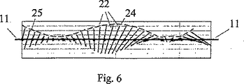
図6は、圧電板5の長手方向の狭い側面11上へ位置づけられる点23の動作経路22、即ち、図5に示す一次定在波が励振されている場合を示す。本図から、一次定在波は振幅曲線25上で最大値24を有することが分る。
FIG. 6 shows an
図7は、アクティブな機械力成分を基礎とするモータの動作モードを示す。 FIG. 7 shows the operating mode of the motor based on the active mechanical force component.
振動子1の片側は、防振用の裏当て26を介して固定式の土台27上に支持される。移動エレメント4は、力Fdにより、振動子1の反対側の側面11へ押し付けられる。長手方向の狭い側面11には摩擦面13が備えられ、移動エレメント4には摩擦エレメント16が備えられている。振動子が励振されると、移動エレメント4へ作用する力に影響されて結果的に生じる力Fsが、移動エレメントの動作を発生させる。
One side of the
図8は、細長い振動子を有するモータの修正された実施形態を示す。上記振動子の動作モードは、図4に示すものに一致する。 FIG. 8 shows a modified embodiment of a motor having an elongated transducer. The operation mode of the vibrator corresponds to that shown in FIG.
図9は、組立て式の振動子1を有するモータの修正された実施形態を示す。この代替例では、共振板5は、例えば鋼、セラミック、金属−セラミック、単結晶またはこれらに類似する各材料である非圧電材料で製造される。従って、音響振動発生器6は、共振板5へ固定式に接続される圧電素子として具現される。圧電板28または圧電円板29はこのような発生器として使用されてもよく、これらの表面には電極7及び8が対応して位置決めされる(図10参照)。
FIG. 9 shows a modified embodiment of a motor having a
図11は、チャネル12またはレール30の代替例を示す。チャネル12は、円形または三角形の断面輪郭(位置31及び32)を有してもよい。同じくレール30も、円形、三角形または四角形の輪郭(位置33,34,35)を有してもよい。
FIG. 11 shows an alternative to channel 12 or
図12を参照すると、本発明によるモータは、一例として、ホルダ37内に位置決めされる対物レンズ36を調節するために使用されるべきものである。
Referring to FIG. 12, the motor according to the present invention should be used for adjusting the
図13は、自動調整型発生器の原理に従って構成される電気励振源18の代替例の可能な回路構成を開示している。駆動されるべきモータは、参照番号38で示されている。さらに、切換えスイッチ19、アダプタ39、電流切換えスイッチ40、電源41、駆動装置42、フィードバック部材43、フィルタ44、位相シフタ45及びオフ切換手段46が装備されている。
FIG. 13 discloses an alternative possible circuit configuration for an
以下、モータの動作モードについて説明する。 Hereinafter, the operation mode of the motor will be described.
モータを電気励振源18へ接続すると(図2参照)、発生器6の電極7または8に交流電圧が供給され、即ち、振動子1の動作周波数Faに対応する周波数が供給される。
When the motor is connected to the electric excitation source 18 (see FIG. 2), an AC voltage is supplied to the
周波数Faにより、振動子1では、振動子の長さLに依存して一次、二次またはより高次に対応し得る非対称空間定在波が励振される。励振される定在波の次数は、振幅曲線の極大の数に一致する。
Due to the frequency Fa, the
従って、一次定在波は1つの極大を有し(図5、6参照)、二次定在波は2つの極大を有し、三次定在波は3つの極大を有する、等々、となる。 Thus, the primary standing wave has one maximum (see FIGS. 5 and 6), the secondary standing wave has two maximums, the tertiary standing wave has three maximums, and so on.
動作周波数Faは、非対称定在波のための共振板5の共振周波数に一致し、かつ共振板の寸法及び共振板の材料特性に依存する。
The operating frequency Fa matches the resonance frequency of the
動作周波数Faの値は、関係式Fa=m・N/Lから決定することができる。但し、Lは共振板の長さであり、Nは使用される定在波のタイプの周波数定数であり、mは定在波の次数(m=1,2,3等々)である。 The value of the operating frequency Fa can be determined from the relational expression Fa = m · N / L. Where L is the length of the resonant plate, N is the frequency constant of the type of standing wave used, and m is the order of the standing wave (m = 1, 2, 3, etc.).
例えば、一次定常波(m=1)、及びPIセラミック社の圧電材料PIC181で製造される共振板5の周波数定数はN=39600kHz・mmであり、よって、共振板の長さL=10mmではFa=396kHz、L=20mmではFa=198kHz、L=30mmではFa=132kHzになる。
For example, the frequency constant of the
振動子1内で非対称空間定在波が励振されると(図5参照)、共振板5の長手方向の狭い側面11上に位置づけられる摩擦面13の点23は動作経路22に沿って振動する(図6参照)。これらの点の動作経路は、長手方向の狭い側面の表面に対し、位置に依存して異なる傾斜を有する直線で表される。非対称定在波を決定づける特徴は、共振板5の中心部におけるこれらの線22(これらの点の発振経路)の好適には同一である傾斜にある。図5及び6に示す一次定在波の場合、これらの線は発生器6とは反対向きの傾斜を有する。
When an asymmetric spatial standing wave is excited in the vibrator 1 (see FIG. 5), the
これらの点の動作経路のこの好適な傾斜は、同様に動作経路22の好適な傾斜方向へ配向される力Fdを生成させる。この力は、摩擦エレメント16に対して摩擦面13の全ての点の力が加えられる結果として生じる。力Fsは摩擦エレメント16上へ作用し、移動エレメント4をこの力の動作方向へシフトさせる。
This preferred tilt of the motion path of these points produces a force Fd that is likewise oriented in the preferred tilt direction of the
切換えスイッチ19(図2)による励振源18の1つの発生器6からもう一つの発生器への切換えは、動作経路22の傾斜方向の反対向きへの変更を可能にし、これにより、移動エレメントの動作が反転される。
The switching of the
非対称の一次空間定在波の励振を使用する超音波モータでは(図1、3、12)、移動エレメント4の行程長さは0.3L乃至0.4Lに限定される。シフトレンジの長さは摩擦エレメント16の長さに依存し、極大の境界例では約0.5Lになる。より高次の定在波での励振を使用するモータでは(図4、8、9)、シフトレンジの値は0.7Lに達してもよい。これらのモータでは、摩擦エレメント16の長さは2つの振動極大24間の距離以上である。この場合は、上記摩擦エレメントによって2つ以上の極大が重畳され、これにより、共振板5の全長に沿って均一な駆動力が生成される。
In ultrasonic motors using asymmetric primary spatial standing wave excitation (FIGS. 1, 3 and 12), the travel length of the moving
本発明によるモータの電気励振源18は、モータを励起させる固定周波数を有する交流電圧を生成する場合もあれば、自動発生器の周波数が振動子1によって予め定義される自動調整型の発生器(オートジェネレータ)18として実現される場合もある。図13は、このような励振源の修正されたブロック図を示したものである。
The
本図に示す回路は電流フィードバック自動調整型発生器を表し、電流は、電極7、8上を流れる。振動子上の励振電圧と振動子を介して流れる電流との間の位相特性は、回路の励振周波数を振動子1の動作周波数Faに維持するために使用される。この特性は、振動子の共振周波数Faで、即ち、非対称定在波が励振される周波数でゼロ位相シフトを有する。
The circuit shown in the figure represents a current feedback self-adjusting generator, and current flows on the
振動子1の電極7、8に電気励振電圧が供給されると、電圧は、振動子を介して流れる電流に対して−90゜の角度だけシフトされるフィードバック・エレメント43を介して降下する。この電圧降下は、フィードバック信号として機能する。フィードバック信号はさらにフィルタ44へルーティングされ、ループの位相シフト全体が動作周波数Faの範囲内で値ゼロに達するように、位相シフタによって位相角の回転が実行される。駆動装置42による増幅の後、フィードバック電圧は電流スイッチ40のパワー・トランジスタへ制御用に供給される。電流スイッチ40は、電源39を介して流れる電流を接地とアダプタとの間で切換する。
When an electrical excitation voltage is supplied to the
帯域通過フィルタ44は、フィードバック電圧をフィルタリングするというタスク以外に、1より大きい増幅定数の範囲内で別の位相のゼロ交差が現れないように、回路の周波数帯域幅を限定する機能も有する。その結果、システムの過渡振動は動作周波数Faでのみ実行される。これは、システム全体の振動ビルドアップ条件がこの周波数でしか満たされないためである。
In addition to the task of filtering the feedback voltage, the band-
オフ切換は、供給電圧Eを遮断すること、またはオフ切換手段46を作動させること、の何れかによって実行することができる。後者の場合はフィードバック・ループが短絡され、よって、回路の自動励振は省略される。 The switching off can be performed either by shutting off the supply voltage E or by operating the switching means 46. In the latter case, the feedback loop is shorted, so that automatic circuit excitation is omitted.
最新技術に比較すると、本発明によるモータの場合は、1.5乃至2倍の物理的サイズの縮小を達成可能である。本モータの構造は極めて単純であり、ボールベアリングを使用せずにこれを達成することができる。最新技術から知られるモータに比べると、本発明に従って縮小されるモータの場合は、同じ機能性で3倍乃至4倍も小さい励振電圧の振幅が達成され、より高い有効性、即ち向上した効率がもたらされることが証明されている。 Compared to the state of the art, a physical size reduction of 1.5 to 2 times can be achieved with the motor according to the invention. The structure of the motor is very simple and can be achieved without using ball bearings. Compared to motors known from the state of the art, in the case of a motor reduced according to the present invention, an excitation voltage amplitude of 3 to 4 times smaller with the same functionality is achieved, resulting in higher effectiveness, i.e. improved efficiency. Proven to be brought.
Claims (10)
前記発生器(6)は、前記対称的に交差する平面(S)の両側にそれぞれ配置され、それぞれの動作方向のための音響振動を生成し、
前記複数の発生器(6)は、切換スイッチ手段(19)によって別々に制御され、前記移動エレメント(4)の動作方向を反転させ、かつ、前記音響振動が非対称空間定在波を形成することを特徴とするリニア超音波の圧電モータ。A moving element formed in frictional contact with a plate-shaped rectangular resonant plate (5), wherein the friction surface (13) is formed by at least one of the narrow side surfaces (11) in the longitudinal direction of the resonant plate (5). (4), opposing electrodes (7, 8) disposed on the long side surfaces (9, 10) in the longitudinal direction of the resonance plate (5), the resonance plate (5) and the electrodes (7, 8) And a plurality of generators (6), each of the plurality of generators (6) being symmetrical with the resonant plate (5). A linear ultrasonic piezoelectric motor, which is non-objectively arranged with respect to a plane (S) intersecting with each other, and the electrodes (7, 8) are connected to an electric excitation source (18),
It said generator (6) are disposed on both sides of the plane (S) intersecting the symmetrically to generate acoustic vibrations for each direction of operation,
The plurality of generators (6) are separately controlled by a changeover switch means (19), reverse the operating direction of the moving element (4), and the acoustic vibration forms an asymmetric spatial standing wave A linear ultrasonic piezoelectric motor.
励振源(18)は、固定動作周波数(Fa)を有する電流フィードバック自動調整型発生器として具現され、上記動作周波数(Fa)は、非対称空間定在波の励振を引き起こす圧電振動子の共振周波数によって予め定義され、
前記固定動作周波数(Fa)が、以下で定義される、
(数1) Fa=m・N/L
(式中、L=共振板の長さ、N=周波数定数、m=定在波の次数である)
ことを特徴とする方法。A method for electrically operating a linear ultrasonic piezoelectric motor according to any one of claims 1 to 9, comprising:
The excitation source (18) is embodied as a current feedback self-adjusting generator having a fixed operating frequency (F a ), and the operating frequency (F a ) is a resonance of a piezoelectric vibrator that causes excitation of an asymmetric spatial standing wave. Predefined by frequency,
The fixed operating frequency (F a ) is defined as:
(Equation 1) F a = m · N / L
(Where L = resonance plate length, N = frequency constant, m = order of standing wave)
A method characterized by that.
Applications Claiming Priority (4)
| Application Number | Priority Date | Filing Date | Title |
|---|---|---|---|
| DE102004042767 | 2004-09-03 | ||
| DE102004050108 | 2004-10-14 | ||
| DE102004059429A DE102004059429B4 (en) | 2004-09-03 | 2004-12-09 | Linear ultrasonic piezo motor |
| PCT/EP2005/004236 WO2006027031A1 (en) | 2004-09-03 | 2005-04-20 | Linear ultrasound motor |
Publications (2)
| Publication Number | Publication Date |
|---|---|
| JP2008512073A JP2008512073A (en) | 2008-04-17 |
| JP4617359B2 true JP4617359B2 (en) | 2011-01-26 |
Family
ID=36011712
Family Applications (1)
| Application Number | Title | Priority Date | Filing Date |
|---|---|---|---|
| JP2007528622A Active JP4617359B2 (en) | 2004-09-03 | 2005-04-20 | Linear ultrasonic piezoelectric motor |
Country Status (6)
| Country | Link |
|---|---|
| US (1) | US7834518B2 (en) |
| EP (1) | EP1656705B1 (en) |
| JP (1) | JP4617359B2 (en) |
| AT (1) | ATE401669T1 (en) |
| DE (2) | DE102004059429B4 (en) |
| WO (1) | WO2006027031A1 (en) |
Families Citing this family (24)
| Publication number | Priority date | Publication date | Assignee | Title |
|---|---|---|---|---|
| DE202005021150U1 (en) * | 2005-03-21 | 2007-04-05 | Physik Instrumente (Pi) Gmbh & Co. Kg | Optical lens assembly |
| DE102005053018A1 (en) | 2005-10-21 | 2007-04-26 | Physik Instrumente (Pi) Gmbh & Co. Kg | Precision miniature ultrasonic linear motor |
| DE102006025991B4 (en) * | 2006-06-02 | 2012-02-23 | Physik Instrumente (Pi) Gmbh & Co. Kg | Self-exciting low-voltage controller for controlling one or more ultrasonic micro-motors |
| DE102007009874A1 (en) | 2007-02-28 | 2008-09-04 | Physik Instrumente (Pi) Gmbh & Co. Kg | Linear ultrasonic piezoelectric motor, comprises movable element that is in frictional contact with rectangular resonance plate and electrodes for generating acoustic vibrations |
| DE102008023478A1 (en) | 2007-11-08 | 2009-05-14 | Physik Instrumente (Pi) Gmbh & Co. Kg | Ultrasonic linear drive with hollow cylindrical oscillator |
| TWI408888B (en) * | 2008-08-07 | 2013-09-11 | Ind Tech Res Inst | Ultrasonic linear motor |
| DE202008017518U1 (en) | 2008-08-29 | 2009-11-26 | Inac Computer Gmbh | adjusting capacitor |
| DE102009043901A1 (en) | 2008-08-29 | 2010-05-20 | Inac Computer Gmbh | Adjustable capacitor i.e. plate capacitor, for adjusting resistor, inductor and capacitor-oscillator in e.g. nuclear magnetic resonance spectroscopy, has printed circuit board attached to rotor-capacitor plate around capacitor's dielectric |
| DE202009004388U1 (en) | 2009-03-28 | 2009-06-18 | Physik Instrumente (Pi) Gmbh & Co. Kg | lock device |
| DE102009051395A1 (en) * | 2009-11-02 | 2011-05-05 | Physik Instrumente (Pi) Gmbh & Co. Kg | actuator |
| JP5429141B2 (en) * | 2010-01-19 | 2014-02-26 | Tdk株式会社 | Piezoelectric actuator and method for manufacturing piezoelectric actuator |
| KR101676786B1 (en) * | 2010-02-26 | 2016-11-16 | 삼성전자주식회사 | Piezoelectric Motor |
| JP5810303B2 (en) * | 2010-04-06 | 2015-11-11 | パナソニックIpマネジメント株式会社 | Drive device |
| DE102011075985B4 (en) | 2011-05-17 | 2018-02-22 | Physik Instrumente (Pi) Gmbh & Co. Kg | inverter |
| KR101216964B1 (en) | 2011-09-09 | 2012-12-31 | 주식회사 아이비기술 | Dome type piezoelectric motor for offering enhanced displacement |
| KR101216963B1 (en) | 2011-09-09 | 2012-12-31 | 주식회사 아이비기술 | Dome type piezoelectric motor for offering enhanced displacement |
| JP6010997B2 (en) * | 2012-04-18 | 2016-10-19 | セイコーエプソン株式会社 | Piezoelectric motor, drive circuit, and drive method |
| DE102012022146A1 (en) | 2012-11-12 | 2014-05-15 | Physik Instrumente (Pi) Gmbh & Co. Kg | Ultrasonic actuator for a linear ultrasonic motor and linear ultrasonic motor with an ultrasonic actuator |
| KR101624856B1 (en) | 2014-04-24 | 2016-05-27 | (주)하이소닉 | Piezo actuator for moving lens and camera module with the piezo actuator for portable device |
| KR101662126B1 (en) * | 2014-05-02 | 2016-10-05 | 주식회사 엠플러스 | Vibrator |
| CN104439892B (en) * | 2014-12-09 | 2017-08-11 | 苏州科技大学 | A kind of single excitation ultrasonic elliptical vibratory extruding machining apparatus |
| FR3095910A1 (en) | 2019-05-06 | 2020-11-13 | Telemaq | Traveling wave piezoelectric motor with micrometric resolution |
| DE102019218655B4 (en) * | 2019-11-29 | 2023-07-27 | Physik Instrumente (Pi) Gmbh & Co. Kg | Rotor for ultrasonic motors with higher longitudinal than transverse bending stiffness |
| CN114244181B (en) * | 2021-11-18 | 2024-05-17 | 北京大学 | High-power-density piezoelectric driver and piezoelectric motor |
Family Cites Families (20)
| Publication number | Priority date | Publication date | Assignee | Title |
|---|---|---|---|---|
| JPS59204477A (en) * | 1983-05-04 | 1984-11-19 | Nippon Kogaku Kk <Nikon> | Surface wave motor utilizing supersonic wave vibration |
| US4630941A (en) * | 1984-02-21 | 1986-12-23 | International Business Machines Corp. | Tubular squeeze bearing apparatus with rotational restraint |
| JPS63213482A (en) * | 1987-02-27 | 1988-09-06 | Nec Corp | Ultrasonic motor |
| JPH02285974A (en) * | 1989-04-25 | 1990-11-26 | Canon Inc | Vibration wave motor |
| JPH06141564A (en) * | 1992-10-28 | 1994-05-20 | Nikon Corp | Wave circulation actuator |
| JPH06189568A (en) * | 1992-12-11 | 1994-07-08 | Nikon Corp | Wave circulation type actuator |
| US5672930A (en) * | 1993-12-21 | 1997-09-30 | Nikon Corporation | Vibration motor |
| US5644199A (en) * | 1994-07-20 | 1997-07-01 | Matsushita Electric Industrial Co., Ltd. | Method for driving an ultrasonic motor |
| US5665918A (en) * | 1994-12-26 | 1997-09-09 | Canon Kabushiki Kaisha | Linear vibration actuator utilizing combined bending and longitudinal vibration modes |
| JP3807513B2 (en) * | 1996-02-05 | 2006-08-09 | オリンパス株式会社 | Ultrasonic linear motor |
| JPH10243668A (en) * | 1997-02-24 | 1998-09-11 | Nikon Corp | Vibration actuator |
| JPH10337057A (en) * | 1997-06-02 | 1998-12-18 | Minolta Co Ltd | Driver |
| DE19945042C2 (en) * | 1999-06-30 | 2002-12-19 | Pi Ceramic Gmbh Keramische Tec | Piezoelectric drive, in particular piezoelectric motor and circuit arrangement for operating a piezoelectric motor |
| ATE370519T1 (en) * | 1999-11-29 | 2007-09-15 | Miniswys Sa | PIEZOELECTRIC DRIVE |
| JP2001238473A (en) | 2000-02-23 | 2001-08-31 | Minolta Co Ltd | Surface acoustic wave motor |
| DE10154526B4 (en) * | 2001-06-12 | 2007-02-08 | Physik Instrumente (Pi) Gmbh & Co | Piezoelectric actuator |
| US6747394B2 (en) * | 2002-06-19 | 2004-06-08 | Piezomotor Uppsala Ab | Near-resonance electromechanical motor |
| DE102004024656A1 (en) * | 2004-05-18 | 2005-12-08 | Physik Instrumente (Pi) Gmbh & Co. Kg | Piezoelectric ultrasonic motor |
| JP4477069B2 (en) * | 2004-11-15 | 2010-06-09 | フィジック インストゥルメント(ピーアイ)ゲーエムベーハー アンド ツェーオー.カーゲー | Linear ultrasonic motor |
| US7315108B2 (en) * | 2005-03-30 | 2008-01-01 | Konica Minolta Opto, Inc. | Driving device |
-
2004
- 2004-12-09 DE DE102004059429A patent/DE102004059429B4/en not_active Expired - Lifetime
-
2005
- 2005-04-20 US US11/659,741 patent/US7834518B2/en active Active
- 2005-04-20 WO PCT/EP2005/004236 patent/WO2006027031A1/en active IP Right Grant
- 2005-04-20 DE DE502005004710T patent/DE502005004710D1/en active Active
- 2005-04-20 EP EP05734871A patent/EP1656705B1/en active Active
- 2005-04-20 AT AT05734871T patent/ATE401669T1/en not_active IP Right Cessation
- 2005-04-20 JP JP2007528622A patent/JP4617359B2/en active Active
Also Published As
| Publication number | Publication date |
|---|---|
| WO2006027031A1 (en) | 2006-03-16 |
| EP1656705A1 (en) | 2006-05-17 |
| ATE401669T1 (en) | 2008-08-15 |
| DE102004059429A1 (en) | 2006-03-30 |
| EP1656705B1 (en) | 2008-07-16 |
| US7834518B2 (en) | 2010-11-16 |
| DE102004059429B4 (en) | 2006-07-27 |
| JP2008512073A (en) | 2008-04-17 |
| DE502005004710D1 (en) | 2008-08-28 |
| US20090009032A1 (en) | 2009-01-08 |
Similar Documents
| Publication | Publication Date | Title |
|---|---|---|
| JP4617359B2 (en) | Linear ultrasonic piezoelectric motor | |
| JP4860862B2 (en) | Piezoelectric drive excited by longitudinal and flexural waves | |
| US8344592B2 (en) | Ultrasonic motor | |
| JP5110833B2 (en) | Vibration control device and vibration control method | |
| US6252333B1 (en) | Stage utilizing ultrasonic motor and electronic equipment and printer utilizing the stage | |
| KR100817470B1 (en) | Piezoelectric linear motor | |
| EP1482630B1 (en) | Linear actuator | |
| JP2009505623A (en) | Piezoelectric actuator for ultrasonic motor | |
| US7737605B2 (en) | Linear ultrasound motor | |
| US7365474B2 (en) | Driving system for vibrating type actuator and method of driving vibrating type actuator | |
| US11114954B2 (en) | Ultrasonic motor having generators formed of cooperating and spaced apart first and second sub-generators | |
| EP1453116A2 (en) | Ultrasonic motor and apparatus using the same | |
| CN100587991C (en) | Linear ultrasound motor | |
| JP2000324865A (en) | Vibrating motor and optical fiber switch | |
| JP2574577B2 (en) | Linear actuator | |
| JPH08237970A (en) | Ultrasonic actuator and its driving method | |
| JPH066989A (en) | Ultrasonic linear motor | |
| JPS6135177A (en) | Piezoelectric linear motor | |
| JPH0480632B2 (en) | ||
| JPS60162487A (en) | Piezoelectric driving device | |
| JP3286612B2 (en) | Piezo actuator | |
| JP2024073995A (en) | Vibration type actuator and method for manufacturing vibration type actuator | |
| JPH0365075A (en) | Ultrasonic motor | |
| JP2005153083A (en) | Method and device for jointing component | |
| JPH0488889A (en) | Driver for ultrasonic motor |
Legal Events
| Date | Code | Title | Description |
|---|---|---|---|
| RD03 | Notification of appointment of power of attorney |
Free format text: JAPANESE INTERMEDIATE CODE: A7423 Effective date: 20080703 |
|
| A521 | Request for written amendment filed |
Free format text: JAPANESE INTERMEDIATE CODE: A821 Effective date: 20080703 |
|
| A131 | Notification of reasons for refusal |
Free format text: JAPANESE INTERMEDIATE CODE: A131 Effective date: 20091110 |
|
| A521 | Request for written amendment filed |
Free format text: JAPANESE INTERMEDIATE CODE: A523 Effective date: 20100208 |
|
| A131 | Notification of reasons for refusal |
Free format text: JAPANESE INTERMEDIATE CODE: A131 Effective date: 20100629 |
|
| A521 | Request for written amendment filed |
Free format text: JAPANESE INTERMEDIATE CODE: A523 Effective date: 20100922 |
|
| TRDD | Decision of grant or rejection written | ||
| A01 | Written decision to grant a patent or to grant a registration (utility model) |
Free format text: JAPANESE INTERMEDIATE CODE: A01 Effective date: 20101014 |
|
| A01 | Written decision to grant a patent or to grant a registration (utility model) |
Free format text: JAPANESE INTERMEDIATE CODE: A01 |
|
| A61 | First payment of annual fees (during grant procedure) |
Free format text: JAPANESE INTERMEDIATE CODE: A61 Effective date: 20101025 |
|
| R150 | Certificate of patent or registration of utility model |
Free format text: JAPANESE INTERMEDIATE CODE: R150 Ref document number: 4617359 Country of ref document: JP Free format text: JAPANESE INTERMEDIATE CODE: R150 |
|
| FPAY | Renewal fee payment (event date is renewal date of database) |
Free format text: PAYMENT UNTIL: 20131029 Year of fee payment: 3 |
|
| R250 | Receipt of annual fees |
Free format text: JAPANESE INTERMEDIATE CODE: R250 |
|
| R250 | Receipt of annual fees |
Free format text: JAPANESE INTERMEDIATE CODE: R250 |
|
| R250 | Receipt of annual fees |
Free format text: JAPANESE INTERMEDIATE CODE: R250 |
|
| R250 | Receipt of annual fees |
Free format text: JAPANESE INTERMEDIATE CODE: R250 |
|
| R250 | Receipt of annual fees |
Free format text: JAPANESE INTERMEDIATE CODE: R250 |
|
| R250 | Receipt of annual fees |
Free format text: JAPANESE INTERMEDIATE CODE: R250 |
|
| R250 | Receipt of annual fees |
Free format text: JAPANESE INTERMEDIATE CODE: R250 |
|
| R250 | Receipt of annual fees |
Free format text: JAPANESE INTERMEDIATE CODE: R250 |
|
| R250 | Receipt of annual fees |
Free format text: JAPANESE INTERMEDIATE CODE: R250 |
|
| R250 | Receipt of annual fees |
Free format text: JAPANESE INTERMEDIATE CODE: R250 |
|
| R250 | Receipt of annual fees |
Free format text: JAPANESE INTERMEDIATE CODE: R250 |
|
| R250 | Receipt of annual fees |
Free format text: JAPANESE INTERMEDIATE CODE: R250 |