JP4617240B2 - PRINT CONTROL DEVICE, PRINT CONTROL METHOD, PROGRAM, AND STORAGE MEDIUM - Google Patents
PRINT CONTROL DEVICE, PRINT CONTROL METHOD, PROGRAM, AND STORAGE MEDIUM Download PDFInfo
- Publication number
- JP4617240B2 JP4617240B2 JP2005314706A JP2005314706A JP4617240B2 JP 4617240 B2 JP4617240 B2 JP 4617240B2 JP 2005314706 A JP2005314706 A JP 2005314706A JP 2005314706 A JP2005314706 A JP 2005314706A JP 4617240 B2 JP4617240 B2 JP 4617240B2
- Authority
- JP
- Japan
- Prior art keywords
- image
- band
- correction
- stored
- buffer
- Prior art date
- Legal status (The legal status is an assumption and is not a legal conclusion. Google has not performed a legal analysis and makes no representation as to the accuracy of the status listed.)
- Expired - Fee Related
Links
Images


Classifications
-
- H—ELECTRICITY
- H04—ELECTRIC COMMUNICATION TECHNIQUE
- H04N—PICTORIAL COMMUNICATION, e.g. TELEVISION
- H04N1/00—Scanning, transmission or reproduction of documents or the like, e.g. facsimile transmission; Details thereof
- H04N1/387—Composing, repositioning or otherwise geometrically modifying originals
- H04N1/3877—Image rotation
- H04N1/3878—Skew detection or correction
Description
本発明は、プリンタエンジンのずれを補正して印刷を行う印刷制御装置、印刷制御方法、プログラム、及び記憶媒体に関する。 The present invention relates to a print control apparatus, a print control method, a program, and a storage medium that perform printing by correcting a deviation of a printer engine.
タンデム式カラープリンタにおいては、色毎に異なる感光体を用いるため、色ずれが発生する。従来、色ずれの補正、特に副走査方向の曲がり・傾きの補正はミラーの調整等光学的な方法により行っている。 In tandem color printers, different photoconductors are used for each color, and color misregistration occurs. Conventionally, correction of color misregistration, particularly correction of bending and tilting in the sub-scanning direction, is performed by an optical method such as mirror adjustment.
特許文献1では、画像の送信タイミングを制御することにより色ずれ補正を行う方法が提案されている。しかしながらこの方法によれば、主走査位置に応じて補正量を変化させることができないため、副走査方向の曲がり・傾きを補正することができない。 Japanese Patent Application Laid-Open No. 2004-151561 proposes a method for correcting color misregistration by controlling the transmission timing of an image. However, according to this method, since the correction amount cannot be changed according to the main scanning position, it is not possible to correct the bending / tilting in the sub-scanning direction.
また、特許文献2では、3つ以上のバンドバッファを使用して、読み出し位置を変化させることにより、副走査方向の曲がり・傾きを補正する方法が提案されている。しかしながらこの方法によれば、3つ以上のバンドバッファが必要であるとともに、主走査位置に応じて変化する補正量にしたがって読み出し位置を変化させる複雑なハードウェアを必要とする。
本発明の目的は、光学的調整を行うことなく、また特殊なハードウェアを使用することなしに、最低限のバンドバッファを使用して、副走査方向の曲がり・傾きを補正して印刷を実行させることにある。 The object of the present invention is to perform printing by correcting the bending / tilt in the sub-scanning direction using a minimum band buffer without performing optical adjustment and without using special hardware. There is to make it.
上述の問題点を解決するために、本発明の印刷制御装置では、
1バンドの画像を格納するバンドバッファと、
前記バンドバッファに格納された画像を用紙の複数位置における副走査方向の補正量に基づき補正する画像補正手段と、
前記画像補正手段により補正されたバンド領域からはみ出る画像を格納する第1の中間バッファと、
前記第1の中間バッファに格納された前記画像補正手段により補正されたバンド領域からはみ出る画像を第2の中間バッファにコピーし、次のバンドの画像を前記バンドバッファに格納し、前記画像補正手段により前記バンドバッファに格納された次のバンドの画像を用紙の複数位置における副走査方向の補正量に基づき補正し、次のバンドの前記画像補正手段により補正されたバンド領域からはみ出ない画像が格納されているバンドバッファに前記第2の中間バッファに格納された前のバンドのバンド領域からはみ出た部分の画像を格納し、前記バンドバッファに格納された次のバンドの前記画像補正手段により補正されたバンド領域からはみ出ない画像と前のバンドのバンド領域からはみ出た部分の画像を含む画像を出力する画像出力手段とを有することを特徴とする。
In order to solve the above-described problems, in the print control apparatus of the present invention,
A band buffer for storing an image of one band;
Image correction means for correcting the image stored in the band buffer based on correction amounts in the sub-scanning direction at a plurality of positions on the paper;
A first intermediate buffer for storing an image protruding from the band region corrected by the image correction means;
The image that protrudes from the band area corrected by the image correction means stored in the first intermediate buffer is copied to a second intermediate buffer, the image of the next band is stored in the band buffer, and the image correction means The image of the next band stored in the band buffer is corrected based on the correction amount in the sub-scanning direction at a plurality of positions on the sheet, and an image that does not protrude from the band area corrected by the image correction unit of the next band is stored. The image of the portion of the previous band that is stored in the second intermediate buffer is stored in the band buffer that is stored in the second buffer, and is corrected by the image correction unit for the next band stored in the band buffer. image output hands for outputting an image including an image of a run-off portions from the image and the band area in front of the band does not protrude from the band area Characterized in that it has and.
また、本発明の印刷制御方法では、
1バンドの画像をバンドバッファに格納する第1格納ステップと、
前記バンドバッファに格納された画像を用紙の複数位置における副走査方向の補正量に基づき補正する画像補正ステップと、
前記画像補正ステップにより補正されたバンド領域からはみ出る画像を第1の中間バッファに格納する第2格納ステップと、
前記第1の中間バッファに格納された前記画像補正ステップにより補正されたバンド領域からはみ出る画像を第2の中間バッファにコピーし、次のバンドの画像を前記バンドバッファに格納し、前記画像補正ステップにより前記バンドバッファに格納された次のバンドの画像を用紙の複数位置における副走査方向の補正量に基づき補正し、次のバンドの前記画像補正ステップにより補正されたバンド領域からはみ出ない画像が格納されているバンドバッファに前記第2の中間バッファに格納された前のバンドのバンド領域からはみ出た部分の画像を格納し、前記バンドバッファに格納された次のバンドの前記画像補正ステップにより補正されたバンド領域からはみ出ない画像と前のバンドのバンド領域からはみ出た部分の画像を含む画像を出力する画像出力ステップとを有することを特徴とする。
In the printing control method of the present invention,
A first storing step of storing an image of one band in a band buffer;
An image correction step of correcting the image stored in the band buffer based on the correction amount in the sub-scanning direction at a plurality of positions on the paper;
A second storage step of storing in the first intermediate buffer the image protruding from the band region corrected by the image correction step;
The image that protrudes from the band region corrected by the image correction step stored in the first intermediate buffer is copied to a second intermediate buffer, the image of the next band is stored in the band buffer, and the image correction step The image of the next band stored in the band buffer is corrected based on the correction amount in the sub-scanning direction at a plurality of positions on the sheet, and an image that does not protrude from the band area corrected by the image correction step of the next band is stored. The image of the part of the previous band stored in the second intermediate buffer is stored in the band buffer being stored, and is corrected by the image correction step for the next band stored in the band buffer. out of the image, including the image of the run-off portions from the image and the band area in front of the band that does not protrude from the band region And having an image output step of.
以上に示すように、4色1組のバンドバッファ、4色1組の中間バッファ1、および一時的な1色1組の中間バッファ2を使用することにより、特別なハードウェアを用意することなく、副走査方向の色ずれ補正を行って印刷を実行させることができる。
As described above, by using the band buffer of one set of four colors, the intermediate buffer 1 of one set of four colors, and the
〔第1実施形態〕
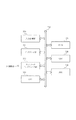
図1は本発明装置の構成を示すブロック図である。図中、1はコンピュータであり、CPU、メモリ、ハードディスク、CDROMドライブ、キーボード、マウス、モニタ、ネットワークインタフェース等のハードウェアを備える。図7は、コンピュータの構成を示すブロック図である。
[First Embodiment]
FIG. 1 is a block diagram showing the configuration of the apparatus of the present invention. In the figure, reference numeral 1 denotes a computer, which includes hardware such as a CPU, memory, hard disk, CD ROM drive, keyboard, mouse, monitor, and network interface. FIG. 7 is a block diagram illustrating the configuration of the computer.
図4において、コンピュータは、入力制御部700、ディスプレイ部701、ネットワークインタフェース部702、CPU703、ROM704、RAM705、HDD706、入出力インタフェース707を備えている。
4, the computer, the input control unit 7 00, the display unit 7 01, the network interface unit 7 02, CPU 7 03, ROM 7 04, RAM 7 05, HDD 7 06, and a input-
上記各部は入出力インタフェース707を介して接続されている。入力制御部700は、ユーザから入力を受け付けるキーボード/マウスを制御する。ディスプレイ部701は、ユーザに出力画面(モニタ)を提供する。ネットワークインタフェース部702は、ネットワーク101を介して外部機器と通信を行う。CPU703は、コンピュータ各部の制御を司るものであり、該コンピュータがサーバコンピュータ102の場合は、ROM704またはHDD706に格納された図3、5に示す制御プログラムに基づきコンピュータ側の処理を実行する。ROM704は、制御プログラム及びデータを格納している。RAM705は、一時記憶領域や作業領域として使用される。HDD706は、大容量の記憶領域を備えており、制御プログラム及び各種データを記憶する。
The above units are connected via the input-
2はオペレーティングシステムであり、コンピュータ1が備えるハードウェア、およびアプリケーション3、プリンタドライバ4、ランゲージモニタ5、ネットワークポートドライバ6などのソフトウェアを管理する。
アプリケーション3は、例えばワードプロセッサのようなアプリケーションソフトウェアであり、操作者の指示に従って文書の作成・印刷などを行う。
The
4はプリンタドライバであり、アプリケーション3が発行した印刷指令をオペレーティングシステム2を経て受け取り、該印刷指令をランゲージモニタ5、およびプリンタ7が解釈可能なプリンタコマンドに変換する。
A
5はランゲージモニタであり、プリンタドライバ4が出力したプリンタコマンドを受け取り、ネットワークポートドライバ6を経由してプリンタ7に送信する。ランゲージモニタ5はまた、プリンタ7からネットワークポートドライバ6を経由して受信した濃度補正情報、および色ずれ補正情報をプリンタドライバ4に通知する。
A
6はネットワークポートドライバである。ネットワークポートドライバ6は、ランゲージモニタ5が出力したプリンタコマンドをネットワークインタフェースを経てプリンタ7に送信するとともに、プリンタ7から濃度補正情報、および色ずれ補正情報を受信した場合にはランゲージモニタ5に出力する。
Reference numeral 6 denotes a network port driver. The network port driver 6 transmits the printer command output from the
7はプリンタであり、ネットワークポートドライバ6から受信したプリンタコマンドに従って印刷を行う。 A printer 7 prints according to the printer command received from the network port driver 6.
図2はプリンタ7の構成を示すブロック図である。図中、21はネットワークインタフェースであり、コンピュータ1からプリンタコマンドを受信する。22はFIFO(ファーストインファーストアウト)メモリであり、ネットワークインタフェース21から受信した画像データを色毎に格納する。復号回路23は、FIFOメモリ22に記憶された色毎の画像データを復号し、プリンタエンジン24に出力する。プリンタエンジン24は、レーザビームプリンタエンジンであり、制御回路25の指示により、復号回路23が出力した画像データに従って印刷を行う。25は制御回路であり、例えば1チップCPUで構成され、ネットワークインタフェース21、FIFOメモリ22、復号回路23およびプリンタエンジン24の制御を行う。
FIG. 2 is a block diagram showing the configuration of the printer 7. In the figure,
以下、印刷動作について説明する。 Hereinafter, the printing operation will be described.
操作者がコンピュータ1側でアプリケーション3を操作して印刷を指示すると、アプリケーション3からオペレーティングシステム2を経由してプリンタドライバ4に印刷指令が渡される。プリンタドライバ4はアプリケーション3から発行された印刷指令に基づき、画像データに変換して圧縮し、圧縮した画像データを、用紙サイズ、左余白、上余白、ビットマップデータのラインの長さとライン数などを指定するページ開始コマンド、ページの終了を示すページ終了コマンドとともに出力する。
When the operator operates the
プリンタコマンドが出力されると、オペレーティングシステム2はランゲージモニタ5にジョブ開始を通知した後に、出力されたプリンタコマンドを順次ランゲージモニタ5に引き渡す。ランゲージモニタ5は、ジョブが開始されると、占有要求コマンドをプリンタ7に送信する。
When the printer command is output, the
ランゲージモニタ5はプリンタの占有に成功すると、受け取ったプリンタコマンドを順次プリンタ7に送信する。なおランゲージモニタ5は画像データコマンドをプリンタ7に送信する前に、ステータス要求コマンドを送信し、プリンタ7のステータスを取得して、画像データコマンドが送信可能であることを確認する。制御回路25は、画像データコマンドを受信すると、画像データをFIFOメモリ22に格納する。ランゲージモニタ5は、1ページのプリンタコマンドを送信し終えると、印刷要求コマンドを送信する。制御回路25は、印刷要求コマンドを受信すると、プリンタエンジン24に対して印刷開始を指示する。
When the
プリンタエンジン24は印刷開始を指示されると、給紙を行い、用紙が所定の位置に達したときに画像データの出力を要求する。画像データの出力が要求されると、復号回路23はFIFOメモリ22から圧縮された画像を読み出し、復号した元の画像データをプリンタエンジン24に出力する。このときFIFOメモリ22から読み出された画像データは、FIFOメモリ22から取り除かれる。
When instructed to start printing, the printer engine 24 feeds paper and requests output of image data when the paper reaches a predetermined position. When the output of image data is requested, the
このようにしてジョブの全ページのプリンタコマンドを転送し終えると、ランゲージモニタ5は排紙完了を待たずに占有解除コマンドを送信する。ランゲージモニタ5はまた、占有解除コマンドを送信した後もプリンタ7のステータス取得を続け、取得したプリンタステータスがページの印刷が正常終了したことを示した場合には、該当するページメモリを解放するとともに、エラーを検出した場合には、再度占有要求コマンドを送信し、エラーページの回復を試みる。 When the printer commands for all the pages of the job have been transferred in this way, the language monitor 5 transmits an occupation release command without waiting for the completion of paper discharge. The language monitor 5 also continues to acquire the status of the printer 7 after sending the exclusive release command, and if the acquired printer status indicates that the page printing has been completed normally, the corresponding page memory is released. If an error is detected, an occupancy request command is transmitted again to try to recover the error page.
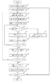
次に図3を参照し、ホストで動作するプリンタドライバ4の処理の詳細を説明する。なお、本フローの実行される前に、プリンタドライバは、印刷ジョブの開始毎にプリンタの不揮発メモリに記憶された各色の副走査方向の補正量情報をプリンタから取得する。まず、S1にて、アプリケーション3の指定に従い、用紙サイズ、左余白、上余白、ビットマップデータのラインの長さとライン数などを指定するページ開始コマンドを出力する。この際、後述するように、上余白およびビットマップデータのライン数に補正を加える。次にS11にて、後述する各主走査位置における副走査補正量をコマンドとして出力する。なお、このコマンドは印刷に必要なものではないが、後に副走査補正を取り消したり、別のエンジンの補正量にしたがって再補正を行う必要が生じた場合に参照される。
Next, details of processing of the
次にS2にて、アプリケーション3の描画指示に従い、赤、緑、青の各色8ビットからなる画像データを1バンド作成する。次にS3にて、赤、緑、青の各色8ビットからなる各画素を、イエロー、マゼンタ、シアン、黒の各色8ビットからなる画像データに変換する。この際、ジョブ開始時などにあらかじめ取得した濃度補正情報を参照して濃度補正を行う。次にS4にて、イエロー、マゼンタ、シアン、黒の各色8ビットからなる画像データにディザ処理を施し、イエロー、マゼンタ、シアン、黒の各色2ビットからなる画像データに変換する。次にS5にて、後述する色ずれ補正手順に従い、副走査方向の色ずれを補正する。この際に、後述するようにバンドバッファからはみ出る画像があるため、これを中間バッファに保持する。次にS6にて、1バンドの各色の画像データを圧縮し、出力する。次にS7にて、ページ内の全バンドの処理が終了したか判定する。ページ内の全バンドの処理が終了していない場合にはS2に戻り、次のバンドの処理を行う。
Next, in S2, one band of image data composed of 8 bits for each color of red, green, and blue is created according to the drawing instruction of the
S7にて、ページ内の全バンドの処理が終了している場合には、S8にて、中間バッファに保持したデータ、すなわち最後に処理したバンドからはみ出た画像データを圧縮し、出力する。次にS9にて、ページ終了コマンドを出力する。次にS10にて、全ページの処理が終了したか判定する。全ページの処理が終了していない場合にはS1に戻り、次のページの処理を行う。全ページの処理が終了している場合には、処理を終了する。 If the processing for all the bands in the page has been completed in S7, the data held in the intermediate buffer, that is, the image data protruding from the last processed band is compressed and output in S8. In step S9, a page end command is output. Next, in S10, it is determined whether or not all pages have been processed. If all the pages have not been processed, the process returns to S1 to process the next page. If all pages have been processed, the process ends.
次に、副走査方向の補正量の求め方を説明する。工場出荷前に、各色の副走査方向補正量を測定し、最大用紙の左端、中央、及び右端における各色の副走査方向補正量をプリンタの制御回路25内蔵の不揮発メモリにあらかじめ記録しておく。プリンタドライバ4は印刷ジョブの開始時にこの値をプリンタから取得し、まず2次関数で近似を行う。
Next, how to determine the correction amount in the sub-scanning direction will be described. Prior to factory shipment, the sub-scanning direction correction amount of each color is measured, and the sub-scanning direction correction amounts of each color at the left end, center, and right end of the maximum sheet are recorded in advance in a nonvolatile memory built in the
具体的には、最大用紙の左端、中央、及び右端における副走査方向補正量をそれぞれL、MおよびRとすると補正量Z=AX2+BX+Cは以下に示すように計算できる。ここでXは中央を原点とする主走査方向の位置であり、最大用紙の左端、中央、及び右端のX座標はそれぞれ−W/2、0、W/2となる。ここでWは最大用紙の用紙幅である。 Specifically, assuming that the sub-scanning direction correction amounts at the left end, center, and right end of the maximum sheet are L, M, and R, respectively, the correction amount Z = AX 2 + BX + C can be calculated as follows. Here, X is a position in the main scanning direction with the center as the origin, and the X coordinates of the left end, the center, and the right end of the maximum sheet are −W / 2, 0, and W / 2, respectively. Here, W is the sheet width of the maximum sheet.
R=A(W/2)2+B(W/2)+C
M=C
L=A(−W/2)2+B(−W/2)+C
であるのでこれを解くと以下の式が得られる。
R = A (W / 2) 2 + B (W / 2) + C
M = C
L = A (−W / 2) 2 + B (−W / 2) + C
So solving this gives the following equation:
A=2(R+L−2M)/W2
B=(R−L)/W
C=M
したがって副走査方向補正量Zは以下の式で計算できる。
A = 2 (R + L-2M) / W 2
B = (RL) / W
C = M
Therefore, the sub-scanning direction correction amount Z can be calculated by the following equation.
Z=2(R+L−2M)(X/W)2+(R−L)(X/W)+M
次にこの式に基づき、副走査方向補正量を主走査方向の全ての画素位置について計算する。このとき、副走査方向の補正は1ライン単位で行うので、ライン単位の整数になるように四捨五入する。
Z = 2 (R + L-2M) (X / W) 2 + (R−L) (X / W) + M
Next, based on this equation, the sub-scanning direction correction amount is calculated for all pixel positions in the main scanning direction. At this time, since correction in the sub-scanning direction is performed in units of one line, rounding is performed so as to be an integer in line units.
次に図4を参照し、バンドバッファ上の座標から、上記副走査方向補正量を求める方法を説明する。用紙サイズが最大より小さい場合、用紙は中央に配置されるのが一般的である。したがって、補正を行う際に、用紙の配置を考慮して補正を行う必要がある。図4中、上部の水平線は上記X軸を示し、中央が原点となっている。また破線矩形は用紙を示し、その幅はwであり、用紙の中央がX座標原点と一致する。また実線矩形は、プリンタドライバ4が、図3のS2にて画像を作成する領域を示し、そのx座標およびy座標の原点は左上隅であり、またx座標原点は用紙左端から左余白LMだけ離れた位置にある。したがって、図に示すように、X座標原点はx座標ではw/2−LMとなるため、X座標は以下の式で計算される。
X=x+LM−w/2
こうして求められたX座標の値を用いて、前述の式により副走査補正量Zをx座標から求めることができる。
Next, referring to FIG. 4, a method for obtaining the correction amount in the sub-scanning direction from the coordinates on the band buffer will be described. When the paper size is smaller than the maximum, the paper is generally placed in the center. Therefore, when performing correction, it is necessary to perform correction in consideration of the layout of the paper. In FIG. 4, the upper horizontal line indicates the X axis, and the center is the origin. A broken-line rectangle indicates a sheet, its width is w, and the center of the sheet coincides with the X coordinate origin. A solid line rectangle indicates an area in which the
X = x + LM-w / 2
Using the value of the X coordinate thus obtained, the sub-scanning correction amount Z can be obtained from the x coordinate by the above formula.
なお、用紙サイズによって用紙幅wが異なるため、同一のxに対して異なったXが対応するので、同一のxに対して補正量は用紙サイズに応じて変化する。 Since the paper width w varies depending on the paper size, different Xs correspond to the same x, and therefore the correction amount for the same x varies depending on the paper size.
次に図5を参照し、図3のS5の色ずれ補正処理の詳細を説明する。本実施例では、1画素が各色2ビットにより構成され、1バイトに特定の色の画素が4つ含まれる。このため、1画素ごとに補正量を変化させると2ビット単位で処理を行う必要があり、処理時間が増大する。この問題を避けるために、1バイトに含まれる4画素に同一の補正量を適用することにより、1バイト単位で処理を行うことが可能となり、処理時間を短縮できる。 Next, the details of the color misregistration correction process in S5 of FIG. 3 will be described with reference to FIG. In this embodiment, one pixel is composed of 2 bits for each color, and one byte includes four pixels of a specific color. For this reason, if the correction amount is changed for each pixel, it is necessary to perform processing in units of 2 bits, which increases processing time. In order to avoid this problem, by applying the same correction amount to the four pixels included in one byte, it becomes possible to perform processing in units of one byte, and the processing time can be shortened.
まずS21にて、現在の色を最初の色、例えばシアンに設定する。次に現在の列を、現在の色のバンドバッファの先頭、すなわち左端に設定する。ここで列とは、幅1バイトからなるものとする。次にS23にて、現在の列の左端の画素の補正量を、前述のように計算する。この際、ジョブ開始時などにあらかじめ取得した色ずれ補正情報を参照して補正量を計算する。なお本実施例では、1画素が各色2ビットにより構成されるため、1バイトに特定の色の画素が4つ含まれるが、前述のようにバイト単位で処理を行うために、1バイト内の左端の画素の補正量をバイト内の4画素に適用する。次にS24にて、補正値に最大補正量を加算して、正または0の値になるようにする。例えば、補正量が−20ライン以上20ライン以下である場合、最大補正量である20ラインを加算して、0ライン以上40ライン以下となるようにする。この処理の目的は、補正量が負になった場合、現在のバンドのデータを補正した結果、すでに処理を終えている、前のバンドの位置にデータが移動することになり、処理が不可能になるのでそれを回避するためである。 First, in S21, the current color is set to the first color, for example, cyan. Next, the current column is set to the top, that is, the left end of the current color band buffer. Here, the column is assumed to have a width of 1 byte. Next, in S23, the correction amount of the leftmost pixel in the current column is calculated as described above. At this time, the correction amount is calculated with reference to color misregistration correction information acquired in advance at the start of the job. In this embodiment, since one pixel is composed of 2 bits for each color, one byte includes four pixels of a specific color. However, in order to perform processing in units of bytes as described above, The correction amount of the leftmost pixel is applied to the four pixels in the byte. Next, in S24, the maximum correction amount is added to the correction value so as to have a positive or zero value. For example, when the correction amount is -20 lines or more and 20 lines or less, the maximum correction amount of 20 lines is added to be 0 lines or more and 40 lines or less. The purpose of this process is that if the correction amount becomes negative, the data of the current band is corrected, and as a result, the data is moved to the position of the previous band that has already been processed. This is to avoid it.
次にS25にて、現在のバイトを現在の列の末尾、すなわちバンドバッファの最終ラインの現在の列に設定する。次にS26にて、現在のバイトの補正位置を計算し、補正位置がバンドバッファ内であるか判定する。具体的には、現在のバイトの、S24にて計算された補正ライン数下の位置が、バンドバッファ内であるか判定する。現在のバイトの補正位置がバンドバッファ内である場合には、S27にて現在のバイトを、S26で計算された補正位置にコピーし、S28に進む。現在のバイトの補正位置がバンドバッファ内でない場合には、中間バッファ2に、バンドバッファからはみ出るライン数に応じた位置にコピーし、S28に進む。
Next, in S25, the current byte is set to the end of the current column, that is, the current column of the last line of the band buffer. In step S26, the current byte correction position is calculated, and it is determined whether the correction position is within the band buffer. Specifically, it is determined whether the position below the number of correction lines calculated in S24 of the current byte is in the band buffer. If the correction position of the current byte is in the band buffer, the current byte is copied to the correction position calculated in S26 in S27, and the process proceeds to S28. If the correction position of the current byte is not within the band buffer, it is copied to the
S28では、現在のバイト位置を1つ上のラインに移動する。次にS29にて、1列の処理が終了したか、すなわち現在のバイト位置がバンドバッファの先頭からはみ出たか判定する。1列の処理が終了していない場合はS26に戻り、現在の列の処理を継続する。1列の処理が終了した場合は、S30にて、現在の列の、先頭ラインからS24にて計算された補正ライン数だけ、中間バッファ1からバンドバッファにコピーする。なお、中間バッファ1は、あらかじめ空白画素で埋められているものとする。次にS31にて、現在の列を右に1バイト移動する。次にS32にて、全ての列の処理が終了したか判定する。全ての列の処理が終了していない場合には、S23に戻り、次の列の処理を開始する。 In S28, the current byte position is moved up one line. Next, in S29, it is determined whether the processing for one column is completed, that is, whether the current byte position protrudes from the head of the band buffer. If the processing for one column is not completed, the process returns to S26 and the processing for the current column is continued. When the processing for one column is completed, in S30, the number of correction lines calculated in S24 from the first line in the current column is copied from the intermediate buffer 1 to the band buffer. It is assumed that the intermediate buffer 1 is previously filled with blank pixels. Next, in S31, the current column is moved to the right by 1 byte. Next, in S32, it is determined whether or not the processing for all the columns has been completed. If all the columns have not been processed, the process returns to S23 to start the next column.
全ての列の処理が終了した場合には、S33にて、中間バッファ2の内容を、現在の色の中間バッファ1にコピーする。次に、S34にて、現在の色を次の色に設定する。次にS35にて、全ての色の処理が終了したか判定する。全ての色の処理が終了していない場合は、S22に戻り、次の色の処理を開始する。全ての色の処理が終了している場合には、色ずれ補正処理を終了する。
なお、図3に示すS1にて行う上余白のライン数の補正は、S24にて補正量に加算する値、すなわち最大補正量を減算することにより行う。この処理を行うことによりS24にて補正量に加算することによる上余白の増加をキャンセルすることができる。また図3に示すS1にて行うビットマップデータのライン数の補正は、中間バッファのライン数を加算することにより行う。中間バッファのライン数は、最大補正量の2倍となっているので、その値を加算する。
If all the columns have been processed, the contents of the
The correction of the number of upper margin lines performed in S1 shown in FIG. 3 is performed by subtracting the value to be added to the correction amount, that is, the maximum correction amount in S24. By performing this process, it is possible to cancel the increase in the upper margin due to the addition to the correction amount in S24. Further, the correction of the number of lines of the bitmap data performed in S1 shown in FIG. 3 is performed by adding the number of lines of the intermediate buffer. Since the number of lines in the intermediate buffer is twice the maximum correction amount, the value is added.
なお、図5の処理を、たとえば図6のような横長のバンド(横方向:主走査方向)の例で説明する。まず、バンドの左下のバイト単位の画像データを補正量に応じてバンドバッファまたは中間バッファに書き込む。次に一つ上(縦方向(副走査方向))のバイト単位の画像データを補正量に応じてバンドバッファまたは中間バッファ書き込む。一つ上のバイト単位の画像データを順次処理していき、縦方向のバンド分の画像データの処理が終了したら、左下のバイト単位の画像データの右隣のバイト単位の画像データを補正量に応じてバンドバッファまたは中間バッファ書き込む。そして、次にその一つ上のバイト単位の画像データを順次処理していく。 The process of FIG. 5 will be described using an example of a horizontally long band (horizontal direction: main scanning direction) as shown in FIG. 6, for example. First, the image data in byte units at the lower left of the band is written into the band buffer or the intermediate buffer according to the correction amount. Next, the image data in byte units one level higher (vertical direction (sub-scanning direction)) is written into a band buffer or an intermediate buffer according to the correction amount. When the image data for the upper byte is sequentially processed and the processing of the image data for the vertical band is completed, the image data for the right byte of the image data for the lower left byte is used as the correction amount. Write band buffer or intermediate buffer accordingly. Then, the image data in byte units one level higher is sequentially processed.
上記例では縦方向(副走査方向)に処理する例を説明したが、横方向(主走査方向)に処理する方式でも実現できる。具体的には、バンドの左下のバイト単位の画像データを補正量に応じてバンドバッファまたは中間バッファに書き込む。次に一つ右(横方向:主走査方向)のバイト単位の画像データを補正量に応じてバンドバッファまたは中間バッファ書き込む。一つ右のバイト単位の画像データを順次処理していき、横方向にバンド分の画像データの処理が終了したら、左下のバイト単位の画像データの一つ上のバイト単位の画像データを補正量に応じてバンドバッファまたは中間バッファ書き込む。そして、一つ右のバイト単位の画像データを順次処理していく方式を採用してもよい。 In the above example, an example of processing in the vertical direction (sub-scanning direction) has been described, but a method of processing in the horizontal direction (main scanning direction) can also be realized. Specifically, the image data in byte units at the lower left of the band is written in the band buffer or the intermediate buffer according to the correction amount. Next, image data in byte units one right (horizontal direction: main scanning direction) is written into a band buffer or an intermediate buffer according to the correction amount. When the image data for the right byte is processed sequentially, and the processing of the image data for the band in the horizontal direction is completed, the image data for the byte one byte above the image data for the lower left byte is corrected. Depending on the band buffer or intermediate buffer write. A method of sequentially processing the image data in the right byte unit may be adopted.
次に図6を参照し、色ずれ補正処理によるデータの動きを説明する。まず最初のバンドであるバンド1の画像データ601がバンドバッファに形成され、色ずれ補正処理が呼び出されると、副走査方向補正量に応じて補正が行われ、バンドバッファ内にとどまるデータ602と、はみ出て中間バッファ2に格納されるデータ603に分かれる。中間バッファ2に格納されたデータ603は、1バンド処理終了時点で中間バッファ1に画像データ604としてコピーされている。次にバンド2の画像データ605がバンドバッファに形成され、色ずれ補正処理が呼び出されると、同様にバンドバッファ内にとどまるデータ606と、はみ出て中間バッファ2に格納されるデータ607に分かれ、さらに中間バッファ1に保持されていた、バンド1からはみ出たデータ604がバンドバッファに格納される。
Next, with reference to FIG. 6, the data movement by the color misregistration correction process will be described. First, image data 601 of band 1, which is the first band, is formed in the band buffer, and when color misregistration correction processing is called up, correction is performed according to the sub-scanning direction correction amount, and data 602 staying in the band buffer; The data 603 is separated into data 603 stored in the
このようにして順次補正処理が行われ、最後のバンドの処理後には、最後のバンドからはみ出たデータ610が中間バッファ1に保持されている。このデータ610は、図3に示すS8の処理により出力される。 In this way, the correction processing is sequentially performed, and after the processing of the last band, the data 610 protruding from the last band is held in the intermediate buffer 1. This data 610 is output by the process of S8 shown in FIG.
〔第2実施形態〕
次に、本発明方式の第2の実施形態を説明する。本実施形態においては、ディザ処理の前に色ずれ補正処理を行う。具体的には、図3に示すS4のディザ処理と、S5の色ずれ処理の順序を入れ替える。また、ディザ処理前の画像は各色8ビットであるため、色ずれ補正処理に際して、4画素に同一補正量を適用することなく、各画素ごとに補正量が計算される。
[Second Embodiment]
Next, a second embodiment of the method of the present invention will be described. In the present embodiment, color misregistration correction processing is performed before dither processing. Specifically, the order of the dither process in S4 and the color misregistration process in S5 shown in FIG. Further, since the image before dither processing is 8 bits for each color, the correction amount is calculated for each pixel without applying the same correction amount to the four pixels in the color misregistration correction processing.
〔第3実施形態〕
次に、本発明方式の第3の実施形態を説明する。本実施形態においては、プリンタエンジン24は両面印刷機構を有する。両面印刷の場合、第1面の印刷は片面印刷と同様に中央基準が一般的であるが、第2面の印刷に際しては、左基準となっている場合がある。このような場合、図5に示すS23にて計算する補正量は、両面印刷第1面の場合には第1の実施形態と同様に中央基準で計算し、両面印刷第2面の場合には左基準で計算する。具体的には前述の
X=x+LM−w/2
のかわりに、用紙幅にかかわらず最大用紙と同じ式、すなわち
X=x+LM−W/2
により計算を行えばよい。
[Third Embodiment]
Next, a third embodiment of the method of the present invention will be described. In the present embodiment, the printer engine 24 has a duplex printing mechanism. In the case of double-sided printing, the center reference is generally the same as the first side printing as in the case of single-sided printing, but the second side printing may be the left reference. In such a case, the correction amount calculated in S23 shown in FIG. 5 is calculated on the basis of the center in the case of the first side of double-sided printing as in the first embodiment, and in the case of the second side of double-sided printing. Calculate with the left reference. Specifically, the above mentioned X = x + LM−w / 2
Instead of the same formula as the largest sheet, regardless of the sheet width, ie X = x + LM−W / 2
The calculation may be performed by the following.
なお両面印刷を行う場合、用紙の搬送方向(縦送りまたは横送り)および綴じ方向(長辺とじまたは短辺とじ)の組み合わせによっては、第1面の画像を180度回転する必要があるが、この処理は図3に示すS2にて画像を作成する際にあらかじめ回転した画像を作成するものとする。 When performing double-sided printing, it is necessary to rotate the image on the first side by 180 degrees depending on the combination of the paper transport direction (vertical feed or horizontal feed) and the binding direction (long side binding or short side binding) In this process, it is assumed that an image rotated in advance is created when the image is created in S2 shown in FIG.
〔その他の実施形態〕
なお、上述の実施例では、画像作成および色ずれ補正をホストコンピュータで行っているが、これに代えて他の手段、例えばプリンタドライバ4は画像作成および色ずれ補正を行わずにページ記述言語を出力し、プリンタ7は受信したページ記述言語にしたがって画像の作成および色ずれ補正を行うようにしてもよい。
[Other Embodiments]
In the above-described embodiment, image creation and color misregistration correction are performed by the host computer. Instead, other means, for example, the
1 コンピュータ
2 オペレーティングシステム
3 アプリケーション
4 プリンタドライバ
5 ランゲージモニタ
6 ネットワークポートドライバ
7 プリンタ
21 ネットワークインタフェース
22 FIFOメモリ
23 復号回路
24 プリンタエンジン
25 制御回路
1
Claims (15)
前記バンドバッファに格納された画像を用紙の複数位置における副走査方向の補正量に基づき補正する画像補正手段と、
前記画像補正手段により補正されたバンド領域からはみ出る画像を格納する第1の中間バッファと、
前記第1の中間バッファに格納された前記画像補正手段により補正されたバンド領域からはみ出る画像を第2の中間バッファにコピーし、次のバンドの画像を前記バンドバッファに格納し、前記画像補正手段により前記バンドバッファに格納された次のバンドの画像を用紙の複数位置における副走査方向の補正量に基づき補正し、次のバンドの前記画像補正手段により補正されたバンド領域からはみ出ない画像が格納されているバンドバッファに前記第2の中間バッファに格納された前のバンドのバンド領域からはみ出た部分の画像を格納し、前記バンドバッファに格納された次のバンドの前記画像補正手段により補正されたバンド領域からはみ出ない画像と前のバンドのバンド領域からはみ出た部分の画像を含む画像を出力する画像出力手段とを有することを特徴とする印刷制御装置。 A band buffer for storing an image of one band;
Image correction means for correcting the image stored in the band buffer based on correction amounts in the sub-scanning direction at a plurality of positions on the paper;
A first intermediate buffer for storing an image protruding from the band region corrected by the image correction means;
The image that protrudes from the band area corrected by the image correction means stored in the first intermediate buffer is copied to a second intermediate buffer, the image of the next band is stored in the band buffer, and the image correction means The image of the next band stored in the band buffer is corrected based on the correction amount in the sub-scanning direction at a plurality of positions on the sheet, and an image that does not protrude from the band area corrected by the image correction unit of the next band is stored. The image of the portion of the previous band that is stored in the second intermediate buffer is stored in the band buffer that is stored in the second buffer, and is corrected by the image correction unit for the next band stored in the band buffer. image output hands for outputting an image including an image of a run-off portions from the image and the band area in front of the band does not protrude from the band area Print control apparatus characterized by having and.
前記バンドバッファに格納された画像を用紙の複数位置における副走査方向の補正量に基づき補正する画像補正ステップと、
前記画像補正ステップにより補正されたバンド領域からはみ出る画像を第1の中間バッファに格納する第2格納ステップと、
前記第1の中間バッファに格納された前記画像補正ステップにより補正されたバンド領域からはみ出る画像を第2の中間バッファにコピーし、次のバンドの画像を前記バンドバッファに格納し、前記画像補正ステップにより前記バンドバッファに格納された次のバンドの画像を用紙の複数位置における副走査方向の補正量に基づき補正し、次のバンドの前記画像補正ステップにより補正されたバンド領域からはみ出ない画像が格納されているバンドバッファに前記第2の中間バッファに格納された前のバンドのバンド領域からはみ出た部分の画像を格納し、前記バンドバッファに格納された次のバンドの前記画像補正ステップにより補正されたバンド領域からはみ出ない画像と前のバンドのバンド領域からはみ出た部分の画像を含む画像を出力する画像出力ステップとを有することを特徴とする印刷制御方法。 A first storing step of storing an image of one band in a band buffer;
An image correction step of correcting the image stored in the band buffer based on the correction amount in the sub-scanning direction at a plurality of positions on the paper;
A second storage step of storing in the first intermediate buffer the image protruding from the band region corrected by the image correction step;
The image that protrudes from the band region corrected by the image correction step stored in the first intermediate buffer is copied to a second intermediate buffer, the image of the next band is stored in the band buffer, and the image correction step The image of the next band stored in the band buffer is corrected based on the correction amount in the sub-scanning direction at a plurality of positions on the sheet, and an image that does not protrude from the band area corrected by the image correction step of the next band is stored. The image of the part of the previous band stored in the second intermediate buffer is stored in the band buffer being stored, and is corrected by the image correction step for the next band stored in the band buffer. out of the image, including the image of the run-off portions from the image and the band area in front of the band that does not protrude from the band region Printing control method characterized by and an image output step of.
Priority Applications (4)
| Application Number | Priority Date | Filing Date | Title |
|---|---|---|---|
| JP2005314706A JP4617240B2 (en) | 2005-10-28 | 2005-10-28 | PRINT CONTROL DEVICE, PRINT CONTROL METHOD, PROGRAM, AND STORAGE MEDIUM |
| US11/549,526 US7903304B2 (en) | 2005-10-28 | 2006-10-13 | Print control apparatus, print control method, program, and storage medium |
| CN200610142963.0A CN100586146C (en) | 2005-10-28 | 2006-10-27 | Print control apparatus and print control method |
| US13/018,753 US8873118B2 (en) | 2005-10-28 | 2011-02-01 | Print control apparatus, print control method, program, and storage medium correcting images in band buffer based on amount of correction |
Applications Claiming Priority (1)
| Application Number | Priority Date | Filing Date | Title |
|---|---|---|---|
| JP2005314706A JP4617240B2 (en) | 2005-10-28 | 2005-10-28 | PRINT CONTROL DEVICE, PRINT CONTROL METHOD, PROGRAM, AND STORAGE MEDIUM |
Publications (3)
| Publication Number | Publication Date |
|---|---|
| JP2007122478A JP2007122478A (en) | 2007-05-17 |
| JP2007122478A5 JP2007122478A5 (en) | 2007-12-27 |
| JP4617240B2 true JP4617240B2 (en) | 2011-01-19 |
Family
ID=37995898
Family Applications (1)
| Application Number | Title | Priority Date | Filing Date |
|---|---|---|---|
| JP2005314706A Expired - Fee Related JP4617240B2 (en) | 2005-10-28 | 2005-10-28 | PRINT CONTROL DEVICE, PRINT CONTROL METHOD, PROGRAM, AND STORAGE MEDIUM |
Country Status (3)
| Country | Link |
|---|---|
| US (2) | US7903304B2 (en) |
| JP (1) | JP4617240B2 (en) |
| CN (1) | CN100586146C (en) |
Families Citing this family (6)
| Publication number | Priority date | Publication date | Assignee | Title |
|---|---|---|---|---|
| JP2008259070A (en) * | 2007-04-06 | 2008-10-23 | Canon Inc | Image forming device, control method thereof, program, and storage medium |
| US7889404B2 (en) * | 2007-05-31 | 2011-02-15 | Ricoh Company, Ltd. | Image reading device, image forming apparatus, and reading-unit install method |
| JP5219647B2 (en) * | 2008-06-24 | 2013-06-26 | キヤノン株式会社 | Image forming apparatus, image forming system, and image processing method |
| JP4968550B2 (en) * | 2009-08-31 | 2012-07-04 | ブラザー工業株式会社 | Printing device |
| JP5517569B2 (en) * | 2009-11-13 | 2014-06-11 | キヤノン株式会社 | Image processing apparatus and image processing method |
| US20130258377A1 (en) * | 2010-03-31 | 2013-10-03 | Canon Kabushiki Kaisha | Printer control system, printing method, and storage medium |
Citations (3)
| Publication number | Priority date | Publication date | Assignee | Title |
|---|---|---|---|---|
| JPH07256933A (en) * | 1994-03-24 | 1995-10-09 | Fuji Xerox Co Ltd | Image recorder |
| JP2004268569A (en) * | 2002-10-29 | 2004-09-30 | Konica Minolta Holdings Inc | Image formation device and its main scanning deviation correction method and main scanning deviation correction method thereof |
| JP2004345325A (en) * | 2003-05-26 | 2004-12-09 | Konica Minolta Business Technologies Inc | Management system for image forming apparatus |
Family Cites Families (9)
| Publication number | Priority date | Publication date | Assignee | Title |
|---|---|---|---|---|
| DE69712609T2 (en) * | 1996-02-23 | 2003-01-30 | Copyer Co | IMAGING DEVICE |
| JPH10243248A (en) | 1997-02-28 | 1998-09-11 | Canon Inc | Electronic device, image-processing unit and control method therefor |
| US6021258A (en) * | 1996-06-27 | 2000-02-01 | Canon Kabushiki Kaisha | Electronic apparatus, image process apparatus, image process method and storage medium |
| US6029041A (en) * | 1997-11-21 | 2000-02-22 | Minolta Co., Ltd. | Image forming apparatus |
| TW399186B (en) * | 1997-12-10 | 2000-07-21 | Canon Kk | Image processing apparatus and image processing method |
| JP3711430B2 (en) * | 1998-03-27 | 2005-11-02 | セイコーエプソン株式会社 | Tape printing apparatus and method for creating printed image for tape |
| JP2001038964A (en) | 1999-07-29 | 2001-02-13 | Matsushita Electric Ind Co Ltd | Printer controller |
| US6624901B1 (en) * | 2000-04-18 | 2003-09-23 | Kba (Advanced Imaging Technology) Limited | Digital skew correction method and apparatus for multi color printing machine |
| US7471411B2 (en) * | 2002-10-29 | 2008-12-30 | Konica Minolta Holdings Inc. | Image printing apparatus and method of adjusting and correcting main-scanning offset in image printing apparatus |
-
2005
- 2005-10-28 JP JP2005314706A patent/JP4617240B2/en not_active Expired - Fee Related
-
2006
- 2006-10-13 US US11/549,526 patent/US7903304B2/en not_active Expired - Fee Related
- 2006-10-27 CN CN200610142963.0A patent/CN100586146C/en not_active Expired - Fee Related
-
2011
- 2011-02-01 US US13/018,753 patent/US8873118B2/en not_active Expired - Fee Related
Patent Citations (3)
| Publication number | Priority date | Publication date | Assignee | Title |
|---|---|---|---|---|
| JPH07256933A (en) * | 1994-03-24 | 1995-10-09 | Fuji Xerox Co Ltd | Image recorder |
| JP2004268569A (en) * | 2002-10-29 | 2004-09-30 | Konica Minolta Holdings Inc | Image formation device and its main scanning deviation correction method and main scanning deviation correction method thereof |
| JP2004345325A (en) * | 2003-05-26 | 2004-12-09 | Konica Minolta Business Technologies Inc | Management system for image forming apparatus |
Also Published As
| Publication number | Publication date |
|---|---|
| US8873118B2 (en) | 2014-10-28 |
| US20070097466A1 (en) | 2007-05-03 |
| CN1960432A (en) | 2007-05-09 |
| US7903304B2 (en) | 2011-03-08 |
| CN100586146C (en) | 2010-01-27 |
| JP2007122478A (en) | 2007-05-17 |
| US20110122447A1 (en) | 2011-05-26 |
Similar Documents
| Publication | Publication Date | Title |
|---|---|---|
| US8842325B2 (en) | Image processing apparatus, control method thereof, and storage medium | |
| JP4617240B2 (en) | PRINT CONTROL DEVICE, PRINT CONTROL METHOD, PROGRAM, AND STORAGE MEDIUM | |
| US8508775B2 (en) | Image processing with body region image and peripheral region image | |
| US20100103435A1 (en) | Image processing apparatus and image processing method for processing screen-processed image | |
| JP5339824B2 (en) | Image forming apparatus and control method thereof | |
| US8441690B2 (en) | Image processing apparatus and image processing method for processing screen-processed image | |
| JP4491027B2 (en) | Image forming apparatus, image processing method, program, and storage medium | |
| JP2012232590A (en) | System and program for forming image | |
| US6226095B1 (en) | Image processing apparatus, method, and system | |
| JP4891273B2 (en) | Image forming apparatus and control method thereof | |
| JP4942205B2 (en) | Image forming apparatus, image forming apparatus control method, and program | |
| JP4560570B2 (en) | Information processing apparatus, information processing method, and print control program | |
| JP4404016B2 (en) | Driver program | |
| JP3858956B2 (en) | PRINT CONTROL METHOD, PRINT CONTROL DEVICE, MEDIUM RECORDING PRINT CONTROL PROGRAM, AND PRINTING DEVICE | |
| US20120121201A1 (en) | Image processing apparatus and image processing method | |
| JP2020108107A (en) | Image processing device, control method, and program | |
| JP4222303B2 (en) | Image forming apparatus | |
| JP2006159468A (en) | Printing device and printing method | |
| JPH11196246A (en) | Image forming device | |
| US20110063679A1 (en) | Image processing apparatus | |
| JP2006101285A (en) | Image processor | |
| JP2006164066A (en) | Data processing system, data processor, data processing method and control program | |
| JP2004023164A (en) | Image coding device, image coding method, program, and storage medium | |
| JP2006171976A (en) | Print processing method |
Legal Events
| Date | Code | Title | Description |
|---|---|---|---|
| A521 | Request for written amendment filed |
Free format text: JAPANESE INTERMEDIATE CODE: A523 Effective date: 20071113 |
|
| A621 | Written request for application examination |
Free format text: JAPANESE INTERMEDIATE CODE: A621 Effective date: 20071113 |
|
| A977 | Report on retrieval |
Free format text: JAPANESE INTERMEDIATE CODE: A971007 Effective date: 20091224 |
|
| A131 | Notification of reasons for refusal |
Free format text: JAPANESE INTERMEDIATE CODE: A131 Effective date: 20100105 |
|
| RD04 | Notification of resignation of power of attorney |
Free format text: JAPANESE INTERMEDIATE CODE: A7424 Effective date: 20100201 |
|
| A521 | Request for written amendment filed |
Free format text: JAPANESE INTERMEDIATE CODE: A523 Effective date: 20100304 |
|
| A02 | Decision of refusal |
Free format text: JAPANESE INTERMEDIATE CODE: A02 Effective date: 20100518 |
|
| RD01 | Notification of change of attorney |
Free format text: JAPANESE INTERMEDIATE CODE: A7421 Effective date: 20100630 |
|
| A521 | Request for written amendment filed |
Free format text: JAPANESE INTERMEDIATE CODE: A523 Effective date: 20100818 |
|
| A911 | Transfer to examiner for re-examination before appeal (zenchi) |
Free format text: JAPANESE INTERMEDIATE CODE: A911 Effective date: 20100827 |
|
| TRDD | Decision of grant or rejection written | ||
| A01 | Written decision to grant a patent or to grant a registration (utility model) |
Free format text: JAPANESE INTERMEDIATE CODE: A01 Effective date: 20101019 |
|
| A01 | Written decision to grant a patent or to grant a registration (utility model) |
Free format text: JAPANESE INTERMEDIATE CODE: A01 |
|
| A61 | First payment of annual fees (during grant procedure) |
Free format text: JAPANESE INTERMEDIATE CODE: A61 Effective date: 20101025 |
|
| R150 | Certificate of patent or registration of utility model |
Ref document number: 4617240 Country of ref document: JP Free format text: JAPANESE INTERMEDIATE CODE: R150 Free format text: JAPANESE INTERMEDIATE CODE: R150 |
|
| FPAY | Renewal fee payment (event date is renewal date of database) |
Free format text: PAYMENT UNTIL: 20131029 Year of fee payment: 3 |
|
| LAPS | Cancellation because of no payment of annual fees |