JP4615975B2 - Scroll type fluid machine - Google Patents
Scroll type fluid machine Download PDFInfo
- Publication number
- JP4615975B2 JP4615975B2 JP2004346747A JP2004346747A JP4615975B2 JP 4615975 B2 JP4615975 B2 JP 4615975B2 JP 2004346747 A JP2004346747 A JP 2004346747A JP 2004346747 A JP2004346747 A JP 2004346747A JP 4615975 B2 JP4615975 B2 JP 4615975B2
- Authority
- JP
- Japan
- Prior art keywords
- scroll
- casing
- cooling
- cooling air
- fan
- Prior art date
- Legal status (The legal status is an assumption and is not a legal conclusion. Google has not performed a legal analysis and makes no representation as to the accuracy of the status listed.)
- Expired - Fee Related
Links
Images


Classifications
-
- F—MECHANICAL ENGINEERING; LIGHTING; HEATING; WEAPONS; BLASTING
- F04—POSITIVE - DISPLACEMENT MACHINES FOR LIQUIDS; PUMPS FOR LIQUIDS OR ELASTIC FLUIDS
- F04C—ROTARY-PISTON, OR OSCILLATING-PISTON, POSITIVE-DISPLACEMENT MACHINES FOR LIQUIDS; ROTARY-PISTON, OR OSCILLATING-PISTON, POSITIVE-DISPLACEMENT PUMPS
- F04C18/00—Rotary-piston pumps specially adapted for elastic fluids
- F04C18/02—Rotary-piston pumps specially adapted for elastic fluids of arcuate-engagement type, i.e. with circular translatory movement of co-operating members, each member having the same number of teeth or tooth-equivalents
- F04C18/0207—Rotary-piston pumps specially adapted for elastic fluids of arcuate-engagement type, i.e. with circular translatory movement of co-operating members, each member having the same number of teeth or tooth-equivalents both members having co-operating elements in spiral form
- F04C18/0215—Rotary-piston pumps specially adapted for elastic fluids of arcuate-engagement type, i.e. with circular translatory movement of co-operating members, each member having the same number of teeth or tooth-equivalents both members having co-operating elements in spiral form where only one member is moving
Landscapes
- Engineering & Computer Science (AREA)
- Mechanical Engineering (AREA)
- General Engineering & Computer Science (AREA)
- Applications Or Details Of Rotary Compressors (AREA)
- Rotary Pumps (AREA)
Description
本発明は、例えば空気、冷媒等の圧縮機や真空ポンプ等に用いて好適なスクロール式流体機械に関する。 The present invention relates to a scroll fluid machine suitable for use in a compressor such as air or refrigerant, a vacuum pump, or the like.
一般に、スクロール式流体機械としては、回転軸の軸方向両側に旋回スクロールをそれぞれ設け、この回転軸を駆動することによって両側の2箇所で空気等の圧縮動作を行う構成としたスクロール式空気圧縮機が知られている(例えば、特許文献1参照)。 Generally, as a scroll type fluid machine, a scroll type air compressor having a configuration in which orbiting scrolls are provided on both sides in the axial direction of a rotary shaft and the rotary shaft is driven to compress air or the like at two locations on both sides. Is known (see, for example, Patent Document 1).
この種の従来技術による空気圧縮機は、筒状をなすケーシングの軸方向両側に第1,第2の固定スクロールが設けられ、これらの固定スクロールは、鏡板の表面に渦巻状のラップ部がそれぞれ立設されている。 This type of prior art air compressor is provided with first and second fixed scrolls on both axial sides of a cylindrical casing, and these fixed scrolls have spiral wrap portions on the surface of the end plate, respectively. It is erected.
また、ケーシング内には、筒状のロッドからなる回転軸と、この回転軸を回転駆動する電動機とが設けられている。そして、回転軸の内周側には、その中心軸線に対して一定の寸法だけ偏心した連結軸が回転可能に挿通され、この連結軸の両端は、回転軸の軸方向両側から突出して、回転軸に対し偏心したクランク部となっている。 Further, a rotating shaft composed of a cylindrical rod and an electric motor that rotationally drives the rotating shaft are provided in the casing. Then, on the inner peripheral side of the rotating shaft, a connecting shaft eccentric by a fixed dimension with respect to the central axis is rotatably inserted, and both ends of the connecting shaft protrude from both axial sides of the rotating shaft and rotate. The crank part is eccentric with respect to the shaft.
また、これらのクランク部には、鏡板の表面に渦巻状のラップ部が立設された第1,第2の旋回スクロールがそれぞれ連結され、該各旋回スクロールのラップ部は、第1,第2の固定スクロールのラップ部とそれぞれ重なり合うことにより、複数の圧縮室を画成している。 These crank portions are connected to first and second orbiting scrolls each having a spiral lap portion standing on the surface of the end plate, and the wrap portions of the orbiting scrolls are respectively connected to the first and second orbiting scrolls. A plurality of compression chambers are defined by overlapping with the wrap portions of the fixed scroll.
この場合、各旋回スクロールの鏡板は、その内部に冷却風の通路と冷却フィンとが設けられた2層構造の板状体として形成され、さらに鏡板の裏面側には、連結軸に取付けられる金属板等が設けられている。 In this case, the end plate of each orbiting scroll is formed as a two-layered plate-like body in which a cooling air passage and a cooling fin are provided, and on the back side of the end plate, a metal attached to the connecting shaft is formed. A plate or the like is provided.
そして、空気圧縮機の運転時には、電動機により回転軸が回転駆動されると、その両端側に連結された第1,第2の旋回スクロールが各固定スクロールに対して旋回運動し、第1の固定スクロールと旋回スクロールとの間、及び第2の固定スクロールと旋回スクロールとの間で空気の圧縮動作がそれぞれ行われる。 During the operation of the air compressor, when the rotary shaft is driven to rotate by the electric motor, the first and second orbiting scrolls connected to both ends thereof orbit with respect to the respective fixed scrolls, and the first fixed Air compression operations are performed between the scroll and the orbiting scroll and between the second fixed scroll and the orbiting scroll, respectively.
この場合、各固定スクロール及び旋回スクロールの鏡板等は、圧縮動作時に生じる圧縮熱等によって高温となる。このため、従来技術では、第1,第2の固定スクロールの外周近傍に電動モータを備えた冷却用の電動ファンをそれぞれ設ける構成としている。 In this case, the end plates of the fixed scroll and the orbiting scroll become high temperature due to compression heat generated during the compression operation. For this reason, in the prior art, a cooling electric fan provided with an electric motor is provided in the vicinity of the outer periphery of each of the first and second fixed scrolls.
そして、空気圧縮機の運転時には、外部から給電することによって2個の電動ファンを作動させ、一方の電動ファンによって第1の固定スクロール及び旋回スクロールの裏面側を冷却すると共に、他方の電動ファンによって第2の固定スクロール及び旋回スクロールの裏面側を冷却するようにしている。 During the operation of the air compressor, two electric fans are operated by supplying power from the outside, the first fixed scroll and the orbiting scroll are cooled on the back side by one electric fan, and the other electric fan is used. The back surfaces of the second fixed scroll and the orbiting scroll are cooled.
ところで、上述した従来技術では、第1,第2の固定スクロールの外周側に電動式の電動ファンをそれぞれ設ける構成としている。しかし、この場合には、2個の電動ファンが空気圧縮機の両端側で径方向に突出した構造物となるため、圧縮機全体が径方向に大型化するという問題がある。 By the way, in the prior art mentioned above, it is set as the structure which each provides an electrically driven electric fan in the outer peripheral side of the 1st, 2nd fixed scroll. However, in this case, since the two electric fans become a structure projecting in the radial direction at both ends of the air compressor, there is a problem that the entire compressor is enlarged in the radial direction.
また、2個の電動ファンを取付けることにより、圧縮機のコストダウンが難しくなるばかりでなく、各電動ファンが作動するときに圧縮機全体の騒音、発熱、消費電力等が増大し、商品性が低下するという問題もある。しかも、圧縮機のケーシングや固定スクロールには、例えば各電動ファンの取付部を形成したり、電動ファンに給電する配線の引回しを行う必要があり、これによってケーシングや固定スクロールの構造が複雑化し易い。 In addition, the installation of two electric fans not only makes it difficult to reduce the cost of the compressor, but also increases the noise, heat generation, power consumption, etc. of the entire compressor when each electric fan is activated, resulting in a commercial product. There is also a problem that it falls. Moreover, it is necessary to form, for example, a mounting portion for each electric fan in the compressor casing and fixed scroll, and to route the wiring for supplying power to the electric fan, which complicates the structure of the casing and fixed scroll. easy.
また、従来技術では、旋回スクロールの冷却性能を高めるために鏡板を2層構造とし、さらに鏡板の裏面側には、連結軸に取付けられる取付板を設ける構成としている。このため、旋回スクロールの構造が複雑化し、その加工、組立等の作業に手間がかかり、生産性が低下するという問題もある。 In the prior art, the end plate has a two-layer structure in order to improve the cooling performance of the orbiting scroll, and a mounting plate attached to the connecting shaft is provided on the back side of the end plate. For this reason, the structure of the orbiting scroll becomes complicated, and there is a problem that work such as processing and assembly takes time and productivity is lowered.
本発明は上述した従来技術の問題に鑑みなされたもので、本発明の目的は、ケーシングの軸方向両側で広い範囲を十分に冷却でき、高い冷却性能を確保しつつ、冷却用の構造を簡略化して機械全体を小型化できると共に、騒音や消費電力等を抑制できるようにしたスクロール式流体機械を提供することにある。 The present invention has been made in view of the above-described problems of the prior art, and an object of the present invention is to sufficiently cool a wide range on both sides in the axial direction of the casing, simplifying the cooling structure while ensuring high cooling performance. It is an object of the present invention to provide a scroll type fluid machine that can reduce the size of the entire machine and suppress noise and power consumption.
上述した課題を解決するために請求項1の発明は、ファン収容部とスクロール収容部とを有するケーシングと、該ケーシングに設けられ鏡板の表面に渦巻状のラップ部が立設された固定スクロールと、前記ケーシング内に設けられた電動機と、前記ケーシングに支持され該電動機により回転駆動される回転軸と、前記スクロール収容部内に設けられ、前記固定スクロールと対面する位置で該回転軸に連結され鏡板の表面に前記固定スクロールのラップ部と重なり合って複数の圧縮室を画成するラップ部が立設された旋回スクロールとを備えたスクロール式流体機械において、前記回転軸には、前記ケーシングのファン収容部内に前記旋回スクロールと対向した位置で前記回転軸と一緒に回転する冷却ファンを設け、前記スクロール収容部に設けられ、外部から冷却風を吸込み、この冷却風を前記旋回スクロールの鏡板の裏面側を経由して前記冷却ファンに導く流入口と、前記ファン収容部の側面に設けられ、該流入口から吸込んだ冷却風を前記冷却ファンによって前記ファン収容部の外部に流出させる流出口と、前記ケーシングの外側に設けられ、該流出口から流出した冷却風を前記固定スクロールの鏡板の裏面側に導くスクロール用ダクトとを備える構成としている。
The invention of
また、請求項2の発明では、ファン収容部とスクロール収容部とを有するケーシングと、該ケーシングに設けられ鏡板の表面に渦巻状のラップ部が立設された固定スクロールと、前記ケーシング内に設けられた電動機と、前記ケーシングに支持され該電動機により回転駆動される回転軸と、前記スクロール収容部内に設けられ、前記固定スクロールと対面する位置で該回転軸に連結され鏡板の表面に前記固定スクロールのラップ部と重なり合って複数の圧縮室を画成するラップ部が立設された旋回スクロールとを備えたスクロール式流体機械において、前記回転軸には、前記ケーシングのファン収容部内に前記旋回スクロールと対向した位置で前記回転軸と一緒に回転する冷却ファンを設け、前記ファン収容部に設けられ、外部から冷却風を吸込み、この冷却風を前記冷却ファンに導く流入口と、前記ファン収容部の側面に設けられ、該流入口から吸込んだ冷却風を前記冷却ファンによって前記ファン収容部の外部に流出させる流出口と、前記ケーシングの外側に設けられ、該流出口から流出した冷却風を前記固定スクロールの鏡板の裏面側に導くスクロール用ダクトと、該スクロール用ダクト内を流れる冷却風の一部を前記旋回スクロールの鏡板の裏面側に形成された空間に流通させる通気口とを備え、前記ケーシングの外側には前記圧縮室に吸込まれる気体または前記圧縮室から吐出される気体を冷却する冷却器を設け、前記流出口は前記流入口と異なる位置で前記ケーシングの2箇所に形成し、該各流出口のうち一方の流出口には前記スクロール用ダクトを接続し、他方の流出口には前記冷却器に冷却風を導く冷却器用ダクトを接続する構成としている。
Further, in the invention of
また、請求項3の発明では、第1,第2のファン収容部と第1,第2のスクロール収容部とを有するケーシングと、該ケーシングの両側にそれぞれ設けられ鏡板の表面に渦巻状のラップ部が立設された第1,第2の固定スクロールと、前記第1,第2の固定スクロール間に位置して前記ケーシング内に設けられた電動機と、前記ケーシングに支持され該電動機により回転駆動される回転軸と、前記第1,第2のスクロール収容部内に設けられ、前記第1,第2の固定スクロールと対面する位置で該回転軸にそれぞれ連結され鏡板の表面に前記第1,第2の固定スクロールのラップ部と重なり合って複数の圧縮室を画成するラップ部が立設された第1,第2の旋回スクロールとを備えたスクロール式流体機械において、前記回転軸の軸方向両側には、前記ケーシングの第1,第2のファン収容部内に前記第1,第2の旋回スクロールとそれぞれ対向した位置で前記回転軸と一緒に回転する第1,第2の冷却ファンを設け、前記第1,第2のスクロール収容部に設けられ、外部から冷却風を吸込み、この冷却風を前記第1,第2の旋回スクロールの鏡板の裏面側を経由して前記第1,第2の冷却ファンにそれぞれ導く第1,第2の流入口と、前記第1,第2のファン収容部の側面に設けられ、該第1,第2の流入口から吸込んだ冷却風を前記第1,第2の冷却ファンによって前記第1,第2のファン収容部の外部にそれぞれ流出させる第1,第2の流出口と、前記ケーシングの外側に設けられ、該第1,第2の流出口から流出した冷却風を前記第1,第2の固定スクロールの鏡板の裏面側にそれぞれ導く第1,第2のスクロール用ダクトとを備える構成としている。 Further, in the invention of claim 3, first, first and second fan housing section, casing and, spiral wrap on the surface of the end plate provided on both sides of the casing and a second scroll accommodating portion The first and second fixed scrolls , the motor being provided between the first and second fixed scrolls and provided in the casing, and supported by the casing and driven to rotate by the motor Provided in the first and second scroll accommodating portions, and connected to the rotary shaft at positions facing the first and second fixed scrolls, respectively, on the surface of the end plate. 2. A scroll fluid machine comprising first and second orbiting scrolls each provided with a wrap portion standing upright to overlap a lap portion of two fixed scrolls to define a plurality of compression chambers. Is provided with a first, second cooling fan which rotates together with the rotary shaft in the first, the the second fan housing portion first, facing respectively the second orbiting scroll position of the casing, the Cooling air is sucked from the outside provided in the first and second scroll accommodating portions, and the cooling air is passed through the back surfaces of the end plates of the first and second orbiting scrolls. first directing each fan, and the second inlet, the first, is provided on the side surface of the second fan housing portion, said first, said first cooling air sucked from the second inlet, the wherein the second cooling fan first, first, and second outlet port to flow out respectively to the outside of the second fan housing portion, provided on the outside of the casing, the outflow from the first, second outlet Back surface of the end plate of the first and second fixed scrolls First directing each has a configuration in which Ru and a second scroll duct.
また、請求項4の発明では、第1,第2のファン収容部と第1,第2のスクロール収容部とを有するケーシングと、該ケーシングの両側にそれぞれ設けられ鏡板の表面に渦巻状のラップ部が立設された第1,第2の固定スクロールと、前記第1,第2の固定スクロール間に位置して前記ケーシング内に設けられた電動機と、前記ケーシングに支持され該電動機により回転駆動される回転軸と、前記第1,第2のスクロール収容部内に設けられ、前記第1,第2の固定スクロールと対面する位置で該回転軸にそれぞれ連結され鏡板の表面に前記第1,第2の固定スクロールのラップ部と重なり合って複数の圧縮室を画成するラップ部が立設された第1,第2の旋回スクロールとを備えたスクロール式流体機械において、前記回転軸の軸方向両側には、前記ケーシングの第1,第2のファン収容部内に前記第1,第2の旋回スクロールとそれぞれ対向した位置で前記回転軸と一緒に回転する第1,第2の冷却ファンを設け、前記第1のスクロール収容部に設けられ、外部から冷却風を吸込み、この冷却風を前記第1の旋回スクロールの鏡板の裏面側を経由して前記第1の冷却ファンに導く第1の流入口と、前記第1のファン収容部の側面に設けられ、該第1の流入口から吸込んだ冷却風を前記第1の冷却ファンによって前記第1のファン収容部の外部に流出させる第1の流出口と、前記ケーシングの外側に設けられ、該第1の流出口から流出した冷却風を前記第1の固定スクロールの鏡板の裏面側に導く第1のスクロール用ダクトとを備え、前記第2のファン収容部に設けられ、外部から冷却風を吸込み、この冷却風を前記第2の冷却ファンに導く第2の流入口と、前記第2のファン収容部の側面に設けられ、該第2の流入口から吸込んだ冷却風を前記第2の冷却ファンによって前記第2のファン収容部の外部に流出させる第2の流出口と、前記ケーシングの外側に設けられ、該第2の流出口から流出した冷却風を前記第2の固定スクロールの鏡板の裏面側に導く第2のスクロール用ダクトと、前記ケーシングに設けられ、該第2のスクロール用ダクト内を流れる冷却風の一部を前記第2の旋回スクロールの鏡板の裏面側に形成された空間に流通させる通気口とを備える構成としている。
Further, in the invention of
また、請求項5の発明によると、前記ケーシングの内部には前記旋回スクロールと冷却ファンとの間を仕切る仕切板を設け、前記流入口は該仕切板を挟んで前記旋回スクロール側に配置し、前記流出口は前記仕切板を挟んで前記流入口と反対側に配置する構成としている。 According to the invention of claim 5, a partition plate for partitioning the orbiting scroll and the cooling fan is provided inside the casing , and the inflow port is disposed on the orbiting scroll side with the partition plate interposed therebetween, The outlet is arranged on the opposite side of the inlet with the partition plate in between.
また、請求項6の発明によると、前記ケーシングの内部には、前記電動機と冷却ファンとの間を仕切る一の仕切板と、前記冷却ファンと旋回スクロールとの間を仕切る他の仕切板とを設け、前記流入口は前記一の仕切板よりも前記電動機側に配置し、前記流出口は前記一の仕切板と他の仕切板との間に配置し、前記通気口は前記他の仕切板よりも前記旋回スクロール側に配置する構成としている。 According to the invention of claim 6, in the casing , there is provided one partition plate that partitions the motor and the cooling fan, and another partition plate that partitions the cooling fan and the orbiting scroll. The inlet is disposed closer to the motor than the one partition plate, the outlet is disposed between the one partition plate and the other partition plate, and the vent hole is the other partition plate. It is set as the structure arrange | positioned rather than the said turning scroll side.
また、請求項7の発明によると、ケーシングの外側には圧縮室に吸込まれる気体または圧縮室から吐出される気体を冷却する冷却器を設け、流出口は流入口と異なる位置でケーシングの2箇所に形成し、該各流出口のうち一方の流出口にはスクロール用ダクトを接続し、他方の流出口には冷却器に冷却風を導く冷却器用ダクトを接続する構成としている。
Further, according to the invention of
さらに、請求項8の発明によると、流入口と流出口とは互いに異なる位置に形成し、旋回スクロールの鏡板の裏面側には流入口から流入する冷却風の流れに沿って延びる複数の旋回側冷却フィンを設け、固定スクロールの鏡板の裏面側には流出口からスクロール用ダクトを通じて導かれる冷却風の流れに沿って延びる複数の固定側冷却フィンを設ける構成としている。
Furthermore, according to the invention of
請求項1の発明によれば、電動機により旋回スクロールを旋回運動させつつ、冷却ファンを一緒に回転駆動することができる。これにより、冷却ファンは、スクロール収容部に設けられた流入口から旋回スクロールの裏面側を経由して冷却風を吸込むことができ、これらの冷却風によって旋回スクロールの鏡板等を効率よく冷却することができる。そして、この冷却風をファン収容部の側面に設けられた流出口からケーシングの外側に設けられたスクロール用ダクトに流出させ、固定スクロールの鏡板等も効率よく冷却することができる。 According to the first aspect of the present invention, the cooling fan can be rotationally driven together while orbiting the orbiting scroll by the electric motor. As a result, the cooling fan can suck the cooling air from the inlet provided in the scroll accommodating portion via the back side of the orbiting scroll, and efficiently cool the end plate of the orbiting scroll with these cooling air. Can do. Then, this cooling air is allowed to flow out from the outlet provided in the side surface of the fan housing portion to the scroll duct provided outside the casing, so that the end plate of the fixed scroll can be efficiently cooled.
従って、機械の動力源となる電動機を利用して冷却ファンを駆動でき、従来技術のように電動ファン等を用いる必要がないから、電動ファン等の部品点数を削減してコストダウンを促進できると共に、電動ファンによる騒音や発熱、消費電力等を抑えることができる。 Therefore, the cooling fan can be driven using an electric motor that is a power source of the machine, and it is not necessary to use an electric fan or the like as in the prior art. Noise, heat generation, power consumption, etc. due to the electric fan can be suppressed.
また、例えば電動機と冷却ファンとを回転軸の軸方向に並べて配置できるから、機械全体を径方向に対して小型化しつつ、十分な冷却性能を確保することができる。これにより、ケーシングや旋回スクロール、これらの冷却構造等を簡略化でき、組立作業等を効率よく行うことができる。 Further, for example, since the electric motor and the cooling fan can be arranged side by side in the axial direction of the rotating shaft, sufficient cooling performance can be ensured while the entire machine is downsized in the radial direction. Thereby, a casing, a turning scroll, these cooling structures, etc. can be simplified and assembly work etc. can be performed efficiently.
また、請求項2の発明によれば、電動機により旋回スクロールを旋回運動させつつ、冷却ファンを一緒に回転駆動することができる。これにより、機械の動力源となる電動機を利用して冷却ファンを駆動でき、これらの電動機と冷却ファンとを回転軸の軸方向に並べて配置できるので、請求項1の発明とほぼ同様の作用効果を得ることができる。また、冷却ファンは、ファン収容部に設けられた流入口からケーシング内に冷却風を吸込み、この冷却風をファン収容部の側面に設けられた流出口からケーシングの外側に設けられたスクロール用ダクト内に流出させることができる。そして、ダクト内を流れる冷却風を固定スクロールの裏面側に供給しつつ、この冷却風の一部を通気口によって旋回スクロールの裏面側にも供給することができる。 According to the second aspect of the present invention, the cooling fan can be rotationally driven together while orbiting the orbiting scroll by the electric motor. Thus, the cooling fan can be driven by using the electric motor as the power source of the machine, and these electric motor and the cooling fan can be arranged side by side in the axial direction of the rotating shaft. Can be obtained. Further, the cooling fan sucks cooling air into the casing from the inlet provided in the fan accommodating portion, and the cooling duct is provided outside the casing from the outlet provided on the side surface of the fan accommodating portion. Can be drained into. And while supplying the cooling wind which flows in a duct to the back surface side of a fixed scroll, a part of this cooling air can be supplied also to the back surface side of a turning scroll by a vent hole.
従って、冷却風を2つの流れに分けて固定スクロールと旋回スクロールとにそれぞれ個別に供給でき、例えば一方のスクロールを冷却することによって温められた冷却風が他方のスクロールに向けて流れることがないので、低い温度の冷却風によって固定スクロールと旋回スクロールとをそれぞれ効率よく冷却でき、冷却性能を高めることができる。
また、機械の作動時には、圧縮室に吸込まれる気体、または圧縮室から吐出される圧縮気体等を冷却器によって冷却でき、気体の圧縮効率を高めたり、圧縮気体の除湿等を行うことができる。そして、流入口から吸込んだ冷却風の一部を一方の流出口からスクロール用ダクトに流出させることができ、また他方の流出口から冷却器用ダクトにも流出することができる。これにより、固定スクロール、旋回スクロール及び冷却器をそれぞれ効率よく冷却でき、機械の冷却性能を高めることができる。
Therefore, the cooling air can be divided into two flows and supplied separately to the fixed scroll and the orbiting scroll. For example, the cooling air warmed by cooling one scroll does not flow toward the other scroll. Further, the fixed scroll and the orbiting scroll can be efficiently cooled by the cooling air at a low temperature, and the cooling performance can be improved.
In addition, when the machine is in operation, the gas sucked into the compression chamber or the compressed gas discharged from the compression chamber can be cooled by a cooler, so that the compression efficiency of the gas can be increased or the dehumidification of the compressed gas can be performed. . A part of the cooling air sucked from the inlet can be discharged from the one outlet to the scroll duct, and can also be discharged from the other outlet to the cooler duct. Thereby, a fixed scroll, a turning scroll, and a cooler can be cooled efficiently, respectively, and the cooling performance of a machine can be improved.
また、請求項3の発明によれば、電動機により第1,第2の旋回スクロールを旋回運動させつつ、第1,第2の冷却ファンを一緒に回転駆動することができる。これにより、各冷却ファンは、第1,第2のスクロール収容部に設けられた第1,第2の流入口から第1,第2の旋回スクロールの裏面側を経由して冷却風をそれぞれ吸込むことができ、各旋回スクロールの鏡板等を効率よく冷却することができる。そして、この冷却風を第1,第2のファン収容部の側面に設けられた第1,第2の流出口からケーシングの外側に設けられた第1,第2のスクロール用ダクトに流出させ、第1,第2の固定スクロールの鏡板等も効率よく冷却することができる。 According to the invention of claim 3, the first and second cooling fans can be rotationally driven together while the first and second orbiting scrolls are orbited by the electric motor. Thus, each cooling fan sucks cooling air from the first and second inlets provided in the first and second scroll accommodating portions via the back surfaces of the first and second orbiting scrolls, respectively. The end plate of each orbiting scroll can be efficiently cooled. Then, the cooling air is caused to flow out from the first and second outlets provided on the side surfaces of the first and second fan accommodating portions to the first and second scroll ducts provided outside the casing , The end plates of the first and second fixed scrolls can be efficiently cooled.
従って、機械の動力源となる電動機を利用して2個の冷却ファンを駆動でき、従来技術のように2個の電動ファン等を用いる必要がないから、電動ファン等の部品点数を削減してコストダウンを促進できると共に、電動ファンによる騒音や発熱、消費電力等を抑えることができる。 Therefore, it is possible to drive two cooling fans by using an electric motor as a power source of the machine, and it is not necessary to use two electric fans or the like as in the prior art, so the number of parts such as an electric fan is reduced. Cost reduction can be promoted, and noise, heat generation, power consumption, etc. due to the electric fan can be suppressed.
また、各冷却ファンを電動機の軸方向両側に並べて配置できるから、機械全体を径方向に対して小型化できると共に、ケーシングや旋回スクロールの構造を複雑化しなくても、ケーシングの両側で広い範囲にわたって冷却性能を高めることができる。これにより、2箇所の圧縮部を備えたスクロール式流体機械においても、冷却用の構造を簡略化でき、その組立等を効率よく行うことができる。 In addition, since each cooling fan can be arranged side by side on both sides in the axial direction of the electric motor, the entire machine can be reduced in size in the radial direction, and a wide range can be provided on both sides of the casing without complicating the structure of the casing and the orbiting scroll. Cooling performance can be enhanced. Thereby, also in the scroll type fluid machine provided with the compression part of two places, the structure for cooling can be simplified and the assembly etc. can be performed efficiently.
また、請求項4の発明によれば、電動機により第1,第2の旋回スクロールを旋回運動させつつ、第1,第2の冷却ファンを一緒に回転駆動することができる。これにより、機械の動力源となる電動機を利用して2個の冷却ファンを駆動でき、これらの電動機と各冷却ファンとを回転軸の軸方向に並べて配置できるので、請求項3の発明とほぼ同様の作用効果を得ることができる。 According to the fourth aspect of the present invention, the first and second cooling fans can be rotationally driven together while the first and second orbiting scrolls are orbited by the electric motor. Thus, two cooling fans can be driven using an electric motor that is a power source of the machine, and these electric motors and each cooling fan can be arranged side by side in the axial direction of the rotating shaft. Similar effects can be obtained.
また、第1の冷却ファンは、請求項1の発明の場合とほぼ同様に、第1の流入口から第1の旋回スクロールの裏面側を経由して冷却風を吸込むことができ、この冷却風を第1の固定スクロールの裏面側に供給することができる。これにより、1つの冷却風の流れによって第1の固定スクロールと第1の旋回スクロールの両方を直列に冷却できるので、これら2個のスクロールを冷却するための冷却構造を簡略化することができる。 Further, the first cooling fan can suck the cooling air from the first inlet through the back surface side of the first orbiting scroll, in the same manner as in the first aspect of the invention. Can be supplied to the back side of the first fixed scroll. Thereby, since both the 1st fixed scroll and the 1st turning scroll can be cooled in series by the flow of one cooling wind, the cooling structure for cooling these two scrolls can be simplified.
一方、第2の冷却ファンは、請求項2の発明の場合とほぼ同様に、冷却風を2つの流れに分けて第2の固定スクロールと第2の旋回スクロールとにそれぞれ個別に供給することができる。従って、低い温度の冷却風によって第2の固定スクロールと第2の旋回スクロールとを並列状態でそれぞれ効率よく冷却でき、冷却性能を高めることができる。このように、2箇所の圧縮部を備えたスクロール式流体機械において、各圧縮部毎に異なる冷却構造を実現することができる。
On the other hand, in the second cooling fan, the cooling air is divided into two flows and supplied separately to the second fixed scroll and the second orbiting scroll, as in the case of the invention of
また、請求項5の発明によれば、旋回スクロールと冷却ファンとの間に配置した仕切板によって、旋回スクロール側の空間と冷却ファン側の空間とを仕切ることができ、この状態で旋回スクロール側の空間には流入口を開口させ、冷却ファン側の空間には流出口を開口させることができる。 According to the invention of claim 5, the space on the orbiting scroll side and the space on the cooling fan side can be partitioned by the partition plate arranged between the orbiting scroll and the cooling fan. An inflow port can be opened in this space, and an outflow port can be opened in the space on the cooling fan side.
そして、例えば仕切板の一部に開口部等を予め形成しておくことにより、冷却ファンの作動時には、その回転によって流入口から旋回スクロールの裏面側を経由して冷却風を吸込みつつ、吸込んだ冷却風を流出口からケーシングの外部に流出することができる。従って、仕切板を用いた簡単な構造で旋回スクロールや冷却ファンに面した冷却風の通路を形成でき、旋回スクロール等の冷却を安定的に行うことができる。 For example, by forming an opening or the like in advance in a part of the partition plate, when the cooling fan is operated, the cooling air is sucked in from the inlet through the back side of the orbiting scroll by the rotation. Cooling air can flow out of the casing from the outlet. Therefore, the passage of the cooling air facing the orbiting scroll and the cooling fan can be formed with a simple structure using the partition plate, and the orbiting scroll and the like can be stably cooled.
また、請求項6の発明によれば、2枚の仕切板は、ケーシング内を軸方向に並んだ3つの空間に仕切ることができる。そして、これら3つの空間のうち、例えば電動機側の空間には流入口を開口させ、冷却ファンが収容された空間には流出口を開口させることができる。また、旋回スクロール側の空間には通気口を開口させることができる。 According to the invention of claim 6, the two partition plates can partition the inside of the casing into three spaces arranged in the axial direction. Of these three spaces, for example, an inflow port can be opened in a space on the electric motor side, and an outflow port can be opened in a space in which a cooling fan is accommodated. A vent can be opened in the space on the orbiting scroll side.
これにより、冷却ファンの作動時には、流入口からケーシング内に吸込まれる冷却風と、流出口からスクロール用ダクト内に流出する冷却風と、通気口を通って旋回スクロールの裏面側を流れる冷却風とが混ざり合うのを防止でき、これら3つの冷却風の流れを各仕切板によって確実に分離することができる。従って、仕切板を用いた簡単な構造で冷却風の流れを安定的に形成することができる。 Thus, when the cooling fan is operated, the cooling air sucked into the casing from the inflow port, the cooling air flowing out from the outflow port into the scroll duct, and the cooling air flowing through the ventilation port on the back side of the orbiting scroll Can be prevented from mixing with each other, and the flow of these three cooling airs can be reliably separated by the respective partition plates. Therefore, the flow of the cooling air can be stably formed with a simple structure using the partition plate.
また、請求項7の発明によれば、機械の作動時には、圧縮室に吸込まれる気体、または圧縮室から吐出される圧縮気体等を冷却器によって冷却でき、気体の圧縮効率を高めたり、圧縮気体の除湿等を行うことができる。そして、流入口から吸込んだ冷却風の一部を一方の流出口からスクロール用ダクトに流出させることができ、また他方の流出口から冷却器用ダクトにも流出することができる。
According to the invention of
これにより、固定スクロール、旋回スクロール及び冷却器をそれぞれ効率よく冷却でき、機械の冷却性能を高めることができる。 Thereby, a fixed scroll, a turning scroll, and a cooler can be cooled efficiently, respectively, and the cooling performance of a machine can be improved.
また、請求項8の発明によれば、流入口と流出口とを互いに干渉しないように配置でき、この状態で流入口から吸込まれる冷却風を旋回側冷却フィンに沿って流通させることができると共に、流出口から固定スクロールの裏面に導かれる冷却風を、固定側冷却フィンに沿って流通させることができる。従って、固定スクロール及び旋回スクロールの冷却効率を高めることができる。
According to the invention of
以下、本発明の実施の形態によるスクロール式流体機械について、添付図面を参照して詳細に説明する。 Hereinafter, a scroll type fluid machine according to an embodiment of the present invention will be described in detail with reference to the accompanying drawings.
ここで、図1ないし図6は第1の実施の形態を示し、本実施の形態では、ツインラップ型のスクロール式空気圧縮機を例に挙げて述べる。 1 to 6 show a first embodiment. In this embodiment, a twin wrap type scroll type air compressor will be described as an example.
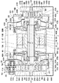
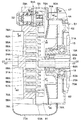
図中、1はスクロール式空気圧縮機の外枠を構成する略筒状のケーシングで、該ケーシング1は、後述の固定スクロール7A,7Bと共に固定側部材を構成するものである。そして、ケーシング1は、図1、図2に示す如く、軸線O1−O1を中心として略円筒状に形成され軸方向の両側が開口した中間ケース2と、該中間ケース2の左,右両側に取付けられた左,右の外側ケース3A,3Bとにより構成されている。
In the figure,
ここで、中間ケース2の軸方向一側(図2中の左側)に位置する第1の外側ケース3Aは、図5、図6に示す如く、軸方向の一側が開口し他側が閉塞した略有底筒状に形成されている。そして、外側ケース3Aは、例えばねじ止め等の手段によって中間ケース2の一端側に取付けられた有底筒状のファン収容部4Aと、該ファン収容部4Aの一端側に拡径して形成され、略三角形の筒状をなすスクロール収容部5Aとにより構成されている。
Here, as shown in FIGS. 5 and 6, the first outer case 3 </ b> A located on one side in the axial direction of the intermediate case 2 (left side in FIG. 2) is substantially open with one side in the axial direction open and the other side closed. It is formed in a bottomed cylindrical shape. The
一方、中間ケース2の軸方向他側(図2中の右側)に位置する第2の外側ケース3Bは、図5に示す如く、軸方向の一側が閉塞し他側が開口した有底筒状に形成されている。また、外側ケース3Bは、中間ケース2の他端側に取付けられた有底筒状のファン収容部4Bと、該ファン収容部4Bの他端側に形成されたスクロール収容部5Bとにより構成されている。
On the other hand, as shown in FIG. 5, the second
そして、外側ケース3A,3Bのファン収容部4A,4Bには、後述の冷却ファン38A,38Bが収容され、スクロール収容部5A,5Bには、後述の旋回スクロール26A,26Bが収容されるものである。
The
また、第1の外側ケース3Aは、後述する第1の固定スクロール7A、第1の旋回スクロール26A等と共に低圧段の圧縮部6Aを構成し、第2の外側ケース3Bは、第2の固定スクロール7B、第2の旋回スクロール26B等と共に高圧段の圧縮部6Bを構成している。この場合、低圧段と高圧段の圧縮部6A,6Bは互いにほぼ同一の構成要素を有しているので、以下の説明では、低圧段の構成要素に符号「A」を付して説明し、高圧段の構成要素については、符号「B」を付して説明すると共に、低圧段と重複する説明を省略するものとする。
Further, the first
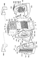
7Aはケーシング1の外側ケース3Aの開口側に設けられた低圧段の固定スクロールで、該固定スクロール7Aは、図2、図3に示す如く、ケーシング1の軸線O1−O1を中心として配設された略円板状の鏡板8Aと、該鏡板8Aの表面に立設された渦巻状のラップ部9Aと、鏡板8Aの外周側から該ラップ部9Aを取囲むように軸方向に突出した筒部10Aと、該筒部10Aの外周側から径方向外向きに突出し、ボルト等を介して外側ケース3Aの開口側に着脱可能に取付けられたフランジ部11Aとにより構成されている。
ここで、鏡板8Aの外周側には、図5に示す如く、例えば空気等の流体を吸込む2箇所の吸込口12Aが設けられ、鏡板8Aの中心側には圧縮空気の吐出口13Aが設けられている。また、鏡板8Aの裏面には、後述する冷却風の流れ方向(図2中の矢示A3方向)に沿って垂直方向に延びる複数の固定側冷却フィン14Aが立設されている。
Here, as shown in FIG. 5, two
7Bはケーシング1の外側ケース3Bの開口側に設けられた高圧段の固定スクロールで、該固定スクロール7Bは、低圧段の固定スクロール7Aとほぼ同様に、鏡板8B、ラップ部9B、筒部10B、フランジ部11B等により構成され、鏡板8Bの背面側には、冷却風の流れ方向(図2中の矢示B3方向)に沿って垂直方向に延びる複数の固定側冷却フィン14Bが立設されている。
7B is a fixed scroll of a high pressure stage provided on the opening side of the
15はケーシング1の中間ケース2内に設けられた電動機としての電動モータで、該電動モータ15は、図2に示す如く、低圧段の固定スクロール7Aと高圧段の固定スクロール7Bとの間に配置され、中間ケース2の内周側に固定された筒状のステータ16と、該ステータ16の内周側に回転可能に配設された筒状のロータ17等とにより構成されている。そして、電動モータ15は、後述の回転軸18を軸線O1−O1を中心として回転駆動するものである。
18はケーシング1に回転可能に設けられた回転軸で、該回転軸18は、例えば段付円筒状の中空ロッドからなり、軸方向の中間部位が電動モータ15のロータ17内に嵌着され、軸線O1−O1を中心としてロータ17と一体に回転するものである。また、回転軸18は、軸方向の両側が回転軸受19A,19Bを介して外側ケース3A,3B(ファン収容部4A,4B)の底部側に回転可能に支持されている。
20Aは回転軸18の一端側に取付けられた略円筒状の偏心ブッシュで、該偏心ブッシュ20Aの内周側には、図3に示す如く、回転軸嵌合孔21Aと連結軸嵌合孔22Aとが形成され、これらは互いに連通して軸方向に延びている。
ここで、回転軸嵌合孔21A内には、例えば圧入等の手段によって回転軸18が嵌合、固着され、回転軸18と偏心ブッシュ20Aとは一体に回転する構成となっている。また、連結軸嵌合孔22Aは、回転軸嵌合孔21Aよりも大径に形成され、その中心は回転軸嵌合孔21Aの中心(軸線O1−O1)から寸法δ(偏心量δ)だけ偏心している。
Here, the
そして、連結軸嵌合孔22A内には、後述の偏心軸受25Aを介して連結軸23が回転可能に嵌合されている。これにより、連結軸23を軸線O1−O1に対して偏心量δだけ偏心させたとしても、偏心ブッシュ20Aの外周面は、偏心量δに関与しない形状(即ち、軸線O1−O1を中心とした円筒状)に形成することができる。
A connecting
20Bは回転軸18の他端側に取付けられた略円筒状の偏心ブッシュで、該偏心ブッシュ20Bは、図4に示す如く、一端側の偏心ブッシュ20Aとほぼ同様に、回転軸嵌合孔21Bと連結軸嵌合孔22Bとを有している。
23は回転軸18内に挿通して設けられた連結軸で、該連結軸23は、図2に示す如く、例えば段付円柱状のロッドからなり、その軸方向の両側は回転軸18から軸方向に突出した円柱状のクランク部24A,24Bとなっている。そして、これらのクランク部24A,24Bには、後述する旋回スクロール26A,26Bのボス部29A,29Bが連結されている。
また、連結軸23は、偏心軸受25A,25Bと偏心ブッシュ20A,20Bとを介して回転軸18に相対回転可能に取付けられ、回転軸18等の軸線O1−O1に対して寸法δだけ偏心した偏心軸線O2−O2上に配置されている。そして、連結軸23は、回転軸18が回転するときに、旋回スクロール26A,26Bと一緒に旋回運動するものである。
Further, the connecting
26Aは固定スクロール7Aと対面してケーシング1内に旋回可能に設けられた低圧段の旋回スクロールで、該低圧段の旋回スクロール26Aは、図3に示す如く、略円板状に形成された鏡板27Aと、該鏡板27Aの表面に立設された渦巻状のラップ部28Aと、鏡板27Aの裏面に立設された筒状のボス部29Aとにより大略構成されている。
26A is a low-pressure stage orbiting scroll provided facing the fixed
26Bは固定スクロール7Bと対面して設けられた高圧段の旋回スクロールで、該旋回スクロール26Bは、図4に示す如く、低圧段の旋回スクロール26Aとほぼ同様に、鏡板27B、ラップ部28B、ボス部29B等により構成されている。
ここで、鏡板27A,27Bは、外側ケース3A,3Bのスクロール収容部5A,5B内に収容されている。また、鏡板27A,27Bの裏面には、複数の旋回側冷却フィン30A,30Bが立設され、これらの冷却フィン30A,30Bは、後述する冷却風の流れ方向(図5中の矢示A1,B1方向)にほぼ沿って固定側冷却フィン14A,14Bと直交するように水平方向に延びている。
Here, the
また、ラップ部28A,28Bは、固定スクロール7A,7Bのラップ部9A,9Bと所定の角度(例えば180度)だけずらして重なり合うように配設され、これによって低圧段のラップ部9A,28A間には、外周側から内周側にわたって複数の圧縮室31Aが画成されると共に、高圧段のラップ部9B,28B間にも、外周側から内周側にわたって複数の圧縮室31Bが画成されている。
Further, the
さらに、ボス部29A,29Bは、連結軸23のクランク部24A,24Bにそれぞれボルト(図示せず)等を用いて一体に固定されている。そして、旋回スクロール26A,26Bは、電動モータ15により回転軸18、連結軸23等を介して駆動され、偏心量δに応じた一定の旋回半径をもって旋回運動を行うことにより、各圧縮室31A,31Bで空気の圧縮動作を行うと共に、その旋回動作時には、自転防止機構としての補助クランク32(図2参照)によって自転が防止されるものである。
Further, the
一方、低圧段の各吸込口12Aには、図1に示す如く、サイレンサ33がそれぞれ設けられている。また、低圧段の吐出口13Aには配管34が接続され、この配管34は冷却器47を介して配管35に接続されている。そして、配管35は、高圧段の吸込口(図示せず)に接続されている。
On the other hand, as shown in FIG. 1,
さらに、高圧段の吐出口13Bには他の配管36が接続され、この配管36は冷却器47を介して配管37に接続されている。そして、配管37は外部の空気タンク(図示せず)等に接続されている。これにより、本実施の形態の空気圧縮機は、サイレンサ33から吸込んだ空気を低圧段と高圧段の圧縮部6A,6Bによって順次圧縮する2段式の圧縮機として構成されている。
Further, another
38Aは回転軸18の軸方向一側に設けられた第1の冷却ファンとしての低圧段の冷却ファンで、該冷却ファン38Aは、図3、図6に示す如く、例えば遠心ファン等からなり、回転軸18の外周側に偏心ブッシュ20Aを介して嵌合されると共に、廻止め用のキー部材39Aを用いて偏心ブッシュ20Aに固定されている。また、冷却ファン38Aは、ケーシング1内で外側ケース3Aのファン収容部4A内に収容され、電動モータ15と低圧段の旋回スクロール26Aとの間に配置されている。
38A is a low-pressure stage cooling fan as a first cooling fan provided on one side in the axial direction of the
38Bは回転軸18の軸方向他側に設けられた第2の冷却ファンとしての高圧段の冷却ファンで、該冷却ファン38Bは、図4に示す如く、例えば冷却ファン38Aと同じ形状を有する遠心ファン等からなり、偏心ブッシュ20Bを介して回転軸18に取付けられると共に、電動モータ15と高圧段の旋回スクロール26Bとの間に位置して外側ケース3Bのファン収容部4B内に収容されている。
38B is a high-pressure stage cooling fan as a second cooling fan provided on the other side in the axial direction of the
そして、冷却ファン38A,38Bは、電動モータ15の軸方向両側に位置して旋回スクロール26A,26Bと対向し、この位置で回転軸18と一緒に回転することによって固定スクロール7A,7Bの裏面側、旋回スクロール26A,26Bの裏面側及び後述の冷却器47に冷却風を供給するものである。
The cooling
40Aは外側ケース3A内に設けられた第1の仕切板としての低圧段の仕切板で、該仕切板40Aは、例えば環状の金属板、樹脂板等からなり、低圧段の旋回スクロール26Aと冷却ファン38Aとの間(ファン収容部4Aとスクロール収容部5Aとの間)を仕切る位置に取付けられている。
また、仕切板40Aの中央には、旋回スクロール26Aのボス部29Aの外周側に隙間をもって挿通される開口部41Aが形成され、この開口部41Aは、仕切板40Aにより画成されたファン収容部4A内の空間とスクロール収容部5A内の空間とを連通している。
In addition, an
40Bは外側ケース3B内に設けられた第2の仕切板としての高圧段の仕切板で、該仕切板40Bは、低圧段の仕切板40Aとほぼ同様に、内周側に開口部41Bが形成された環状の金属板、樹脂板等からなり、高圧段の旋回スクロール26Bと冷却ファン38Bとの間(ファン収容部4Bとスクロール収容部5Bとの間)を仕切る位置に取付けられている。
42Aは外側ケース3Aのスクロール収容部5Aに例えば2箇所設けられた第1の流入口としての低圧段の流入口で、該各流入口42Aは、図1、図5に示す如く、スクロール収容部5Aの開口端に設けた切欠きと固定スクロール7Aのフランジ部11Aとの間に形成され、スクロール収容部5Aの水平方向(左,右方向)の両側で側面に開口している。
42A is a low-pressure stage inlet serving as a first inlet provided in, for example, two places in the
42Bは外側ケース3Bのスクロール収容部5Bに例えば2箇所設けられた第2の流入口としての高圧段の流入口で、該各流入口42Bは、低圧段の流入口42Aとほぼ同様に、スクロール収容部5Bの水平方向(左,右方向)の両側で側面に開口している。
42B is a high-pressure stage inlet as a second inlet provided, for example, in two places in the
そして、冷却ファン38A,38Bの作動時には、外部の空気が各流入口42A,42Bからスクロール収容部5A,5B内に吸込まれて冷却風となり、これらの冷却風は略水平方向に流通しつつ、旋回スクロール26A,26Bの裏面側を冷却する。
When the cooling
43Aは外側ケース3Aのファン収容部4Aに例えば2箇所設けられた第1の流出口としての低圧段の流出口で、該各流出口43Aは、ファン収容部4Aの垂直方向(上,下方向)の両側で側面に開口している。この場合、流入口42Aと流出口43Aとは、仕切板40Aを挟んで互いに軸方向の反対側(旋回スクロール26A側と冷却ファン38A側)に離間して配置されると共に、外側ケース3Aの周方向に対して互いに異なる位置に形成されている。
43A is a low-pressure stage outlet as a first outlet provided, for example, in two places in the
43Bは外側ケース3Bのファン収容部4Bに例えば2箇所設けられた第2の流出口としての高圧段の流出口で、該各流出口43Bは、低圧段の流出口43Aとほぼ同様に、ファン収容部4Bの垂直方向の両側で側面に開口し、仕切板40Bを挟んで流入口42Bと軸方向の反対側に配置されている。
43B is an outlet of a high-pressure stage as a second outlet provided, for example, in two places in the
そして、冷却ファン38Aの作動時には、スクロール収容部5A,5B内の冷却風が仕切板40A,40Bの開口部41A,41Bを介してファン収容部4A,4B内に吸込まれ、これらの冷却風は、図2中の矢示A2,B2に示す如く、各流出口43Aから後述のダクト44A,46A内に流出すると共に、各流出口43Bから後述のダクト44B,46B内に流出する。
During the operation of the cooling
44Aは外側ケース3Aの下部側に設けられた第1(低圧段)のスクロール用ダクトで、該スクロール用ダクト44Aは、例えば中空のボックス状に形成され、下側の流出口43Aを覆う位置から後述する下側の固定スクロール用通気口45A(固定側冷却フィン14A)の位置まで延びると共に、これらの流出口43Aと通気口45Aとを接続している。
44A is a first (low pressure stage) scroll duct provided on the lower side of the
44Bは外側ケース3Bの下部側に設けられた第2(高圧段)のスクロール用ダクトで、該スクロール用ダクト44Bは、低圧段のダクト44Aとほぼ同様に、下側の流出口43Bを覆う位置から後述する下側の固定スクロール用通気口45Bの位置まで延び、これらの流出口43Bと通気口45Bとを接続している。
44B is a second (high-pressure stage) scroll duct provided on the lower side of the
そして、スクロール用ダクト44A,44Bは、下側の流出口43A,43Bから流出される冷却風を固定スクロール7A,7Bの裏面側にそれぞれ導くことにより、鏡板8A,8B等を冷却する。
The
45Aは低圧段の固定スクロール7Aの上,下両側に設けられた第1の固定スクロール用通気口で、これら第1の固定スクロール用通気口45Aは、固定側冷却フィン14Aの両端側となる位置で固定スクロール7Aの外面側に開口して形成されている。そして、固定スクロール用通気口45Aは、ダクト44A内を流れる冷却風を固定側冷却フィン14Aに沿って鏡板8Aの裏面側に流通させるものである。また、高圧段の固定スクロール7Bにも同様に、第2の固定スクロール用通気口45Bが設けられている。
46Aは外側ケース3Aに設けられた第1(低圧段)の冷却器用ダクトで、該冷却器用ダクト46Aは、例えば中空のボックス状に形成され、上側の流出口43Aを覆うと共に、この流出口43Aと後述の冷却器47との間に接続されている。
46Bは外側ケース3Bに設けられた第2(高圧段)の冷却器用ダクトで、該冷却器用ダクト46Bは、低圧段のダクト46Aとほぼ同様に、上側の流出口43Bと冷却器47との間に接続されている。
46B is a second (high pressure stage) cooler duct provided in the
そして、これら2個の冷却器用ダクト46A,46Bは、冷却ファン38A,38Bが回転するときに、上側の流出口43A,43Bから流出する冷却風を冷却器47の内部に導くものである。
The two
また、図1において、47はケーシング1(中間ケース2)の上側に設けられた冷却器で、該冷却器47内には、各配管34,35,36,37がジクザグ状に屈曲して配置され、これらの配管34〜37は冷却ファン38A,38Bの冷却風によって放熱される。そして、冷却器47は、例えば低圧段の圧縮室31Aから吐出されて高圧段の圧縮室31Bに吸込まれる中間圧の圧縮空気を冷却するインタークーラと、圧縮室31Bから吐出される高圧の圧縮空気を冷却するアフタークーラとを一体化したツインクーラとして構成されている。
In FIG. 1,
一方、図2において、48Aは低圧段の外側ケース3A内でスクロール7A,26Aと仕切板40Aとの間に形成されたスクロール・仕切板間空間で、該スクロール・仕切板間空間48Aは、旋回スクロール26Aの鏡板27Aの裏面側に面して配置され、この空間48Aには流入口42Aが開口している。
On the other hand, in FIG. 2,
また、49Aは外側ケース3A内でモータ15と仕切板40Aとの間に形成されたモータ・仕切板間空間で、該モータ・仕切板間空間49Aには、冷却ファン38Aが収容されると共に、流出口43Aが開口している。さらに、高圧段の外側ケース3B内にも同様に、仕切板40Bによってスクロール・仕切板間空間48Bとモータ・仕切板間空間49Bとが画成されている。
Further, 49A is a motor / partition plate space formed between the
本実施の形態によるツインラップ型のスクロール式空気圧縮機は、上述の如き構成を有するもので、次にその作動について説明する。 The twin wrap type scroll type air compressor according to the present embodiment has the above-described configuration, and the operation thereof will be described next.
まず、電動モータ15に給電すると、そのロータ17により回転軸18が軸線O1−O1を中心として回転駆動される。これにより、回転軸18内に偏心した状態で取付けられた連結軸23が旋回運動を行うと、その両端側に連結された旋回スクロール26A,26Bは、固定スクロール7A,7Bに対して寸法δの旋回半径をもった旋回動作を行う。
First, when electric power is supplied to the
この結果、低圧段の圧縮部6Aでは、固定スクロール7Aの外周側に設けた吸込口12Aからサイレンサ33を介して外気を吸込みつつ、この空気を各圧縮室31A内で順次圧縮する。そして、低圧段の圧縮室31A内で圧縮された中間圧の圧縮空気は、固定スクロール7Aの吐出口13Aから配管34を介して冷却器47に吐出される。
As a result, the
また、高圧段の圧縮部6Bでは、低圧段の圧縮部6Aで圧縮された中間圧の圧縮空気が冷却器47から配管35を介して固定スクロール7Bの吸込口に供給されると、この圧縮空気を各圧縮室31B内でさらに圧縮し、高圧の圧縮空気を吐出口13Bから配管36に吐出する。この圧縮空気は、冷却器47で冷やされ、他の配管37を介して空気タンク等に貯留される。
Further, in the high-pressure
次に、空気圧縮機を冷却する冷却風の流れについて説明すると、まず回転軸18が回転すると、その外周側に取付けられた冷却ファン38A,38Bが回転駆動される。これにより、外側ケース3A,3B内の空気が遠心力によって流出口43A,43Bから外部に流出すると、側面の流入口42A,42Bからスクロール・仕切板間空間48A,48B内に外気が冷却風として吸込まれる。
Next, the flow of cooling air for cooling the air compressor will be described. First, when the rotating
そして、この冷却風は、図3ないし図5中の矢示A1,B1に示す如く、旋回スクロール26A,26Bの裏面側を経由してスクロール・仕切板間空間48A,48B内に吸込まれるときに、旋回側冷却フィン30A,30Bに沿ってほぼ水平方向に流れ、旋回スクロール26A,26Bの外周側から中央部位(開口部41A,41Bの位置)まで長い距離にわたって鏡板27A,27B、旋回側冷却フィン30A,30B等と接触するので、これらを効率よく冷却することができる。
When the cooling air is sucked into the
また、この冷却風は、冷却ファン38A,38Bの回転によって仕切板40A,40Bの開口部41A,41Bからモータ・仕切板間空間49A,49B内に吸込まれ、その一部は、図3,図4中の矢示A2,B2に示す如く、下側の流出口43A,43Bからスクロール用ダクト44A,44B内に流出される。そして、スクロール用ダクト44A,44B内に流出された冷却風は、矢示A3,B3に示す如く、固定側冷却フィン14A,14Bに沿ってほぼ垂直方向に流れるようになり、固定スクロール7A,7Bの鏡板8A,8B等を裏面側から冷却することができる。
Further, the cooling air is sucked into the motor-
一方、モータ・仕切板間空間49A,49B内に吸込まれた冷却風の一部は、矢示A4,B4に示す如く、上側の流出口43A,43Bから冷却器用ダクト46A,46B内に流出される。そして、この冷却風は、冷却器用ダクト46A,46Bに導かれて冷却器47内を通過することにより、高圧段の圧縮部6Bに吸込まれる中間圧の圧縮空気や圧縮部6Bから吐出される高圧の圧縮空気を冷却することができる。
On the other hand, a part of the cooling air sucked into the motor /
かくして、本実施の形態によれば、回転軸18の軸方向両側には、第1,第2の旋回スクロール26A,26Bと対向する位置に第1,第2の冷却ファン38A,38Bを設け、ケーシング1の外側ケース3A,3Bには、これらの冷却ファン38A,38Bに対応して第1,第2の流入口42A,42B、第1,第2の流出口43A,43B、第1,第2のスクロール用ダクト44A,44B、第1,第2の冷却器用ダクト46A,46B等を設ける構成としている。
Thus, according to the present embodiment, the first and
これにより、圧縮機の作動時には、電動モータ15により回転軸18を駆動して第1,第2の旋回スクロール26A,26Bを旋回運動させることができ、このときに2個の冷却ファン38A,38Bを旋回スクロール26A,26Bと対面する位置で一緒に回転させることができる。
Thereby, when the compressor is operated, the
この結果、各冷却ファン38A,38Bは、図5中の矢示A1,B1に示す如く、流入口42A,42Bから旋回スクロール26A,26Bの裏面側に冷却風をそれぞれ吸込むことができ、これらの冷却風によって旋回側の鏡板27A,27B等を効率よく冷却することができる。
As a result, each of the cooling
そして、これらの冷却風を流出口43A,43Bからスクロール用ダクト44A,44Bに流出して固定スクロール7A,7Bの裏面側に導くことができ、これによって図2中の矢示A3,B3に示す如く、固定側の鏡板8A,8B等も効率よく冷却することができる。
Then, these cooling winds can flow out from the
従って、圧縮機の動力源となる電動モータ15を利用して冷却ファン38A,38Bを駆動でき、従来技術のように2個の電動ファン等を用いる必要がないから、電動ファン等の部品点数を削減してコストダウンを促進できると共に、電動ファンによる騒音や発熱、消費電力等を抑えることができる。
Accordingly, the cooling
また、冷却ファン38A,38Bを電動モータ15の軸方向両側に並べて配置できるから、ケーシング1の外側に電動モータ等の構造物を取付ける必要がなくなり、圧縮機全体を径方向に小型化することができる。そして、ケーシング1や旋回スクロール26A,26Bの構造を複雑化しなくても、ケーシング1の軸方向両側で広い範囲にわたって冷却性能を高めることができる。これにより、2箇所の圧縮部6A,6Bを備えた空気圧縮機においても、冷却用の構造を簡略化することができ、その組立等を効率よく行うことができる。
Further, since the cooling
また、ケーシング1の上側には冷却器47を設け、流入口42A,42Bはケーシング1の外側ケース3A,3Bの側面に形成し、流出口43A,43Bは外側ケース3A,3Bの上側と下側とにそれぞれ形成している。そして、下側の流出口43A,43Bにはスクロール用ダクト44A,44Bを接続し、上側の流出口43A,43Bには冷却器用ダクト46A,46Bを接続している。
Further, a cooler 47 is provided on the upper side of the
このため、冷却器47は、例えば高圧段の圧縮部6Bに吸込まれる中間圧の圧縮空気や、圧縮部6Bから吐出される高圧の圧縮空気等を冷却でき、その圧縮効率を高めたり、圧縮空気の除湿等を行うことができると共に、これによって圧縮機の性能を向上させることができる。
For this reason, the cooler 47 can cool, for example, compressed air of intermediate pressure sucked into the
そして、冷却ファン38A,38Bの作動時には、側面の流入口42A,42Bから旋回スクロール26A,26Bの裏面側に冷却風を吸込みつつ、この冷却風の一部を下側の流出口43A,43Bからスクロール用ダクト44A,44Bに流出できると共に、さらに冷却風の一部を上側の流出口43A,43Bから冷却器用ダクト46A,46Bに流出することができる。これにより、各固定スクロール7A,7B、各旋回スクロール26A,26B及び冷却器47をそれぞれ効率よく冷却でき、圧縮機の冷却性能を高めることができる。
When the cooling
この場合、流入口42A,42B、下側の流出口43A,43B(スクロール用ダクト44A,44B)及び上側の流出口43A,43B(冷却器用ダクト46A,46B)を、外側ケース3A,3Bの周方向に対して互いに異なる位置に配設でき、流入口42A,42Bを避けるように各ダクト44A,44B,46A,46Bを引回さずに済むので、流入口42A,42Bを十分な大きさに形成しつつ、ダクトの形状を簡略化することができる。
In this case, the
また、冷却器47と各ダクト44A,44B,46A,46Bとをケーシング1の上側及び下側に重なり合うようにコンパクトに配置でき、これによって圧縮機全体を水平方向に対して容易に小型化できると共に、複数のダクトや冷却器47を備えた圧縮機であっても、その設置面積を小さく抑えることができる。
Further, the cooler 47 and the
また、外側ケース3A,3Bのファン収容部4A,4Bとスクロール収容部5A,5Bとの間には、内周側が開口部41A,41Bとなった環状の仕切板40A,40Bを設けたので、これらの仕切板40A,40Bによってファン収容部4A,4B内の空間とスクロール収容部5A,5B内の空間とを仕切ることができ、この状態でスクロール収容部5A,5Bには流入口42A,42Bを開口させ、ファン収容部4A,4Bには流出口43A,43Bを開口させることができる。
In addition, since the
これにより、冷却ファンの作動時には、流入口42A,42Bから旋回スクロール26A,26Bの裏面中央(開口部41A,41Bの位置)まで長い距離にわたって冷却風を吸込むことができ、冷却風が旋回スクロール26A,26Bの鏡板27A,27B、冷却フィン30A,30B等に接触する距離を長くすることができる。従って、仕切板40A,40Bを用いた簡単な構造で旋回スクロール26A,26Bや冷却ファン38A,38Bに面した冷却風の通路を形成でき、旋回スクロール26A,26B等の冷却を安定的に行うことができる。
Accordingly, when the cooling fan is operated, the cooling air can be sucked in over a long distance from the
一方、固定スクロール7A,7Bの鏡板8A,8Bの裏面には、垂直方向に延びる固定側冷却フィン14A,14Bを設け、旋回スクロール26A,26Bの鏡板27A,27Bの裏面には、水平方向に延びる旋回側冷却フィン30A,30Bを設けたので、側面の流入口42A,42Bから吸込まれる冷却風を旋回側冷却フィン30A,30Bに沿って水平方向に流通させることができ、また下側の流出口43A,43Bから固定スクロール7A,7Bの裏面下側に導かれる冷却風を、固定側冷却フィン14A,14Bに沿って上側に流通させることができる。従って、固定スクロール7A,7Bと旋回スクロール26A,26Bの冷却効率をより一層高めることができる。
On the other hand, fixed-
また、ケーシング1を、中間ケース2及び外側ケース3A,3Bからなる3部材によって形成したので、外側ケース3Aには、第1の固定スクロール7A、旋回スクロール26A及び冷却ファン38Aを配置できると共に、外側ケース3Bには、第2の固定スクロール7B、旋回スクロール26B及び冷却ファン38Bを配置でき、ケーシング1の構造を簡略化して圧縮機の組立作業を効率よく行うことができる。
In addition, since the
さらに、回転軸18の両端に偏心ブッシュ20A,20Bを設け、各偏心ブッシュ20A,20Bの内周側に偏心軸受25A,25Bを介して連結軸23を設けたので、偏心ブッシュ20A,20Bの外周側は、連結軸23の偏心量δに関係なく、軸線O1−O1を中心とした円筒面として容易に形成でき、これらの部位に冷却ファン38A,38Bを取付けて安定的に回転させることができる。
Furthermore, since the
この場合、回転軸18が一方向に回転するときに、例えば圧縮部6A側からみた冷却ファン38Aの回転方向と、圧縮部6B側からみた冷却ファン38Bの回転方向とは、互いに逆向きとなる。しかし、冷却ファン38A,38Bを、何れの方向に回転した場合でも送風動作が可能な遠心ファンにより構成したので、これらの冷却ファン38A,38Bを同一形状の部品として形成でき、圧縮機全体の部品点数を削減してコストダウンや生産性の向上を図ることができる。
In this case, when the rotating
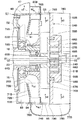
次に、図7ないし図11は本発明による第2の実施の形態を示し、本実施の形態の特徴は、低圧側の圧縮部と高圧側の圧縮部とで冷却構造を異ならしめる構成としたことにある。なお、本実施の形態では、前記第1の実施の形態と同一の構成要素に同一の符号を付し、その説明を省略するものとする。 Next, FIG. 7 to FIG. 11 show a second embodiment according to the present invention. The feature of this embodiment is that the cooling structure is made different between the low pressure side compression section and the high pressure side compression section. There is. In the present embodiment, the same components as those in the first embodiment are denoted by the same reference numerals, and the description thereof is omitted.
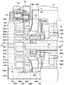
51は後述の固定スクロール55A,55Bと共に固定側部材を構成するケーシングで、該ケーシング51は、図7、図8に示す如く、第1の実施の形態とほぼ同様に、軸方向の両側が開口した略円筒状の中間ケース52と、有底筒状に形成され、底部側が該中間ケース52の軸方向一側,他側に取付けられた第1,第2の外側ケース53A,53Bとによって構成されている。
そして、第1の外側ケース53Aは、ファン収容部4Aおよびスクロール収容部5Aからなり、後述する第1の固定スクロール55A、第1の旋回スクロール66A等と共に低圧段の圧縮部54Aを構成している。また、第2の外側ケース53Bは、ファン収容部4Bおよびスクロール収容部5Bからなり、第2の固定スクロール55B、第2の旋回スクロール66B等と共に高圧段の圧縮部54Bを構成している。外側ケース53A,53Bのファン収容部4A,4Bには、後述の冷却ファン71A,71Bが収容され、スクロール収容部5A,5Bには、後述の旋回スクロール66A,66Bが収容されるものである。
The first
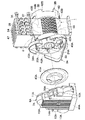
55Aは外側ケース53Aに取付けられた低圧段の固定スクロールで、該固定スクロール55Aは、図9に示す如く、第1の実施の形態とほぼ同様に、鏡板56A、ラップ部57A、筒部58A、フランジ部59A、吸込口60A(図7参照)、吐出口61A、固定側冷却フィン62A等によって構成されている。
55A is a low-pressure stage fixed scroll attached to the
また、55Bは外側ケース53Bに取付けられた高圧段の固定スクロールで、該固定スクロール55Bは、図10に示す如く、低圧段とほぼ同様に、鏡板56B、ラップ部57B、筒部58B、フランジ部59B、吸込口(図示せず)、吐出口61B、固定側冷却フィン62B等によって構成されている。
55B is a fixed scroll of a high-pressure stage attached to the
そして、固定スクロール55A,55Bの間には、第1の実施の形態とほぼ同様に、回転軸受19A,19Bを介して外側ケース53A,53Bの底部側に回転可能に支持された回転軸18が設けられ、この回転軸18の両端側には偏心ブッシュ63A,63Bが嵌着されている。
Between the fixed
この場合、偏心ブッシュ63A,63Bには、回転軸18が嵌着された回転軸嵌合孔64A,64Bと、連結軸23が偏心軸受25A,25Bを介して回転可能に嵌合された連結軸嵌合孔65A,65Bとが形成されている。これにより、連結軸23は、図8に示す如く、偏心軸受25A,25Bと偏心ブッシュ63A,63Bとを介して回転軸18に回転可能に取付けられ、回転軸18に対して寸法δだけ偏心している。
In this case, the rotation shaft
66Aは低圧段の旋回スクロールで、該旋回スクロール66Aは、第1の実施の形態とほぼ同様に、鏡板67A、ラップ部68A、ボス部69A、旋回側冷却フィン70A等によって構成されている。また、66Bは高圧段の旋回スクロールで、該旋回スクロール66Bは、低圧段とほぼ同様に、鏡板67B、ラップ部68B、ボス部69B、旋回側冷却フィン70B等によって構成されているものの、旋回側冷却フィン70Bは、後述する冷却風の流れ方向(図10中の矢示b4方向)にほぼ沿って垂直方向に延びている。
次に、71Aは回転軸18の軸方向一側に設けられた第1の冷却ファンとしての低圧段の冷却ファンで、該第1の冷却ファン71Aは、図9に示す如く、第1の実施の形態とほぼ同様に、例えば遠心ファン等によって構成され、外側ケース53A内に収容されると共に、偏心ブッシュ63Aを用いて回転軸18の軸方向一側に取付けられている。
Next, 71A is a low-pressure stage cooling fan as a first cooling fan provided on one side in the axial direction of the
また、外側ケース53A内には、冷却ファン71Aと旋回スクロール66Aとの間を仕切る第1の仕切板としての環状の仕切板72Aが設けられ、その中央部には開口部73Aが形成されている。さらに、外側ケース53Aのスクロール収容部5Aには、第1の流入口75Aが設けられると共に、外側ケース53Aには、ファン収容部4Aの側面に開口した第1の流出口76Aが設けられている。また、外側ケース53Aには、第1のスクロール用ダクト77A、第1の固定スクロール用通気口78A、第1の冷却器用ダクト80Aが取付けられている。
Further, an
このように、低圧段の圧縮部54Aの冷却構造は、第1の実施の形態とほぼ同様に構成されている。そして、圧縮機の運転時には、回転軸18と一緒に冷却ファン71Aが回転駆動されることにより、図9中の矢示a1,a2,a3,a4方向に冷却風が発生し、固定スクロール55Aの裏面側、旋回スクロール66Aの裏面側及び冷却器47に冷却風が供給される。
Thus, the cooling structure of the low-pressure
一方、71Bは回転軸18の軸方向他側に設けられた第2の冷却ファンとしての高圧段の冷却ファンで、該第2の冷却ファン71Bは、図10に示す如く、第1の実施の形態とほぼ同様に、例えば遠心ファン等によって構成され、外側ケース53B内に収容されると共に、偏心ブッシュ63Bを用いて回転軸18の軸方向他側に取付けられている。
On the other hand, 71B is a high-pressure stage cooling fan as a second cooling fan provided on the other axial side of the
しかし、第1の実施の形態では、冷却ファン38Bが流入口42Bから旋回スクロール26Bの裏面側を経由して冷却風を吸込み、この冷却風を固定スクロール7Bの裏面側に供給する構成となっている。
However, in the first embodiment, the cooling
これに対し、本実施の形態では、冷却ファン71Bが軸方向に対して第1の実施の形態と逆向きに配置されている。そして、冷却ファン71Bは、後述の如く流入口75Bから外側ケース53Bの底部側に冷却風を吸込み、この冷却風を固定スクロール55Bの裏面側と旋回スクロール66Bの裏面側とに対して並列に供給する構成となっている。
On the other hand, in this embodiment, the cooling
72Bは外側ケース53B内に設けられた一の仕切板で、該仕切板72Bは、後述する他の仕切板74Bと共に第2の仕切板を構成するものである。これらの仕切板72B,74Bは、例えば環状の金属板、樹脂板等によって形成され、冷却ファン71Bを挟んで軸方向の一側,他側に配置されている。
72B is one partition plate provided in the
この場合、軸方向一側の仕切板72Bは、外側ケース53B内で電動モータ15側の空間と冷却ファン71Bとの間を仕切る位置に配設されている。また、仕切板72Bの内周側には、後述の流入口75Bから冷却ファン71Bの内周側(吸込側)に向けて冷却風が流通する開口部73Bが設けられている。
In this case, the partition plate 72B on one side in the axial direction is disposed at a position that partitions the space on the
74Bは外側ケース53B内に設けられた他の仕切板で、該仕切板74Bは、冷却ファン71Bの軸方向他側に配置され、外側ケース53B内で冷却ファン71Bと旋回スクロール66Bとの間を仕切る位置に配設されている。
74B is another partition plate provided in the
75Bは外側ケース53Bのファン収容部4Bに複数箇所設けられた第2の流入口を示し、これら第2の流入口75Bは、図7、図8、図11に示す如く、例えば外側ケース53Bの直径方向両側に形成され、外側ケース53Bの軸方向一側(仕切板72Bよりも電動モータ15側となる位置)に開口している。
75B shows a second inlet which kicked plurality箇Tokoro設 the
また、流入口75Bは、例えば回転軸受19B等と対面する位置に配設されている。このため、冷却ファン71Bの作動時には、図10中の矢示b1に示す如く、流入口75Bから外側ケース53B内に吸込まれる冷却風によって回転軸受19B等を効率よく冷却することができる。
Moreover, the
76Bは外側ケース53Bのファン収容部4Bに例えば2箇所設けられた第2の流出口で、これら第2の流出口76Bは、第1の実施の形態とほぼ同様に、外側ケース53Bの垂直方向(上,下方向)の両側で側面に形成されている。また、流出口76Bは冷却ファン71Bの径方向外側に配置され、仕切板72B,74Bの間で外側ケース53Bの軸方向中間部に開口している。
76B is a second outlet provided, for example, in two places in the
そして、冷却ファン71Bの作動時には、図10中の矢示b2に示す如く、外側ケース53B内を流れる冷却風が下側の流出口76Bからスクロール用ダクト77Aに流出し、また冷却風の一部は上側の流出口76Bから後述の冷却器用ダクト80Aに流出する構成となっている。
When the cooling
77Bは外側ケース53Bの外周側に設けられた第2のスクロール用ダクトで、該第2のスクロール用ダクト77Bは、例えば中空のボックス状に形成され、下側の流出口76Bを覆う位置から後述する下側の旋回スクロール用通気口79Bを経由して固定スクロール用通気口78Bの位置まで延びている。
77B is a second scroll duct provided on the outer peripheral side of the
そして、スクロール用ダクト77Bは、流出口76B、下側の固定スクロール用通気口78B及び旋回スクロール用通気口79Bを互いに接続し、流出口76Bから流出する冷却風を固定スクロール55Bの裏面側と旋回スクロール66Bの裏面側とに導くものである。
The
78Bは高圧段の固定スクロール55Bの上,下両側に設けられた第2の固定スクロール用通気口で、該第2の固定スクロール用通気口78Bは、固定側冷却フィン62Bの両端側となる位置で固定スクロール55Bの外面側に開口して形成されている。そして、固定スクロール用通気口78Bは、図10中の矢示b3に示す如く、スクロール用ダクト77B内を流れる冷却風を固定側冷却フィン62Bに沿って鏡板56Bの裏面側に流通させるものである。
79Bは外側ケース53Bの上,下両側に設けられた例えば2箇所の旋回スクロール用通気口で、これらの旋回スクロール用通気口79Bは、軸方向他側の仕切板74Bよりも旋回スクロール66B側に配置され、旋回スクロール66Bの径方向外側に位置してスクロール用ダクト77B内に開口している。
79B are, for example, two orbiting scroll vents provided on the upper and lower sides of the
また、下側の旋回スクロール用通気口79Bは、下側の流入口75Bと固定スクロール用通気口78Bとの間に配置されている。そして、旋回スクロール用通気口79Bは、図10中の矢示b4に示す如く、ダクト77B内を流れる冷却風の一部を旋回側冷却フィン70Bに沿って鏡板67Bの裏面側(後述のスクロール・仕切板間空間85)に流通させるものである。さらに、80Bは上側の流出口76Bに接続された第2の冷却器用ダクトで、該第2の冷却器用ダクト80Bは、上側の流出口76Bから流出する冷却風を冷却器47内に導く構成となっている。
The lower
一方、81は低圧段の外側ケース53A内でスクロール55A,66Aと仕切板72Aとの間に形成されたスクロール・仕切板間空間で、該スクロール・仕切板間空間81は、第1の実施の形態とほぼ同様に、旋回スクロール66Aの鏡板67Aの裏面側に面して配置され、この空間81内には流入口75Aが開口している。また、82は外側ケース53A内でモータ15と仕切板72Aとの間に形成されたモータ・仕切板間空間で、該モータ・仕切板間空間82には、冷却ファン71Aが収容されると共に、流出口76Aが開口している。
On the other hand,
さらに、83は高圧段の外側ケース53B内でモータ15と一の仕切板72Bとの間に形成されたモータ・仕切板間空間で、該モータ・仕切板間空間83には流入口75Bが開口している。また、84は外側ケース53B内で各仕切板72B,74Bの間に形成された仕切板間空間で、該仕切板間空間84には、冷却ファン71Bが収容されると共に、流出口76Bが開口している。また、85は外側ケース53B内でスクロール55B,66Bと他の仕切板74Bとの間に形成されたスクロール・仕切板間空間で、該スクロール・仕切板間空間85は、旋回スクロール66Bの鏡板67Bの裏面側に面して形成され、この空間85には旋回スクロール用通気口79Bが開口している。
Further,
本実施の形態によるツインラップ型のスクロール式空気圧縮機は、上述の如き構成を有するもので、次に冷却風の流れについて説明する。 The twin wrap type scroll air compressor according to the present embodiment has the above-described configuration, and the flow of cooling air will be described next.
まず、低圧段の圧縮部54Aでは、図9中の矢示a1,a2,a3,a4に示す如く、第1の実施の形態とほぼ同様の経路に沿って冷却風が流通する。この場合、冷却ファン71Aの作動時には、流入口75Aから旋回スクロール66Aの裏面側を経由してスクロール・仕切板間空間81内に冷却風が吸込まれる。そして、この冷却風は、モータ・仕切板間空間82から上,下の流出口76A,76Bを通じてダクト77A,80A内に流出し、固定スクロール55Aと冷却器47とをそれぞれ冷却する。
First, in the
一方、高圧段の圧縮部54Bでは、まず図10中の矢示b1に示す如く、冷却ファン71Bが作動することによって流入口75Bからモータ・仕切板間空間83内に冷却風が吸込まれ、この冷却風は、仕切板72Bの開口部73Bを通じて仕切板間空間84内に流入する。そして、仕切板間空間84内に流入した冷却風は、矢示b2に示す如く、冷却ファン71Bの外周側から吹き出すことによって下側の流出口76Bからスクロール用ダクト77B内に流出すると共に、上側の流出口76Bから冷却器用ダクト80B内に流出する。
On the other hand, in the
この場合、スクロール用ダクト77B内に流入した冷却風の一部は、矢示b3に示す如く、上,下の固定スクロール用通気口78Bによって固定スクロール55Bの裏面側を流通し、固定スクロール55Bを冷却する。また、残りの冷却風は、矢示b4に示す如く、上,下の旋回スクロール用通気口79Bによってスクロール・仕切板間空間85内を流通し、旋回スクロール66Bを冷却する。
In this case, as shown by the arrow b3, a part of the cooling air flowing into the
さらに、上側の流出口76Bから流出した冷却風は、矢示b5に示す如く、冷却器用ダクト80Bに導かれて冷却器47内に流入し、冷却器47の冷却効率を高めることができる。
Further, the cooling air flowing out from the
かくして、このように構成される本実施の形態でも、前記第1の実施の形態とほぼ同様の作用効果を得ることができる。そして、特に本実施の形態では、高圧段の冷却ファン71Bを第1の実施の形態と逆向きに配置し、外側ケース53Bに旋回スクロール用通気口79Bを設ける構成としている。
Thus, in the present embodiment configured as described above, it is possible to obtain substantially the same operational effects as those of the first embodiment. In particular, in the present embodiment, the cooling
これにより、高圧側の圧縮部54Bでは、流入口75Bから吸込んだ冷却風を2つの流れに分けて固定スクロール55Bと旋回スクロール66Bとにそれぞれ個別に供給でき、これらのスクロール55B,66Bを別々の冷却風によって並列に冷却することができる。
Thereby, in the
従って、例えば一方のスクロールを冷却することによって温められた冷却風が他方のスクロールに向けて流れることがないので、低い温度の冷却風によって各スクロール55B,66Bをそれぞれ効率よく冷却でき、冷却性能を高めることができる。
Therefore, for example, since the cooling air heated by cooling one scroll does not flow toward the other scroll, each of the
この場合、高圧段の外側ケース53B内には、冷却ファン71Bを挟んで2枚の仕切板72B,74Bを設けたので、これらの仕切板72B,74Bによって流入口75B、流出口76B及び旋回スクロール用通気口79Bの間をそれぞれ仕切ることができる。そして、外側ケース53B内には、モータ・仕切板間空間83、仕切板間空間84及びスクロール・仕切板間空間85からなる3つの空間を画成することができる。
In this case, since the two partition plates 72B and 74B are provided in the
これにより、冷却ファン71Bの作動時には、図10に示す如く、流入口75Bからモータ・仕切板間空間83内に吸込まれる矢示b1方向の冷却風と、仕切板間空間84から流出口76Bを通じてスクロール用ダクト77B内に流出する矢示b2方向の冷却風と、旋回スクロール用通気口79Bを通ってスクロール・仕切板間空間85を流れる矢示b4方向の冷却風とが混ざり合うのを防止でき、これら3つの冷却風の流れを各仕切板72B,74Bによって確実に分離することができる。従って、仕切板72B,74Bを用いた簡単な構造で冷却風の流れを安定的に形成することができる。
As a result, when the cooling
一方、低圧段の圧縮部54Aでは、第1の実施の形態とほぼ同様に、1つの冷却風の流れによって固定スクロール55Aと旋回スクロール66Aの両方を直列に冷却できるので、これら2個のスクロールを冷却するための冷却構造を簡略化することができる。
On the other hand, in the
このように、ツインラップ型のスクロール式空気圧縮機において、例えば運転中に比較的低い温度に保持される低圧段の圧縮部54Aでは冷却構造の簡略化を優先でき、また温度が上昇し易い高圧段の圧縮部54Bでは冷却効率を優先できるので、小型で高性能の圧縮機を容易に実現することができる。
In this way, in the twin wrap type scroll type air compressor, for example, in the low
なお、前記各実施の形態では、流入口42A,42B,75A,75Bを水平方向の側面に形成し、流出口43A,43B,76A,76Bを垂直方向(上,下方向)の側面に形成する構成とした。しかし、本発明はこれに限らず、流入口と流出口とは互いに干渉しない任意の位置に形成してよいものであり、例えば流入口を垂直方向(上,下方向)の側面に形成し、流出口を水平方向の側面に形成する構成としてもよい。
In each of the above embodiments, the
また、実施の形態では、回転軸18内に連結軸23を挿通して設け、その両端側のクランク部24A,24Bと回転軸18とを別部材として構成した。しかし、本発明はこれに限らず、回転軸の両端側にクランク部を一体に形成し、これらのクランク部には、軸受等を介して旋回スクロール26A,26Bのボス部29A,29Bを旋回可能に連結する構成としてもよい。
Further, in the embodiment, the connecting
また、実施の形態では、ケーシング1の上側にツインクーラからなる冷却器47を設ける構成とした。しかし、本発明はこれに限らず、例えば冷却器47を搭載しないスクロール式流体機械に適用してもよく、またインタークーラとアフタークーラのうち何れか一方のみを冷却器として搭載したスクロール式流体機械に適用してもよい。
In the embodiment, the cooler 47 made of a twin cooler is provided on the upper side of the
また、実施の形態では、スクロール式流体機械としてスクロール式空気圧縮機を例に挙げて説明した。しかし、本発明はこれに限らず、冷媒を圧縮する冷媒圧縮機、真空ポンプ等を含めて他のスクロール式流体機械に適用してもよい。 Further, in the embodiment, the scroll type air compressor has been described as an example of the scroll type fluid machine. However, the present invention is not limited to this, and may be applied to other scroll type fluid machines including a refrigerant compressor for compressing a refrigerant, a vacuum pump, and the like.
1,51 ケーシング
2,52 中間ケース
3A,3B,53A,53B 外側ケース
4A,4B ファン収容部
5A,5B スクロール収容部
6A,6B,54A,54B 圧縮部
7A,7B,55A,55B 固定スクロール
8A,8B,27A,27B,56A,56B,67A,67B 鏡板
9A,9B,28A,28B,57A,57B,68A,68B ラップ部
12A,60A 吸込口
13A,13B,61A,61B 吐出口
14A,14B,62A,62B 固定側冷却フィン
15 電動モータ(電動機)
18 回転軸
26A,26B,66A,66B 旋回スクロール
30A,30B,70A,70B 旋回側冷却フィン
31A,31B 圧縮室
38A,38B,71A,71B 冷却ファン
40A,40B,72A,72B,74B 仕切板
41A,41B,73A,73B 開口部
42A,42B,75A,75B 流入口
43A,43B,76A,76B 流出口
44A,44B,77A,77B スクロール用ダクト
45A,45B,78A,78B 固定スクロール用通気口
46A,46B,80A,80B 冷却器用ダクト
47 冷却器
79B 旋回スクロール用通気口(通気口)
85 スクロール・仕切板間空間(空間)
DESCRIPTION OF
18
85 Space between scroll and partition (space)
Claims (8)
前記回転軸には、前記ケーシングのファン収容部内に前記旋回スクロールと対向した位置で前記回転軸と一緒に回転する冷却ファンを設け、
前記スクロール収容部に設けられ、外部から冷却風を吸込み、この冷却風を前記旋回スクロールの鏡板の裏面側を経由して前記冷却ファンに導く流入口と、前記ファン収容部の側面に設けられ、該流入口から吸込んだ冷却風を前記冷却ファンによって前記ファン収容部の外部に流出させる流出口と、前記ケーシングの外側に設けられ、該流出口から流出した冷却風を前記固定スクロールの鏡板の裏面側に導くスクロール用ダクトとを備える構成としたことを特徴とするスクロール式流体機械。 A casing having a fan housing portion and the scroll accommodating portion, and a fixed scroll spiral wrap portion on the surface of the end plate provided on the casing is upright, and an electric motor provided in the casing, supported by the casing A rotary shaft that is driven to rotate by the electric motor, and a plurality of compressions that are provided in the scroll housing portion and are connected to the rotary shaft at a position facing the fixed scroll and overlap the lap portion of the fixed scroll on the surface of the end plate. A scroll type fluid machine including a orbiting scroll having a lap portion standing upright to define a chamber;
The rotating shaft is provided with a cooling fan that rotates together with the rotating shaft at a position facing the orbiting scroll in the fan housing portion of the casing ,
Provided in the scroll housing portion, sucking cooling air from the outside, leading the cooling air to the cooling fan via the back side of the end plate of the orbiting scroll, and provided on the side surface of the fan housing portion, An outlet for allowing cooling air sucked from the inlet to flow out to the outside of the fan housing portion by the cooling fan, and a rear surface of the end plate of the fixed scroll provided on the outside of the casing. scroll fluid machine being characterized in that a structure in which Ru and a scroll duct for guiding the side.
前記回転軸には、前記ケーシングのファン収容部内に前記旋回スクロールと対向した位置で前記回転軸と一緒に回転する冷却ファンを設け、
前記ファン収容部に設けられ、外部から冷却風を吸込み、この冷却風を前記冷却ファンに導く流入口と、前記ファン収容部の側面に設けられ、該流入口から吸込んだ冷却風を前記冷却ファンによって前記ファン収容部の外部に流出させる流出口と、前記ケーシングの外側に設けられ、該流出口から流出した冷却風を前記固定スクロールの鏡板の裏面側に導くスクロール用ダクトと、該スクロール用ダクト内を流れる冷却風の一部を前記旋回スクロールの鏡板の裏面側に形成された空間に流通させる通気口とを備え、
前記ケーシングの外側には前記圧縮室に吸込まれる気体または前記圧縮室から吐出される気体を冷却する冷却器を設け、
前記流出口は前記流入口と異なる位置で前記ケーシングの2箇所に形成し、該各流出口のうち一方の流出口には前記スクロール用ダクトを接続し、他方の流出口には前記冷却器に冷却風を導く冷却器用ダクトを接続する構成としたことを特徴とするスクロール式流体機械。 A casing having a fan housing portion and the scroll accommodating portion, and a fixed scroll spiral wrap portion on the surface of the end plate provided on the casing is upright, and an electric motor provided in the casing, supported by the casing A rotary shaft that is driven to rotate by the electric motor, and a plurality of compressions that are provided in the scroll housing portion and are connected to the rotary shaft at a position facing the fixed scroll and overlap the lap portion of the fixed scroll on the surface of the end plate. A scroll type fluid machine including a orbiting scroll having a lap portion standing upright to define a chamber;
The rotating shaft is provided with a cooling fan that rotates together with the rotating shaft at a position facing the orbiting scroll in the fan housing portion of the casing ,
Provided in the fan housing portion, sucks cooling air from the outside, guides the cooling air to the cooling fan, and provided on a side surface of the fan housing portion, and sucks the cooling air sucked from the inflow port into the cooling fan. An outflow port that flows out to the outside of the fan housing portion , a scroll duct that is provided outside the casing and guides the cooling air that has flowed out from the outflow port to the back side of the end plate of the fixed scroll, and the scroll duct An air vent that circulates a part of the cooling air flowing through the space formed in the back side of the end plate of the orbiting scroll ,
Provided on the outside of the casing is a cooler that cools the gas sucked into the compression chamber or the gas discharged from the compression chamber,
The outlet is formed at two positions of the casing at a position different from the inlet, the scroll duct is connected to one outlet of the outlets, and the cooler is connected to the other outlet. scroll fluid machine being characterized in that a configuration that connects a cooler duct for guiding cooling air.
前記回転軸の軸方向両側には、前記ケーシングの第1,第2のファン収容部内に前記第1,第2の旋回スクロールとそれぞれ対向した位置で前記回転軸と一緒に回転する第1,第2の冷却ファンを設け、
前記第1,第2のスクロール収容部に設けられ、外部から冷却風を吸込み、この冷却風を前記第1,第2の旋回スクロールの鏡板の裏面側を経由して前記第1,第2の冷却ファンにそれぞれ導く第1,第2の流入口と、前記第1,第2のファン収容部の側面に設けられ、該第1,第2の流入口から吸込んだ冷却風を前記第1,第2の冷却ファンによって前記第1,第2のファン収容部の外部にそれぞれ流出させる第1,第2の流出口と、前記ケーシングの外側に設けられ、該第1,第2の流出口から流出した冷却風を前記第1,第2の固定スクロールの鏡板の裏面側にそれぞれ導く第1,第2のスクロール用ダクトとを備える構成としたことを特徴とするスクロール式流体機械。 First and second fan housing portion first, first to the casing and a second scroll accommodating portion, spiral wrap portions respectively provided surface of the end plate on both sides of the casing is upright, A second fixed scroll ; an electric motor located in the casing located between the first and second fixed scrolls; a rotary shaft supported by the casing and driven to rotate by the electric motor; and the first , Provided in the second scroll accommodating portion, respectively connected to the rotary shaft at a position facing the first and second fixed scrolls, and overlapped with the wrap portions of the first and second fixed scrolls on the surface of the end plate A scroll type fluid machine including first and second orbiting scrolls each provided with a wrap portion defining a plurality of compression chambers,
On both axial sides of the rotating shaft, first and first rotating together with the rotating shaft at positions facing the first and second orbiting scrolls in the first and second fan accommodating portions of the casing, respectively. 2 cooling fans,
Provided in the first and second scroll housings , sucks cooling air from the outside, and passes the cooling air through the back surfaces of the end plates of the first and second orbiting scrolls. a first, second inlet for guiding the respective cooling fans, the first, is provided on the side surface of the second fan housing portion, said first, said first cooling air sucked from the second inlet, the first by the second cooling fan, and the first and second outlet for flow out respectively to the outside of the second fan housing portion, provided on the outside of said casing, said first, second outlet said leaked cooling air first, scroll fluid machine according to the first, characterized in that a configuration in which Ru and a second scroll duct for guiding each of the back side of the end plate of the second fixed scroll.
前記回転軸の軸方向両側には、前記ケーシングの第1,第2のファン収容部内に前記第1,第2の旋回スクロールとそれぞれ対向した位置で前記回転軸と一緒に回転する第1,第2の冷却ファンを設け、
前記第1のスクロール収容部に設けられ、外部から冷却風を吸込み、この冷却風を前記第1の旋回スクロールの鏡板の裏面側を経由して前記第1の冷却ファンに導く第1の流入口と、前記第1のファン収容部の側面に設けられ、該第1の流入口から吸込んだ冷却風を前記第1の冷却ファンによって前記第1のファン収容部の外部に流出させる第1の流出口と、前記ケーシングの外側に設けられ、該第1の流出口から流出した冷却風を前記第1の固定スクロールの鏡板の裏面側に導く第1のスクロール用ダクトとを備え、
前記第2のファン収容部に設けられ、外部から冷却風を吸込み、この冷却風を前記第2の冷却ファンに導く第2の流入口と、前記第2のファン収容部の側面に設けられ、該第2の流入口から吸込んだ冷却風を前記第2の冷却ファンによって前記第2のファン収容部の外部に流出させる第2の流出口と、前記ケーシングの外側に設けられ、該第2の流出口から流出した冷却風を前記第2の固定スクロールの鏡板の裏面側に導く第2のスクロール用ダクトと、前記ケーシングに設けられ、該第2のスクロール用ダクト内を流れる冷却風の一部を前記第2の旋回スクロールの鏡板の裏面側に形成された空間に流通させる通気口とを備える構成としたことを特徴とするスクロール式流体機械。 First and second fan housing portion first, first to the casing and a second scroll accommodating portion, spiral wrap portions respectively provided surface of the end plate on both sides of the casing is upright, A second fixed scroll ; an electric motor located in the casing located between the first and second fixed scrolls; a rotary shaft supported by the casing and driven to rotate by the electric motor; and the first , Provided in the second scroll accommodating portion, respectively connected to the rotary shaft at a position facing the first and second fixed scrolls, and overlapped with the wrap portions of the first and second fixed scrolls on the surface of the end plate A scroll type fluid machine comprising first and second orbiting scrolls each provided with a wrap portion that defines a plurality of compression chambers,
On both axial sides of the rotating shaft, first and first rotating together with the rotating shaft at positions facing the first and second orbiting scrolls in the first and second fan accommodating portions of the casing, respectively. 2 cooling fans,
A first inlet that is provided in the first scroll housing portion and sucks cooling air from the outside and guides the cooling air to the first cooling fan via the back side of the end plate of the first orbiting scroll. And a first flow that is provided on a side surface of the first fan housing portion and causes the cooling air sucked from the first inflow port to flow out of the first fan housing portion by the first cooling fan. An outlet, and a first scroll duct that is provided outside the casing and guides the cooling air flowing out from the first outlet to the back side of the end plate of the first fixed scroll,
Provided in the second fan housing portion, sucked in cooling air from the outside , provided on the side surface of the second fan housing portion, a second inlet for guiding the cooling air to the second cooling fan , A second outlet for allowing the cooling air sucked from the second inlet to flow out of the second fan housing portion by the second cooling fan, and an outer side of the casing . A second scroll duct for guiding the cooling air flowing out from the outlet to the back side of the end plate of the second fixed scroll, and a part of the cooling air provided in the casing and flowing in the second scroll duct the scroll fluid machine being characterized in that a structure in which Ru and a vent for flowing into a space formed on the rear surface side of the end plate of said second orbiting scroll.
Priority Applications (1)
| Application Number | Priority Date | Filing Date | Title |
|---|---|---|---|
| JP2004346747A JP4615975B2 (en) | 2003-12-26 | 2004-11-30 | Scroll type fluid machine |
Applications Claiming Priority (2)
| Application Number | Priority Date | Filing Date | Title |
|---|---|---|---|
| JP2003434485 | 2003-12-26 | ||
| JP2004346747A JP4615975B2 (en) | 2003-12-26 | 2004-11-30 | Scroll type fluid machine |
Publications (3)
| Publication Number | Publication Date |
|---|---|
| JP2005207414A JP2005207414A (en) | 2005-08-04 |
| JP2005207414A5 JP2005207414A5 (en) | 2008-01-24 |
| JP4615975B2 true JP4615975B2 (en) | 2011-01-19 |
Family
ID=34914330
Family Applications (1)
| Application Number | Title | Priority Date | Filing Date |
|---|---|---|---|
| JP2004346747A Expired - Fee Related JP4615975B2 (en) | 2003-12-26 | 2004-11-30 | Scroll type fluid machine |
Country Status (1)
| Country | Link |
|---|---|
| JP (1) | JP4615975B2 (en) |
Families Citing this family (4)
| Publication number | Priority date | Publication date | Assignee | Title |
|---|---|---|---|---|
| JP4828915B2 (en) * | 2005-10-31 | 2011-11-30 | 株式会社日立産機システム | Scroll type fluid machine |
| JP5020628B2 (en) * | 2006-12-26 | 2012-09-05 | アネスト岩田株式会社 | Scroll fluid machinery |
| JP6325336B2 (en) * | 2014-05-15 | 2018-05-16 | ナブテスコ株式会社 | Air compressor unit for vehicles |
| CN112879304A (en) * | 2021-01-28 | 2021-06-01 | 沈阳纪维应用技术有限公司 | Self-driven cooling device for eccentric main shaft of oil-free scroll vacuum pump and use method |
Citations (4)
| Publication number | Priority date | Publication date | Assignee | Title |
|---|---|---|---|---|
| JPH10502719A (en) * | 1994-07-19 | 1998-03-10 | インガーソル ランド カンパニー | Air cooling device for spiral compressor |
| JP2001123973A (en) * | 1999-10-22 | 2001-05-08 | Tokico Ltd | Scroll-type fluid machine |
| JP2002013492A (en) * | 2000-06-30 | 2002-01-18 | Tokico Ltd | Scroll type fluid machine |
| JP2002310082A (en) * | 2001-04-13 | 2002-10-23 | Anest Iwata Corp | Scroll fluid machine provided with multistage fluid compression part having intercooler |
-
2004
- 2004-11-30 JP JP2004346747A patent/JP4615975B2/en not_active Expired - Fee Related
Patent Citations (4)
| Publication number | Priority date | Publication date | Assignee | Title |
|---|---|---|---|---|
| JPH10502719A (en) * | 1994-07-19 | 1998-03-10 | インガーソル ランド カンパニー | Air cooling device for spiral compressor |
| JP2001123973A (en) * | 1999-10-22 | 2001-05-08 | Tokico Ltd | Scroll-type fluid machine |
| JP2002013492A (en) * | 2000-06-30 | 2002-01-18 | Tokico Ltd | Scroll type fluid machine |
| JP2002310082A (en) * | 2001-04-13 | 2002-10-23 | Anest Iwata Corp | Scroll fluid machine provided with multistage fluid compression part having intercooler |
Also Published As
| Publication number | Publication date |
|---|---|
| JP2005207414A (en) | 2005-08-04 |
Similar Documents
| Publication | Publication Date | Title |
|---|---|---|
| US7309219B2 (en) | Scroll type fluid machinery | |
| JP5286108B2 (en) | Scroll type fluid machine | |
| JP4828915B2 (en) | Scroll type fluid machine | |
| JP5021195B2 (en) | Package type compressor | |
| JP5020628B2 (en) | Scroll fluid machinery | |
| JP2004301085A (en) | Compressor | |
| JP4031290B2 (en) | Scroll fluid machine and oxygen generator using the same | |
| JP2008133811A (en) | Package type compressor | |
| JP4615975B2 (en) | Scroll type fluid machine | |
| JP4860790B2 (en) | Package type compressor | |
| JPH08261182A (en) | Scroll type fluid machine | |
| JP4515880B2 (en) | Package type compressor | |
| JP2007270665A (en) | Package type compressor | |
| JP4527475B2 (en) | Scroll type fluid machine | |
| JP4908193B2 (en) | Scroll type fluid machine | |
| JPH04342801A (en) | Scroll type hydraulic machine | |
| JPH0953589A (en) | Scroll type fluid machinery | |
| JP2004116471A (en) | Scroll type fluid machine | |
| JP4437434B2 (en) | Scroll air compressor | |
| JP2003254239A (en) | Compressor | |
| JP4410089B2 (en) | Scroll type fluid machine | |
| JP4625193B2 (en) | Scroll type fluid machine | |
| JP4444629B2 (en) | Scroll type fluid machine | |
| JP2000045972A (en) | Scroll type fluid machine | |
| JP2001123973A (en) | Scroll-type fluid machine |
Legal Events
| Date | Code | Title | Description |
|---|---|---|---|
| A521 | Written amendment |
Free format text: JAPANESE INTERMEDIATE CODE: A523 Effective date: 20071129 |
|
| A621 | Written request for application examination |
Free format text: JAPANESE INTERMEDIATE CODE: A621 Effective date: 20071129 |
|
| A977 | Report on retrieval |
Free format text: JAPANESE INTERMEDIATE CODE: A971007 Effective date: 20100114 |
|
| A131 | Notification of reasons for refusal |
Free format text: JAPANESE INTERMEDIATE CODE: A131 Effective date: 20100223 |
|
| A521 | Written amendment |
Free format text: JAPANESE INTERMEDIATE CODE: A523 Effective date: 20100421 |
|
| TRDD | Decision of grant or rejection written | ||
| A01 | Written decision to grant a patent or to grant a registration (utility model) |
Free format text: JAPANESE INTERMEDIATE CODE: A01 Effective date: 20101019 |
|
| A01 | Written decision to grant a patent or to grant a registration (utility model) |
Free format text: JAPANESE INTERMEDIATE CODE: A01 |
|
| A61 | First payment of annual fees (during grant procedure) |
Free format text: JAPANESE INTERMEDIATE CODE: A61 Effective date: 20101021 |
|
| R150 | Certificate of patent or registration of utility model |
Free format text: JAPANESE INTERMEDIATE CODE: R150 |
|
| FPAY | Renewal fee payment (event date is renewal date of database) |
Free format text: PAYMENT UNTIL: 20131029 Year of fee payment: 3 |
|
| S111 | Request for change of ownership or part of ownership |
Free format text: JAPANESE INTERMEDIATE CODE: R313111 |
|
| FPAY | Renewal fee payment (event date is renewal date of database) |
Free format text: PAYMENT UNTIL: 20131029 Year of fee payment: 3 |
|
| R350 | Written notification of registration of transfer |
Free format text: JAPANESE INTERMEDIATE CODE: R350 |
|
| LAPS | Cancellation because of no payment of annual fees |