JP4611629B2 - 3D printer - Google Patents
3D printer Download PDFInfo
- Publication number
- JP4611629B2 JP4611629B2 JP2003530492A JP2003530492A JP4611629B2 JP 4611629 B2 JP4611629 B2 JP 4611629B2 JP 2003530492 A JP2003530492 A JP 2003530492A JP 2003530492 A JP2003530492 A JP 2003530492A JP 4611629 B2 JP4611629 B2 JP 4611629B2
- Authority
- JP
- Japan
- Prior art keywords
- powder
- vacuum
- air flow
- filters
- filter
- Prior art date
- Legal status (The legal status is an assumption and is not a legal conclusion. Google has not performed a legal analysis and makes no representation as to the accuracy of the status listed.)
- Expired - Lifetime
Links
Images


Classifications
-
- B—PERFORMING OPERATIONS; TRANSPORTING
- B29—WORKING OF PLASTICS; WORKING OF SUBSTANCES IN A PLASTIC STATE IN GENERAL
- B29C—SHAPING OR JOINING OF PLASTICS; SHAPING OF MATERIAL IN A PLASTIC STATE, NOT OTHERWISE PROVIDED FOR; AFTER-TREATMENT OF THE SHAPED PRODUCTS, e.g. REPAIRING
- B29C64/00—Additive manufacturing, i.e. manufacturing of three-dimensional [3D] objects by additive deposition, additive agglomeration or additive layering, e.g. by 3D printing, stereolithography or selective laser sintering
- B29C64/30—Auxiliary operations or equipment
- B29C64/35—Cleaning
-
- B—PERFORMING OPERATIONS; TRANSPORTING
- B29—WORKING OF PLASTICS; WORKING OF SUBSTANCES IN A PLASTIC STATE IN GENERAL
- B29C—SHAPING OR JOINING OF PLASTICS; SHAPING OF MATERIAL IN A PLASTIC STATE, NOT OTHERWISE PROVIDED FOR; AFTER-TREATMENT OF THE SHAPED PRODUCTS, e.g. REPAIRING
- B29C64/00—Additive manufacturing, i.e. manufacturing of three-dimensional [3D] objects by additive deposition, additive agglomeration or additive layering, e.g. by 3D printing, stereolithography or selective laser sintering
- B29C64/10—Processes of additive manufacturing
- B29C64/165—Processes of additive manufacturing using a combination of solid and fluid materials, e.g. a powder selectively bound by a liquid binder, catalyst, inhibitor or energy absorber
-
- B—PERFORMING OPERATIONS; TRANSPORTING
- B29—WORKING OF PLASTICS; WORKING OF SUBSTANCES IN A PLASTIC STATE IN GENERAL
- B29C—SHAPING OR JOINING OF PLASTICS; SHAPING OF MATERIAL IN A PLASTIC STATE, NOT OTHERWISE PROVIDED FOR; AFTER-TREATMENT OF THE SHAPED PRODUCTS, e.g. REPAIRING
- B29C64/00—Additive manufacturing, i.e. manufacturing of three-dimensional [3D] objects by additive deposition, additive agglomeration or additive layering, e.g. by 3D printing, stereolithography or selective laser sintering
- B29C64/30—Auxiliary operations or equipment
- B29C64/357—Recycling
-
- B—PERFORMING OPERATIONS; TRANSPORTING
- B33—ADDITIVE MANUFACTURING TECHNOLOGY
- B33Y—ADDITIVE MANUFACTURING, i.e. MANUFACTURING OF THREE-DIMENSIONAL [3-D] OBJECTS BY ADDITIVE DEPOSITION, ADDITIVE AGGLOMERATION OR ADDITIVE LAYERING, e.g. BY 3-D PRINTING, STEREOLITHOGRAPHY OR SELECTIVE LASER SINTERING
- B33Y10/00—Processes of additive manufacturing
-
- B—PERFORMING OPERATIONS; TRANSPORTING
- B33—ADDITIVE MANUFACTURING TECHNOLOGY
- B33Y—ADDITIVE MANUFACTURING, i.e. MANUFACTURING OF THREE-DIMENSIONAL [3-D] OBJECTS BY ADDITIVE DEPOSITION, ADDITIVE AGGLOMERATION OR ADDITIVE LAYERING, e.g. BY 3-D PRINTING, STEREOLITHOGRAPHY OR SELECTIVE LASER SINTERING
- B33Y30/00—Apparatus for additive manufacturing; Details thereof or accessories therefor
Landscapes
- Chemical & Material Sciences (AREA)
- Engineering & Computer Science (AREA)
- Materials Engineering (AREA)
- Manufacturing & Machinery (AREA)
- Physics & Mathematics (AREA)
- Mechanical Engineering (AREA)
- Optics & Photonics (AREA)
- Life Sciences & Earth Sciences (AREA)
- Sustainable Development (AREA)
- Ink Jet (AREA)
Abstract
Description
本発明は、インクジェット式プリントヘッドを用いて、物体のコンピュータ・モデルからその物体の3次元模型を製作するラピッド・プロトタイピング(rapid prototyping)に関する。 The present invention relates to rapid prototyping using an inkjet printhead to create a three-dimensional model of an object from a computer model of the object.
ラピッド・プロトタイピング(rapid prototyping)とは、物体のコンピュータ・モデルからその物体の3次元模型を製作する様々な方法をいう。1つの方法は3次元プリントである。この方法では、特殊なプリンタを使用して、複数の2次元層から立体模型を製作する。詳細には、3D対象物のディジタル表現をコンピュータ・メモリに格納する。コンピュータ・ソフトウェアはそのディジタル表現を複数の別個の2D層に分割する。次に、3Dプリンタは、ソフトウェアで分割された各層毎に材料層を加工する。続いて、複数の加工された層が積層されて、所望の模型が形成される。 Rapid prototyping refers to various methods of creating a three-dimensional model of an object from a computer model of the object. One method is three-dimensional printing. In this method, a three-dimensional model is produced from a plurality of two-dimensional layers using a special printer. Specifically, a digital representation of the 3D object is stored in computer memory. Computer software divides the digital representation into multiple separate 2D layers. Next, the 3D printer processes a material layer for each layer divided by software. Subsequently, a plurality of processed layers are stacked to form a desired model.
粉末材料から3次元の部分(造形物)を製作する装置は一般に、粉末供給源および造形面を備えている。粉末材料は、粉末供給源から造形面に移送され、漸増する層を形成する。3次元プリントの1つの方法では、粉末材料の層が限定領域内に堆積される。結合剤溶液を各層上に選択的に吐出して、結合した粉末領域を生成する。結合剤を噴射する装置は、典型的にはインクジェット式プリントヘッドである。その後、結合されなかった粉末を除去して、3次元の部分を完成する。 An apparatus for producing a three-dimensional portion (modeled object) from a powder material generally includes a powder supply source and a modeling surface. The powder material is transferred from the powder source to the shaping surface, forming an increasing layer. In one method of three-dimensional printing, a layer of powder material is deposited in a limited area. A binder solution is selectively ejected onto each layer to produce a bonded powder region. The device that ejects the binder is typically an ink jet printhead. Thereafter, the unbound powder is removed to complete the three-dimensional part.
造形材料として粉末を用いることは、いくつかの問題を発生させる可能性がある。粉末は容易に飛散するため、機械類、最終製品(最終仕上げされた造形物)またはユーザに悪影響を及ぼす可能性がある。粉末は、機械へ充填されてから除去されるまでの間に、プリント工程の様々な段階において飛散する。さらに、過剰に粉末が堆積すると、それが飛散しているか否かにかかわらず、プリンタの保守上の問題を引き起こす。従来の3次元プリンタは、粉末の制御に問題を有している。 Using powder as a modeling material can cause several problems. Since the powder easily scatters, it can adversely affect machinery, the final product (final finished product) or the user. The powder scatters at various stages of the printing process, from filling into the machine to removal. Furthermore, excessive powder accumulation can cause printer maintenance problems, whether or not they are scattered. Conventional three-dimensional printers have problems with powder control.
本発明の特定の態様によれば、3次元プリンタの1つの実施形態は、供給リザーバ、真空システム、造形チャンバおよびオーバーフロー・キャビティを備える装置を含む。供給リザーバは、物体(実物モデル)を形成するための造形材料を貯蔵する。造形チャンバは、供給リザーバからの造形材料の漸増する層を受け入れる。オーバーフロー・キャビティは、供給リザーバから移送されて造形チャンバによって受け入れられなかった、つまりオーバーフローした過剰な量の造形材料を収容する。 In accordance with certain aspects of the present invention, one embodiment of a three-dimensional printer includes an apparatus comprising a supply reservoir, a vacuum system, a build chamber, and an overflow cavity. The supply reservoir stores a modeling material for forming an object (actual model). The build chamber receives an incremental layer of build material from the supply reservoir. The overflow cavity contains an excess amount of build material that was transferred from the supply reservoir and was not received by the build chamber, ie overflowed.
真空システムは、供給リザーバにまで配管接続された吸引口を有する。この場合、真空システムを利用して造形材料を様々な供給源から供給リザーバに移送できる。詳細には、この真空システムを利用すれば、真空システムの吸引口に接続された配管を通して、造形材料を供給リザーバに吸入できる。 The vacuum system has a suction port piped to the supply reservoir. In this case, the building material can be transferred from various sources to the supply reservoir using a vacuum system. Specifically, if this vacuum system is used, the modeling material can be sucked into the supply reservoir through a pipe connected to the suction port of the vacuum system.
例えば、真空システムを、造形材料の入った容器からその造形材料を供給リザーバに充填するように構成できる。この場合さらに、真空システムは、造形材料の入った容器に空気を注入する空気注入器を備える。真空システムの構成を、物体の製作後に結合しなかった粉末を造形チャンバから除去し、この結合しなかった粉末を供給リザーバに移送する構成としてもよい。また、真空システムの構成を、オーバーフロー・キャビティを空にし、造形材料を供給リザーバに移送する構成としてもよい。また真空システムは、供給リザーバ上または造形チャンバ上、あるいはこれらの近傍に堆積した粉末を除去し、この除去した粉末を供給リザーバに戻すように構成することもできる。前述の真空システムの構成例はいずれも自動化でき、あるいはユーザが手動で操作できる。 For example, the vacuum system can be configured to fill the supply reservoir with the build material from a container containing the build material. In this case, the vacuum system further comprises an air injector for injecting air into the container containing the building material. The vacuum system may be configured to remove unbound powder from the build chamber after fabrication of the object and transfer the unbound powder to a supply reservoir. The vacuum system may be configured such that the overflow cavity is emptied and the modeling material is transferred to the supply reservoir. The vacuum system can also be configured to remove powder deposited on or near the supply reservoir or build chamber and return the removed powder to the supply reservoir. Any of the aforementioned vacuum system configuration examples can be automated or manually operated by the user.
前記装置は、粉末から比較的大きな粒子を取り除き、粉末を供給リザーバに戻すシステムを含むことができる。このシステムは、粉末および空気の流れに渦巻き状の運動を発生させることができる。この粉末および空気流れは分離スクリーン通過後、供給リザーバに入る。 The apparatus can include a system that removes relatively large particles from the powder and returns the powder to the supply reservoir. This system can generate a spiral motion in the powder and air flow. This powder and air stream enters the supply reservoir after passing through the separation screen.
前記装置はさらに、真空システム内に配置されたフィルタ、およびこのフィルタをクリーニングするためのシステムを含むことができる。フィルタが複数の場合には、クリーニング・システムを用いてフィルタを清浄にすることができる。詳細には、各フィルタに順次逆向きの空気流れを発生させる。この場合、クリーニング・システムは、単一のフィルタ排出口に対して真空の供給を停止する弁を備え、この排出口にほぼ大気圧の空気を流すことで、逆向きの空気流れを発生させて堆積した粒子を吹き飛ばすことができる。1つ以上のフィルタが逆向きの空気流れによりクリーニングされている間、システムの別のフィルタを用いて、真空チャンバ内の空気流れおよび真空を維持できる。 The apparatus can further include a filter disposed within the vacuum system and a system for cleaning the filter. In the case of multiple filters, a cleaning system can be used to clean the filters. Specifically, the air flow in the reverse direction is sequentially generated in each filter. In this case, the cleaning system is provided with a valve for stopping the supply of vacuum to a single filter outlet, and air at approximately atmospheric pressure is caused to flow through the outlet to generate a reverse air flow. The deposited particles can be blown away. While one or more filters are being cleaned by a reverse air flow, another filter in the system can be used to maintain the air flow and vacuum in the vacuum chamber.
粉末の飛散を抑制するのが難しいだけでなく、粉末を粉末供給源から造形領域に移送することも難しい。第1に、粉末が粉末供給源内で固まり、凝集して粉末ブリッジを形成する傾向にある。第2に、粉末が平滑な層となるように供給することが難しいため、造形物に欠陥を生じかねない。最後に、移送される粉末量が多すぎると、粉末の浪費につながり、過剰な粉末の堆積を招き、飛散する粉末量が多くなる。 Not only is it difficult to suppress powder scattering, but it is also difficult to transfer the powder from the powder source to the modeling area. First, the powder tends to harden in the powder source and agglomerate to form a powder bridge. Secondly, it is difficult to supply the powder so as to form a smooth layer, which may cause defects in the shaped object. Finally, if the amount of powder transferred is too large, it leads to waste of powder, leading to excessive powder accumulation and increasing the amount of powder scattered.
本発明の特定の別の態様によれば、3次元プリンタの1つの実施形態は、造形面の面よりも下方で造形材料を貯蔵するチャンバと、コンベヤとを含む。コンベヤをこのチャンバに接続して、造形材料を移送するのに利用できる。さらに、コンベヤがチャンバ内の造形材料を攪拌するので、造形材料のブリッジまたは停滞領域が形成されるのを防止できる。 In accordance with certain other aspects of the present invention, one embodiment of a three-dimensional printer includes a chamber for storing build material below the face of the build surface and a conveyor. A conveyor can be connected to this chamber and used to transport the build material. Furthermore, since the conveyor stirs the modeling material in the chamber, it is possible to prevent the bridge or stagnant region of the modeling material from being formed.
さらに詳細には、コンベヤは2条のコンベヤ・チェーンに取り付けた複数のスラット(slat)を備えることができ、各スラットの寸法は一定量の造形材料を搬送可能な寸法となっている。スラットの形状は、各スラットが搬送できる造形材料の量を増すことなく、剛性を維持することができる形状である。特に、スラットの形状を、スラットが造形材料の中を引っ張られるときに生じるモーメントにより、コンベヤ・チェーンがスプロケットまたはプーリに巻き付くような形状とすることができる。さらに、スラットの形状を、スラットの粉末搬送部分が粉末中を引っ張られるときに生じるモーメントが、補強材が粉末中を引っ張られるときに生じるモーメントによって相殺されるような形状にできる。また、コンベヤ・システムは、スラットの配置、方向、姿勢等を適宜設定することにより、造形材料がスプレッダ・ローラまたはドクター・ブレードの前方に堆積するように構成できる。 More particularly, the conveyor can comprise a plurality of slats attached to a two-conveyor chain, each slat being dimensioned to carry a certain amount of build material. The shape of the slat is a shape that can maintain rigidity without increasing the amount of modeling material that each slat can convey. In particular, the shape of the slat can be such that the conveyor chain wraps around the sprocket or pulley due to the moment that occurs when the slat is pulled through the build material. Furthermore, the shape of the slats can be such that the moment that occurs when the powder conveying portion of the slats is pulled through the powder is offset by the moment that occurs when the reinforcement is pulled through the powder. Further, the conveyor system can be configured such that the modeling material is deposited in front of the spreader roller or the doctor blade by appropriately setting the arrangement, direction, posture, and the like of the slats.
計量システムを用いて、堆積される造形材料の量を調節できる。1つの実施形態では、コンベヤ・システムはチューブまたはパイプ内に配置されたオーガ(augur)であってもよい。この場合、オーガを回転させて粉末を供給リザーバの底部から計量システムに移動させることができる。 A metering system can be used to adjust the amount of build material deposited. In one embodiment, the conveyor system may be an auger placed in a tube or pipe. In this case, the auger can be rotated to move the powder from the bottom of the supply reservoir to the metering system.
別の実施形態では、計量システムは、緊密に嵌合するチューブ内部の円筒体を備える。この実施形態では、円筒体は特定量の造形材料を収容する凹部を有する。またチューブは入口スロットおよび出口スロットを有する。この場合、円筒体はチューブ内部で回転することにより、造形材料が凹部に入り、出口スロットに運ばれる。詳細には、円筒体とチューブとの間の隙間のサイズを、入口スロットと出口スロットの間の望ましくない粉末の流れを制限するサイズにできる。さらに、払い羽根を計量用の円筒体と逆向きに回転させることにより、払い羽根で凹部から造形材料をかき出し、造形材料が凹部に付着しないようにすることができる。 In another embodiment, the metering system comprises a cylindrical body inside the tube that fits tightly. In this embodiment, the cylindrical body has a recess for accommodating a specific amount of modeling material. The tube also has an inlet slot and an outlet slot. In this case, the cylindrical body rotates inside the tube, so that the modeling material enters the recess and is carried to the outlet slot. Specifically, the size of the gap between the cylinder and the tube can be sized to limit undesirable powder flow between the inlet and outlet slots. Further, by rotating the blades in the direction opposite to the measuring cylinder, the modeling material can be scraped from the recesses with the blades so that the modeling material does not adhere to the recesses.
別の実施形態では、様々な機構を用いて、ブリッジを破壊して計量システムへの造形材料の流れを維持することができる。例えば、回転する外輪(パドルホイール)を構成して、計量システム上方で造形材料を攪拌するようにできる。別の例としては、加振部材を用いて、造形材料を攪拌する。この加振部材は貯蔵チャンバに結合できる。 In another embodiment, various mechanisms can be used to break the bridge and maintain the flow of build material to the metering system. For example, a rotating outer ring (paddle wheel) can be configured to stir the modeling material above the weighing system. As another example, a modeling material is stirred using a vibration member. The vibration member can be coupled to the storage chamber.
本発明の別の態様によれば、3次元プリンタの1つの実施形態は、造形面の面の上方で造形材料を貯蔵するチャンバと、計量システムとを備えることができる。計量システムを用いて、供給リザーバにより供給される造形材料の量を調節できる。 According to another aspect of the present invention, one embodiment of a three-dimensional printer can include a chamber for storing build material above the face of the build surface and a metering system. A metering system can be used to adjust the amount of build material supplied by the supply reservoir.
詳細には、計量システムは、緊密に嵌合するチューブ内部の円筒体を備える。この実施形態では、円筒体は特定量の造形材料を収容する凹部を有する。またチューブは入口スロットおよび出口スロットを有する。この場合、円筒体はチューブ内部で回転することにより、造形材料が凹部に入り、出口スロットに運ばれる。詳細には、円筒体とチューブとの間の隙間のサイズを狭くし、入口スロットと出口スロットの間の望ましくない粉末の流れを制限するサイズにできる。 In particular, the metering system comprises a cylindrical body inside the tube that fits tightly. In this embodiment, the cylindrical body has a recess for accommodating a specific amount of modeling material. The tube also has an inlet slot and an outlet slot. In this case, the cylindrical body rotates inside the tube, so that the modeling material enters the recess and is carried to the outlet slot. In particular, the size of the gap between the cylinder and the tube can be reduced to a size that limits undesirable powder flow between the inlet and outlet slots.
別の実施形態では、様々な機構を用いて、ブリッジを破壊して計量システムへの造形材料の流れを維持することができる。例えば、外輪を構成して、計量システム上方で造形材料を攪拌するようにできる。別の例としては、加振部材を用いて、造形材料を攪拌する。この加振部材は貯蔵チャンバに結合できる。 In another embodiment, various mechanisms can be used to break the bridge and maintain the flow of build material to the metering system. For example, the outer ring can be configured to stir the modeling material above the weighing system. As another example, a modeling material is stirred using a vibration member. The vibration member can be coupled to the storage chamber.
貯蔵チャンバおよび計量システムは、造形チャンバを横切って移動するガントリに取り付けることができる。粉末を計量して造形チャンバ上に堆積し、平滑な層を形成できる。詳細には、粉末をローラまたはドクター・ブレードの前方で計量し、堆積させて、平滑な層を形成できる。 The storage chamber and metering system can be attached to a gantry that moves across the build chamber. The powder can be weighed and deposited on the build chamber to form a smooth layer. Specifically, the powder can be metered in front of a roller or doctor blade and deposited to form a smooth layer.
3次元の部分(実物モデル)がプリントされると、この部分は結合していない粉末で取り囲まれている。プリントされた物体(実物モデル)を出現させるために、この結合していない粉末を除去する必要がある。この場合にも、結合していない粉末の飛散を軽減する方法が必要とされる。粉末の大部分が部分として結合しないで未結合のままであるため、未結合の粉末を再利用する経済的動機が存在する。 When a three-dimensional part (actual model) is printed, this part is surrounded by unbonded powder. This unbound powder needs to be removed in order for the printed object (actual model) to appear. Even in this case, a method for reducing the scattering of unbound powder is required. There is an economic incentive to recycle unbound powder because most of the powder does not bind as part and remains unbound.
本発明の別の特定の態様によれば、3次元プリンタの1つの実施形態は、3次元プリントされた物体の表面から結合していない粉末を除去する装置を含む。特定の装置は、物体を収容するエンクロージャ、空気流れを発生させるブロワ−、空気流れから粉末を除去する少なくとも1つのフィルタ、空気流れをエンクロージャに導くダクトシステム、および圧縮空気を物体に吹き付けるための器具を含むことができる。 According to another particular aspect of the present invention, one embodiment of a three-dimensional printer includes an apparatus for removing unbound powder from the surface of a three-dimensional printed object. Certain devices include an enclosure that contains an object, a blower that generates an air flow, at least one filter that removes powder from the air flow, a duct system that directs the air flow to the enclosure, and an apparatus for blowing compressed air onto the object Can be included.
さらに詳細には、ダクトにより、ブロワ−の排気(空気流れ)の少なくとも一部がエンクロージャの開口を横切って下方向に流れるように誘導されるので、粉末がブース(粉末除去装置)から噴出するのを防止できる。さらに、ダクトにより、ブロワ−の排気の少なくとも一部がエンクロージャ全体に渡って下方向に流れるように誘導されるので、停滞したエア・ポケット(空気流れ)が発生せず、エンクロージャの上部から底部への全体的な空気流れを発生させることができる。極めて圧力損失の小さいダクトを通して空気流れを分流させることにより、空気流れをエア・カーテン流れおよび全体的な下方への空気流れに分割できる。 More specifically, the ducts induce at least a portion of the blower exhaust (air flow) to flow downward across the opening in the enclosure so that the powder is ejected from the booth (powder removal device). Can be prevented. In addition, the duct guides at least a portion of the blower exhaust to flow down the entire enclosure, so that no stagnant air pockets are generated and from the top to the bottom of the enclosure. The overall air flow can be generated. By diverting the air flow through a duct with very low pressure loss, the air flow can be divided into an air curtain flow and an overall downward air flow.
さらに、エンクロージャを3Dプリンタの一部とし、未結合の粉末の除去が3Dプリンタを収容したエンクロージャ内で行われてもよい。この装置は、フィルタから粉末を除去するバック・パルス・クリーナ、および除去された粉末を収容するチャンバを有することもできる。フィルタから除去された粉末は、この装置に一体化された真空システムによって自動的に再循環できる。 Furthermore, the enclosure may be part of a 3D printer, and removal of unbound powder may be performed within the enclosure containing the 3D printer. The apparatus can also have a back pulse cleaner that removes the powder from the filter and a chamber that contains the removed powder. The powder removed from the filter can be automatically recirculated by a vacuum system integrated in the device.
インクジェット式のプリントヘッドを使用して、粉末の層に結合剤を噴射する。粉末を扱うことに伴う別の問題点は、粉末がプリントヘッドに堆積しやすいことである。粉末が長期間にわたり堆積すると、粉末がプリントヘッドの噴射を妨げる。したがって、プリントヘッドを清浄に保つ必要がある。また、噴射ジェットまたはプリントヘッドの不良を検出し、不具合に対処する必要がある。 An ink jet print head is used to spray the binder onto the powder layer. Another problem with handling powder is that it tends to deposit on the printhead. If the powder accumulates over a long period of time, the powder will prevent the print head from spraying. Therefore, it is necessary to keep the print head clean. Also, it is necessary to detect defects in the jet or print head and deal with the problems.
本発明の別の特定の態様によれば、3次元プリンタの1つの実施形態は、構造枠、構造枠によって支持され、かつ造形材料を充填するのに適する造形チャンバ、造形チャンバを横切って移動するように取り付けられたガントリ、ガントリに取り付けられたプリントヘッド、プリントヘッドをクリーニングするためのプリントヘッド・クリーニング部材、およびプリントヘッド・クリーニング部材をクリーニングするためのクリーニング・システムを含むことができる。 According to another particular aspect of the present invention, one embodiment of a three-dimensional printer moves across a build frame, a build chamber supported by the build frame and suitable for filling a build material. A gantry attached to the gantry, a printhead attached to the gantry, a printhead cleaning member for cleaning the printhead, and a cleaning system for cleaning the printhead cleaning member.
詳細には、クリーニング・システムは、洗浄液の供給源、およびプリントヘッド・クリーニング部材を洗浄液に浸す機構を含むことができる。クリーニングを促進するため、洗浄液を超音波振動によって、あるいは洗浄液をポンプで循環させることによって、攪拌することもできる。攪拌作用を促進するため、洗浄液に空気を注入することもできる。 In particular, the cleaning system can include a source of cleaning liquid and a mechanism for immersing the printhead cleaning member in the cleaning liquid. In order to facilitate cleaning, the cleaning liquid can be stirred by ultrasonic vibration or by circulating the cleaning liquid with a pump. In order to accelerate the stirring action, air can be injected into the cleaning liquid.
構造的には、プリントヘッド・クリーニング部材を可動ベルトに取り付けることができる。クリーニング・システムは、プリントヘッド・クリーニング部材を、固定面を横切らせてクリーニング部材に付着した汚染物質を拭い取るための機構を備えることもできる。固定面を洗浄液で濡らすことができる。固定面を洗浄液中に浸漬してもよい。 Structurally, the print head cleaning member can be attached to the movable belt. The cleaning system may also include a mechanism for causing the printhead cleaning member to traverse the fixed surface and wipe off contaminants attached to the cleaning member. The fixed surface can be wetted with a cleaning solution. The fixed surface may be immersed in the cleaning liquid.
本発明の別の特定の態様によれば、3次元プリンタの1つの実施形態は、構造枠、構造枠によって支持され、かつ造形材料を充填するのに適する造形チャンバ、造形チャンバを横切って移動するように取り付けられたガントリ、ガントリに取り付けられたプリントヘッド、およびプリントヘッドが正常に機能しているか否かを検知するプリントヘッド故障検知器を含むことができる。 According to another particular aspect of the present invention, one embodiment of a three-dimensional printer moves across a build frame, a build chamber supported by the build frame and suitable for filling a build material. And a printhead failure detector that detects whether the printhead is functioning normally.
プリントヘッド故障検知器には、様々な機構を利用できる。例えば、プリントヘッド故障検知器は光学的液滴検知器とすることができる。別の例としては、プリントヘッド故障検知器は膜を有し、プリントヘッドがこの膜に液滴を噴射し、この膜への液滴の衝突を検出するマイクロホンによって液滴を検出することができる。さらに別の例としては、プリントヘッド故障検知器は圧電素子を含むことができる。さらに、いずれの場合においても、プリントヘッド故障検知器は、プリントヘッドの個々のジェットの噴射、あるいは一群のジェットの噴射を同時に検知できる。 Various mechanisms can be used for the printhead failure detector. For example, the printhead failure detector can be an optical drop detector. As another example, a printhead failure detector has a membrane that can detect droplets with a microphone that ejects droplets onto the membrane and detects the impact of the droplets on the membrane. . As yet another example, the printhead failure detector can include a piezoelectric element. Furthermore, in any case, the printhead failure detector can simultaneously detect the jets of individual jets or a group of jets of the printhead.
プリントヘッドが複数のプリントヘッドのアレイである場合、プリンタの動作モードを、検知されたプリントヘッド故障に応じて変更できる。詳細には、プリント工程を変更して、物体のプリントされる各領域を複数回ずつプリントするようにできる。これにより、プリントヘッド・アレイがカバーする一領域よりも広い領域にわたりプリントすることができる。 If the printhead is an array of multiple printheads, the printer operating mode can be changed in response to a detected printhead failure. Specifically, the printing process can be changed so that each area where the object is printed is printed a plurality of times. Thus, it is possible to print over an area wider than one area covered by the printhead array.
プリントヘッドが4個以上のプリントヘッドのアレイであり、少なくとも1つのプリントヘッドに原色のうちの1つの着色剤を含んだ結合剤が供給されている場合、プリンタの動作モードを、検知されたプリントヘッド故障に応じて変更できる。詳細には、プリントをカラー・モードから上記複数回プリントの単色モードに変更できる。 If the printhead is an array of four or more printheads and at least one printhead is supplied with a binder containing a colorant of one of the primary colors, the operating mode of the printer is determined as the detected print It can be changed according to the head failure. Specifically, the print can be changed from the color mode to the single-color mode of the above-described multiple printing.
プリントヘッドが複数のプリントヘッドのアレイである場合、プリンタの動作モードを、アレイの一端のプリントヘッドの故障検知に応じて変更できる。詳細には、プリント工程を変更して、プリントヘッド・アレイの幅を再設定することができる。 If the printhead is an array of multiple printheads, the operating mode of the printer can be changed in response to detection of a printhead failure at one end of the array. Specifically, the print process can be changed to reset the width of the printhead array.
部分を粉末の塊から取り出した後、後処理する。後処理段階における1つの工程は含浸である。含浸は、多孔性である部分に樹脂を塗布することを含む。樹脂は通常、接着剤であるが、健康上、環境上の理由から飛散しないようにする必要がある。 After removing the part from the powder mass, it is post-treated. One process in the post-treatment stage is impregnation. Impregnation includes applying a resin to a portion that is porous. The resin is usually an adhesive, but it must be prevented from splashing for health and environmental reasons.
本発明の別の態様によれば、3次元プリンタの1つの実施形態は、3次元プリントされた部分に液体を含浸させる装置を含むことができる。含浸装置は、部分を収容するエンクロージャ、含浸剤エアロゾルを除去する濾過システム、および部分に含浸剤を噴霧する噴霧器を含むことができる。 In accordance with another aspect of the present invention, one embodiment of a three-dimensional printer can include an apparatus for impregnating a three-dimensional printed portion with liquid. The impregnation apparatus can include an enclosure that houses the part, a filtration system that removes the impregnating aerosol, and a nebulizer that sprays the impregnating agent onto the part.
詳細には、エンクロージャを使い捨て式にできる。フィルタ部材を、使い捨て式エンクロージャに組み込むこともできる。 Specifically, the enclosure can be disposable. The filter member can also be incorporated into a disposable enclosure.
濾過システムは、フィルタ部材を通過する空気流れを発生させるシステムを含むことができる。空気流れを発生させるシステムはブースであってもよく、またエンクロージャを使い捨てのライナ(liner)とし、ブースが含浸剤で覆われないようにすることができる。 The filtration system can include a system that generates an air flow through the filter member. The system that generates the air flow may be a booth, and the enclosure may be a disposable liner so that the booth is not covered with the impregnating agent.
噴霧器は、蠕動ポンプ、使い捨てチューブ、および使い捨て噴霧ノズルを含むことができる。噴霧ノズルを、含浸剤のエアロゾル噴霧を発生させるサイホン・ノズルとすることができる。蠕動ポンプを2ヘッド・ポンプとすることができ、また含浸剤を2成分からなるものとすることができる。2つの成分は、噴霧ノズルへの導入前に混合室で混合される。さらに、2つの成分をポンプによって同一速度で別々の配管を通して送ることができる。特に、2成分含浸剤を固定の混合比とすることができ、各配管の内径を同一比に固定することにより、前記混合比を維持できる。 The nebulizer can include a peristaltic pump, a disposable tube, and a disposable spray nozzle. The spray nozzle can be a siphon nozzle that generates an aerosol spray of the impregnating agent. The peristaltic pump can be a two-head pump and the impregnating agent can be composed of two components. The two components are mixed in the mixing chamber before introduction into the spray nozzle. In addition, the two components can be sent through separate piping at the same speed by a pump. In particular, the two-component impregnating agent can be set to a fixed mixing ratio, and the mixing ratio can be maintained by fixing the inner diameter of each pipe to the same ratio.
なお、前記実施形態の構成要素は様々な方法で組み合わせることができるが、各構成要素は説明した実施形態に限定されるものではない。 In addition, although the component of the said embodiment can be combined with various methods, each component is not limited to embodiment described.
本発明の前述およびその他の目的、特徴、および利点は、添付図面に示す本発明の好ましい実施形態の以下の詳細な説明で明らかになるであろう。図面では、同一参照符号は異なる図面においても同一部品を指す。図面は必ずしも縮尺通りでなく、本発明の原理を示すことに重点が置かれている。 The foregoing and other objects, features and advantages of the present invention will become apparent from the following detailed description of preferred embodiments of the invention as illustrated in the accompanying drawings. In the drawings, the same reference numeral refers to the same part in the different drawings. The drawings are not necessarily to scale, emphasis being placed on illustrating the principles of the invention.
図1は、ラピッド・プロトタイピングの特定の装置の概念図である。図示するように、この装置は、ディジタル・モデル1、コンピュータ10、3次元(3D)プリンタ・アセンブリ30、プリントされたままの状態(半完成)の3D実物モデル3、後処理システム50、および完成した3D実物モデル5を含む。
FIG. 1 is a conceptual diagram of a specific device for rapid prototyping. As shown, the apparatus includes a digital model 1, a
ディジタル・モデル1は、3Dプリントされる物体のデータ表現、すなわち、有形の物理的実体に変換されるディジタル物体である。適正なディジタル・モデルは、コンピュータ支援設計(CAD)のアプリケーション・ソフトウェアや3Dスキャン・システムを用いて作成でき、両者とも多くの供給業者から入手可能である。ディジタル・モデルは工業標準ファイル形式で保存され、このファイルは、標準的なコンピュータ装置上で実行されるアプリケーション・プラグラムにより電子的に伝送し、判読することができる。 The digital model 1 is a data representation of an object to be 3D printed, ie a digital object that is converted into a tangible physical entity. Appropriate digital models can be created using computer aided design (CAD) application software and 3D scanning systems, both of which are available from many suppliers. The digital model is stored in an industry standard file format, which can be electronically transmitted and read by an application program running on a standard computer device.
コンピュータ10は、デスクトップ・コンピュータや携帯用コンピュータなどのパーソナル・コンピュータである。コンピュータはスタンド・アローン・コンピュータでもよく、あるいはネットワークの一部を構成するものでもよい。
The
コンピュータ10は特注のソフトウェア・アプリケーション・プログラム15を実行して、ディジタル・モデルのファイルを読み出し、ユーザからパラメータおよび選択入力を受け取り、一連の詳細な計算を実行し、所望の実物モデルを製作するのに必要な情報を3Dプリンタ・アセンブリ30に送信する。詳細には、アプリケーション・プログラム15により、ユーザは3Dプリンタ30内の実際の製作空間に相当する仮想空間内で、1つ以上のディジタル・モデルを構成できる。次に、アプリケーション・プログラム15はディジタル・モデルのアレイを薄く切り、それぞれが所定の厚さを有する複数の2次元(2D)層とし、これらを3Dプリンタ30内に実装された電子制御回路32に送信する。
The
3Dプリンタ30は、インクジェット方式プリントヘッド35のアレイを使用し、例えばブレッド(Bredt)らの米国特許第5、902、441号明細書に開示されているように、粉末状の造形材料39からなる連続する複数の層に結合剤液37を吐出する。前記特許明細書の全内容は、参照により本明細書中に引用したものとする。結合剤液37が粉末状の造形材料39と混合されると、粉末が反応を起こして硬化する。これらプリントヘッドからの結合剤の液滴の配置を制御することにより、2D断面の固体構造を物理的に再現できる。3Dプリンタは、アプリケーション・プログラム15により提供される断面の各層毎に実物の層を製作する。全ての2D断面層が処理されると、3Dの実物モデル3が形成される。本明細書では、この段階のモデルを、後処理前の、プリントされたままの状態であることを表現するため、「半完成(green)」と呼ぶ。粉末を結合して物体を形成する詳細については、Sachsらの米国特許第5、340、656号明細書、およびCimaらの米国特許第5、387、380号明細書に開示されている。これら特許明細書の全内容は、参照により本明細書中に引用したものとする。
The
後処理システム50を用いて、半完成の実物モデル3の外観および物理的特性を改良して完成品の実物モデル5を製作できる。後処理システム50は任意に、プリントされたモデルを操作し、移送するための搬送サブシステム52、実物モデルを完全に乾燥させるための乾燥サブシステム54、プリントされたモデルから残留する粉末状造形材料を完全に除去するための粉末除去サブシステム56、およびプリントされたモデルを様々な物質で被覆および含浸する含浸サブシステム58を含むことができる。
By using the
図2は、図1の3Dプリンタ・アセンブリの斜視図である。この3Dプリンタ・アセンブリを構成するサブアセンブリには、粉末供給器100およびプリンタ・ユニット200が含まれる。輸送、保守点検およびクリーニングのため、粉末供給器100とプリンタ200とは相互に容易に分離できる。さらにユーザは、任意選択で、単一のプリンタ・ユニット200で使用するためのいくつかの交換可能な粉末供給器100を利用できる。各供給器は異なる粉末造形材料を収容可能なので、1つの粉末材料から別の粉末材料への切り替えを容易にすることができる。
FIG. 2 is a perspective view of the 3D printer assembly of FIG. The subassembly constituting the 3D printer assembly includes a
以下に、本発明の3Dプリンタの特定の特徴を説明する。表題は、本明細者の理解を助けることを意図したものであり、本発明の特許請求の範囲を限定するものではない。 In the following, specific features of the 3D printer of the present invention will be described. The title is intended to aid the understanding of the present specification and is not intended to limit the scope of the claims of the present invention.
(粉末供給器)
図3は、特定の粉末供給器の斜視図である。粉末供給器100は、真空吸引口112を有する真空サブシステム110、粉末状造形材料39(図1)を貯蔵する供給リザーバ102、および所定の計量した量で粉末状造形材料をプリンタ・ユニット200(図2)に供給する計量システム170を含む。以下の段落では、粉末供給器100およびそのサブアセンブリの構成および動作を詳細に説明する。
(Powder feeder)
FIG. 3 is a perspective view of a specific powder feeder. The
(真空システム)
粉末の充填は汚れやすい工程であり、粉末の一部が飛散し、粉末がプリンタ、ユーザおよび周辺環境に堆積する。同様の問題は、プリントされなかった粉末の再利用においても発生する。再利用可能な粉末には2種類あり、(1)造形チャンバ内に堆積したが部分(実物モデル)の形成には使用されなかった粉末、および(2)完全な堆積層を得るために、粉末を広げる工程において使用された過剰な粉末である。この過剰な粉末は最終的にオーバーフロー・チャンバ(キャビティ)に落下する。どちらのタイプの粉末も、再利用にあたり同一の難点を有している。
(Vacuum system)
Powder filling is a process that is prone to fouling, where some of the powder scatters and accumulates in the printer, user, and surrounding environment. Similar problems occur in recycling unprinted powders. There are two types of reusable powders: (1) powder deposited in the build chamber but not used to form part (actual model), and (2) powder to obtain a complete deposited layer Excess powder used in the spreading process. This excess powder eventually falls into the overflow chamber (cavity). Both types of powder have the same difficulty in reuse.
図4は、粉末充填サブシステムの斜視図である。このサブシステムは、粉末状の造形材料39を供給リザーバ102に充填する。図3に示すように、真空システム110が供給リザーバ102に取り付けられている(別の実施形態では、分離した真空源を備えることもできる)。真空システム110は、粉末供給器100の上部を構成している。供給リザーバ102は、粉末状の造形材料を真空吸入口112に接続された真空ホース111を介して出荷用の容器9から供給リザーバ102に吸引することにより充填される。これにより、ユーザが粉末に触れることなくリザーバ102に充填できる。
FIG. 4 is a perspective view of the powder filling subsystem. This subsystem fills the
圧縮空気ホース101を介して容器9(この容器は粉末を収容して製造地から出荷する容器であってもよい)に空気を注入することもできる。圧縮空気により、粉末を流れやすくして容器からの粉末の吸引を助けることができる。この方法を自動化して、供給リザーバ102が常に充分な量の造形材料を蓄えるようにすることもできる。
Air can also be injected into the container 9 (this container may be a container containing powder and shipped from the manufacturing site) via the
真空システムが、3Dプリンタの供給リザーバに通じる排出口を有することにより、様々な問題が解決される。工程を清浄化することによって、機械の構成部品(例えば、軸受および電子機器)を汚染する粉末の飛散が減少するため、ユーザの満足度は向上し、機械の信頼性も向上する。工程をより簡便な(ユーザの時間および手間をあまり必要としない)ものとすることにより、ユーザの満足度および生産性が向上する。 Various problems are solved by the fact that the vacuum system has an outlet leading to the supply reservoir of the 3D printer. By cleaning the process, the scattering of powder that contaminates machine components (eg, bearings and electronics) is reduced, thereby increasing user satisfaction and improving machine reliability. By making the process simpler (not requiring much user time and effort), user satisfaction and productivity are improved.
3Dプリント工程によって実物モデルが製作され終わると、このモデルをプリントされなかった粉末(以下で説明する)から分離する必要がある。また、プリントされなかった粉末の再利用も望まれる。これら目的を達するため、真空システム110を使用して、プリントされたモデル3(図1)から粉末の大部分を除去できる。
Once the real model has been produced by the 3D printing process, it must be separated from the unprinted powder (described below). It is also desirable to reuse the unprinted powder. To achieve these goals, the
さらにユーザは、モデル3をプリンタから取り出した後、ユーザは、真空システム110を利用して、造形チャンバ内の残留粉末およびプリンタのどこかに(偶発的に、あるいは設計上の理由により)堆積したあらゆる粉末を供給リザーバ102に移送することができる。詳細には、実物モデルのプリント工程において、3Dプリンタ200は粉末状の造形材料の連続する層をBredtらの米国特許第5、902、441号に開示の方法により広げ、平均で全量の約20%の量を広げてオーバーフロー・チャンバ内に堆積させる。真空システム110の別の特定用途は、このオーバーフロー・チャンバ内に堆積された粉末状造形材料を供給リザーバ102に戻すことである。
Further, after the user removes the
図5は、図2の3Dプリンタ・アセンブリの図であり、オーバーフロー・チャンバ230を明示するためいくつかの部品を除いてある。図5に示した特定の実施形態においては、オーバーフロー・チャンバ230は、配管113および弁114を介して真空吸引口112に接続されている。真空システム110を動作させると、オーバーフロー・チャンバ230からの粉末状造形材料が配管113内に吸引され、さらに供給リザーバ102に入る。弁114の位置に開口115を備えることにより、真空ホースを取り付けて、前述の充填およびクリーニング機能を実行できる。開口115に接続された真空ホースを利用するため、弁114を調整して、配管113を介してオーバーフロー・チャンバ230に至る接続を閉鎖し、開口115への接続を開く。
FIG. 5 is a diagram of the 3D printer assembly of FIG. 2 with some parts removed to reveal the
図6は、図5のオーバーフロー・チャンバの別の実施形態を示した概略図である。図示のとおり、オーバーフロー・チャンバ230の下端にオーバーフロー・チャンバ排出口235が恒久的に取り付けられている。オーバーフロー・チャンバ230を空にするため、ユーザは、真空ホースの一端をオーバーフロー・チャンバ排出口235に、他端を真空システム110の真空吸引口112(図3)に取り付ける。その後、真空システム110を動作させ、粉末状造形材料がオーバーフロー・チャンバ230から供給リザーバ102に移送される。
FIG. 6 is a schematic diagram illustrating another embodiment of the overflow chamber of FIG. As shown, an
真空システム110の真空吸引口112を供給リザーバ102に直接接続した場合、供給リザーバ102に異物が入り込むことがある。異物の粒子サイズが粉末状造形材料に近い場合(例えば、塵埃など)、3Dプリンタ内や3Dプリント工程上で検出できない可能性がある。しかし、大きな粒子や塊が供給リザーバに入った場合、これらの塊が装置を損傷させる可能性があり、あるいはそれらが供給リザーバを通過して造形チャンバ内で堆積した場合、プリントされる実物モデルに損傷を与えることがある。
When the
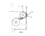
図7は、塊分離器の概略図である。図示のとおり、塊分離器120は、真空システムの吸引口112と供給リザーバ102の間に置かれる。分離器120は、空気、粉末状造形材料および吸引口112から入った混入異物を分離器120の内部周辺のほぼ環状の空気流路122に沿って流す。粉末状造形材料および空気は、分離スクリーン125を通り上方に流れ、分離器120を出て、供給リザーバ102に入る。大きすぎてスクリーン125を通過できない空気流路122中の混入異物は、分離器120の内部を循環し続ける。この循環運動は、異物の塊を破砕し損耗させるので、異物の一部は最終的にスクリーン125を通過する。分離器120の正面板127は取り外しでき、その取り外された箇所は溜まった屑を取り除くために利用する開口となる。
FIG. 7 is a schematic diagram of a lump separator. As shown, the
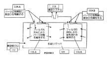
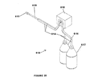
図8は、図3の真空システムのフィルタ・システムを示した概略図である。図示のとおり、真空システム110は供給リザーバ102内に配置された2つのフィルタ118−A、118−Bを備え、これらのフィルタにより、真空システム110によって捕集された微粒子(粉末状造形材料など)が室内に排出されないようにする。当業者には、それらのフィルタが粉末状造形材料で覆われる結果、フィルタを通過する空気流れが少なくなり、真空吸引口112に生じる圧力差が減少することは理解されるであろう。本フィルタ・システムを用いて、フィルタをクリーニングする。
FIG. 8 is a schematic diagram illustrating a filter system of the vacuum system of FIG. As shown, the
弁119−A、119−Bのシステムが、フィルタ排出口(真空口)に対する真空源の接続を遮断し、排出口(パージ口)に大気圧または大気圧に近い圧力で空気を流すことで、その空気流れの方向を逆にし、堆積している粉末を吹き飛ばして供給リザーバ102に落下させる。システムのもう一方のフィルタは供給リザーバ102内の空気流れおよび真空を維持する。このパージ工程が、各フィルタ部材につき順番に周期的に行われる。このようにして、ユーザの介入なしにフィルタをクリーニングでき、フィルタが自動的にクリーニングされる間、ユーザが真空システムの使用を止める必要がない。
The system of valves 119-A and 119-B cuts off the connection of the vacuum source to the filter discharge port (vacuum port) and allows air to flow through the discharge port (purge port) at atmospheric pressure or a pressure close to atmospheric pressure. The direction of the air flow is reversed, and the accumulated powder is blown off and dropped into the
(粉末供給)
粉末供給器100の基本的な機能は、プリント工程で必要とされるときに、計量された所定量の粉末状造形材料を3Dプリンタ・ユニット200に送ることである。
(Powder supply)
The basic function of the
図9は、粉末搬送機構の概略図である。供給リザーバ102は、詳しくは、約8.6立方フィート(0.24m3)の容積容量を有し、あるいはプリンタ・ユニット200の空間的制約内で可能な最大の実物モデルの1.75倍のものをプリントするのに充分な粉末状造形材料を収容可能なものである。粉末搬送機構120は、2条のコンベヤ・チェーンに取り付けられたスラット123を有するコンベヤ122を備えている。コンベヤは、電動モータによって駆動され、図中に矢印で示した方向に循環するように移動する。スラット123が、供給リザーバ102内の粉末状造形材料39を通過し、各スラット123が粉末状造形材料39の一部を造形面202の面よりも上方の地点に運ぶ。スラット123は駆動スプロケット125を通過するとき、投下点128で裏返しになり、粉末状造形材料が造形面202上の所定の位置に落下して、プリントされる実物モデルの表面上に広げられる。
FIG. 9 is a schematic view of the powder transport mechanism. The
図10は、投下点128におけるスラット123の詳細図である。
FIG. 10 is a detailed view of the
図9に示したシステムには、スラットが常に供給リザーバ102の周辺に沿って移動しているという別の利点がある。このようにすることで、スラット123の動きによって粉末が攪拌され、ブリッジおよび粉末が停滞した領域が形成されない。停滞領域は、停滞領域の粉末をコンベヤ・システム122によって供給リザーバから取り出すことができないため、避けることが望ましい。このような停滞領域は、停滞領域の粉末が供給用コンベヤの通常動作で使用されないため、粉末が無駄に利用されていることを意味している。
The system shown in FIG. 9 has the additional advantage that the slats are always moving along the periphery of the
大量の粉末を有するリザーバでは、コンベヤ122によってリザーバ内を引っ張られるスラット123に加わる力が、極めて大きくなる。スラットの構造を変更して、恒久的変形を生じることなく粉末状造形材料中を移動できるよう充分に強化できる。
In a reservoir having a large amount of powder, the force applied to the
図11は、簡単なスラットの実施形態の斜視図である。スラット123は脚部124を備えるとともに、2つのコンベヤ・チェーン122−A、122−Bに連結されている。このスラットは、最適な量の粉末状造形材料を搬送できるが、加わる荷重に耐えるには弱すぎる場合がある。脚部を補強して、剛性を高めることができる。
FIG. 11 is a perspective view of a simple slat embodiment. The
図12は、補強されたスラットの特定の実施形態を示した斜視図である。前記スラット123は追加の補強用部材126を備えており、スラットによって運ばれる粉末状造形材料の量を増やすことなく、この部材により強度が付加される。粉末は、スラット123の表面123−Sに載って運ばれる。この構成の別の利点は、粉末の抵抗によって生じるモーメントが、チェーン122−A、122−Bをプーリまたはスプロケットに巻き付けることである。逆向きのモーメントは、チェーンをプーリまたはスプロケットの周りを進行させず、むしろチェーンを妨害して停止させる傾向がある。
FIG. 12 is a perspective view illustrating a particular embodiment of a reinforced slat. The
(粉末の計量)
図13は、粉末状の造形材料を独立した計量システムに搬送する図9のコンベヤ・システムの概略図である。計量システム130は、3Dプリンタへの粉末状造形材料の流れを調節する。
(Weighing powder)
FIG. 13 is a schematic view of the conveyor system of FIG. 9 for conveying powdered build material to an independent metering system. The
図14A〜14Bは、図13の計量システムの概略図である。図14Aを参照すると、円筒体の計量ローラ133が、緊密に嵌合するチューブ134内に収納されている。計量ローラ133はその表面に軸方向の溝を4本有しており、これらの溝が計量凹部135−A、135−B、135−C、および135−Dを構成している。チューブ134は、作業位置に対応した入口スロット136および出口スロット137を有している。計量ローラ133がチューブ134内を回転するとき、粉末状造形材料が入口スロット136を通って計量凹部135−Aに入る。計量ローラ133が回転を続けると、粉末状造形材料は計量ローラ133とチューブ134の間に捕集され、出口スロット137まで運ばれ、出口スロット137から造形面202(図13)上に排出される。
14A-14B are schematic diagrams of the metering system of FIG. Referring to FIG. 14A, a
計量ローラ133とチューブ134との間の隙間は約0.015インチ(約0.4mm)であり、この寸法は、計量ローラ133が自由に回転できるよう充分大きく設定されているが、入口スロット136と出口スロット137の間の径方向の粉末の不要な流れを防止するよう充分狭く設定されている。計量凹部135はそれぞれ、約3立方インチ(約50cm3)の粉末状造形材料を保持し、この量は層厚さの所望の最小増分に必要な量に等しい。これにより、あらゆる所望の層厚さに相当する量の粉末状造形材料を、適切な数の計量凹部135が粉末状造形材料を捕集して搬送するまで、計量ローラ133を回転させることにより供給できる。
The clearance between the
さらに、図示した外輪攪拌器138により、計量ローラ133の上方の粉末状造形材料を攪拌してブリッジを破壊し、粉末状造形材料が計量凹部135に流れ込むようにする。
Further, the illustrated
払い羽根139が、計量ローラ133と反対の方向に回転する。粉末状造形材料を保持している計量凹部35が出口スロット137に入ると、払い羽根139が、計量凹部135から粉末状造形材料を払い出す。この方法により、材料が粘着性である場合やブリッジを形成しやすい場合でも、供給される粉末状造形材料の量の変動を防止できる。
The
図15は、供給リザーバ102の全体が造形面202の面より上方にあり、プリンタ・ユニット200’に一体化されている実施形態を示した概略図である。粉末が供給リザーバ102から造形面202の面上に計量して供給され、ガントリ210によって造形ボックス220全体にわたって広げられる。その後、粉末はプリントヘッドまたはプリントヘッド・アレイ205によってプリントされる。この実施形態では、計量システムを供給リザーバ102の底部に配置し、粉末材料を重力によって供給できる。別の実施形態では、粉末が凝集やブリッジを生じやすいタイプのものである場合、計量システムを供給リザーバ102の底部に配置し、リザーバに外輪や加振機構を備えることにより、粉末の計量システムへの流れを保証できる。
FIG. 15 is a schematic diagram illustrating an embodiment in which the
粉末を造形チャンバの片側に供給し、その後ローラで造形チャンバを横切るように広げることができるが、供給リザーバを、造形チャンバを横切って移動できるガントリ210に取り付けることもできる。ガントリが移動するとき、粉末を供給リザーバから連続的に計量して取り出し、造形チャンバ220に直接堆積させることができる。このような方法の1つの実施形態においては、ローラやドクター・ブレードを利用して、供給リザーバが通過した後に、堆積した粉末材料の表面を平滑にし、高さを揃えることができる。
Although powder can be fed to one side of the build chamber and then spread with a roller across the build chamber, the supply reservoir can also be attached to a
(プリントヘッド)
プリントヘッドのクリーニング
3Dプリント・ユニット200はインクジェット・プリントヘッド・アレイを用いて、粉末状造形材料の連続する層に結合剤材料を選択的に供給し、造形材料を選択的に硬化させて3D実物モデルを形成する。この方法は、本明細書に引用した、例えばBredtらの米国特許第5、902、441号に詳細が開示されている。優れたインクジェット式プリント装置の1つの態様は、プリントヘッドの表面を清浄に保つ方法である。3Dプリント環境においてプリントヘッドを清浄に保つことは、プリントヘッドの表面近傍に粉末状造形材料が高濃度で飛散しているため、特に要求されていることである。大部分のインクジェット・プリンタでは、プリントヘッドの表面をスキージ状の拭き取り部材で定期的に拭っている。
(Print head)
Printhead Cleaning The
図16A〜16Bは、特定のクリーニング装置300の概略図である。図示のとおり、拭き取り部材305は、プリントヘッド205が拭き取り部材305の上方を図中の矢印で示した左方向に移動するとき、プリントヘッド205の表面を拭うように位置している。プリントヘッド205が拭き取り部材305上を通過するとき、汚染物質がプリントヘッド205の表面から拭き取り部材305に移される。この方法は、汚染物質が拭き取り部材上に堆積されない限り機能する。
16A-16B are schematic views of a
図示のとおり、拭き取り部材305はベルト302上に取り付けられている。ベルト302は、モータ306によって回転するプーリ304−A、304−B上を走行する。拭き取り部材305は所定の位置に静止しており、プリントヘッド205の表面を拭う。モータ306を動作させると、図16Bに示すとおり、拭き取り部材305が拭き取りブロック309のクリーニング面308に渡って図中の矢印に示す方向に引っ張られ、堆積していた汚染物質が拭き取りブロック309に移される。拭き取りブロック309は、拭き取り面を清浄に保つため定期的に交換される。
As shown, the wiping
図17は、クリーニング装置を有するクリーニングステーションの別の特定の実施形態を示した概略図である。このクリーニングステーション300’では、クリーニングのため、拭き取り部材305’を液面308’まで洗浄液309’で満たされた凹形のクリーニングステーション300’に引き込むことができる。拭き取り部材305’は引き込まれたとき洗浄液309’に完全に浸かる。攪拌器307は、様々な手段、例えば超音波振動、洗浄液の急速な循環、または気泡の注入によって洗浄液309’を攪拌できる。
FIG. 17 is a schematic diagram illustrating another specific embodiment of a cleaning station having a cleaning device. In the cleaning
プリントヘッドの故障検出
プリントヘッドの耐用年数は、使用状況およびその他の制御し得ない変動要素によって変わってくる。プリントヘッドが部分的に故障し、一部のジェットが停止し、その他は正常に噴射することがある。また、プリントヘッド全体が故障し、全てのジェットが機能しなくなることもある。プリントヘッドの故障理由およびプリントヘッドの寿命は大きく変動するため、およびプリントヘッドの故障は所望の実物モデルを作るための3Dプリンタの故障を引き起こすため、プリントヘッドの状態を検出し、プリントヘッドのジェットの一部、大部分、あるいは全てが射出しているのかを検知できることは有用である。
Printhead failure detection The life of a printhead depends on usage and other uncontrollable variables. The printhead may partially fail, some jets may stop, and others may fire normally. Also, the entire printhead can fail and all jets can fail. Because printhead failure reasons and printhead lifetimes vary widely, and printhead failures cause 3D printer failures to produce the desired real model, printhead status is detected and printhead jets are detected. It is useful to be able to detect whether part, most, or all of the fire is being ejected.
図18は、プリントヘッドの状態を監視するための液滴検知器を示した概略図である。プリントヘッド205が液滴検知器400の上方の所定の位置に移動した後、プリントヘッド205のジェットがそれぞれ独立に、ジェットが通常通り噴射していることを検知器が確実に検出するのに充分な回数の噴射を行う。別の実施形態では、一群のジェットを同時に噴射させ、検知器は各群の内のジェットがいくつ正常に噴射しているのかを、どのジェットが故障しているかを特定することなく検出する。この方法は、複数のジェットを同時に試験できるため、時間を要さない。
FIG. 18 is a schematic diagram showing a droplet detector for monitoring the condition of the print head. After the
特定の液滴検知器400は、光学的手段によって動作する。例えば、発光器は結合剤が不透明となる周波数の光(例えば赤外線)を放射できる。プリントヘッドから噴射された液滴が光線を横切ったとき、光線が遮断される。この遮断が検出できないということは、ジェットが故障していることを示す。検出用の光線が充分細い場合、照準のずれているジェットを検出することもできる。
別の特定の液滴検知器400は、マイクロホンや圧電検知器に取り付けた膜上への液滴の衝突を検出することによって機能する。
Another
プリントヘッド故障の補償方法
各プリントヘッドが正しく機能しているか否かが検出可能になることで、3Dプリンタの種々の動作モードが設計可能になる。最も単純な動作モードでは、故障が検出されるとすぐにプリント・ジョブを中断する。ユーザは、故障したプリントヘッドを短時間のうちに交換するか、またはジョブを中止する。あるいは、いかなる場合もプリント・ジョブを中止するようにできる。これにより、時間を節約でき、消費される粉末の量を少なくできる。液滴検知器なしでは、プリントヘッドが部分的に故障した場合、あるいはプリンタの複数のプリントヘッドの内の1つが完全にまたは部分的に故障した場合、完成した部分(実物モデル)が十分な品質を有していないにもかかわらず、多量の粉末がプリントされてしまう。欠陥が検出されたときにプリント・ジョブを中止することで、ユーザは、欠陥が検出されなかった場合に無駄になる結合剤および粉末の費用を節約することができる。
Compensation Method for Print Head Failure Since it becomes possible to detect whether each print head is functioning correctly, various operation modes of the 3D printer can be designed. In the simplest mode of operation, the print job is interrupted as soon as a fault is detected. The user replaces the failed print head in a short time or cancels the job. Alternatively, the print job can be canceled in any case. This saves time and reduces the amount of powder consumed. Without a drop detector, if the printhead fails partially or if one of the printheads of the printer completely or partially fails, the finished part (actual model) is of sufficient quality In spite of not having a large amount of powder, a large amount of powder is printed. By canceling the print job when a defect is detected, the user can save the cost of binder and powder that is wasted if no defect was detected.
別の動作モードでは、一部のジェットが機能していないことが検出されたが、他のジェットは機能している場合(例えば、複数プリントヘッドのアレイのうちの1つが故障した場合)、プリント工程を変更して、部分の各領域をプリントヘッドが複数回通過するようにする。X軸(プリントヘッド・アレイ)を、プリントヘッドの通過経路のY軸方向における通常の間隔に対して、その1/nだけ前進させることにより、各領域がn個の異なるジェットでプリントされることになる。各プリントヘッドが通過する度にプリントされる結合剤の量は、通常の量の1/nに減らされる。nの選択は、部分の強度の弱い領域(n−1個の機能しているジェットでプリントされた領域)が、満足できる部分を提供するのに十分な強度となるように行われる。 In another mode of operation, if some jets are detected to be non-functional but other jets are functioning (eg, if one of the array of multiple printheads fails), the print The process is changed so that the print head passes multiple times through each area of the part. Each area is printed with n different jets by advancing the X axis (printhead array) by 1 / n of the normal spacing in the Y axis direction of the printhead path. become. The amount of binder printed with each printhead is reduced to 1 / n of the normal amount. The choice of n is made so that the area of weakness of the part (area printed with n-1 functioning jets) is strong enough to provide a satisfactory part.
さらに別の動作モードでは、複数プリントヘッド・アレイの一端あるいは他端にあるプリントヘッドが故障した場合に、アレイの幅を(n−1個(nは通常時のプリントヘッドの数)のプリントヘッドを有しているため)再設定し、プリント・ジョブを完遂することができる。 In yet another mode of operation, if a print head at one or the other end of a multiple print head array fails, the array width (n-1 (n is the number of normal print heads)) is the print head. To complete the print job.
4つ以上のプリントヘッドを有し、少なくとも1つのプリントヘッドに原色(シアン、マゼンタ、および黄色)のうちの1つの着色剤を有する結合剤が供給されるカラー3Dプリンタでは、別の動作モードが可能である。詳細には、検知器がプリントヘッドの1つが故障していることを検出した場合、前述の重複プリント・モードを使用し、単色モードで(または、速度を向上させるため、故障したプリントヘッドの色以外の全ての色を使用するモードで)プリント・ジョブを完成することができる。この方法によれば、ユーザは色付き部分ではないが品質の良い部分を得ることができ、または別の場合には、設計どおりの色ではないが色付きの部分を得ることができる。 In a color 3D printer having four or more printheads, where at least one printhead is fed with a binder having one of the primary colors (cyan, magenta, and yellow), another mode of operation is available. Is possible. Specifically, if the detector detects that one of the printheads is faulty, it uses the above-mentioned duplicate print mode and uses the color of the faulty printhead in single color mode (or to improve speed). A print job can be completed (in a mode that uses all colors except). According to this method, the user can obtain a high-quality portion that is not a colored portion, or, in another case, can obtain a colored portion that is not a color as designed.
(後処理)
粉末の除去
実物モデルがプリントされ、例えば図3に示した真空システム110を用いることによってプリントされなかった粉末状造形材料の大部分が除かれると、次に、以前残留しているプリントされなかった粉末状造形材料の除去が望まれる。プリントされなかった粉末状造形材料とプリントされた実物モデルとは粘着性であるため、真空システム110のみを用いてプリントされなかった全ての粉末状造形材料を取り除くことは一般に不可能である。残留している粉末状造形材料をブラシで払うことができるが、これは実物モデルの形状によっては時間がかかり、または不可能な作業であり、繊細な実物モデルを破損することがある。実物モデルから結合していない粉末状造形材料を除去する特定の方法は、圧縮空気で吹き飛ばす方法である。ただし、この方法は、粉末状造形材料を雲状の飛散物としてしまうため、多くの問題を引き起こす。
(Post-processing)
Powder Removal Once the real model has been printed, and most of the powdered build material that has not been printed, for example, by using the
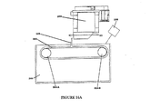
図19は、特定の粉末除去ブースを示した概略図である。実物モデルに向けた圧縮空気の噴射によって生じる粉末状造形材料の雲状の飛散物を封入し、この飛散物を誘導する、空気の流れが粉末除去ブース500内で作られる。開口503により、粉末除去ブース500の内部空間にアクセスすることができる。粉末除去される実物モデルは、開口503内の載置面504上に置かれる。窓505は飛散した粉末状造形材料の封入を助けるため閉じることができ、またこれを開いて、大型の実物モデルを粉末除去ブース500内に置くことができる。ブースの動作によって生じる騒音を減衰させるため、囲い板506がブロワ−510を覆っている。
FIG. 19 is a schematic diagram illustrating a specific powder removal booth. An air flow is created in the
図20は、図19の粉末除去ブースの破断図である。電動モータ515で駆動されるブロワ−510により、空気が粉末除去ブース500内を循環する。図中の矢印に示すように、空気はブロワ−510から出て分流器530に入り、そこで2つの別々の流れに分割され、第1の空気流れがエア・カーテン・ダクト518によって導かれるエア・カーテン流れ517、第2の空気流れが粉末除去流れ519となる。両方の流れは、回転台520上に支持された実物モデル3の近傍で再度合流し、粉末状造形材料を一緒に運ぶ。その後、合流した空気流れは支持面522の開口を通過し、フィルタ524を通過する。濾過された空気流れがフィルタ524から出て清浄空気プレナム526に入り、そこからブロワ−510の入口に入って空気流れの循環が終了する。
20 is a cutaway view of the powder removal booth of FIG. Air is circulated in the
粉末状造形材料を含んだ空気がフィルタ524を通過するとき、粉末状造形材料がフィルタ524の表面に積もり、最終的には空気流れを妨げてシステムの効率を低下させる。フィルタ524を詰まっていない状態に保つため、清浄空気プレナム526からフィルタ524の内部に、空気パルス(バックパルス)が定期的に導入される。これにより、フィルタ524を通過する空気流れを一時的に逆流させて、堆積した粉末状造形材料をフィルタ524の表面から分離させ、引出し528内に落下させる。粉末収集引出し528は、空にするために取り外すことができる。
As the air containing the powdered build material passes through the
1つの目的は、飛散した粉末状造形材料が粉末除去ブース500の開口503(図19)から漏れ出て、周囲環境を汚染するのを防止することにある。特に、圧縮空気の高速噴射が実物モデル3に向けられたとき、実物モデルから反射した圧縮空気のかなりの部分が、粉末除去ブース500からユーザ方向に流れ出る。この飛散した粉末状造形材料の漏出を防ぐため、第1のエア・カーテン流れ517(図20)が窓505(図19)の表面に沿って垂直下方に導かれるため、外に向かう圧縮空気流れを効果的に捉えてその方向を変える。
One purpose is to prevent the scattered powdery modeling material from leaking from the opening 503 (FIG. 19) of the
ブロワ−の排気を全てブース500の表面に沿って流れるように誘導すると、極めて効果的なエア・カーテンを作り出すことができる。ただし、この場合、ブース内の空気の大部分が停滞し、粉末除去ブース500の内部空間に空気がゆるやかに循環している領域が形成される。粉末状造形材料が実物モデル3から吹き払われたとき、ゆるやかに循環する空気は浮遊する粉末粒子によって直ちに不透明状態になる。この不透明な粉末の雲状物は直ぐには消散せず、ユーザの生産性を低下させる。図20に示した第2の粉末除去流れ519は、この問題に対処するものであり、ブース500全体に下方に向かう空気流れを作り出し、したがって空気流れが停滞することなく、発生した粉末の雲状物が急速に消散する。
Directing all blower exhaust to flow along the surface of the
第1のエア・カーテン流れ517と第2の空気除去流れ519との間の最適なバランスは、除去される粉末状造形材料の特性および粉末を除去される実物モデルの形状によって、幾分変化する。この理由から、分流器530は調整可能である。
The optimal balance between the first
図21は、図20の分流器の概略図である。ユーザ操作のレバー532により、機械的リンク533が分流器翼534を転心535を中心として図中の矢印に示すように上下に回転させる。分流器翼534の端部536が下方に動いたとき、エア・カーテン・ダクト518を下方に流れる第1のエア・カーテン流れ517が、全空気流れの大部分を占める。分流器翼534の端部536が上方に動いたとき、排気プレナム538に流入する第2の空気クリーニング流れ519が、全空気流れの大部分を吸引する。
FIG. 21 is a schematic diagram of the shunt of FIG. By means of a
図22は、図15のプリンタ・ユニット200’に組み込まれた粉末除去ブースの概略図である。図示のとおり、ブロワ−510が粉末除去ブース500に結合されている。空気流れは、ブース500の前面開口を横切って下方に流れ、粉末を運び、フィルタ(図示せず)を通過してブロワ−510の入口に戻る。この構成においては、粉末の除去とプリントとが同一の装置で行われる。
FIG. 22 is a schematic view of a powder removal booth incorporated in the printer unit 200 'of FIG. As shown, a
粉末除去ブース500がプリンタ・ユニット200’から分離している場合には、運搬車を利用して、大きなあるいは重い実物モデルを粉末除去ブース500に移動させることができる。実物モデルは、プリント工程に先立って3Dプリンタの造形テーブル上に置かれたパレット上でプリントされる。プリントが完了したとき、運搬車がプリント・ユニット200’の近傍に置かれ、両者は一式の搬送レールで橋渡しされる。これらのレールは多数のローラを有し、これらのローラによりプリント済みの実物モデルを載せたパレットを、運搬車上に滑らかに摺動させることができる。その後、運搬車は粉末除去ブース500の近傍に置かれ、搬送レールを用いて、プリント済みの実物モデルを載せたパレットを粉末除去ブース500内に摺動する。
When the
含浸
3Dプリント工程によって作成された実物モデルは多孔性であり、様々な樹脂で含浸することにより、その特性を変えることができる。樹脂は、浸漬、ブラシ塗布、および注入を含む様々な方法で実物モデルに含浸することができる。これら手法のそれぞれは、時間を要するか、樹脂を浪費するか、あるいはその両者である。本発明では、噴霧工程によって樹脂を実物モデルに含浸する。3Dプリントモデルに使用される含浸剤の多くは接着剤である。接着剤の噴霧は多くの問題を引き起こす。第1に、噴霧工程の間に(例えば過剰な噴霧、または微粒化噴霧の跳ね返りにより)発生する蒸気を封じ込める必要がある。蒸気を封じ込めない場合、ユーザ、ユーザの衣服、あるいはその他の物体に付着する。特定の含浸剤では、蒸気が健康上または環境上の危険を引き起こす可能性がある。接着剤の噴霧に伴う別の問題は、噴霧装置が接着剤で覆われ、使用のたびに完全にクリーニングしなければならないことである。これは時間を要する作業であり、接着剤の溶媒が有害である場合、健康上または環境上の問題を引き起こしかねない。
Impregnation The real model created by the 3D printing process is porous and its properties can be altered by impregnation with various resins. The resin can be impregnated into the real model in a variety of ways including dipping, brushing, and pouring. Each of these approaches is time consuming, wastes resin, or both. In the present invention, a real model is impregnated with a resin by a spraying process. Many of the impregnating agents used in 3D print models are adhesives. Adhesive spraying causes a number of problems. First, it is necessary to contain the vapor generated during the spraying process (eg, due to excessive spraying or bounce of atomized spray). If it cannot contain the vapor, it will adhere to the user, the user's clothing, or other objects. With certain impregnating agents, steam can pose a health or environmental hazard. Another problem with adhesive spraying is that the spraying device is covered with adhesive and must be thoroughly cleaned with each use. This is a time consuming task and can cause health or environmental problems if the solvent of the adhesive is harmful.
図23は、図19の粉末除去ブースのライナを示した概略図である。ライナ560は、ブース500を含浸剤の過剰な噴霧から保護する。ライナ560はプレ・フィルタ562を備え、そのプレ・フィルタ562により、飛散した接着剤の液滴を捕集して、飛散した接着剤の液滴が粉末除去ブース500内のフィルタ524(図20)を覆うことを防止している。粉末除去ブース500内で実物モデルの粉末除去が終了したとき、ユーザは、好ましくは段ボール紙で作られるライナ560を粉末除去ブース500内で開き、実物モデルに含浸剤を噴霧する。あるいは、ライナを利用して、通気孔のフードまたはダクトの無い排気フードを保護することもできる。
FIG. 23 is a schematic view showing the liner of the powder removal booth of FIG.
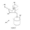
図24は、噴霧によって樹脂含浸剤を塗布するシステムを示した概略図である。システム600において、樹脂は蠕動ポンプ603によって含浸剤貯蔵容器602から使い捨ての配管604を通して送られ、使い捨ての噴霧ノズル605を通って噴射される。使い捨ての構成部品および接着剤で濡れることのない蠕動ポンプを備えるシステムを使用することにより、安価でかつユーザが使い易い接着剤噴霧システムを形成できる。クリーニングは、配管および噴霧ノズルを廃棄することによる。
FIG. 24 is a schematic view showing a system for applying a resin impregnating agent by spraying. In the
図25は、2成分からなる含浸剤を噴霧するシステムの概略図である。2成分の含浸剤とは、2つの成分が結合されたときに硬化する含浸剤である。システム610において、樹脂成分は2ヘッド蠕動ポンプ618によって、含浸剤リザーバ616、617から使い捨ての配管614を通して送られる。2つの樹脂成分は可動部のない静的混合器619で混合され、混合物が使い捨ての噴霧ノズル615を通って噴射される。2成分の混合比は、各配管に適切な径を用いることにより保たれる。特に、成分の比が1対1のとき両方の配管が同一径である必要がある。
FIG. 25 is a schematic view of a system for spraying a two-component impregnating agent. A two-component impregnating agent is an impregnating agent that cures when two components are combined. In
(粉末の制御)
ピストンのシール
造形および供給用のピストンをシールすることにより、未結合の粉末がピストン・アセンブリの側面を通って漏出し、アセンブリの下方に落下して、アセンブリの下方に位置する機構を汚染し、損傷を与えないようにすることは重要である。
(Powder control)
Sealing the piston By sealing the piston for shaping and feeding, unbound powder leaks through the side of the piston assembly and falls below the assembly, contaminating the mechanism located below the assembly, It is important to avoid damage.
図26は、密封されたピストンの正面断面図である。図示のとおり、通電されたチューブ712はフェルト714を外方に押し、ピストン・ボックス710の内表面に押し付ける。チューブ712の上部および側部は、ピストン・アセンブリ718のピストン・アセンブリ・プレート715で囲まれている。フェルト714はチューブ・シール712とピストン・ボックス710の側面との間に置かれて、シールを形成する。
FIG. 26 is a front cross-sectional view of a sealed piston. As shown, the energized
粉末ガター
3Dプリントは、粉末を供給する供給ボックスおよび部分の製作が行われる造形ボックスを含む。3Dプリント工程において、粉末は、真空によって除去されるまで、これら粉末ボックスの周囲の表面(デッキと呼ばれる)上に積もる。プリント工程の間に拡散する粉末は有害物となり、特にプリントヘッドや作業台のような、3Dプリンタの各部に性能上の問題を発生させる可能性がある。機能上の理由で、プリントヘッドおよび作業台は、粉末ボックスの上縁の面近くに位置する必要がある。デッキがこれら上縁と同一面上にあると、デッキに積もった粉末は、これら損傷を受け易い構成部品に近づく可能性がある。したがって、より望ましい実施形態では、デッキの面を粉末ボックスの上縁よりも下方に下げ、粉末が落下するガターを形成する。
The powder gutter 3D print includes a supply box for supplying powder and a shaping box in which the production of the part takes place. In the 3D printing process, the powder accumulates on the surrounding surfaces (called decks) of these powder boxes until they are removed by vacuum. Powder that diffuses during the printing process can be harmful and can cause performance problems, especially in various parts of the 3D printer, such as the print head and workbench. For functional reasons, the print head and workbench need to be located near the face of the upper edge of the powder box. If the deck is flush with these top edges, the powder that accumulates on the deck can approach these vulnerable components. Thus, in a more preferred embodiment, the deck face is lowered below the upper edge of the powder box to form a gutter where the powder falls.
図27は、粉末ボックスの概略断面図である。プリンタのデッキ802が、粉末ボックスの上縁804Tよりも下方に下げられている。この構成により、拡散した粉末を捕集できるガター805が形成される。
FIG. 27 is a schematic cross-sectional view of a powder box.
プラウ
プラウにより、粉末が拡散してピストン・ボックスの側方から漏出するのを防止できる。1つの方法は、ばねでガントリに固定されるプラウを用い、このプラウにより3Dプリンタの上部デッキに下方向の力が作用するようにする。特定のプリンタは小型の磁石を内蔵しているプラウを備え、力を作用させる。このプラウは、ばねを備えたプラウに比べて組立ておよび分解が容易である。別の改良はプラウの位置に関する。
Plow Plow prevents powder from diffusing and leaking from the side of the piston box. One method uses a plow that is fixed to the gantry with a spring that causes a downward force to act on the upper deck of the 3D printer. Certain printers have a plow with a small magnet built in to exert a force. This plow is easier to assemble and disassemble than a plow with a spring. Another improvement relates to the position of the plow.
図28は、磁石付きプラウの構成を示した断面図である。プラウ801−1および801−2は、プリンタのガントリ210’に、粉末ボックスの壁面804−1および804−2に垂直な方向には自由に動くが、他のすべての方向についてはガントリ210’に固定されるよう取り付けられている。壁面804−1および804−2は、鋼などの軟磁性材料で製作されている。プラウにはそれぞれ磁石812−1および812−2が埋め込まれており、これらの磁石が、それぞれの壁面に対し充分な力で作用してプラウが壁面に密着するように保ち、粉末を広げる動作の間に粉末39がデッキ802上に溢れ出すのを防ぐための防壁として作用する。
FIG. 28 is a cross-sectional view showing a configuration of a plow with a magnet. The plows 801-1 and 801-2 move freely in the direction perpendicular to the powder box walls 804-1 and 804-2 to the printer gantry 210 ', but to the gantry 210' in all other directions. It is attached to be fixed. The wall surfaces 804-1 and 804-2 are made of a soft magnetic material such as steel. Magnets 812-1 and 812-2 are embedded in the plows, respectively, and these magnets act on each wall surface with sufficient force to keep the plow in close contact with the wall surface and spread the powder. It acts as a barrier to prevent the
(結合剤の供給)
重力作用による結合剤供給
3Dプリントは一般に、2Dプリント用に設計された市販のプリントヘッドを利用する。プリントされる粉末に適合する特殊な結合剤材料が、プリントヘッドによって吐出される通常のインクに代わって用いられる。一般的な3Dプリントされる部分(実物モデル)は、プリントヘッド内に収容できる結合剤よりもはるかに多くの結合剤を必要とし、かつ部分の製作中にプリントヘッドを交換することは実際上不可能なため、プリンタの動作中、プリントヘッドに結合剤を連続的に補給する必要がある。これは一般に、可動のプリントヘッドと静止結合剤供給源との間に配管接続を行うことにより実現される。
(Binder supply)
Binder Supply by Gravity Action 3D printing generally utilizes a commercial printhead designed for 2D printing. A special binder material that is compatible with the powder to be printed is used in place of the normal ink ejected by the printhead. A typical 3D printed part (actual model) requires much more binder than can be accommodated in the printhead, and it is practically impossible to replace the printhead during part manufacture. Because of this, it is necessary to continuously refill the print head with binder during printer operation. This is generally accomplished by making a piping connection between the movable printhead and the stationary binder supply.
プリントヘッドが適正に動作するには、インクジェット・チャネルに通じる入口におけるプリントヘッド内の圧力は、通常は水頭−3〜−6インチ(−76〜−152mm)の圧力に相当する小さな負圧に保たれなければならない。従来技術の1つの方法では、自由面がプリントヘッドの出口よりも約4インチ(約100mm)下方のレベルに保たれたインク供給源を使用している。プリントヘッドは、プリントヘッド供給配管圧力が陽圧の広い範囲で変動しても必要な内部負圧を維持する内臓式圧力調節器を備えた状態で入手可能である。一般的に、結合剤供給配管の供給端において結合剤に充分な圧力を加えることにより、結合剤が適切な流量で配管を流れ、プリントヘッドが常に満たされた状態に保つ必要がある。必要な圧力は、主として、流れを制限する供給配管の特性、および供給源のプリントヘッドに対する相対的高さに依存して決まる。従来技術の1つの方法では、プリントヘッドへの入口における供給圧力を保つポンプを使用している。この方法は複雑であるため、高価であり信頼性を低下させる可能性がある。 For proper operation of the printhead, the pressure in the printhead at the inlet leading to the inkjet channel is usually kept at a small negative pressure corresponding to a pressure of -3 to -6 inches (-76 to -152 mm). I have to lean. One prior art method uses an ink supply whose free surface is maintained at a level about 4 inches below the printhead exit. The print head is available with a built-in pressure regulator that maintains the required internal negative pressure even if the print head supply piping pressure varies over a wide range of positive pressures. In general, by applying sufficient pressure to the binder at the supply end of the binder supply piping, it is necessary for the binder to flow through the piping at an appropriate flow rate and keep the print head always filled. The required pressure depends primarily on the characteristics of the supply tubing that restricts the flow and the relative height of the source to the printhead. One prior art method uses a pump that maintains the supply pressure at the inlet to the printhead. Since this method is complex, it is expensive and may reduce reliability.
図29は、重力作用送りによる結合剤供給を示した概略図である。図示のとおり、固定された結合剤供給源1002が、1本の配管1004によりプリントヘッド205に接続されている。結合剤供給源1002をプリントヘッド205よりも上方の充分高い位置に置き、配管1004を通したプリントヘッドへの供給を維持する。詳細には、結合剤の自由表面は、プリントヘッド下面よりも3.5〜5インチ(90〜130mm)上方に位置する。この高さにより、内径1/16インチ(1.6mm)および長さ約6フィート(約1.8m)の1本の配管を通じて、必要とされる8グラム/分を超える流量で結合剤をプリントヘッドに供給するのに充分な圧力を与える。必要な流量を得るため、供給源の高さと配管の寸法について他の組み合わせも選択できることは、当業者であれば理解できるであろう。
FIG. 29 is a schematic diagram showing the binder supply by gravity action feed. As shown, a fixed binder supply source 1002 is connected to the
本発明の3次元プリンタを、いくつかの特定の実施形態により詳細に図示し、説明してきたが、添付の特許請求項に包含される本発明の範囲を逸脱することなく、形状および細部の各種の変更が実行可能であることは、当業者であれば理解されるであろう。 While the three-dimensional printer of the present invention has been illustrated and described in detail in accordance with certain specific embodiments, various shapes and details can be obtained without departing from the scope of the invention as encompassed by the appended claims. Those skilled in the art will appreciate that these modifications are feasible.
1 ディジタル・モデル
3 半完成の実物モデル
5 完成した実物モデル
10 コンピュータ
15 アプリケーション・プログラム
30 3Dプリンタ・アセンブリ
32 制御電子機器
35 インクジェット・プリントヘッド・アレイ
37 液体結合剤
39 粉末状造形材料
50 後処理システム
52 搬送システム
54 乾燥システム
56 粉末除去システム
58 含浸システム
1
DESCRIPTION OF
Claims (5)
前記供給リザーバに配管された真空吸引口を有する真空システムと、
前記供給リザーバからの造形材料の漸増する層を収容する造形チャンバと、
前記供給リザーバから移送されるが、前記造形チャンバに収容されなかった過剰な量の造形材料を収容するオーバーフロー・キャビティと、
前記真空システムにより形成された空気流れから、造形材料を濾過により除去する、前記真空システム内に配置された複数のフィルタと、
前記フィルタの各々に順次に逆向きの空気流れを導く弁システムを有し、前記逆向きの空気流れによって堆積した粉末を取り除くことにより、前記フィルタをクリーニングするクリーニング機構と、
を備え、
前記複数のフィルタのそれぞれが、前記真空システムにフィルタを接続する真空口およびフィルタに空気を導入するパージ口を有しており、
前記弁システムは、前記複数のフィルタのうちの一部のフィルタのパージ口を閉鎖し、真空口を開放して該フィルタの空気流れを維持する時に、残りのフィルタのパージ口を開放し、真空口を閉鎖して該フィルタに前記逆向きの空気流れを導く、3次元物体製作装置。A supply reservoir for storing a modeling material used to produce a three-dimensional object;
A vacuum system having a vacuum suction port piped to the supply reservoir;
A build chamber containing an incremental layer of build material from the supply reservoir;
An overflow cavity that contains an excess amount of build material that was transferred from the supply reservoir but was not contained in the build chamber;
A plurality of filters disposed within the vacuum system for removing build material by filtration from an air flow formed by the vacuum system;
A cleaning system for cleaning the filter by removing a powder deposited by the reverse air flow, having a valve system for sequentially directing the reverse air flow to each of the filters ;
Equipped with a,
Each of the plurality of filters has a vacuum port for connecting a filter to the vacuum system and a purge port for introducing air into the filter;
When the valve system closes the purge ports of some of the plurality of filters and opens the vacuum ports to maintain the air flow of the filters, the remaining filter purge ports are opened, A three-dimensional object manufacturing apparatus that closes the mouth and guides the air flow in the reverse direction to the filter .
前記供給リザーバに配管接続された真空吸引口を有する真空システムを動作させ、
造形チャンバ内に、前記供給リザーバからの前記造形材料の漸増する層を収容し、
オーバーフロー・キャビティ内に、前記供給リザーバから移送されるが、前記造形チャンバに収容されなかった過剰な量の造形材料を収容し、
前記真空システム内に複数のフィルタを配置し、
前記フィルタの各々に順次に逆向きの空気流れを導く弁システムを設けて、堆積した粉末を取り除くことにより、前記フィルタをクリーニングする、
ことを含み、さらに、
前記複数のフィルタのそれぞれに、前記真空システムにフィルタを接続する真空口およびフィルタに空気を導入するパージ口を設け、
前記弁システムを操作して、前記複数のフィルタのうちの一部のフィルタのパージ口を閉鎖し、真空口を開放して該フィルタの空気流れを維持する時に、残りのフィルタのパージ口を開放し、真空口を閉鎖して該フィルタに前記逆向きの空気流れを導く、
ことを含む3次元物体製作方法。In the supply reservoir, store the building material used to make the object,
Operating a vacuum system having a vacuum suction port connected to the supply reservoir;
Contains a progressive layer of the build material from the supply reservoir in a build chamber;
Contains an excess amount of build material transferred from the supply reservoir but not contained in the build chamber into an overflow cavity;
Placing a plurality of filters in the vacuum system;
Providing a valve system for directing a reverse air flow to each of the filters in sequence to clean the filters by removing accumulated powder ;
Look at including that, further,
Each of the plurality of filters is provided with a vacuum port for connecting a filter to the vacuum system and a purge port for introducing air into the filter,
When the valve system is operated to close the purge ports of some of the plurality of filters, and the vacuum ports are opened to maintain the air flow of the filters, the remaining filter purge ports are opened. Closing the vacuum port and directing the reverse air flow to the filter,
3-dimensional object fabrication method comprising.
前記貯蔵手段に配管接続された真空吸引口を有する真空システムを動作させる手段と、
前記貯蔵手段からの造形材料の漸増する層を造形チャンバ内に収容する手段と、
前記貯蔵手段から移送されるが、前記造形チャンバに収容されなかった過剰な量の造形材料を収容する手段と、
前記真空システム内に配置されて、前記真空システムによって形成された空気流れから造形材料を濾過により除去する複数の濾過手段と、
前記濾過手段の各々に順次に逆向きの空気流れを導く弁システムを有し、前記逆向きの空気流れによって堆積した粉末を取り除くことにより、前記濾過手段をクリーニングする手段と、
を備え、
前記複数の濾過手段のそれぞれが、前記真空システムに濾過手段を接続する真空口および濾過手段に空気を導入するパージ口を有しており、
前記弁システムは、前記複数の濾過手段のうちの一部の濾過手段のパージ口を閉鎖し、真空口を開放して該濾過手段の空気流れを維持する時に、残りの濾過手段のパージ口を開放し、真空口を閉鎖して該濾過手段に前記逆向きの空気流れを導く、3次元物体製作装置。Means for storing the modeling material used to produce the object;
Means for operating a vacuum system having a vacuum suction port connected to the storage means;
Means for accommodating an incremental layer of build material from the storage means in a build chamber;
Means for accommodating an excess amount of modeling material that was transferred from the storage means but was not accommodated in the modeling chamber;
A plurality of filtering means disposed within the vacuum system to remove the build material by filtration from the air stream formed by the vacuum system;
Means for cleaning the filtration means by removing the powder deposited by the reverse air flow, having a valve system for directing a reverse air flow in sequence to each of the filtration means ;
Equipped with a,
Each of the plurality of filtration means has a vacuum port for connecting the filtration means to the vacuum system and a purge port for introducing air into the filtration means,
When the valve system closes the purge ports of some of the plurality of filtration means and opens the vacuum ports to maintain the air flow of the filtration means, the purge ports of the remaining filtration means are opened. A three-dimensional object manufacturing apparatus that opens, closes a vacuum port, and guides the air flow in the reverse direction to the filtering means .
Applications Claiming Priority (2)
| Application Number | Priority Date | Filing Date | Title |
|---|---|---|---|
| US32531001P | 2001-09-27 | 2001-09-27 | |
| PCT/US2002/031102 WO2003026876A2 (en) | 2001-09-27 | 2002-09-27 | Three-dimensional printer |
Publications (3)
| Publication Number | Publication Date |
|---|---|
| JP2005503939A JP2005503939A (en) | 2005-02-10 |
| JP2005503939A5 JP2005503939A5 (en) | 2006-01-05 |
| JP4611629B2 true JP4611629B2 (en) | 2011-01-12 |
Family
ID=23267354
Family Applications (1)
| Application Number | Title | Priority Date | Filing Date |
|---|---|---|---|
| JP2003530492A Expired - Lifetime JP4611629B2 (en) | 2001-09-27 | 2002-09-27 | 3D printer |
Country Status (6)
| Country | Link |
|---|---|
| EP (1) | EP1429911B8 (en) |
| JP (1) | JP4611629B2 (en) |
| AT (1) | ATE549150T1 (en) |
| CA (1) | CA2460447A1 (en) |
| ES (1) | ES2387299T3 (en) |
| WO (1) | WO2003026876A2 (en) |
Cited By (1)
| Publication number | Priority date | Publication date | Assignee | Title |
|---|---|---|---|---|
| EP3028840A1 (en) | 2014-12-01 | 2016-06-08 | Ricoh Company, Ltd. | Information processing apparatus, information processing method, and three-dimensional solid object |
Families Citing this family (57)
| Publication number | Priority date | Publication date | Assignee | Title |
|---|---|---|---|---|
| US20060214335A1 (en) | 2005-03-09 | 2006-09-28 | 3D Systems, Inc. | Laser sintering powder recycle system |
| KR20100087411A (en) | 2006-04-21 | 2010-08-05 | 넥스트21 케이 케이 | Figure-forming composition, process for production of figures in three dimensions by using the composition and process for production of three-dimensional structures |
| US7979152B2 (en) * | 2006-05-26 | 2011-07-12 | Z Corporation | Apparatus and methods for handling materials in a 3-D printer |
| US20100069455A1 (en) | 2006-08-21 | 2010-03-18 | Next21 K.K. | Bone model, bone filler and process for producing bone filler |
| JP5405119B2 (en) | 2006-11-11 | 2014-02-05 | 株式会社ネクスト21 | Bone filler, controlled release carrier, and production method thereof |
| US20090321045A1 (en) * | 2008-06-30 | 2009-12-31 | Alcatel-Lucent Technologies Inc. | Monolithic structurally complex heat sink designs |
| DE102009056695B4 (en) * | 2009-12-02 | 2012-03-29 | Prometal Rct Gmbh | Print head cleaning device |
| DE102012018366A1 (en) | 2012-09-18 | 2014-03-20 | Eos Gmbh Electro Optical Systems | Device for the layer-wise production of a three-dimensional object |
| US9364995B2 (en) | 2013-03-15 | 2016-06-14 | Matterrise, Inc. | Three-dimensional printing and scanning system and method |
| CN116377301A (en) * | 2013-10-17 | 2023-07-04 | Xjet有限公司 | Tungsten carbide/cobalt ink composition for 3D inkjet printing |
| DK3094469T3 (en) * | 2014-01-16 | 2019-12-16 | Hewlett Packard Development Co | GENERATION OF A THREE-DIMENSIONAL ITEM |
| JP6298169B2 (en) | 2014-01-16 | 2018-03-20 | ヒューレット−パッカード デベロップメント カンパニー エル.ピー.Hewlett‐Packard Development Company, L.P. | Construction material profile |
| RU2650155C2 (en) | 2014-01-16 | 2018-04-09 | Хьюлетт-Паккард Дивелопмент Компани, Л.П. | Formation of three-dimensional objects |
| JP6570542B2 (en) | 2014-01-16 | 2019-09-04 | ヒューレット−パッカード デベロップメント カンパニー エル.ピー.Hewlett‐Packard Development Company, L.P. | 3D object generation |
| US10005303B2 (en) | 2014-03-31 | 2018-06-26 | Xerox Corporation | System for detecting inoperative inkjets in three-dimensional object printing using a profilometer and predetermined test pattern printing |
| US9067446B1 (en) | 2014-03-31 | 2015-06-30 | Xerox Corporation | System for detecting inoperative inkjets in three-dimensional object printing using a test pattern and an ultrasonic sensor |
| US9199499B2 (en) | 2014-03-31 | 2015-12-01 | Xerox Corporation | System for detecting inoperative inkjets in three-dimensional object printing using a camera and substrate roll |
| US9090113B1 (en) | 2014-03-31 | 2015-07-28 | Xerox Corporation | System for detecting inoperative ejectors in three-dimensional object printing using a pneumatic sensor |
| US9073374B1 (en) | 2014-03-31 | 2015-07-07 | Xerox Corporation | System for detecting inoperative inkjets in three-dimensional object printing using a test pattern and electrical continuity probes |
| US9114652B1 (en) | 2014-03-31 | 2015-08-25 | Xerox Corporation | System for detecting inoperative inkjets in printheads ejecting clear ink using heated thermal substrates |
| US9352572B2 (en) | 2014-03-31 | 2016-05-31 | Xerox Corporation | System for detecting inoperative inkjets in three-dimensional object printing using an optical sensor and movable test substrates |
| US9302518B2 (en) | 2014-03-31 | 2016-04-05 | Xerox Corporation | System for detecting inoperative inkjets in three-dimensional object printing using an optical sensor and reversible thermal substrates |
| US9168772B2 (en) | 2014-03-31 | 2015-10-27 | Xerox Corporation | System for detecting inoperative inkjets in printheads ejecting clear ink using three dimensional imaging |
| US9162509B1 (en) | 2014-03-31 | 2015-10-20 | Xerox Corporation | System for detecting inoperative inkjets in printheads ejecting clear ink using thermal substrates |
| US9126446B1 (en) | 2014-03-31 | 2015-09-08 | Xerox Corporation | System for detecting inoperative inkjets in printheads ejecting clear ink using a rotating member having a light transmitting surface |
| DE102014110156A1 (en) | 2014-07-18 | 2016-01-21 | Harting Electric Gmbh & Co. Kg | Method of providing data |
| JP6359922B2 (en) * | 2014-09-10 | 2018-07-18 | 本田技研工業株式会社 | Metal powder recovery and supply system and method for manufacturing sintered metal powder |
| US9302519B1 (en) | 2014-12-16 | 2016-04-05 | Xerox Corporation | System for detecting malfunctioning ejectors in three-dimensional object printing using specular reflectance |
| US20180022033A1 (en) * | 2015-02-05 | 2018-01-25 | Fuji Machine Mfg, Co., Ltd. | Data conversion device and additive manufacturing system |
| DE102015222689A1 (en) * | 2015-11-17 | 2017-05-18 | Realizer Gmbh | Mold production device for the production of moldings by site-selective solidification of material powder |
| CN108698329B (en) * | 2016-05-12 | 2021-04-09 | 惠普发展公司,有限责任合伙企业 | Cleaning non-fusible construction materials |
| KR102229767B1 (en) | 2016-05-12 | 2021-03-19 | 휴렛-팩커드 디벨롭먼트 컴퍼니, 엘.피. | A build material source container |
| WO2018022002A1 (en) | 2016-07-26 | 2018-02-01 | Hewlett-Packard Development Company, L.P. | Cooling of build material in 3d printing system |
| GB2550335B (en) * | 2016-05-12 | 2021-12-22 | Hewlett Packard Development Co | Unpacking 3D printed objects |
| US10773456B2 (en) | 2016-09-22 | 2020-09-15 | Freshmade 3D, LLC | Process for strengthening porous 3D printed objects |
| JP7060606B2 (en) * | 2016-10-21 | 2022-04-26 | アディラ - メタル フォーミング ソリューションズ,エセ.アー. | 3D printing system |
| WO2018080458A1 (en) * | 2016-10-25 | 2018-05-03 | Hewlett-Packard Development Company, Lp | Measure of the build material in a build material container |
| WO2018143948A1 (en) | 2017-01-31 | 2018-08-09 | Hewlett-Packard Development Company, L.P. | Microwave sensing in additive manufacturing |
| EP3612331B1 (en) * | 2017-04-21 | 2023-09-27 | Desktop Metal, Inc. | Metering build material in three-dimensional (3d) printing using a tool |
| US20210221062A1 (en) * | 2017-06-27 | 2021-07-22 | Hewlett-Packard Development Company, L.P. | Printers |
| WO2019022720A1 (en) * | 2017-07-25 | 2019-01-31 | Hewlett-Packard Development Company, L.P. | Feeding mechanisms for 3d printers |
| CN108160999A (en) * | 2017-11-10 | 2018-06-15 | 广西大学 | It is a kind of based on draught head can automatic powder feeding metal 3D printer |
| WO2019133099A1 (en) | 2017-12-26 | 2019-07-04 | Desktop Metal, Inc. | System and method for controlling powder bed density for 3d printing |
| US10906249B2 (en) | 2018-01-05 | 2021-02-02 | Desktop Metal, Inc. | Method for reducing layer shifting and smearing during 3D printing |
| CA3116716A1 (en) | 2018-10-19 | 2020-07-09 | Inkbit, LLC | High-speed metrology |
| AU2019374148A1 (en) | 2018-11-02 | 2021-05-27 | Inkbit, LLC | Intelligent additive manufacturing |
| US11354466B1 (en) | 2018-11-02 | 2022-06-07 | Inkbit, LLC | Machine learning for additive manufacturing |
| AU2019378044A1 (en) * | 2018-11-16 | 2021-05-27 | Inkbit, LLC | Inkjet 3D printing of multi-component resins |
| WO2020146490A1 (en) | 2019-01-08 | 2020-07-16 | Inkbit, LLC | Depth reconstruction in additive fabrication |
| US10974460B2 (en) | 2019-01-08 | 2021-04-13 | Inkbit, LLC | Reconstruction of surfaces for additive manufacturing |
| CN109878089B (en) * | 2019-04-17 | 2020-11-13 | 浙江津海机械科技有限公司 | Multi-functional 3D printing material heavy processingequipment |
| US10994477B1 (en) | 2019-11-01 | 2021-05-04 | Inkbit, LLC | Optical scanning for industrial metrology |
| US11712837B2 (en) | 2019-11-01 | 2023-08-01 | Inkbit, LLC | Optical scanning for industrial metrology |
| US10926473B1 (en) | 2020-02-20 | 2021-02-23 | Inkbit, LLC | Multi-material scanning for additive fabrication |
| US10994490B1 (en) | 2020-07-31 | 2021-05-04 | Inkbit, LLC | Calibration for additive manufacturing by compensating for geometric misalignments and distortions between components of a 3D printer |
| DE102020211225A1 (en) | 2020-09-08 | 2022-03-10 | Volkswagen Aktiengesellschaft | Printing technology device for use in a 3D printing system, printing unit, 3D printing system |
| CN113386239B (en) * | 2021-07-07 | 2022-11-18 | 河北工业大学 | Multi-material 3D printing method and micro-flow extrusion printer based on same |
Family Cites Families (5)
| Publication number | Priority date | Publication date | Assignee | Title |
|---|---|---|---|---|
| JP3002062B2 (en) * | 1992-09-21 | 2000-01-24 | 東京瓦斯株式会社 | Clothes dryer with filter cleaner |
| WO1995034468A1 (en) * | 1994-06-14 | 1995-12-21 | Soligen, Inc. | Powder handling apparatus for additive fabrication equipment |
| US6007318A (en) * | 1996-12-20 | 1999-12-28 | Z Corporation | Method and apparatus for prototyping a three-dimensional object |
| JPH11151413A (en) * | 1997-11-19 | 1999-06-08 | Ryuuki Engineering:Kk | Dust discharge method of dust collector |
| JP2001133367A (en) * | 1999-11-02 | 2001-05-18 | Sony Corp | Gas detector |
-
2002
- 2002-09-27 ES ES02763801T patent/ES2387299T3/en not_active Expired - Lifetime
- 2002-09-27 JP JP2003530492A patent/JP4611629B2/en not_active Expired - Lifetime
- 2002-09-27 CA CA002460447A patent/CA2460447A1/en not_active Abandoned
- 2002-09-27 AT AT02763801T patent/ATE549150T1/en active
- 2002-09-27 EP EP02763801A patent/EP1429911B8/en not_active Expired - Lifetime
- 2002-09-27 WO PCT/US2002/031102 patent/WO2003026876A2/en active Application Filing
Cited By (2)
| Publication number | Priority date | Publication date | Assignee | Title |
|---|---|---|---|---|
| EP3028840A1 (en) | 2014-12-01 | 2016-06-08 | Ricoh Company, Ltd. | Information processing apparatus, information processing method, and three-dimensional solid object |
| US10442178B2 (en) | 2014-12-01 | 2019-10-15 | Ricoh Company, Ltd. | Information processing apparatus, information processing method, and three-dimensional solid object |
Also Published As
| Publication number | Publication date |
|---|---|
| WO2003026876A3 (en) | 2003-08-07 |
| EP1429911B8 (en) | 2012-04-18 |
| WO2003026876A2 (en) | 2003-04-03 |
| ATE549150T1 (en) | 2012-03-15 |
| EP1429911B1 (en) | 2012-03-14 |
| CA2460447A1 (en) | 2003-04-03 |
| EP1429911A2 (en) | 2004-06-23 |
| ES2387299T3 (en) | 2012-09-20 |
| JP2005503939A (en) | 2005-02-10 |
Similar Documents
| Publication | Publication Date | Title |
|---|---|---|
| JP4611629B2 (en) | 3D printer | |
| US7686995B2 (en) | Three-dimensional printer | |
| US7435368B2 (en) | Three-dimensional printer | |
| EP2024168B1 (en) | Apparatus, method and multiport valve for handling powder in a 3-d printer | |
| US20100247742A1 (en) | Three-dimensional object forming apparatus and method for forming three-dimensional object | |
| US8523554B2 (en) | Three-dimensional object-forming apparatus | |
| US20240025119A1 (en) | Auxiliary Material Handling Unit (AMHU) | |
| EP1628831A2 (en) | Apparatus and methods for 3d printing | |
| US10759171B2 (en) | Liquid discharge apparatus | |
| JP2002292751A (en) | Three-dimensional shaping device and method | |
| JP2020146945A (en) | Device for discharging liquid | |
| JP2017226104A (en) | Liquid discharge device | |
| JP2024049013A (en) | Liquid ejection device and method for cleaning waste liquid path of liquid ejection device | |
| JP2017202659A (en) | Liquid supply device and liquid discharge device | |
| JP2013176747A (en) | Material discharge device, material discharge method, coating system and method of manufacturing coating structure |
Legal Events
| Date | Code | Title | Description |
|---|---|---|---|
| A521 | Request for written amendment filed |
Free format text: JAPANESE INTERMEDIATE CODE: A523 Effective date: 20050926 |
|
| A621 | Written request for application examination |
Free format text: JAPANESE INTERMEDIATE CODE: A621 Effective date: 20050926 |
|
| A977 | Report on retrieval |
Free format text: JAPANESE INTERMEDIATE CODE: A971007 Effective date: 20080827 |
|
| A131 | Notification of reasons for refusal |
Free format text: JAPANESE INTERMEDIATE CODE: A131 Effective date: 20080909 |
|
| A601 | Written request for extension of time |
Free format text: JAPANESE INTERMEDIATE CODE: A601 Effective date: 20081204 |
|
| A602 | Written permission of extension of time |
Free format text: JAPANESE INTERMEDIATE CODE: A602 Effective date: 20081211 |
|
| A521 | Request for written amendment filed |
Free format text: JAPANESE INTERMEDIATE CODE: A523 Effective date: 20090306 |
|
| A131 | Notification of reasons for refusal |
Free format text: JAPANESE INTERMEDIATE CODE: A131 Effective date: 20090908 |
|
| A601 | Written request for extension of time |
Free format text: JAPANESE INTERMEDIATE CODE: A601 Effective date: 20091207 |
|
| A602 | Written permission of extension of time |
Free format text: JAPANESE INTERMEDIATE CODE: A602 Effective date: 20091214 |
|
| A521 | Request for written amendment filed |
Free format text: JAPANESE INTERMEDIATE CODE: A523 Effective date: 20100107 |
|
| TRDD | Decision of grant or rejection written | ||
| A01 | Written decision to grant a patent or to grant a registration (utility model) |
Free format text: JAPANESE INTERMEDIATE CODE: A01 Effective date: 20100928 |
|
| A01 | Written decision to grant a patent or to grant a registration (utility model) |
Free format text: JAPANESE INTERMEDIATE CODE: A01 |
|
| A61 | First payment of annual fees (during grant procedure) |
Free format text: JAPANESE INTERMEDIATE CODE: A61 Effective date: 20101014 |
|
| FPAY | Renewal fee payment (event date is renewal date of database) |
Free format text: PAYMENT UNTIL: 20131022 Year of fee payment: 3 |
|
| R150 | Certificate of patent or registration of utility model |
Ref document number: 4611629 Country of ref document: JP Free format text: JAPANESE INTERMEDIATE CODE: R150 Free format text: JAPANESE INTERMEDIATE CODE: R150 |
|
| R250 | Receipt of annual fees |
Free format text: JAPANESE INTERMEDIATE CODE: R250 |
|
| R250 | Receipt of annual fees |
Free format text: JAPANESE INTERMEDIATE CODE: R250 |
|
| R250 | Receipt of annual fees |
Free format text: JAPANESE INTERMEDIATE CODE: R250 |
|
| R250 | Receipt of annual fees |
Free format text: JAPANESE INTERMEDIATE CODE: R250 |
|
| R250 | Receipt of annual fees |
Free format text: JAPANESE INTERMEDIATE CODE: R250 |
|
| R250 | Receipt of annual fees |
Free format text: JAPANESE INTERMEDIATE CODE: R250 |
|
| R250 | Receipt of annual fees |
Free format text: JAPANESE INTERMEDIATE CODE: R250 |
|
| R250 | Receipt of annual fees |
Free format text: JAPANESE INTERMEDIATE CODE: R250 |
|
| R250 | Receipt of annual fees |
Free format text: JAPANESE INTERMEDIATE CODE: R250 |
|
| EXPY | Cancellation because of completion of term |