JP4611552B2 - Endoscopy vibrator - Google Patents
Endoscopy vibrator Download PDFInfo
- Publication number
- JP4611552B2 JP4611552B2 JP2001082206A JP2001082206A JP4611552B2 JP 4611552 B2 JP4611552 B2 JP 4611552B2 JP 2001082206 A JP2001082206 A JP 2001082206A JP 2001082206 A JP2001082206 A JP 2001082206A JP 4611552 B2 JP4611552 B2 JP 4611552B2
- Authority
- JP
- Japan
- Prior art keywords
- endoscope
- insertion portion
- weight
- vibration device
- vibration
- Prior art date
- Legal status (The legal status is an assumption and is not a legal conclusion. Google has not performed a legal analysis and makes no representation as to the accuracy of the status listed.)
- Expired - Fee Related
Links
Images


Landscapes
- Endoscopes (AREA)
Description
【0001】
【発明の属する技術分野】
本発明は、内視鏡の挿入部の少なくとも一部を振動させることにより、挿入操作の容易化を図ることができる内視鏡用振動装置に関する。
【0002】
【従来の技術】
医療の分野においては、例えば消化管等の検査、治療等のために、内視鏡が用いられている。このような内視鏡は、可撓性を有する長尺の挿入部と、該挿入部の基端側に設けられた操作部とを有し、前記挿入部を体内の管腔(管状器官の内腔)に挿入して使用する。
【0003】
内視鏡の挿入部を管腔内へ挿入する際には、内視鏡の挿入部の基端側(手元側)に押し込み力や捩じりを加えることにより、内視鏡の挿入部を管腔内において前進させる。
【0004】
しかしながら、内視鏡の挿入部は、管腔の内壁との摩擦による抵抗を受けることから、管腔内においてスムーズに前進するものではなく、挿入の操作は、決して容易ではない。特に、例えば小腸や大腸といった体内の深部にまで挿入する操作は、困難で、高度な熟練を必要としている。
【0005】
【発明が解決しようとする課題】
本発明の目的は、小型かつ簡単な構造で、内視鏡の挿入部に振動を与えることができ、これにより内視鏡の挿入部を管腔内へ挿入する操作の容易化を図ることができる内視鏡用振動装置を提供することにある。
【0006】
【課題を解決するための手段】
このような目的は、下記(1)〜(8)の本発明により達成される。
【0007】
(1) 基部と、
前記基部に対し回転可能に設けられ、内視鏡の挿入部の内部に形成された通路内に挿入可能な長尺の差し込み部と、
前記基部に設置され、前記差し込み部を回転駆動する駆動源と、
前記差し込み部にその長手方向に沿って複数設置され、その重心が回転中心線から偏心した位置にある分銅とを有し、
前記分銅が回転して発生する振動により、前記内視鏡の挿入部の少なくとも一部を振動させることを特徴とする内視鏡用振動装置。
【0008】
これにより、小型かつ簡単な構造で、内視鏡の挿入部を管腔内へ挿入する操作の容易化を図ることができる内視鏡用振動装置を提供することができる。
【0009】
(2) 基部と、
管体および該管体内に挿入された軸部材を備え、内視鏡の挿入部の内部に形成された通路内に挿入可能な長尺の差し込み部と、
前記基部に設置され、前記軸部材を回転駆動する駆動源と、
前記軸部材にその長手方向に沿って複数設置され、その重心が回転中心線から偏心した位置にある分銅とを有し、
前記分銅が回転して発生する振動により、前記内視鏡の挿入部の少なくとも一部を振動させることを特徴とする内視鏡用振動装置。
【0010】
これにより、小型かつ簡単な構造で、内視鏡の挿入部を管腔内へ挿入する操作の容易化を図ることができる内視鏡用振動装置を提供することができる。
【0013】
(3) 前記分銅は、前記差し込み部の少なくとも先端部に設けられている上記(1)または(2)に記載の内視鏡用振動装置。
【0014】
これにより、内視鏡の挿入部の先端部が重点的に振動することから、内視鏡の挿入部の管腔に対する追従性を高くすることができ、挿入操作のさらなる容易化が図れる。
【0015】
(4) 前記差し込み部は、可撓性を有する上記(1)ないし(3)のいずれかに記載の内視鏡用振動装置。
【0016】
これにより、内視鏡の挿入部の可撓性を損なうことがなく、挿入操作をより容易に行うことができる。
【0017】
(5) 前記差し込み部は、コイル状に形成された部分を有する上記(1)ないし(4)のいずれかに記載の内視鏡用振動装置。
これにより、駆動源の回転力を高い効率で分銅に伝達することができる。
【0018】
(6) 前記基部は、前記内視鏡に対し固定可能である上記(1)ないし(5)のいずれかに記載の内視鏡用振動装置。
これにより、高い操作性が得られる。
【0019】
(7) 前記分銅が発生する振動の強弱を調整する振動調整手段を有する上記(1)ないし(6)のいずれかに記載の内視鏡用振動装置。
これにより、状況に応じ、最適な強さで挿入部の振動が得られる。
【0020】
(8) 前記差し込み部以外の箇所に、前記駆動源の作動状態を示す表示手段を有する上記(1)ないし(7)のいずれかに記載の内視鏡用振動装置。
【0021】
これにより、操作者は、駆動源の作動状態を容易に把握することができ、より高い操作性および安全性が得られる。
【0022】
【発明の実施の形態】
以下、本発明の内視鏡用振動装置を添付図面に示す好適な実施形態に基づいて詳細に説明する。
【0023】
<第1実施形態>
図1は、内視鏡用振動装置の第1実施形態(参考例)を示す平面図、図2は、図1に示す内視鏡用振動装置を内視鏡に装着した状態を示す図、図3は、図1に示す内視鏡用振動装置における基部の断面側面図、図4は、図1中のX−X線視図、図5は、図1に示す内視鏡用振動装置におけるモータへの通電回路を示す回路図である。なお、以下の説明では、図1ないし図3中の左側を「基端」、右側を「先端」と言う。
【0024】
まず、本発明の内視鏡用振動装置を使用する対象となる内視鏡の一例について説明する。
【0025】
図2に示す内視鏡(電子スコープ)10は、長尺の挿入部30と、該挿入部30の基端側に設けられた操作部40と、図示しない光源プロセッサ装置(光源装置)に対する接続部50とを有している。以下、各部の構成について説明する。
【0026】
挿入部30は、生体の管腔(管状器官)の内部に挿入する部分であり、挿入部可撓管(内視鏡用可撓管)310と、該挿入部可撓管310の先端側に設けられた湾曲部320とを有している。
【0027】
挿入部可撓管310は、可撓性(弾力性)を有し、挿入部30の主な部分(先端付近を除いた部分)を構成している。挿入部可撓管310は、例えば、帯状材を螺旋状に巻回して形成された螺旋管と、金属製または非金属製の細線を編組して形成され、螺旋管の外周を被覆する網状管と、合成樹脂等の弾性材料で構成され、網状管の外周を被覆する外皮とを有する構造になっている。
【0028】
挿入部可撓管310の先端には、湾曲部320が接続されている。この湾曲部320は、例えば、互いに回動自在に連結された複数の節輪と、該節輪の外周に被覆された網状管と、網状管の外周に被覆された外皮とを有する構造になっている。湾曲部320は、後述するように、その湾曲を遠隔操作することができるようになっている。
【0029】
このような挿入部30の内部には、図示を省略するが、光ファイバー束によるライトガイドや、画像信号ケーブル、湾曲操作ワイヤー、送気・送液用チューブ、処置具挿通用チューブ等の内蔵物がそれぞれ長手方向に沿って挿通・設置されている。
【0030】
挿入部30の内部には、前記処置具挿通用チューブ等により、処置具挿通チャンネル(通路)60が形成されている。挿入部30(湾曲部320)の先端には、この処置具挿通チャンネル60の先端開口部610が形成されている。すなわち、処置具挿通チャンネル60の先端は、外部に開放している。
【0031】
また、挿入部30(湾曲部320)の先端部には、観察部位における被写体像を撮像する図示しない撮像素子(CCD)が設けられている。
【0032】
挿入部30の基端部は、操作部40に接続されている。操作部40は、術者が把持して、内視鏡10全体を操作する部分である。操作部40の側部には、基端寄りに、操作ノブ410が設置されている。この操作ノブ410を操作すると、挿入部30内に配設された前記湾曲操作ワイヤーが牽引され、湾曲部320の湾曲方向および湾曲の度合いを自由に操作することができる。
【0033】
操作部40の先端付近には、図2中の斜め上方に突出する突出部420が形成されている。処置具挿通チャンネル60は、挿入部30内から操作部40の内部に連続して形成され、さらに、この突出部420内に連続して形成されている。
そして、突出部420には、処置具挿通チャンネル60の基端開口部620が設けられている。
【0034】
挿入部30を体腔に挿入した後、この基端開口部620から処置具挿通チャンネル60に各種の処置具を挿入して使用することができる。使用可能な処置具としては、例えば、生検鉗子、把持鉗子等の鉗子類、体温センサー等の各種センサー類、心電測定用等の電極、ナイフ、レーザーメス等の切開具類、造影チューブ、洗浄チューブ、ドレナージチューブ等の各種チューブ類(カテーテル類)、破砕プローブ(破石具)、ヒートプローブ、注射針、結紮具、ワイヤー類等の各種の処置具(検査具)等が挙げられる。
【0035】
操作部40の図2中の下部には、光源プロセッサ装置(図示せず)に対する接続部50の一端が固定されている。この接続部50の主な部分は、その外装が長尺の接続部可撓管(内視鏡用可撓管)で構成されており、可撓性を有している。
【0036】
接続部50の他端側には、図示しない画像信号用コネクタおよび光源用コネクタが設けられており、これらにより光源プロセッサ装置に対し着脱自在に接続可能になっている。内視鏡10は、接続部50の他端側を光源プロセッサ装置に接続し、光源プロセッサ装置と電気的および光学的に接続された状態で使用される。
【0037】
なお、光源プロセッサ装置は、ケーブル(図示せず)を介してモニタ装置(図示せず)に接続される。
【0038】
光源プロセッサ装置の内部には、光源が設置されており、この光源から発せられた光は、接続部50内、操作部40内、挿入部30内に連続して配設された前記ライトガイドを通り、挿入部30(湾曲部320)の先端部より観察部位に照射され、照明する。
【0039】
前記照明光により照明された観察部位からの反射光(被写体像)は、前記撮像素子で撮像される。前記撮像素子で撮像された被写体像に応じた画像信号は、バッファ(図示せず)を介して出力される。
【0040】
この画像信号は、挿入部30内、操作部40内および接続部50内に連続して配設され、前記撮像素子と前記画像信号用コネクタとを接続する前記画像信号ケーブルを介して、光源プロセッサ装置に伝達される。
【0041】
そして、光源プロセッサ装置内で所定の処理(例えば、信号処理、画像処理等)がなされ、その後、前記モニタ装置に入力される。前記モニタ装置では、前記撮像素子で撮像された画像(電子画像)、すなわち動画の内視鏡モニタ画像が表示される。
【0042】
なお、本発明の内視鏡用振動装置は、内視鏡10のような電子内視鏡に限らず、ファイバー内視鏡を含め各種の内視鏡に対して使用することができることは、言うまでもない。
【0043】
次に、本発明の内視鏡用振動装置について説明する。
図1に示すように、内視鏡用振動装置1は、基部3と、該基部3に対し回転可能に設けられ、内視鏡10の処置具挿通チャンネル60内に挿入可能な長尺の差し込み部2とを有している。
【0044】
この内視鏡用振動装置1は、図2に示すように、差し込み部2を内視鏡10の処置具挿通チャンネル60内に挿入して使用され、内視鏡10の挿入部30の少なくとも一部を振動させることにより、挿入部30と管腔の内壁との摩擦抵抗を低減して、挿入操作性の容易化を図ることができるものである。以下、内視鏡用振動装置1の各部の構成について説明する。
【0045】
図1および図3に示すように、基部3は、開口部を有するケーシング31と、該開口部に装着された蓋体32とを有しており、全体として箱型をなしている。なお、蓋体32は、例えばネジ321によりケーシング31に固定されている。
【0046】
図3に示すように、基部3の内部の先端側には、差し込み部2を回転駆動する駆動源としてのモータ5が設置されている。このモータ5の回転軸51は、ケーシング31の先端部に形成された孔311を挿通して、ケーシング31の外側に突出しており、該回転軸51には、差し込み部2の基端部が接続されている。
【0047】
また、基部3の内部には、モータ5に電力を供給する電池12がモータ5の基端側に設置されている。なお、モータ5の電源は、電池12に限定されないことは言うまでもなく、例えば、内視鏡10の操作部40に汎用の電源端子を設け、該電源端子からモータ5の電力を取るような構成であってもよい。
【0048】
ケーシング31の先端部の外側には、モータ5の回転軸51と同心的にルアーロックナット33が設置されている。一方、内視鏡10の操作部40の突出部420に設けられた基端開口部620には、ルアーロック口金(図示せず)が設置されており、ルアーロックナット33は、該ルアーロック口金に外周側から螺合し得るようになっている。
【0049】
このような構成により、図2に示すように、内視鏡用振動装置1は、差し込み部2を処置具挿通チャンネル60に挿入した状態で、基部3を内視鏡10の操作部40に対し着脱自在に固定することができる。内視鏡用振動装置1は、この図2に示す状態で使用される。
【0050】
このようなルアーロックナット33のように、螺合によって基部3を内視鏡10と連結することとした場合には、引っ張り力が作用したような場合であっても容易に差し込み部2が抜けたりすることがないため、好ましい。
【0051】
図2に示す状態で内視鏡10の挿入部30を目的部位まで挿入完了した後は、基部3の操作部40に対する固定を解除し、差し込み部2を処置具挿通チャンネル60から引き抜いて、内視鏡用振動装置1を内視鏡10から取り外す。これにより、処置具挿通チャンネル60に前述したような各種の処置具を挿入して、処置を行うことができる。
【0052】
図1および図3に示すように、差し込み部2は、モータ5の回転軸51の先端側に固定(固着)された棒状のロッド部22と、該ロッド部22の先端側に固定(固着)されたコイル部21とを有している。
【0053】
ロッド部22は、図2に示す状態で、ほぼ操作部40の突出部420内に位置する部分に形成されている。このようなロッド部22が設けられていることにより、モータ5の回転力を突出部420の内部において高い効率でコイル部21に伝達することができる。
【0054】
コイル部21は、差し込み部2の全長の大半の部分を構成しており、帯状材を螺旋状に巻回して形成されている。
【0055】
これにより、差し込み部2は、可撓性を有し、挿入部30の湾曲に合わせて自由に湾曲することができる。また、コイル部21は、湾曲した状態でもモータ5の回転を高い効率で確実に分銅4に伝達することができる。
【0056】
コイル部21の先端には、回転することにより振動を発生する分銅4が固定(固着)されている。
【0057】
これにより、分銅4は、モータ5が駆動されると、差し込み部2とともに基部3に対し、回転中心線43(コイル部21の中心)を中心として回転する。
【0058】
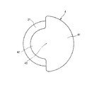
図4に示すように、この分銅4は、回転中心線43からの半径が比較的大きい大径部41と、回転中心線43からの半径が比較的小さい小径部42とで構成されており、この大径部41と小径部42とは、それぞれほぼ半周ずつ形成されている。これにより、分銅4は、大径部41側の重さが、小径部42側の重さよりも重くなっている。よって、分銅4の重心は、回転中心線43から大径部41側(図4中の右側)に所定距離偏心した位置にある。
【0059】
このように、分銅4は、その重心が回転中心線43から偏心した箇所に位置するようにされている。
【0060】
これにより、分銅4が回転中心線43を中心として回転すると、分銅4に作用する遠心力の不釣り合いにより、分銅4は、回転中心線43(差し込み部2の長手方向)に略垂直な方向の振動を発生する。
【0061】
このような分銅4の構成材料としては、特に限定されず、金属材料、非金属材料ともに使用することができるが、例えば、鉄、ステンレス鋼、チタン、タングステン、真鍮、または銅等の比較的比重が大きい金属材料が好ましく用いられる。これにより、分銅4の外形を小さくした場合でも、十分な振動が得られる。
【0062】
また、分銅4は、図示のような構成のものに限定されず、その重心が回転中心線43から偏心した位置にある(回転バランスが取れていない)ようなものであれば、いかなる形状、構造のものであってもよい。
【0063】
分銅4や差し込み部2の外表面の少なくとも一部には、処置具挿通チャンネル60の内面との摩擦抵抗を低減させる低摩擦抵抗材料が被覆されていてもよい。
この低摩擦抵抗材料としては、例えば、ポリテトラフルオロエチレン(PTFE)、テトラフルオロエチレン−ヘキサフルオロプロピレン共重合体(FEP)、パーフルオロアルコキシアルカン(PFA)、テトラフルオロエチレン−エチレン共重合体(ETFE)、ポリフッ化ビニリデン(PVDF)、ポリフッ化ビニル(PVF)、ポリクロロトリフルオロエチレン(PCTFE)、クロロトリフルオロエチレン−エチレン共重合体(ECTFE)、エチレン−テトラフルオロエチレン共重合体等、またはこれらから選択される少なくとも1種を含むポリマーアロイ(例えば、ポリマーブレンド、共重合体)等のフッ素系樹脂等が挙げられる。
【0064】
これにより、モータ5の回転力を高い効率で分銅4に伝達することができるとともに、処置具挿通チャンネル60の内壁を保護することもできる。
【0065】
また、処置具挿通チャンネル60の内面にも前述したような低摩擦抵抗材料が被覆されていてもよい。
【0066】
分銅4の回転により発生した振動は、内視鏡10の挿入部30に伝達され、挿入部30が振動する。
【0067】
このように挿入部30(の少なくとも一部)が振動することにより、管腔の内壁に対する挿入部30の密着(貼り付き)を防止(軽減)することができる。これにより、挿入部30が管腔の内壁から受ける摩擦抵抗(挿入抵抗)が低減され、よって、挿入部30を管腔の内部に挿入する操作の容易化を図ることができる。
【0068】
また、前述したように、分銅4は、挿入部30の長手方向に略垂直な方向の振動を発生するため、挿入部30の振動方向は、その長手方向に略垂直な方向になる。これにより、管腔の内壁に対する挿入部30の密着(貼り付き)を確実に防止(軽減)することができ、よって、挿入部30が管腔の内壁から受ける摩擦抵抗(挿入抵抗)を効果的に低減することができる。
【0069】
差し込み部2の長さは、使用対象とする内視鏡の種類、用途によってもその好ましい長さは異なるが、図2に示すように、差し込み部2の先端部が内視鏡10の挿入部30の先端部に位置し得るように設定されているのが好ましい。これにより、分銅4が挿入部30の先端部に位置し、挿入部30の先端側を重点的に振動させることができるため、特に挿入部30の先端側において、管腔の内壁に対する密着(貼り付き)がより効果的に防止(軽減)され、挿入部30の管腔に対する追従性が高い。
【0070】
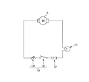
本実施形態の内視鏡用振動装置1には、分銅4が発生する振動の強弱を調整する振動調整手段として、モータ5の作動を制御するスイッチ付き可変抵抗器13が設けられている。このスイッチ付き可変抵抗器13は、図3に示すように、基部3の内部に設置されており、図5に示すように、スイッチ131としての機能と可変抵抗132としての機能とを併せ持っている。
【0071】
図5に示すように、モータ5およびスイッチ付き可変抵抗器13は、電池12に対し直列に電気的に接続されている。
【0072】
スイッチ付き可変抵抗器13の回転軸133は、基部3の蓋体32に形成された孔から外側に突出しており、該回転軸133にツマミ14が例えばネジ142により固定(固着)されている。スイッチ131の入/切(開閉)および可変抵抗132の抵抗値の調整は、このツマミ14を回すことにより操作することができるようになっている。
【0073】
図1に示すように、ツマミ14には、指標141が付されている。一方、ツマミ14の付近における蓋体32の外側には、「OFF」、「MIN」および「MAX」のマークがツマミ14の周方向に沿って所定の位置にそれぞれ付されている。そして、ツマミ14は、指標141が前記「OFF」マークの位置にある状態から前記「MIN」マークの位置を通過して前記「MAX」マークの位置にある状態までの範囲で、回動可能になっている。
【0074】
ツマミ14の指標141が前記「OFF」マークの位置にあるときは、スイッチ131が開状態となってモータ5に通電がなされず、モータ5は、停止する。
【0075】
この状態から指標141が前記「MIN」マークの位置に一致するまでツマミ14を回すと、スイッチ131が閉(入)状態となってモータ5に通電され、モータ5の回転軸51が所定の方向に回転する。このとき、回転軸51の回転の方向は、いずれの方向でもよい。
【0076】
このようにモータ5が駆動されると、差し込み部2とともに分銅4が回転し、これにより、分銅4は、振動を発生する。そして、これにともなって、挿入部30も振動する。
【0077】
ツマミ14の指標141が前記「MIN」マークの位置にある状態では、可変抵抗132の抵抗値が最大になり、これにより、モータ5の回転軸51および分銅4は、比較的遅い速度で回転する。このとき、分銅4が発生する振動は、比較的小さく、よって、挿入部30は、比較的弱く振動する。
【0078】
この状態からツマミ14をさらに図1中の時計方向に回すと、可変抵抗132の抵抗値が徐々に小さくなっていき、これにより、モータ5の回転軸51および分銅4の回転速度が徐々に速くなる。これにともなって、挿入部30の振動は、徐々に強くなる。
【0079】
そして、ツマミ14を図1中の時計方向に最大限に回した状態、すなわち、指標141が前記「MAX」マークの位置に一致した状態で、可変抵抗132の抵抗値が最小となり、このとき、モータ5の回転軸51および分銅4の回転速度は、最速となる。よって、この状態で、挿入部30は、最も強く振動する。
【0080】
このように、本実施形態においては、分銅4の発生する振動の強弱を自由に調整することができる。よって、状況に応じた最適な強さで、挿入部30の振動が得られる。
【0081】
これにより、例えば、体内における挿入目的部位が比較的浅い場合には、振動を弱くし、挿入目的部位が比較的深い場合には、振動を強くして使用することとしたり、挿入操作を行っている途中でそれ以上の挿入が困難になった場合に、挿入部30の振動の強さを増大させて挿入し易くしたりするようなことができる。
【0082】
<第2実施形態>
図6は、本発明の内視鏡用振動装置の第2実施形態を示す平面図、図7は、図6に示す内視鏡用振動装置におけるモータへの通電回路を示す回路図である。なお、以下の説明では、図6中の左側を「基端」、右側を「先端」と言う。
【0083】
以下、これらの図を参照して本発明の内視鏡用振動装置の第2実施形態について説明するが、前述した実施形態との相違点を中心に説明し、同様の事項はその説明を省略する。
【0084】
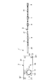
図6に示すように、本実施形態の内視鏡用振動装置1’では、差し込み部2に複数の分銅4が設置されている。これらの分銅4は、差し込み部2の長手方向に沿って設置されており、図示の構成では、差し込み部2のほぼ全長に渡って分銅4が配置されている。
【0085】
これらの分銅4のうちの少なくとも1つは、差し込み部2の先端部に設置されていることが好ましい。これにより、内視鏡10の挿入部30の先端部において、管腔の内壁に対する密着(貼り付き)がより効果的に防止(軽減)され、管腔に対する挿入部30の高い追従性が得られる。
【0086】
各分銅4同士は、それぞれ、コイル部21で接続されている。これにより、差し込み部2は、全体として可撓性を有しているとともに、湾曲した状態でもモータ5の回転力を各分銅4に高い効率で伝達することができる。
【0087】
分銅4の設置個数、設置間隔は、使用対象とする内視鏡の種類、用途等によってもその好ましい値は異なるが、通常、次のとおりである。
【0088】
すなわち、差し込み部2の全長が比較的短い場合には、先端側に2〜5個の分銅4を設置するのが好ましい。
【0089】
また、差し込み部2の全長が比較的長い場合には、好ましくは5〜40cm、より好ましくは10〜20cmの間隔で分銅4を挿入部30のほぼ全長に渡って設置することが好ましい。
【0090】
なお、3個以上の分銅4が設置されている場合、隣り合う分銅4同士の間隔は、一定でも、異なっていてもよい。
【0091】
本実施形態では、このように、複数設置された分銅4がそれぞれ振動を発生することにより、挿入部30を多箇所で、特にほぼ全体的に振動させることができる。これにより、管腔の内壁に対する挿入部30の密着(貼り付き)を挿入部30の全長に渡ってより確実に防止(軽減)することができる。よって、挿入部30が管腔の内壁から受ける摩擦抵抗(挿入抵抗)をより低減することができ、これにより、例えば挿入部30の全長が比較的長い内視鏡10に対して使用したような場合であっても、挿入の操作を容易に行うことができる。
【0092】
本実施形態の内視鏡用振動装置1’には、さらに、モータ5の作動状態を示す表示手段として、パイロットランプ15が設置されている。
【0093】
図6に示すように、このパイロットランプ15は、基部3(蓋体32)に設置されている。
【0094】
また、図7に示すように、モータ5への通電回路においては、パイロットランプ15は、モータ5と、電池12との間に接続されている。
【0095】
このような構成により、ツマミ14を操作してスイッチ131を閉(入)状態とすると、パイロットランプ15が点灯し、モータ5が作動していることを表示する。
【0096】
また、ツマミ14を回して、分銅4が発生する振動の強弱を調節すると、これにともなってパイロットランプ15に流れる電流が変化して、その明るさ(発光光量)が変化する。これにより、操作者は、パイロットランプ15の明るさ(発光光量)により、分銅4が発生する振動の強弱を把握することができる。
【0097】
本実施形態では、パイロットランプ15によって、操作者がモータ5の作動の有無や分銅4が発生する振動の強弱を容易に把握することができる。よって、より高い操作性および安全性が得られる。
【0098】
なお、パイロットランプ15のような表示手段の設置箇所は、図示の構成に限らず、差し込み部2以外の箇所であればいかなる箇所に設置されていてもよい。
【0099】
また、この表示手段としては、パイロットランプ15に限らず、例えば、発光素子の点灯数によって振動の強弱を示すピークインジケーターなどであってもよい。
【0100】
また、前記第1実施形態や後述する第3実施形態の内視鏡用振動装置1にもパイロットランプ15のような表示手段を設けてもよい。
【0101】
<第3実施形態>
図8は、本発明の内視鏡用振動装置の第3実施形態における基部と差し込み部との接続部付近を示す断面側面図、図9は、本発明の内視鏡用振動装置の第3実施形態における差し込み部を示す縦断面図である。なお、以下の説明では、図8および図9中の左側を「基端」、右側を「先端」と言う。
【0102】
以下、これらの図を参照して本発明の内視鏡用振動装置の第3実施形態について説明するが、前述した実施形態との相違点を中心に説明し、同様の事項はその説明を省略する。
【0103】
本実施形態の内視鏡用振動装置は、差し込み部の構成が異なること以外は、前記第1実施形態と同様である。
【0104】
本実施形態の内視鏡用振動装置における差し込み部6は、管体7と、該管体内に挿入された軸部材8とを有している。
【0105】
図8に示すように、管体7は、ケーシング31の先端部に固定(固着)された管状のパイプ部71と、該パイプ部71の先端側に固定(固着)され、帯状材を螺旋状に巻回して形成されたコイル部72とで構成されている。
このように、管体7は、基部3に対し固定されており、回転しない。
【0106】
軸部材8は、モータ5の回転軸51に固定(固着)された棒状のロッド部81と、該ロッド部81の先端側に固定(固着)され、可撓性を有するワイヤー部82とで構成されている。
【0107】
このように、軸部材8は、モータ5の回転軸51に固定されており、モータ5の駆動により、基部3(管体7)に対し回転する。
【0108】
パイプ部71およびロッド部81は、それぞれ、図2に示すのと同様の状態(内視鏡10に装着した状態)で、ほぼ操作部40の突出部420内に位置する部分に形成されている。
【0109】
一方、コイル部72およびワイヤー部82は、それぞれ、差し込み部6の全長の大半を構成している。
【0110】
なお、ワイヤー部82は、これに代えて、例えばコイル状に形成されたコイル部等で構成されていてもよい。
【0111】
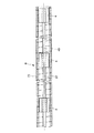
図9に示すように、ワイヤー部82には、その長手方向に沿って複数の分銅4が設置されている。
【0112】
このような構成により、モータ5が駆動されると、その回転が軸部材8によって各分銅4に伝達され、各分銅4がそれぞれ回転して振動を発生する。
これにより、本実施形態では、前記第2実施形態と同様の効果が得られる。
【0113】
さらに、本実施形態では、回転する分銅4および軸部材8が管体7の内部に収納されていることから、処置具挿通チャンネル60の内壁の磨耗等を防止することができ、処置具挿通チャンネル60の長寿命化が図れる。また、挿入部30が湾曲した状態でも、モータ5の回転力をより高い効率で分銅に伝達することができる。
【0114】
分銅4および軸部材8の外面や管体7の内面の少なくとも一部には、前記フッ素系材料等の低摩擦抵抗材料の被覆が施されていてもよい。これにより、モータ5の回転力をより高い効率で分銅4に伝達することができる。
【0115】
なお、本実施形態では、分銅4が管体7から露出していてもよい。また、管体7は、基部3に対し固定されていなくてもよい。また、軸部材8に設置された分銅4は、1個であってもよい。
【0116】
以上、本発明の内視鏡用振動装置を図示の実施形態について説明したが、本発明は、これに限定されるものではなく、内視鏡用振動装置を構成する各部は、同様の機能を発揮し得る任意の構成のものと置換することができる。
【0117】
【発明の効果】
以上述べたように、本発明によれば、内視鏡の挿入部を管腔内へ挿入する際に内視鏡の挿入部に作用する摩擦抵抗(挿入抵抗)を低減することができる。これにより、内視鏡における挿入操作の容易化を図ることができる。
【0118】
特に、使用対象とする内視鏡に特別の装備が不要であり、既存の内視鏡において上記効果を達成することができる。
【0119】
また、本発明の内視鏡用振動装置を使用して挿入操作を終えた後は、これを内視鏡から取り外すことにより、内視鏡の挿入部内に形成された通路を処置具挿通等の本来の用途に使用することができ、内視鏡の多機能性を損なうこともない。
【0120】
また、小型かつ極めて簡単な構造で上記効果を達成することができる。
また、管体および該管体内に挿入された軸部材を有する差し込み部を設け、該軸部材に分銅を設置した場合には、内視鏡の挿入部の内部に形成された通路の長寿命化を図ることができるとともに、駆動源の回転力をより高い効率で分銅に伝達することができる。
【図面の簡単な説明】
【図1】 内視鏡用振動装置の第1実施形態(参考例)を示す平面図である。
【図2】 図1に示す内視鏡用振動装置を内視鏡に装着した状態を示す図である。
【図3】 図1に示す内視鏡用振動装置における基部の断面側面図である。
【図4】 図1中のX−X線視図である。
【図5】 図1に示す内視鏡用振動装置におけるモータへの通電回路を示す回路図である。
【図6】 本発明の内視鏡用振動装置の第2実施形態を示す平面図である。
【図7】 図6に示す内視鏡用振動装置におけるモータへの通電回路を示す回路図である。
【図8】 本発明の内視鏡用振動装置の第3実施形態における基部と差し込み部との接続部付近を示す断面側面図である。
【図9】 本発明の内視鏡用振動装置の第3実施形態における差し込み部を示す縦断面図である。
【符号の説明】
1、1’ 内視鏡用振動装置
12 電池
13 スイッチ付き可変抵抗器
131 スイッチ
132 可変抵抗
133 回転軸
14 ツマミ
141 指標
142 ネジ
15 パイロットランプ
2 差し込み部
21 コイル部
22 ロッド部
3 基部
31 ケーシング
311 孔
32 蓋体
321 ネジ
33 ルアーロックナット
4 分銅
41 大径部
42 小径部
43 回転中心線
5 モータ
51 回転軸
6 差し込み部
7 管体
71 パイプ部
72 コイル部
8 軸部材
81 ロッド部
82 ワイヤー部
10 内視鏡
30 挿入部
310 挿入部可撓管
320 湾曲部
40 操作部
410 操作ノブ
420 突出部
50 接続部
60 処置具挿通チャンネル
610 先端開口部
620 基端開口部[0001]
BACKGROUND OF THE INVENTION
The present invention relates to an endoscope vibration device capable of facilitating an insertion operation by vibrating at least a part of an insertion portion of an endoscope.
[0002]
[Prior art]
In the medical field, endoscopes are used, for example, for examinations and treatments of the digestive tract and the like. Such an endoscope has a long insertion part having flexibility and an operation part provided on the proximal end side of the insertion part, and the insertion part is used as a lumen in a body (a tubular organ). Insert into the lumen).
[0003]
When inserting the insertion portion of the endoscope into the lumen, the insertion portion of the endoscope is moved by applying pushing force or twisting to the proximal end side (hand side) of the insertion portion of the endoscope. Advance in the lumen.
[0004]
However, since the insertion portion of the endoscope receives resistance due to friction with the inner wall of the lumen, it does not advance smoothly in the lumen, and the insertion operation is never easy. In particular, the operation of inserting deep into the body, such as the small intestine and large intestine, is difficult and requires a high degree of skill.
[0005]
[Problems to be solved by the invention]
An object of the present invention is to provide vibration to the insertion portion of the endoscope with a small and simple structure, thereby facilitating the operation of inserting the insertion portion of the endoscope into the lumen. Another object of the present invention is to provide an endoscope vibration device that can be used.
[0006]
[Means for Solving the Problems]
The purpose of this is as follows (1) to (8) This is achieved by the present invention.
[0007]
(1) the base,
A long insertion part that is rotatably provided with respect to the base part and can be inserted into a passage formed inside the insertion part of the endoscope;
A drive source installed on the base and for rotationally driving the insertion portion;
In the insertion part Multiple along its longitudinal direction Installed, and having a weight whose center of gravity is eccentric from the rotation center line,
An endoscope vibration device characterized in that at least a part of the insertion portion of the endoscope is vibrated by vibration generated by rotation of the weight.
[0008]
Accordingly, it is possible to provide an endoscope vibration device that can facilitate the operation of inserting the insertion portion of the endoscope into the lumen with a small and simple structure.
[0009]
(2) the base,
A long insertion portion that includes a tubular body and a shaft member inserted into the tubular body and can be inserted into a passage formed inside the insertion portion of the endoscope;
A drive source installed at the base and for rotationally driving the shaft member;
On the shaft member Multiple along its longitudinal direction Installed, and having a weight whose center of gravity is eccentric from the rotation center line,
An endoscope vibration device characterized in that at least a part of the insertion portion of the endoscope is vibrated by vibration generated by rotation of the weight.
[0010]
Accordingly, it is possible to provide an endoscope vibration device that can facilitate the operation of inserting the insertion portion of the endoscope into the lumen with a small and simple structure.
[0013]
(3) The weight is provided at least at the tip of the insertion part. (1) or (2) above The endoscope vibration device according to 1.
[0014]
As a result, since the distal end portion of the insertion portion of the endoscope is vibrated predominantly, the followability of the insertion portion of the endoscope with respect to the lumen can be enhanced, and the insertion operation can be further facilitated.
[0015]
(4) The insertion portion has flexibility. (1) to (3) above The endoscope vibration device according to any one of the above.
[0016]
Thereby, the insertion operation can be performed more easily without impairing the flexibility of the insertion portion of the endoscope.
[0017]
(5) The insertion portion has a portion formed in a coil shape. (1) to (4) above The endoscope vibration device according to any one of the above.
Thereby, the rotational force of a drive source can be transmitted to a weight with high efficiency.
[0018]
(6) The base can be fixed to the endoscope. (1) to (5) above The endoscope vibration device according to any one of the above.
Thereby, high operability is obtained.
[0019]
(7) It has a vibration adjusting means for adjusting the strength of vibration generated by the weight. (1) to (6) above The endoscope vibration device according to any one of the above.
Thereby, the vibration of the insertion portion can be obtained with an optimum strength according to the situation.
[0020]
(8) It has a display means which shows the operating state of the drive source at a place other than the insertion part. (1) to (7) above The endoscope vibration device according to any one of the above.
[0021]
Thereby, the operator can easily grasp the operating state of the drive source, and higher operability and safety can be obtained.
[0022]
DETAILED DESCRIPTION OF THE INVENTION
Hereinafter, an endoscope vibration device of the present invention will be described in detail based on preferred embodiments shown in the accompanying drawings.
[0023]
<First Embodiment>
FIG. Endoscopy vibrator First Embodiment (Reference example) FIG. 2 is a diagram showing a state in which the endoscope vibration device shown in FIG. 1 is attached to the endoscope, and FIG. 3 is a cross-sectional side view of the base in the endoscope vibration device shown in FIG. 4 is a view taken along line XX in FIG. 1, and FIG. 5 is a circuit diagram showing an energization circuit to a motor in the endoscope vibration device shown in FIG. In the following description, the left side in FIGS. 1 to 3 is referred to as a “base end”, and the right side is referred to as a “tip”.
[0024]
First, an example of an endoscope to be used for the endoscope vibration device of the present invention will be described.
[0025]
An endoscope (electronic scope) 10 shown in FIG. 2 is connected to a
[0026]
The
[0027]
The insertion portion
[0028]
A bending
[0029]
Although not shown in the figure, the
[0030]
A treatment instrument insertion channel (passage) 60 is formed in the
[0031]
An imaging element (CCD) (not shown) that captures a subject image at the observation site is provided at the distal end of the insertion unit 30 (curving unit 320).
[0032]
A proximal end portion of the
[0033]
In the vicinity of the distal end of the operation unit 40, a
The
[0034]
After inserting the
[0035]
One end of the
[0036]
An image signal connector and a light source connector (not shown) are provided on the other end side of the connecting
[0037]
The light source processor device is connected to a monitor device (not shown) via a cable (not shown).
[0038]
A light source is installed inside the light source processor device, and the light emitted from the light source passes through the light guide continuously disposed in the
[0039]
The reflected light (subject image) from the observation site illuminated by the illumination light is imaged by the imaging element. An image signal corresponding to the subject image captured by the image sensor is output via a buffer (not shown).
[0040]
The image signal is continuously disposed in the
[0041]
Then, predetermined processing (for example, signal processing, image processing, etc.) is performed in the light source processor device, and then input to the monitor device. In the monitor device, an image (electronic image) captured by the image sensor, that is, a video endoscope monitor image is displayed.
[0042]
Needless to say, the endoscope vibration device of the present invention can be used not only for an electronic endoscope such as the
[0043]
Next, the endoscope vibration device of the present invention will be described.
As shown in FIG. 1, the endoscope vibration device 1 is provided with a
[0044]
As shown in FIG. 2, the endoscope vibration device 1 is used by inserting the insertion portion 2 into a treatment
[0045]
As shown in FIGS. 1 and 3, the
[0046]
As shown in FIG. 3, a
[0047]
A
[0048]
A
[0049]
With such a configuration, as shown in FIG. 2, the endoscope vibration device 1 has the
[0050]
When the
[0051]
After the
[0052]
As shown in FIGS. 1 and 3, the insertion portion 2 is fixed (fixed) to a rod-shaped
[0053]
In the state shown in FIG. 2, the
[0054]
The
[0055]
Thereby, the insertion part 2 has flexibility, and can be freely curved according to the curve of the
[0056]
A weight 4 that generates vibration by rotating is fixed (fixed) to the tip of the
[0057]
Thereby, when the
[0058]
As shown in FIG. 4, the weight 4 includes a large-
[0059]
In this manner, the weight 4 is positioned at a location where the center of gravity is eccentric from the
[0060]
As a result, when the weight 4 rotates about the
[0061]
The constituent material of the weight 4 is not particularly limited and can be used for both metal materials and non-metal materials. For example, iron, stainless steel, titanium, tungsten, brass, or copper has a relatively specific gravity. Is preferably used. Thereby, even when the external shape of the weight 4 is reduced, sufficient vibration can be obtained.
[0062]
Further, the weight 4 is not limited to the one having the configuration shown in the figure, and any shape and structure may be used as long as the center of gravity is in an eccentric position from the rotation center line 43 (the rotation is not balanced). It may be.
[0063]
At least a part of the outer surface of the weight 4 or the insertion portion 2 may be coated with a low friction resistance material that reduces the friction resistance with the inner surface of the treatment
Examples of the low friction resistance material include polytetrafluoroethylene (PTFE), tetrafluoroethylene-hexafluoropropylene copolymer (FEP), perfluoroalkoxyalkane (PFA), and tetrafluoroethylene-ethylene copolymer (ETFE). ), Polyvinylidene fluoride (PVDF), polyvinyl fluoride (PVF), polychlorotrifluoroethylene (PCTFE), chlorotrifluoroethylene-ethylene copolymer (ECTFE), ethylene-tetrafluoroethylene copolymer, or the like Fluorine resins such as polymer alloys (for example, polymer blends, copolymers) containing at least one selected from
[0064]
Accordingly, the rotational force of the
[0065]
Further, the inner surface of the treatment
[0066]
The vibration generated by the rotation of the weight 4 is transmitted to the
[0067]
As described above, at least a part of the
[0068]
Further, as described above, the weight 4 generates vibration in a direction substantially perpendicular to the longitudinal direction of the
[0069]
Although the preferable length of the insertion portion 2 varies depending on the type and application of the endoscope to be used, as shown in FIG. 2, the distal end portion of the insertion portion 2 is the insertion portion of the
[0070]
The endoscope vibration device 1 according to the present embodiment is provided with a
[0071]
As shown in FIG. 5, the
[0072]
The
[0073]
As shown in FIG. 1, an
[0074]
When the
[0075]
From this state, when the
[0076]
When the
[0077]
In a state where the
[0078]
When the
[0079]
Then, in the state where the
[0080]
Thus, in this embodiment, the strength of vibration generated by the weight 4 can be freely adjusted. Therefore, the vibration of the
[0081]
As a result, for example, when the insertion target site in the body is relatively shallow, the vibration is weakened. When the insertion target site is relatively deep, the vibration is increased or the insertion operation is performed. When further insertion becomes difficult in the middle of being, the strength of vibration of the
[0082]
<Second Embodiment>
FIG. 6 is a plan view showing a second embodiment of the endoscope vibration device of the present invention, and FIG. 7 is a circuit diagram showing an energization circuit to a motor in the endoscope vibration device shown in FIG. In the following description, the left side in FIG. 6 is referred to as “base end”, and the right side is referred to as “tip”.
[0083]
Hereinafter, the second embodiment of the endoscope vibration device of the present invention will be described with reference to these drawings. However, the description will focus on the differences from the above-described embodiment, and the description of the same matters will be omitted. To do.
[0084]
As shown in FIG. 6, in the endoscope vibration device 1 ′ of this embodiment, a plurality of weights 4 are installed in the insertion portion 2. These weights 4 are installed along the longitudinal direction of the insertion portion 2, and in the illustrated configuration, the weights 4 are arranged over almost the entire length of the insertion portion 2.
[0085]
At least one of these weights 4 is preferably installed at the tip of the insertion portion 2. Thereby, in the front-end | tip part of the
[0086]
The weights 4 are connected to each other by a
[0087]
The preferred values of the number of weights 4 and the interval between them vary depending on the type of endoscope to be used, the purpose of use, etc., but are generally as follows.
[0088]
That is, when the total length of the insertion part 2 is relatively short, it is preferable to install 2 to 5 weights 4 on the tip side.
[0089]
When the entire length of the insertion portion 2 is relatively long, it is preferable that the weight 4 is installed over the substantially entire length of the
[0090]
When three or more weights 4 are installed, the distance between adjacent weights 4 may be constant or different.
[0091]
In the present embodiment, the plurality of weights 4 installed in this manner generate vibrations, respectively, so that the
[0092]
In the endoscope vibration device 1 ′ of the present embodiment, a
[0093]
As shown in FIG. 6, the
[0094]
As shown in FIG. 7, in the energization circuit for the
[0095]
With such a configuration, when the
[0096]
Further, when the
[0097]
In the present embodiment, the
[0098]
The installation location of the display means such as the
[0099]
Further, the display means is not limited to the
[0100]
Further, display means such as the
[0101]
<Third Embodiment>
FIG. 8 is a cross-sectional side view showing the vicinity of the connecting portion between the base portion and the insertion portion in the third embodiment of the endoscope vibration device of the present invention, and FIG. 9 is a third view of the endoscope vibration device of the present invention. It is a longitudinal cross-sectional view which shows the insertion part in embodiment. In the following description, the left side in FIGS. 8 and 9 is referred to as a “base end”, and the right side is referred to as a “tip”.
[0102]
Hereinafter, the third embodiment of the endoscope vibration device of the present invention will be described with reference to these drawings. However, the description will focus on differences from the above-described embodiment, and the description of the same matters will be omitted. To do.
[0103]
The endoscope vibration device of this embodiment is the same as that of the first embodiment except that the configuration of the insertion portion is different.
[0104]
The insertion portion 6 in the endoscope vibration device according to the present embodiment includes a tube body 7 and a shaft member 8 inserted into the tube body.
[0105]
As shown in FIG. 8, the tubular body 7 has a
Thus, the tubular body 7 is fixed with respect to the
[0106]
The shaft member 8 includes a rod-shaped
[0107]
As described above, the shaft member 8 is fixed to the
[0108]
Each of the
[0109]
On the other hand, the
[0110]
Instead of this, the
[0111]
As shown in FIG. 9, a plurality of weights 4 are installed in the
[0112]
With this configuration, when the
Thereby, in this embodiment, the effect similar to the said 2nd Embodiment is acquired.
[0113]
Furthermore, in the present embodiment, since the rotating weight 4 and the shaft member 8 are housed inside the tube body 7, the inner wall of the treatment
[0114]
At least a part of the outer surface of the weight 4 and the shaft member 8 and the inner surface of the tube body 7 may be coated with a low friction resistance material such as the fluorine-based material. Thereby, the rotational force of the
[0115]
In the present embodiment, the weight 4 may be exposed from the tube body 7. Further, the tube body 7 may not be fixed to the
[0116]
As described above, the endoscope vibration device according to the present invention has been described with respect to the illustrated embodiment. However, the present invention is not limited to this, and each part constituting the endoscope vibration device has the same function. It can be replaced with any configuration that can be exhibited.
[0117]
【The invention's effect】
As described above, according to the present invention, it is possible to reduce the frictional resistance (insertion resistance) acting on the insertion portion of the endoscope when the insertion portion of the endoscope is inserted into the lumen. Thereby, the insertion operation in the endoscope can be facilitated.
[0118]
In particular, no special equipment is required for an endoscope to be used, and the above-described effects can be achieved in an existing endoscope.
[0119]
In addition, after finishing the insertion operation using the endoscope vibration device of the present invention, by removing the endoscope from the endoscope, the passage formed in the insertion portion of the endoscope can be inserted into the treatment instrument. It can be used for original purposes and does not impair the multi-functionality of the endoscope.
[0120]
In addition, the above-described effects can be achieved with a small and extremely simple structure.
Further, when a tube body and an insertion portion having a shaft member inserted into the tube body are provided and a weight is installed on the shaft member, the life of the passage formed inside the insertion portion of the endoscope is extended. In addition, the rotational force of the drive source can be transmitted to the weight with higher efficiency.
[Brief description of the drawings]
[Figure 1] Endoscopy vibrator First Embodiment (Reference example) FIG.
FIG. 2 is a diagram showing a state where the endoscope vibration device shown in FIG. 1 is attached to the endoscope.
3 is a cross-sectional side view of a base portion in the endoscope vibration device shown in FIG. 1; FIG.
4 is a XX line view in FIG. 1. FIG.
5 is a circuit diagram showing an energization circuit to a motor in the endoscope vibration device shown in FIG. 1; FIG.
FIG. 6 is a plan view showing a second embodiment of the vibration device for an endoscope of the present invention.
7 is a circuit diagram showing an energization circuit for a motor in the endoscope vibration device shown in FIG. 6; FIG.
FIG. 8 is a cross-sectional side view showing the vicinity of a connection portion between a base portion and an insertion portion in a third embodiment of the vibration device for an endoscope of the present invention.
FIG. 9 is a longitudinal sectional view showing an insertion portion in a third embodiment of an endoscope vibration apparatus of the present invention.
[Explanation of symbols]
1, 1 'Endoscope vibration device
12 batteries
13 Variable resistor with switch
131 switch
132 Variable resistance
133 Rotating shaft
14 Knob
141 indicators
142 screws
15 Pilot lamp
2 Insertion section
21 Coil part
22 Rod part
3 base
31 Casing
311 hole
32 Lid
321 screws
33 Luer lock nut
4 Weight
41 Large diameter part
42 Small diameter part
43 Center of rotation
5 Motor
51 Rotating shaft
6 Insertion part
7 Tube
71 Pipe section
72 Coil part
8 shaft member
81 Rod part
82 Wire part
10 Endoscope
30 Insertion part
310 Insertion section flexible tube
320 Curved part
40 Operation unit
410 Operation knob
420 Protrusion
50 connections
60 treatment instrument insertion channel
610 Tip opening
620 Base end opening
Claims (8)
前記基部に対し回転可能に設けられ、内視鏡の挿入部の内部に形成された通路内に挿入可能な長尺の差し込み部と、
前記基部に設置され、前記差し込み部を回転駆動する駆動源と、
前記差し込み部にその長手方向に沿って複数設置され、その重心が回転中心線から偏心した位置にある分銅とを有し、
前記分銅が回転して発生する振動により、前記内視鏡の挿入部の少なくとも一部を振動させることを特徴とする内視鏡用振動装置。The base,
A long insertion part that is rotatably provided with respect to the base part and can be inserted into a passage formed inside the insertion part of the endoscope;
A drive source installed on the base and for rotationally driving the insertion portion;
A plurality of weights are installed along the longitudinal direction of the insertion portion, and the weight is located at a position eccentric from the rotation center line.
An endoscope vibration device characterized in that at least a part of the insertion portion of the endoscope is vibrated by vibration generated by rotation of the weight.
管体および該管体内に挿入された軸部材を備え、内視鏡の挿入部の内部に形成された通路内に挿入可能な長尺の差し込み部と、
前記基部に設置され、前記軸部材を回転駆動する駆動源と、
前記軸部材にその長手方向に沿って複数設置され、その重心が回転中心線から偏心した位置にある分銅とを有し、
前記分銅が回転して発生する振動により、前記内視鏡の挿入部の少なくとも一部を振動させることを特徴とする内視鏡用振動装置。The base,
A long insertion portion that includes a tubular body and a shaft member inserted into the tubular body and can be inserted into a passage formed inside the insertion portion of the endoscope;
A drive source installed at the base and for rotationally driving the shaft member;
A plurality of shaft members are installed along the longitudinal direction of the shaft member, and the center of gravity of the shaft member has a weight eccentric from the rotation center line.
An endoscope vibration device characterized in that at least a part of the insertion portion of the endoscope is vibrated by vibration generated by rotation of the weight.
Priority Applications (1)
| Application Number | Priority Date | Filing Date | Title |
|---|---|---|---|
| JP2001082206A JP4611552B2 (en) | 2001-03-22 | 2001-03-22 | Endoscopy vibrator |
Applications Claiming Priority (1)
| Application Number | Priority Date | Filing Date | Title |
|---|---|---|---|
| JP2001082206A JP4611552B2 (en) | 2001-03-22 | 2001-03-22 | Endoscopy vibrator |
Publications (2)
| Publication Number | Publication Date |
|---|---|
| JP2002282204A JP2002282204A (en) | 2002-10-02 |
| JP4611552B2 true JP4611552B2 (en) | 2011-01-12 |
Family
ID=18938179
Family Applications (1)
| Application Number | Title | Priority Date | Filing Date |
|---|---|---|---|
| JP2001082206A Expired - Fee Related JP4611552B2 (en) | 2001-03-22 | 2001-03-22 | Endoscopy vibrator |
Country Status (1)
| Country | Link |
|---|---|
| JP (1) | JP4611552B2 (en) |
Families Citing this family (3)
| Publication number | Priority date | Publication date | Assignee | Title |
|---|---|---|---|---|
| JP5204562B2 (en) * | 2008-06-20 | 2013-06-05 | オリンパス株式会社 | Endoscope overtube and endoscope overtube system |
| JP6398002B2 (en) | 2015-05-28 | 2018-09-26 | オリンパス株式会社 | Flexible tube insertion device |
| KR102143070B1 (en) | 2018-09-20 | 2020-08-10 | 연세대학교 산학협력단 | Endoscope surgery device |
Family Cites Families (8)
| Publication number | Priority date | Publication date | Assignee | Title |
|---|---|---|---|---|
| JPS5233440A (en) * | 1975-09-10 | 1977-03-14 | Oki Univac Kk | Automatic wiring test system |
| JPH03275027A (en) * | 1990-03-26 | 1991-12-05 | Olympus Optical Co Ltd | Endoscope apparatus |
| JP3279410B2 (en) * | 1993-10-22 | 2002-04-30 | オリンパス光学工業株式会社 | Endoscope |
| JPH07124173A (en) * | 1993-11-02 | 1995-05-16 | Olympus Optical Co Ltd | Control system for medical treatment |
| JPH09215660A (en) * | 1996-02-13 | 1997-08-19 | Fuji Photo Optical Co Ltd | Image generating device for endoscope |
| JP3798871B2 (en) * | 1997-03-12 | 2006-07-19 | オリンパス株式会社 | Endoscope system |
| JPH11114495A (en) * | 1997-10-13 | 1999-04-27 | Mitsumi Electric Co Ltd | Fixing method of weight in vibration motor |
| JPH11347734A (en) * | 1998-06-02 | 1999-12-21 | Akihiro Saito | Welding wire feeding tube |
-
2001
- 2001-03-22 JP JP2001082206A patent/JP4611552B2/en not_active Expired - Fee Related
Also Published As
| Publication number | Publication date |
|---|---|
| JP2002282204A (en) | 2002-10-02 |
Similar Documents
| Publication | Publication Date | Title |
|---|---|---|
| US9763561B2 (en) | Attachment unit and endoscope | |
| US8287446B2 (en) | Vibratory device, endoscope having such a device, method for configuring an endoscope, and method of reducing looping of an endoscope | |
| WO2006090599A1 (en) | Endoscope device | |
| JP2003230536A (en) | Electric curving endoscope | |
| US11986411B2 (en) | Devices and methods for treatment of body lumens | |
| JP4864003B2 (en) | Rotating self-propelled endoscope device | |
| US20250082348A1 (en) | Automated method of removing clog within lumen for debris removal | |
| EP2898816A1 (en) | Insertion aid, insertion body, and insertion device | |
| JP2006334246A (en) | Endoscope apparatus | |
| JP4611552B2 (en) | Endoscopy vibrator | |
| JP4520485B2 (en) | Electric bending endoscope | |
| JP2002263054A (en) | Vibration device for endoscope | |
| JP4583809B2 (en) | Endoscope and endoscope apparatus | |
| JP2002233497A (en) | Endoscope | |
| JP2007307241A (en) | Rotating self-propelled endoscope and rotating self-propelled endoscope apparatus | |
| JPH0624804Y2 (en) | Tip optical adapter | |
| JP4708579B2 (en) | Endoscope parts and endoscopes | |
| JP4745494B2 (en) | Endoscope | |
| WO2006123398A1 (en) | Insertion section for insertion device, and insertion device | |
| JP3898886B2 (en) | Endoscope | |
| JP2002291688A (en) | Endoscope | |
| WO2021176719A1 (en) | Insertion device | |
| WO2007057962A1 (en) | Rotary self-propelled endoscope device | |
| JP2008194080A (en) | Body cavity advance / retreat device |
Legal Events
| Date | Code | Title | Description |
|---|---|---|---|
| A621 | Written request for application examination |
Free format text: JAPANESE INTERMEDIATE CODE: A621 Effective date: 20080125 |
|
| A711 | Notification of change in applicant |
Free format text: JAPANESE INTERMEDIATE CODE: A712 Effective date: 20080430 |
|
| A977 | Report on retrieval |
Free format text: JAPANESE INTERMEDIATE CODE: A971007 Effective date: 20100709 |
|
| A131 | Notification of reasons for refusal |
Free format text: JAPANESE INTERMEDIATE CODE: A131 Effective date: 20100720 |
|
| A521 | Request for written amendment filed |
Free format text: JAPANESE INTERMEDIATE CODE: A523 Effective date: 20100901 |
|
| TRDD | Decision of grant or rejection written | ||
| A01 | Written decision to grant a patent or to grant a registration (utility model) |
Free format text: JAPANESE INTERMEDIATE CODE: A01 Effective date: 20100921 |
|
| A01 | Written decision to grant a patent or to grant a registration (utility model) |
Free format text: JAPANESE INTERMEDIATE CODE: A01 |
|
| A61 | First payment of annual fees (during grant procedure) |
Free format text: JAPANESE INTERMEDIATE CODE: A61 Effective date: 20101014 |
|
| FPAY | Renewal fee payment (event date is renewal date of database) |
Free format text: PAYMENT UNTIL: 20131022 Year of fee payment: 3 |
|
| R150 | Certificate of patent or registration of utility model |
Free format text: JAPANESE INTERMEDIATE CODE: R150 |
|
| LAPS | Cancellation because of no payment of annual fees |