JP4610304B2 - X-ray CT system - Google Patents
X-ray CT system Download PDFInfo
- Publication number
- JP4610304B2 JP4610304B2 JP2004322442A JP2004322442A JP4610304B2 JP 4610304 B2 JP4610304 B2 JP 4610304B2 JP 2004322442 A JP2004322442 A JP 2004322442A JP 2004322442 A JP2004322442 A JP 2004322442A JP 4610304 B2 JP4610304 B2 JP 4610304B2
- Authority
- JP
- Japan
- Prior art keywords
- ray
- image
- center axis
- rotation center
- phantom
- Prior art date
- Legal status (The legal status is an assumption and is not a legal conclusion. Google has not performed a legal analysis and makes no representation as to the accuracy of the status listed.)
- Expired - Fee Related
Links
- 238000012937 correction Methods 0.000 claims description 82
- 238000004364 calculation method Methods 0.000 claims description 78
- 238000012545 processing Methods 0.000 claims description 25
- 238000013461 design Methods 0.000 claims description 21
- 238000006073 displacement reaction Methods 0.000 claims description 9
- 230000001678 irradiating effect Effects 0.000 claims 2
- 238000000034 method Methods 0.000 description 49
- 238000003384 imaging method Methods 0.000 description 40
- 230000005540 biological transmission Effects 0.000 description 23
- 238000010586 diagram Methods 0.000 description 16
- 238000001914 filtration Methods 0.000 description 13
- 238000007781 pre-processing Methods 0.000 description 12
- 238000010521 absorption reaction Methods 0.000 description 8
- 239000002184 metal Substances 0.000 description 8
- 238000003860 storage Methods 0.000 description 5
- 238000009826 distribution Methods 0.000 description 4
- 238000004519 manufacturing process Methods 0.000 description 4
- 238000001514 detection method Methods 0.000 description 3
- 210000001015 abdomen Anatomy 0.000 description 2
- 238000004422 calculation algorithm Methods 0.000 description 2
- 238000006243 chemical reaction Methods 0.000 description 2
- 238000007796 conventional method Methods 0.000 description 2
- 238000011156 evaluation Methods 0.000 description 2
- 239000000463 material Substances 0.000 description 2
- 241001669679 Eleotris Species 0.000 description 1
- 230000001133 acceleration Effects 0.000 description 1
- 238000005553 drilling Methods 0.000 description 1
- 239000004973 liquid crystal related substance Substances 0.000 description 1
- 230000003287 optical effect Effects 0.000 description 1
- 238000007493 shaping process Methods 0.000 description 1
- 230000009466 transformation Effects 0.000 description 1
Images


Classifications
-
- A—HUMAN NECESSITIES
- A61—MEDICAL OR VETERINARY SCIENCE; HYGIENE
- A61B—DIAGNOSIS; SURGERY; IDENTIFICATION
- A61B6/00—Apparatus or devices for radiation diagnosis; Apparatus or devices for radiation diagnosis combined with radiation therapy equipment
- A61B6/58—Testing, adjusting or calibrating thereof
- A61B6/582—Calibration
- A61B6/583—Calibration using calibration phantoms
- A61B6/584—Calibration using calibration phantoms determining position of components of the apparatus or device using images of the phantom
Landscapes
- Health & Medical Sciences (AREA)
- Life Sciences & Earth Sciences (AREA)
- Medical Informatics (AREA)
- Engineering & Computer Science (AREA)
- Radiology & Medical Imaging (AREA)
- Biomedical Technology (AREA)
- Biophysics (AREA)
- Nuclear Medicine, Radiotherapy & Molecular Imaging (AREA)
- Optics & Photonics (AREA)
- Pathology (AREA)
- Physics & Mathematics (AREA)
- High Energy & Nuclear Physics (AREA)
- Heart & Thoracic Surgery (AREA)
- Molecular Biology (AREA)
- Surgery (AREA)
- Animal Behavior & Ethology (AREA)
- General Health & Medical Sciences (AREA)
- Public Health (AREA)
- Veterinary Medicine (AREA)
- Apparatus For Radiation Diagnosis (AREA)
Description
本発明は、X線CT装置に係り、特に、本発明は、2次元X線検出器による回転撮影データから、3次元的X線CT像を再構成するのに有効な技術に関する。 The present invention relates to an X-ray CT apparatus, and in particular, the present invention relates to a technique effective for reconstructing a three-dimensional X-ray CT image from rotational imaging data obtained by a two-dimensional X-ray detector.
従来のコーンビームX線CT装置は、X線源とこのX線源に対向して配置される2次元X線検出器(X線イメージインテンシファイアとテレビカメラとを組み合わせたものを含む。)とを同一回転中心の円軌道面上で回転移動させながら、回転中心軸上に位置する被検体のX線透視像を2次元X線検出器で撮影し、更に前記X線透視像を基に画像再構成演算を行うことによって、3次元的X線CT像を得るものである。 A conventional cone beam X-ray CT apparatus includes an X-ray source and a two-dimensional X-ray detector disposed opposite to the X-ray source (including a combination of an X-ray image intensifier and a television camera). Are rotated on a circular orbital plane having the same rotation center, and an X-ray fluoroscopic image of the subject located on the rotation central axis is taken with a two-dimensional X-ray detector, and further, based on the X-ray fluoroscopic image. A three-dimensional X-ray CT image is obtained by performing an image reconstruction operation.
このような2次元X線検出器を用いたコーンビームX線CT装置の画像再構成演算アルゴリズムとして、非特許文献1に記載のフェルドカンプの方法が代表的である。
As an image reconstruction calculation algorithm of a cone beam X-ray CT apparatus using such a two-dimensional X-ray detector, the Feldkamp method described in Non-Patent
また、コーンビームX線CT装置では機械的製作誤差に伴うアーチファクトのない3次元的X線CT像を得るために、回転中心軸の設計位置とのずれや、X線源の焦点の軌道を含む平面である回転軌道面等をパラメータ(以下、幾何学パラメータと称す)として求め、画像再構成演算において補正しながら演算することがある。幾何学パラメータを求める方法として特許文献1及び特許文献2、またガントリタイプのコーンビームX線CT装置の回転中心軸を精度良く求める方法として特許文献3に記載の従来技術がある。
In addition, in the cone beam X-ray CT apparatus, in order to obtain a three-dimensional X-ray CT image free from artifacts due to mechanical manufacturing errors, a shift from the design position of the rotation center axis and the trajectory of the focal point of the X-ray source are included. There are cases where a rotational orbital surface, which is a plane, is obtained as a parameter (hereinafter referred to as a geometric parameter) and is corrected while being corrected in an image reconstruction calculation. There are conventional techniques described in
特許文献1は、X線吸収係数の大きな小金属球を撮影し、その投影像のサイノグラムからのずれを用い、回転中心の幾何学補正を行う方法を開示する。
特許文献2は、棒状の支持体にX線吸収係数の大きい小金属球を複数個入れたファントムを回転中心軸に平行に配置して、360度回転撮影し、その金属球が2次元X線透過像上に描く楕円軌道を利用して、回転軌道面、回転中心軸、検出器取付け補正角などの幾何学パラメータを求める方法を開示する。 In Patent Document 2, a phantom in which a plurality of small metal spheres having a large X-ray absorption coefficient are placed on a rod-like support is arranged in parallel to the rotation center axis, and rotated 360 degrees, and the metal spheres are two-dimensional X-rays. Disclosed is a method for obtaining geometric parameters such as a rotation orbit plane, a rotation center axis, and a detector mounting correction angle using an elliptical orbit drawn on a transmission image.
特許文献3は、X線吸収係数の大きなワイヤー線を撮影し、評価関数によりその3次元的X線CT像の鮮明度を評価しながら再構成演算で使用する幾何学パラメータ、回転中心軸投影を精度良く求める方法を開示する。
本発明者は、前記従来技術による撮影系幾何学パラメータの決定方法を検討した結果、以下の問題点を見いだした。 As a result of studying the method for determining the imaging system geometric parameter according to the conventional technique, the present inventor has found the following problems.
特許文献1に記載の幾何学パラメータ補正方法は、投影像上での補間演算を用いた幾何学パラメータ調整方法である。そのためCT再構成に必要な精度が出ない場合があるという問題があった。
The geometric parameter correction method described in
特許文献2に記載の幾何学パラメータ補正方法も、投影像上での補間演算を用いた幾何学パラメータ調整方法であるため、CT再構成に必要な精度が出ないという問題がある。 The geometric parameter correction method described in Patent Document 2 is also a geometric parameter adjustment method using an interpolation operation on a projected image, and thus has a problem that the accuracy necessary for CT reconstruction cannot be obtained.
また特許文献3に記載の回転中心軸算出方法は、ワイヤー断面の再構成像をそのアーチファクトを含め、評価関数でその鮮明度を評価しながら幾何学パラメータを求めていく手法であるため、ガントリタイプのように回転軌道の真円性の高いコーンビームX線CT装置では精度良く回転中心軸を算出することができるが、C型アームのようにたわみやぶれがある回転軌道の場合には正しい幾何学パラメータが得られないという問題がある。 In addition, the rotation center axis calculation method described in Patent Document 3 is a method of obtaining geometric parameters while evaluating the sharpness with an evaluation function including the artifacts in the reconstructed image of the wire cross section. The cone beam X-ray CT apparatus having a high roundness of the rotation trajectory can calculate the rotation center axis with high accuracy. However, in the case of the rotation trajectory with deflection and shake like the C-type arm, the correct geometry There is a problem that parameters cannot be obtained.
本発明はこのような事情に鑑みてなされたもので、2次元X線検出器による回転撮影データ、特にC型アームによる180°+検出器開き角の回転撮影データから、鮮明な3次元的X線CT像を再構成するための、幾何学パラメータの決定方法を提供することを目的とする。 The present invention has been made in view of such circumstances. From the rotational imaging data by the two-dimensional X-ray detector, in particular, from the rotational imaging data of 180 ° + detector opening angle by the C-type arm, a clear three-dimensional X-ray is obtained. It is an object of the present invention to provide a geometric parameter determination method for reconstructing a line CT image.
前記目的を達成するために、本発明に係るX線CT装置は、被検体にX線を照射するX線源と、前記X線源に対向して配置され、前記被検体を透過した前記X線を検出して前記被検体のX線画像データを出力する2次元X線検出器と、前記X線源及び前記2次元X線検出器を回転移動させるための回転手段と、前記X線画像データに基づいて画像再構成演算を行なう逆投影手段を備えた画像処理装置と、を備えたX線CT装置において、前記画像処理装置は、前記回転手段による回転移動により示される設計上の回転中心軸の位置と、前記回転手段による実際の回転移動により示される回転中心軸の位置と、の相対変位量を、前記設計上の回転中心軸の近傍に位置したファントムの再構成像の半径の差に基づいて算出する回転中心軸投影位置計算手段を備え、前記逆投影手段は、前記相対変位量に基づいて前記X線画像データの修正を行い、画像を再構成する、ことを特徴とする。 In order to achieve the object, an X-ray CT apparatus according to the present invention includes an X-ray source that irradiates a subject with X-rays, and the X-ray that is disposed to face the X-ray source and transmits the subject. A two-dimensional X-ray detector for detecting a line and outputting X-ray image data of the subject, a rotating means for rotating the X-ray source and the two-dimensional X-ray detector, and the X-ray image An X-ray CT apparatus including a back projection unit that performs image reconstruction calculation based on data, wherein the image processing unit is a design rotation center indicated by a rotational movement by the rotation unit The relative displacement between the position of the shaft and the position of the rotation center axis indicated by the actual rotational movement by the rotation means is the difference in the radius of the reconstructed image of the phantom located in the vicinity of the designed rotation center axis. Rotation center axis projection position calculated based on Comprising a calculation unit, the inverse projection unit performs a correction of the X-ray image data based on the relative displacement amount, reconstructing an image, characterized in that.
また、本発明に係るX線CT装置は、被検体にX線を照射するX線源と、前記X線源に対向して配置され、前記被検体を透過した前記X線を検出して前記被検体のX線画像データを出力する2次元X線検出器と、前記X線源及び前記2次元X線検出器を回転移動させるための回転手段と、前記X線画像データに基づいて画像再構成演算を行なう逆投影手段を備えた画像処理装置と、を備えたX線CT装置において、前記2次元X線検出器は、前記回転手段の回転移動により示される設計上の回転中心軸に対して、設計上は所定の基準角度をなして取り付けられ、前記画像処理装置は、前記設計上の回転中心軸及び前記2次元X線検出器の回転軌道面の近傍に位置したファントムの再構成像の半径の差と、前記2次元X線検出器の回転軌道面から前記ファントムまでの距離とに基づいて、前記設計上の回転中心軸の位置と前記回転手段による実際の回転移動を示す回転中心軸の位置との相対変位量と、前記設計上の所定の基準角度と前記設計上の回転中心軸に対する前記2次元X線検出器の実際の取り付け角度との角度差を修正するために必要な補正角度と、を算出する幾何学パラメータ計算手段を備え、前記逆投影手段は、前記相対変位量及び前記補正角度に基づいて前記X線画像データの修正を行い、画像を再構成する、ことを特徴とする。 In addition, an X-ray CT apparatus according to the present invention includes an X-ray source that irradiates a subject with X-rays, and an X-ray source that is disposed so as to face the X-ray source and that has transmitted through the subject. A two-dimensional X-ray detector for outputting X-ray image data of the subject, a rotating means for rotating the X-ray source and the two-dimensional X-ray detector, and image reconstruction based on the X-ray image data. An X-ray CT apparatus having a back projection means for performing a configuration calculation, wherein the two-dimensional X-ray detector is designed with respect to a design rotation center axis indicated by the rotational movement of the rotation means. The image processing apparatus is attached at a predetermined reference angle in design, and the image processing device is a reconstructed image of a phantom located in the vicinity of the design rotation center axis and the rotation orbit plane of the two-dimensional X-ray detector. The difference between the radii and the rotational orbital surface of the two-dimensional X-ray detector Based on the distance to the phantom, and the relative displacement amount between the position of the rotation center axis showing an actual rotational movement by position and the rotating means of the rotation center axis on the design, the predetermined reference angle on the design And a geometric parameter calculation means for calculating a correction angle required to correct an angle difference between the actual mounting angle of the two-dimensional X-ray detector with respect to the designed rotation center axis, and the back projection The means corrects the X-ray image data based on the relative displacement amount and the correction angle, and reconstructs the image .
また、本発明に係るX線CT装置は、前記被検体を載置した寝台を、更に備え、前記ファントムは、前記寝台に載置される前記被検体の体軸方向に沿って配置された円柱状又は中空のパイプ状のファントムとして構成される。 The X-ray CT apparatus according to the present invention further includes a bed on which the subject is placed, and the phantom is a circle arranged along the body axis direction of the subject placed on the bed. It is configured as a columnar or hollow pipe phantom.
本発明によれば、2次元X線検出器による回転撮影データ、特にC型アームによる180°+検出器開き角の回転撮影データから、鮮明な3次元的X線CT像を再構成するための、幾何学パラメータの決定方法を提供することができる。 According to the present invention, it is possible to reconstruct a clear three-dimensional X-ray CT image from rotational imaging data by a two-dimensional X-ray detector, in particular, rotational imaging data of 180 ° + detector opening angle by a C-arm. A method for determining geometric parameters can be provided.
以下、添付図面に従って本発明に係るX線CT装置の好ましい実施の形態について詳説する。 Hereinafter, preferred embodiments of an X-ray CT apparatus according to the present invention will be described in detail with reference to the accompanying drawings.
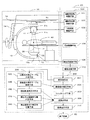
図1は、本発明を適用したC型アーム方式のコーンビームX線CT装置の概略構成を示すブロック図である。図2は、画像歪み補正テーブルの生成に使用されるホールチャート18を示す概念図である。図3は、前記ホールチャート18を2次元X線検出器のX線入射面に取り付ける際に生じる検出器取付け角を説明するための図である。
FIG. 1 is a block diagram showing a schematic configuration of a C-arm type cone beam X-ray CT apparatus to which the present invention is applied. FIG. 2 is a conceptual diagram showing a
図1のコーンビームX線CT装置1は、被検体40に対してX線を照射し、被検体40のX線透過画像を撮影してX線画像データを得る撮影部10と、撮影部10の各構成要素を制御したり、X線画像データに基づいて被検体40の3次元的X線CT像を再構成したりする制御演算部20とを備える。
The cone beam
(撮影部10)
撮影部10は、被検体40を載せる寝台17と、寝台17に載せられた被検体40にX線を照射するX線源11、X線源11に対向する位置に設置され、被検体40を透過したX線を検出することによりX線画像データを出力する2次元X線検出器12と、X線源11及び2次元X線検出器12を機械的に接続するC型アーム13とを備える。また撮影部10は、C型アーム13を保持するC型アーム保持体14と、C型アーム保持体14を天井に取り付ける天井支持体15と、天井支持体15を図1の状態で、前後左右の2次元方向に移動可能に支持する天井レール16とを備える。
(Shooting unit 10)
The
X線源11は、X線を発生するX線管11tと、X線管11tからのX線照射の方向を円錐または四角錐状に制御するコリメータ11cとを備える。
The
2次元X線検出器12は、X線透過像を可視光像に変換するX線イメージインテンシファイア12iと、X線イメージインテンシファイア12iによる可視光像を撮影するテレビカメラ12cとを備える。なお本実施の形態では、2次元X線検出器12は、X線イメージインテンシファイア12i及びテレビカメラ12cを備えるが、2次元X線検出器12は、フラットパネルディテクター(FPD)であってもよい。またその形状は円形、方形等のいかなる形状であってもよい。そして、2次元X線検出器12はその検出器素子列が回転中心軸31に平行(0°)あるいは90°の角度をなして設置される。例えば、2次元X線検出器12として長方形のフラットパネルディテクター(FPD)を用いる場合、その長辺を回転中心軸と90°の角度をなして設置すると胸部、腹部等、大視野の断面像の撮影に適合するし、長辺を回転中心軸と平行(0°)の角度をなして設置すると、頭頸部、四肢等の撮影に有用である。2次元X線検出器12は、その検出器素子列が、回転中心軸31に対し所定の基準角度だけ手動もしくは電動で回転できるようになっていてもよい。
The two-
上記C型アーム13は、被検体40の撮影に際して、所定の投影角度毎に回転中心軸31を中心として回転移動する。これにより、上記X線源11及び2次元X線検出器12は、ほぼ同一の円軌道上で回転移動しながら、X線撮影を行う。この回転移動については、画像再構成演算に使用される幾何学パラメータが存在する。すなわち、C型アーム13が回転移動することにより、X線源11と2次元X線検出器12とが描く円軌道を含む面である回転軌道面(ミッドプレーン)30と、回転中心軸31、及び検出器取付け角の基準角度(0°あるいは90°)からのずれである。
The C-
これらの幾何学パラメータは、原理的には、撮影部10の設計データから定まるものであるが、実際的には撮影部10の製作誤差や部材の変形に起因して、個々のコーンビームX線CT装置1に固有の値となる。
These geometric parameters are determined in principle from the design data of the
(制御演算部20)
制御演算部20は、撮影部10を制御する撮影部制御手段100と、撮影部10が出力したX線画像データを収集して格納する画像収集手段110と、収集されたX線画像データに基づいて3次元的X線CT像を再構成する再構成手段200と、撮影部10の機械的製作上の誤差を数値的に表わし、再構成手段200における3次元再構成の際に補正データとして用いる幾何学パラメータを求めるための幾何学パラメータ計算手段300とを備える。更に、再構成手段200で生成した3次元的X線CT像を表示する画像表示手段210を備える。
(Control arithmetic unit 20)
The
撮影部制御手段100は、C型アーム13が、回転中心軸31の回りを回転する(以下、「プロペラ回転」という。)回転移動を制御する撮影系回転制御手段101と、天井支持体15の天井レール16上での位置を制御してC型アーム13の被検体40に対する位置を2次元的に制御する撮影系位置制御手段102とを備える。更に撮影部制御手段100は、X線管11tに流す管電流のON、OFFなどを制御するX線照射制御手段103と、寝台17の位置を制御して被検体40の位置を調整するための寝台制御手段104と、2次元X線検出器12によるX線透過像の撮影を制御する検出系制御手段105とを備える。
The imaging
(再構成手段200)
再構成手段200は、前処理手段201と、画像歪み補正手段202と、フィルタリング手段203と、逆投影手段204とを備える。
(Reconstruction means 200)
The
前処理手段201は、画像収集手段110が収集したX線画像データをX線吸収係数の分布像に変換するための手段である。本実施の形態では先ず、被検体40及び寝台17を撮影視野内に配置しない状態で予め撮影された空気のX線透過像の各画素データに対して自然対数変換演算を施す。次に被検体40を寝台17に載せた状態で撮影したX線透過画像の各画素データに対して自然対数変換演算を施す。上記2つのX線透過画像の差分を取ることにより、被検体40及び寝台17のX線吸収係数の分布像を得る。
The preprocessing means 201 is means for converting the X-ray image data collected by the image collection means 110 into an X-ray absorption coefficient distribution image. In the present embodiment, first, a natural logarithmic transformation calculation is performed on each pixel data of an X-ray transmission image of air that has been captured in advance without the subject 40 and the
画像歪み補正手段202は、前処理手段201が生成したX線吸収係数の分布像の画像歪みを補正する。この画像歪みは、X線イメージインテンシファイア12iによってX線透過像を可視光像に変換する際に生ずる画像歪みであり、後述する画像歪み補正テーブル格納手段330により格納されている画像歪み補正テーブルを用いて、前処理手段201で得られたX線吸収係数の分布像の画像歪みを補正する。
The image
フィルタリング手段203は、X線CT画像再構成におけるフィルタリング処理を行う。
The
逆投影手段204は、フィルタリング処理後のX線画像データに基づいて逆投影演算を行う手段であり、3次元的X線CT像を生成する。
The
(幾何学パラメータ計算手段300)
幾何学パラメータ計算手段300は、再構成手段200で画像再構成を行う際に必要となる幾何学パラメータを算出する手段である。幾何学パラメータ計算手段300が扱う幾何学パラメータは、回転軌道面30と、回転中心軸31と、X線イメージインテンシファイア12iによる画像歪み、及び2次元X線検出器12の取付け角である。図1における回転軌道30と回転中心軸31、X線イメージインテンシファイア12iによる画像の歪み、それと後述する検出器取付け補正角である。これらの幾何学パラメータを算出するために、幾何学パラメータ計算手段300は、画像歪み補正テーブル生成手段320と、画像歪み補正テーブル格納手段330と、回転軌道面算出手段350と、回転中心軸投影位置計算手段370と、検出器取付け補正角計算手段380とを備える。上述した幾何学パラメータ計算手段300の各構成要素については、後述する。
(Geometric parameter calculation means 300)
The geometric
画像歪み補正テーブル生成手段320は、上述の画像歪み補正手段202で使用する画像歪み補正テーブルを生成する。画像歪み補正テーブル生成手段320は、図2に示すホールチャート18を用いて画像歪み補正テーブルを生成する。図2のホールチャート18は、X線に対する吸収の大きな材料で形成した板材に、格子状配列で多数の小さなホール18hを穿設して形成されている。画像歪み補正テーブルを生成するには、まず、X線イメージインテンシファイア12iの前面にホールチャート18を固定し、このホールチャート18のX線投影像(以下「ホールチャート歪み投影像」という。)を撮影する。次に、前処理手段201が、ホールチャート歪み投影像に前処理を行う。そして、ホールチャート歪み投影像における各ホール18hの投影位置を検出する。次に、ホールチャート18が歪みなくX線入射面に投影された場合を仮想した各ホール18hの仮想投影位置を演算する。そして、検出した各ホール18hの投影位置が、仮想投影位置に一致するように変換する計算をホール18h毎に行い、画像歪み補正テーブルを生成する。
The image distortion correction
画像歪み補正テーブル格納手段330は、画像歪み補正テーブル生成手段320で生成した画像歪み補正テーブルを磁気ディスク等に格納する。そして、画像歪み補正手段202がX線透過像の歪みを補正する際に、格納した画像歪み補正テーブルを読み出す。
The image distortion correction
回転軌道面算出手段350は、X線源の焦点の軌道を含む平面である回転軌道面30の2次元X線透過像上の座標を算出する手段である。これは例えば、棒状の支持体にX線吸収係数の大きい小金属球を複数個入れたファントムを回転中心軸に平行に配置して、回転撮影を行い、その金属球が2次元X線透過像上に描く楕円軌道を利用して求めることができる。
The rotational trajectory plane calculating means 350 is a means for calculating coordinates on the two-dimensional X-ray transmission image of the
コーンビームX線CT装置1は、図4及び図5に示すように、円柱形もしくは中空のパイプ状ファントム50のX線透過画像(以下「ファントム投影像」という。)を撮影し、ファントムX線画像データを出力する。
As shown in FIGS. 4 and 5, the cone beam
回転中心軸投影位置計算手段370は、ファントム投影像の再構成演算から、回転中心軸の2次元X線透過像上への投影座標(以下「回転中心軸投影位置」という。)を算出する手段である。 The rotation center axis projection position calculation means 370 calculates the projection coordinates on the two-dimensional X-ray transmission image of the rotation center axis (hereinafter referred to as “rotation center axis projection position”) from the reconstruction calculation of the phantom projection image. It is.
検出器取付け補正角計算手段380は、2次元X線検出器12の画像上での座標軸と、実際の回転中心軸との角度の差(検出器取付け補正角)を算出する手段である。
The detector attachment correction angle calculation means 380 is a means for calculating a difference (detector attachment correction angle) between the coordinate axis on the image of the two-
図3を用い検出器取付け角について説明する。32は回転中心軸31の投影、30は回転軌道面である。22はホールチャート18に固定された縦軸、21はホールチャート18の横軸であり、各々、回転中心軸31の投影32、回転軌道面30から角度b(24)だけ傾いて取り付いている。24を検出器取付け角とよび、角度b(24)がゼロでないと、画像歪み補正手段202で画像歪み補正後の画像は角度bだけ回転する。この回転角bを検出器取付け補正角計算手段380で求め、X線画像を検出器取付け角bとは逆方向に回転してこれを補正する。ただし、本実施の形態ではX線撮像系としてX線イメージインテンシファイア12i及びテレビカメラ12cを用いたが、TFT素子等を用いた2次元X線検出器に置き換える場合には、X線検出器の取付け角度のずれが角度bになる。
The detector mounting angle will be described with reference to FIG. 32 is a projection of the
上記のC型アーム方式コーンビームX線CT装置1の仕様例は次のとおりである。X線管11tと回転中心軸31との距離は800mm、回転中心軸31と2次元X線検出器12のX線入力面、すなわちX線イメージインテンシファイア12iのX線入射面との距離は400mm、X線イメージインテンシファイア12iのX線入射面の大きさは400mm、画像サイズは1024×1024(走査線数)である。そして2次元X線検出器12のピッチは0.4mmである。
A specification example of the C-arm type cone beam
撮影系回転制御手段101は、被検体40の頭部をC型アーム13側に向けて寝台17上に載置した状態で、2次元X線検出器12を、被検体40の左手の方向(−100°)から天井方向(0°)を通過し、被検体40の右手方向(+100°)まで移動させる(この時、X線源11は被検体40の右手方向(+100°)から寝台下方向を通過し、被検体40の左手方向(−100°)まで移動する)ことにより、200度の投影角度にわたって被検体40の2次元X線透過画像が撮影される。C型アーム13の回転速度の代表例は1秒当たり40度で、スキャン時間は5秒である。なお、被検体40の足部をC型アーム13側に向けて寝台17上に載置した状態で、2次元X線検出器12を、被検体40の右手の方向(−100°)から天井方向(0°)を通過し、被検体40の左手方向(+100°)まで移動させる場合もある。
The imaging system rotation control means 101 moves the two-
次に、本実施形態のC型アーム方式コーンビームX線CT装置1による撮影における動作の概要について説明する。
Next, an outline of operations in imaging by the C-arm type cone beam
先ず撮影系回転制御手段101はC型アーム13のプロペラ回転を開始する。回転加速期間を経たのち、X線照射制御手段103は、X線管11tにX線を照射させる。検出系制御手段105はテレビカメラ12cによる可視光像の撮像を開始する。X線管11tから照射されたX線は、被検体40を透過した後、X線イメージインテンシファイア12iへ入射する。X線透過像はX線イメージインテンシファイア12iで可視光像に変換され、テレビカメラ12cに取り込まれる。テレビカメラ12cは可視光像をビデオ信号に変換し、そのビデオ信号がA/D変換を経た後、デジタル信号からなる2次元のX線画像データとして画像収集手段110に記録される。テレビカメラ12cの撮影における標準走査モードは毎秒30フレーム、走査線数1024本である。回転角度ピッチは1.33度で、5秒間に150枚のX線透過画像を取得する。200度の回転撮影が完了すると、X線照射制御手段103はX線管11tのX線照射を終了し、撮影系回転制御手段101は回転を停止する。
First, the imaging system rotation control means 101 starts the propeller rotation of the C-
再構成手段200は、以上のような撮影に並行し、あるいは撮影終了後に画像収集手段110から2次元のX線画像データを読み出し、このX線画像データに基づいて画像再構成演算を行い、被検体40の3次元的X線CT像の再構成演算を行う。画像表示手段210は、3次元的X線CT像を、CRT装置や液晶ディスプレイ装置等からなる表示装置80に表示する。なお画像表示手段210は、画像収集手段110に記録されたX線画像データに基づき、2次元画像を表示してもよい。
The
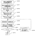
次に、図4及至6に基づいて、幾何学パラメータ計算手段300における処理の内容を説明する。図4は、円柱ファントム50が回転撮影される状態を説明するための概念図である。図5は、図4の状態を、寝台17からC型アーム13に向かって見た状態を示す概念図である。図6は、幾何学パラメータ計算手段300が、幾何学パラメータ計算処理を行う手順を示すフローチャートである。以下、図6のステップ順に説明をする。
Next, the contents of processing in the geometric parameter calculation means 300 will be described with reference to FIGS. FIG. 4 is a conceptual diagram for explaining a state in which the
(ステップS300)
幾何学パラメータ計算処理を開始する(S300)。
(Step S300)
The geometric parameter calculation process is started (S300).
(ステップS310)
ホールチャート18をX線イメージインテンシファイア12iのX線入射面に固定して回転撮影を行い、画像収集手段110により各投影角度におけるホールチャート歪み投影像の収集を行う。収集するホールチャート歪み投影像は、本実施の形態の場合であれば上述のように150枚になる。
(Step S310)
The
(ステップS320)
画像歪み補正テーブル生成手段320は、ステップS310で得られた150枚のホールチャート歪み投影像に基づいて、画像歪み補正テーブルを生成する。
(Step S320)
The image distortion correction
(ステップS330)
画像歪み補正テーブル格納手段330は、ステップS320で生成計算された画像歪み補正テーブルを格納する。
(Step S330)
The image distortion correction
(ステップS340)
小金属球が複数個入った棒状ファントムの回転撮影を行い、画像収集手段110により金属球ファントムのX線透過画像を収集する。
(Step S340)
The rod-shaped phantom containing a plurality of small metal spheres is rotated and an X-ray transmission image of the metal sphere phantom is collected by the image collecting means 110.
(ステップS350)
ステップS340で収集された金属球ファントムのX線透過画像から、X線透過画像内の小金属球が描く楕円軌道を求め、回転軌道面の2次元X線透過像上の座標を決定する。
(Step S350)
From the X-ray transmission image of the metal sphere phantom collected in step S340, an elliptical orbit drawn by the small metal sphere in the X-ray transmission image is obtained, and the coordinates on the two-dimensional X-ray transmission image of the rotating orbit plane are determined.
(ステップS360)
円柱ファントム50の回転撮影を行う。図4に示すように、ファントム保持体50aを寝台17上に載置する。そして、ファントム保持体50aは、図4及び図5に示すように、円柱ファントム50を回転中心軸31にできるだけ近い位置に、寝台17から突出させて載置させる。そして、X線源11及び2次元X線検出器12は、円柱ファントム50の回転撮影を行い、円柱ファントム50のX線透過像を撮影し、ファントムX線画像データを出力する。この円柱ファントム50のX線透過像には、円柱ファントム50の透過像であるファントム投影像が含まれる。画像収集手段110は、ファントムX線画像データを収集する。円柱ファントム50の撮影が終了すると、円柱形ファントム50及び円柱ファントム保持体50aは、寝台17上から取り除かれる。
(Step S360)
The
(ステップS370)
回転中心軸投影位置計算手段370は、ステップS360で収集されたファントムX線画像データに含まれるファントム投影像を用い、3次元的X線CT像を結像するために基準となるような回転中心軸投影パラメータを決定する。計算の具体的な処理の詳細は、図7乃至図12に基づいて後述する。なお、ステップS370では、回転軌道面(ミッドプレーン)30に限定したファントムX線画像データを用いた処理を行えば十分であり、こうすることで演算量を少なくすることができる。
(Step S370)
The rotation center axis projection position calculation means 370 uses the phantom projection image included in the phantom X-ray image data collected in step S360 and uses the rotation center as a reference for forming a three-dimensional X-ray CT image. Determine axial projection parameters. Details of specific processing of the calculation will be described later with reference to FIGS. In step S370, it is sufficient to perform processing using the phantom X-ray image data limited to the rotation orbit plane (midplane) 30. By doing so, the amount of calculation can be reduced.
(ステップS380)
ステップS360で収集された円柱ファントム50のX線透過像から、検出器取付け補正角計算手段380により、検出器取付け補正角を算出する。なお、ステップS380はステップS370と異なり、回転軌道面から離れた面で円柱ファントム50の再構成像を生成する。
(Step S380)
A detector mounting correction
ステップS350、S370、及びS380において算出された幾何学パラメータは、逆投影手段204において3次元的X線CT像を結像させるのに用いられる。
The geometric parameters calculated in steps S350, S370, and S380 are used to form a three-dimensional X-ray CT image in the
次に、図7乃至図12に基づいて、回転中心軸投影位置計算手段370と、検出器取付け補正角計算手段380の詳細について説明する。図7は、回転中心軸の投影パラメータが+u方向に誤差を持つ場合に、回転の前半の投影データから再構成される円柱ファントムの再構成断面について示した図である。図8は、回転中心軸の投影パラメータが+u方向に誤差を持つ場合に、回転の後半の投影データから再構成される円柱ファントムの再構成断面について示した図である。図9は、回転中心軸の投影パラメータが+u方向に誤差を持つ場合に、全回転撮影の投影データから再構成される円柱ファントムの再構成断面について示した図である。図10は、回転中心軸の投影パラメータが−u方向に誤差を持つ場合に、全回転撮影の投影データから再構成される円柱ファントムの再構成断面について示した図である。図11は、本発明の実施の形態における回転中心軸投影位置計算手段370が、回転中心軸投影位置計算処理を行う手順を示すフローチャートである。図12は、本発明の実施の形態における検出器取付け補正角計算手段380が、検出器取付け補正角計算処理を行う手順を示すフローチャートである。
Next, details of the rotation center axis projection position calculation means 370 and the detector mounting correction angle calculation means 380 will be described with reference to FIGS. FIG. 7 is a diagram showing a reconstructed cross section of a cylindrical phantom reconstructed from projection data in the first half of rotation when the projection parameter of the rotation center axis has an error in the + u direction. FIG. 8 is a diagram showing a reconstructed section of a cylindrical phantom reconstructed from projection data in the latter half of the rotation when the projection parameter of the rotation center axis has an error in the + u direction. FIG. 9 is a diagram showing a reconstructed cross section of a cylindrical phantom reconstructed from projection data of full rotation shooting when the projection parameter of the rotation center axis has an error in the + u direction. FIG. 10 is a diagram showing a reconstructed cross section of a cylindrical phantom reconstructed from projection data of full rotation imaging when the projection parameter of the rotation center axis has an error in the −u direction. FIG. 11 is a flowchart illustrating a procedure in which the rotation center axis projection
まず、図7乃至図10に基づいて、回転中心軸31の初期位置が異なっている場合に得られるファントム再構成像53について説明する。
First, a
分かりやすくするため、図7に回転の前半の投影データから再構成像が生成される様子、図8に回転の後半の投影データから再構成像が生成される様子を示す。図7及び図8は、回転中心軸51の投影位置を幾何学的に正しい値52よりもu軸方向に大きい値で再構成を行った場合を示す。また図7及び図8は、被検体40の足方向(すなわち寝台17からC型アーム13に向かって)からみたもので、簡単のためX線イメージインテンシファイア12i及びテレビカメラ12cのみを示し、他は省略した。X線イメージインテンシファイア12i及びテレビカメラ12cは被検体40の左手の方向から、天井の方向を通過し、被検体40の右手の方向まで移動する。
For easy understanding, FIG. 7 shows a state in which a reconstructed image is generated from the projection data in the first half of the rotation, and FIG. 8 shows a state in which a reconstructed image is generated from the projection data in the second half of the rotation. 7 and 8 show a case where the projection position of the
図7に示すように、回転の前半の投影データからの再構成断面像54は、正しい大きさにならず、再構成断面像54が示すファントム半径は小さくなる。そして縮小した再構成ファントムの半径は、幾何学的に正しい回転中心軸で計測されるファントム端の投影位置51と、現在使用している回転中心軸で計測されるファントム端の投影位置52との差に等しくなる。
As shown in FIG. 7, the reconstructed
一方、図8に示す回転の後半の投影データからの再構成断面像55のファントム半径は大きくなる。この場合、増大した再構成ファントムの半径は、幾何学的に正しい回転中心軸で計測されるファントム端の投影位置51と、現在使用している回転中心軸で計測されるファントム端の投影位置52との差に等しくなる。
On the other hand, the phantom radius of the reconstructed
図9に、回転中心軸の投影位置を幾何学的に正しい値よりもu軸方向に大きい値で再構成を行った場合に、実際に得られる再構成像56を、図10に、回転中心軸の投影位置を幾何学的に正しい値よりもu軸方向に小さい値で再構成を行った場合に、得られる再構成像57を示す。ファントム再構成断面は円形とならず、左右にアンバランスなものとなる。なお図9及び図10は分かりやすくするために模式的にしたものであり、実際は左右データの境界が突き出ることはなく、滑らかにつながった再構成像が得られる。
FIG. 9 shows a
次に、図11に基づいて、回転中心軸投影位置計算手段370が、回転中心軸投影位置を決定する手順を詳細に説明する。なお上述したように、以下の処理では、回転中心軸投影位置計算手段370では、回転軌道面(ミッドプレーン)30に限定した投影データを用い、演算処理を行えば十分である。
Next, a procedure in which the rotation center axis projection
(ステップS370)
回転中心軸投影位置計算処理を開始する(S370)。
(Step S370)
The rotation center axis projection position calculation process is started (S370).
(ステップS371)
回転中心軸投影位置(以下、centerと称す)を初期位置(設計位置)に設定する。
(Step S371)
A rotation center axis projection position (hereinafter referred to as center) is set as an initial position (design position).
(ステップS372)
前処理手段201は、ステップS360で収集されたファントムX線画像データの前処理を行う。
(Step S372)
The
(ステップS373)
画像歪み補正手段202は、ステップS372で前処理を行ったファントムX線画像データに対して画像歪み補正処理を行う。
(Step S373)
The image
(ステップS374)
フィルタリング手段203は、ステップS373で画像歪み補正処理を行ったファントムX線画像データについて、フィルタリング処理を行う。
(Step S374)
The
(ステップS375)
逆投影手段204は、ステップS374でフィルタリング処理を行ったファントムX線画像データについて、回転中心軸投影位置(center)の値で、回転軌道面30上の逆投影演算を行い、ファントム再構成像53を生成する。
(Step S375)
The
(ステップS376)
ステップS375で生成したファントム再構成像53の、左半分のファントム再構成半径(rA)、右半分のファントム再構成半径(rB)を算出する。ここで、再構成半径の算出には、例えば円曲線の方程式へのパラメータフィッテングの方法などを使用することができる。
(Step S376)
The left half phantom reconstruction radius (rA) and the right half phantom reconstruction radius (rB) of the
(ステップS377)
ステップS376で算出した左右のファントム再構成半径(rA、rB)が等しいと見なせるかを判定する。再構成半径Raと再構成半径rBとの差がゼロと見なせれば現在のcenterの値を出力して終了する(S379)。ゼロと見なせなければステップS378へ移行する。
(Step S377)
It is determined whether the left and right phantom reconstruction radii (rA, rB) calculated in step S376 can be considered equal. If the difference between the reconstruction radius Ra and the reconstruction radius rB can be regarded as zero, the current center value is output and the process ends (S379). If it cannot be regarded as zero, the process proceeds to step S378.
(ステップS378)
ステップS377で弧の半径がゼロと見なせなかった場合、図9の場合か図10の場合であるかを判断し、それに応じてcenterの値が正しくなるように加減算して補正する。そして、ステップS375からの処理を再度行う。
(Step S378)
If the radius of the arc cannot be regarded as zero in step S377, it is determined whether it is the case of FIG. 9 or FIG. 10, and correction is performed by adding / subtracting so that the center value becomes correct accordingly. Then, the processing from step S375 is performed again.
次に図12を用いて、検出器取付け補正角計算手段380が、検出器取付け補正角を決定する手順を詳細に説明する。 Next, with reference to FIG. 12, a procedure in which the detector mounting correction angle calculation means 380 determines the detector mounting correction angle will be described in detail.
(ステップS380)
検出器取付け補正角計算処理を開始する(S380)。
(Step S380)
The detector mounting correction angle calculation process is started (S380).
(ステップS381)
検出器取付け補正角(以下、twistと称す)を初期位置(設計位置、例えば0°)に設定する。
(Step S381)
A detector mounting correction angle (hereinafter referred to as twist) is set to an initial position (design position, for example, 0 °).
(ステップS382)
前処理手段201は、ステップS372と同様、ステップS360で収集されたファントムX線画像データの前処理を行う。
(Step S382)
The
(ステップS383)
画像歪み補正手段202は、ステップS373と同様、ステップS382で前処理を行ったファントムX線画像データに対して画像歪み補正処理を行う。
(Step S383)
Similar to step S373, the image
(ステップS384)
フィルタリング手段203は、ステップS374と同様、ステップS383で画像歪み補正処理を行ったファントムX線画像データについて、フィルタリング処理を行う。
(Step S384)
The
(ステップS385)
逆投影手段204は、ステップS384でフィルタリング処理を行ったファントムX線画像データについて、検出器取付け補正角(twist)、及びステップS380で決定した回転中心軸投影位置(center)の値で、回転軌道面30から離れた1つまたは複数の面での逆投影演算を行い、ファントム再構成像53を生成する。
(Step S385)
The
(ステップS386)
ステップS385で生成したファントム再構成像53の、左半分のファントム再構成半径(rA)、右半分のファントム再構成半径(rB)を算出する。
(Step S386)
The left half phantom reconstruction radius (r A ) and the right half phantom reconstruction radius (r B ) of the
(ステップS387)
ステップS387で算出した左右のファントム再構成半径(rA、rB)が等しいと見なせるかを判定する。ファントム再構成半径rAと、ファントム再構成半径rBとの差がゼロと見なせれば現在のtwistの値を出力して終了する(S389)。ゼロと見なせなければステップS388へ移行する。
(Step S387)
It is determined whether the left and right phantom reconstruction radii (rA, rB) calculated in step S387 can be regarded as equal. If the difference between the phantom reconstruction radius rA and the phantom reconstruction radius rB can be regarded as zero, the current twist value is output and the process ends (S389). If it cannot be regarded as zero, the process proceeds to step S388.
(ステップS388)
ステップS387で弧の半径がゼロと見なせなかった場合、図9の場合か図10の場合であるかを判断し、それに応じてcenterの値が正しくなるように加減算して補正する。そして、ステップS385からの処理を再度行う。
(Step S388)
If the radius of the arc cannot be regarded as zero in step S387, it is determined whether it is the case of FIG. 9 or FIG. 10, and correction is performed by adding / subtracting so that the center value becomes correct accordingly. Then, the processing from step S385 is performed again.
次に、本発明の第二の実施形態について図13乃至図15を用いて説明する。上記、第一の実施形態では、回転中心軸投影位置計算手段370が回転中心軸の投影位置を算出した後に、検出器取付け補正角計算手段380による補正角度の算出を実施するが、第二の実施形態は、回転中心軸投影位置計算手段370及び検出器取付け補正角計算手段380と同等の処理を一度に施すものである。図13は、第二の実施の形態におけるC型アーム方式のコーンビームX線CT装置1の概略構成を示すブロック図である。図14は、第二の実施の形態を説明するためのフローチャート、図15は、図14の処理から回転中心軸投影位置と検出器取付け補正角が求まる様子を示す図である。図15左側の楕円図は、回転中心軸投影位置と検出器取付け角、両方の補正が正しく行われないで円柱ファントム50を再構成したときに得られる再構成断面像、及び検出器取付け角bがゼロでないことにより再構成断面がスライス方向に変化していく様子を模式的に示す斜図である。この図では、3スライスの再構成断面像の斜図を示すが、回転中心軸投影位置と検出器取付け角、両方の補正が正しく行われない場合、左右アンバランスがスライス方向に連続的に変化していく円柱体として再構成される様子を示している。図15の特別な場合として、検出器取付け角の補正のみが正しく行われている場合には、左右アンバランスがスライス位置によらず一定な再構成断面像が得られる。
Next, a second embodiment of the present invention will be described with reference to FIGS. In the first embodiment, after the rotation center axis projection
図13に示すように、第二の実施の形態に係るX線CT装置1の幾何学パラメータ計算手段300は、第一の実施の形態の幾何学パラメータ300における回転中心軸投影位置計算手段370、及び検出器取付け補正角計算手段380に代えて、回転中心軸投影位置及び検出器取付け補正角計算手段470を備える。その他の構成は、第一の実施の形態に係るX線CT装置と同様である。
As shown in FIG. 13, the geometric parameter calculation means 300 of the
図14に基づいて、第二の実施形態における、回転中心軸投影位置及び検出器取付け補正角計算処理手段470について説明する。 Based on FIG. 14, the rotation center axis projection position and detector mounting correction angle calculation processing means 470 in the second embodiment will be described.
(ステップS470)
回転中心軸投影位置及び検出器取付け補正角計算処理を開始する(S470)。
(Step S470)
The rotation center axis projection position and detector mounting correction angle calculation processing is started (S470).
(ステップS471)
ステップS371と同様、回転軌道面での回転中心軸投影位置CMを初期位置(設計位置)に設定する。
(Step S471)
As in step S371, the rotation center axis projection position CM on the rotation orbit plane is set to the initial position (design position).
(ステップS472)
前処理手段201は、ステップS372と同様、ステップS360で収集されたファントムX線画像データの前処理を行う。
(Step S472)
The
(ステップS473)
画像歪み補正手段202は、ステップS373と同様、ステップS472で前処理を行ったファントムX線画像データに対して画像歪み補正処理を行う。
(Step S473)
Similar to step S373, the image
(ステップS474)
フィルタリング手段203は、ステップS374と同様、ステップS473で画像歪み補正処理を行ったファントムX線画像データについて、フィルタリング処理を行う。
(Step S474)
The
(ステップS475)
逆投影手段204は、ステップS474でフィルタリング処理を行ったファントムX線画像データについて、回転軌道面に平行な複数個の断面(回転軌道面からの距離をDとする)について逆投影演算を行い、ファントム再構成像53を生成する。
(Step S475)
The
(ステップS476)
ステップS475で生成した複数個のファントム再構成像53の、左半分のファントム再構成半径(rA)、右半分のファントム再構成半径(rB)を算出する。再構成半径の算出には、第一の実施形態と同様、円曲線の方程式へのパラメータフィッテングの方法などを使用することができる。
(Step S476)
The left half phantom reconstruction radius (r A ) and the right half phantom reconstruction radius (r B ) of the plurality of
(ステップS477)
ステップS476で算出した左右のファントム再構成半径(rA、rB)から、各再構成断面について回転中心軸投影位置の補正量C(D)を算出する。
(Step S477)
From the left and right phantom reconstruction radii (r A , r B ) calculated in step S476, the correction amount C (D) of the rotation center axis projection position is calculated for each reconstruction section.
(ステップS478)
ステップS477で算出した回転中心投影位置の補正量C(D)を用い、図15に示すように、回転中心軸投影位置CMと検出器取付け角bを関係式:C(D)=CM+D・tanbへのフィッティングにより決定する。決定した回転中心軸投影位置CMと検出器取付け角bを出力して終了する(S479)。
(Step S478)
Using the correction amount C (D) of the rotation center projection position calculated in step S477, as shown in FIG. 15, the rotation center axis projection position CM and the detector mounting angle b are expressed by a relational expression: C (D) = CM + D · tanb Determine by fitting to. The determined rotation center axis projection position CM and detector mounting angle b are output and the process ends (S479).
以上説明した幾何学パラメータ処理計算手段300により、3次元的X線CT像を生成し表示するコーンビームX線CT装置1において、鮮明な3次元的X線CT像を生成するための幾何学パラメータ、回転中心軸31の投影位置、検出器取付け角24を求めることができる。
In the cone beam
以上説明したように、本実施の形態の幾何学パラメータ計算手段を搭載する事により、C型アーム等の回転撮影から収集される2次元X線像から3次元的X線CT像を生成するコーンビームX線CT装置において、回転中心軸及び検出器取付け角が正しい設計値から変位した場合にも、鮮明な3次元的X線CT像を生成し表示することができる。これにより、頭部、腹部等の造影撮影、並びに歯顎、腰椎、四肢等の整形分野の診断性能を向上させることができる。 As described above, a cone that generates a three-dimensional X-ray CT image from a two-dimensional X-ray image collected from rotational imaging of a C-type arm or the like by mounting the geometric parameter calculation means of the present embodiment. In the beam X-ray CT apparatus, a clear three-dimensional X-ray CT image can be generated and displayed even when the rotation center axis and detector mounting angle are displaced from correct design values. As a result, contrast imaging of the head, abdomen, and the like, and diagnostic performance in the field of shaping of the teeth, jaws, lumbar vertebrae, and limbs can be improved.
なお本発明は上記実施の形態に限定されるものではなく、本発明の要旨を逸脱しない範囲で種々に変形することができる。例えば、上記実施の形態では、2次元X線検出器としてX線イメージインテンシファイアとテレビカメラの組み合わせで形成するようにしていたが、これに代えて、例えばフラットパネルディテクター(FPD)を用いて2次元X線検出器を構成するようにしてもよい。また本発明はC型アーム方式以外のコーンビームX線CT装置にも適用可能であるし、回転撮影の全角度が200度以外の場合にも勿論、適用可能である。 In addition, this invention is not limited to the said embodiment, It can deform | transform variously in the range which does not deviate from the summary of this invention. For example, in the above embodiment, the two-dimensional X-ray detector is formed by a combination of an X-ray image intensifier and a TV camera. Instead, for example, a flat panel detector (FPD) is used. A two-dimensional X-ray detector may be configured. The present invention can also be applied to a cone beam X-ray CT apparatus other than the C-arm system, and of course, can also be applied to cases where the entire angle of rotational imaging is other than 200 degrees.
1…コーンビームX線CT装置、10…撮影部、11…X線源、11t…X線管、11c…コリメータ、12…2次元X線検出器、12i…X線イメージインテンシファイア、12c…テレビカメラ、13…C型アーム、14…C型アーム保持体、15…天井支持体、16…天井レール、17…寝台、18…ホールチャート、18h…ホール、20…制御演算部、21…ホールチャート18に固定された横軸、22…ホールチャート18に固定された縦軸、24…検出器取付け角、30…回転軌道面(ミッドプレーン)、31…回転中心軸、32…回転中心軸の投影、40…被検体、50…円柱ファントム、50a…ファントム保持体、51…幾何学的に正しい回転中心軸で計測されるファントム端の投影位置、52…現在使用している回転中心軸で計測されるファントム端の投影位置、53…ファントム再構成像、54…回転中心軸の投影パラメータが+u方向に誤差を持つ場合に、回転の前半の投影データから再構成される円柱ファントムの再構成断面、55…回転中心軸の投影パラメータが+u方向に誤差を持つ場合に、回転の後半の投影データから再構成される円柱ファントムの再構成断面、56…回転中心軸の投影パラメータが+u方向に誤差を持つ場合に、全回転撮影の投影データから再構成される円柱ファントムの再構成断面、57…回転中心軸の投影パラメータが−u方向に誤差を持つ場合に、全回転撮影の投影データから再構成される円柱ファントムの再構成断面、80…表示装置、100…撮影部制御手段、101…撮影系回転制御手段、102…撮影系位置制御手段、103…X線照射制御手段、104…寝台制御手段、105…検出系制御手段、110…画像収集手段、200…再構成手段、201…前処理手段、202…画像歪み補正手段、203…フィルタリング手段、204…逆投影手段、210…画像表示手段、300…幾何学パラメータ計算手段、320…画像歪み補正テーブル生成手段、330…画像歪み補正テーブル格納手段、350…回転軌道面算出手段、370…回転中心軸投影位置計算手段、380…検出器取付け補正角計算手段
DESCRIPTION OF
Claims (3)
前記X線源に対向して配置され、前記被検体を透過した前記X線を検出して前記被検体のX線画像データを出力する2次元X線検出器と、
前記X線源及び前記2次元X線検出器を回転移動させるための回転手段と、
前記X線画像データに基づいて画像再構成演算を行なう逆投影手段を備えた画像処理装置と、
を備えたX線CT装置において、
前記画像処理装置は、
前記回転手段による回転移動により示される設計上の回転中心軸の位置と、前記回転手段による実際の回転移動により示される回転中心軸の位置と、の相対変位量を、前記設計上の回転中心軸の近傍に位置したファントムの再構成像の半径の差に基づいて算出する回転中心軸投影位置計算手段を備え、
前記逆投影手段は、前記相対変位量に基づいて前記X線画像データの修正を行い、画像を再構成する、
ことを特徴とするX線CT装置。 An X-ray source for irradiating the subject with X-rays;
A two-dimensional X-ray detector that is disposed opposite to the X-ray source, detects the X-ray transmitted through the subject, and outputs X-ray image data of the subject;
Rotating means for rotating the X-ray source and the two-dimensional X-ray detector;
An image processing apparatus comprising back projection means for performing image reconstruction calculation based on the X-ray image data;
In an X-ray CT apparatus equipped with
The image processing apparatus includes:
The relative amount of displacement between the position of the design rotation center axis indicated by the rotation movement by the rotation means and the position of the rotation center axis indicated by the actual rotation movement by the rotation means is expressed as the design rotation center axis. A rotation center axis projection position calculation means for calculating based on the difference in radius of the reconstructed image of the phantom located in the vicinity of
The back projection means corrects the X-ray image data based on the relative displacement amount, and reconstructs an image;
An X-ray CT apparatus characterized by that.
前記X線源に対向して配置され、前記被検体を透過した前記X線を検出して前記被検体のX線画像データを出力する2次元X線検出器と、
前記X線源及び前記2次元X線検出器を回転移動させるための回転手段と、
前記X線画像データに基づいて画像再構成演算を行なう逆投影手段を備えた画像処理装置と、
を備えたX線CT装置において、
前記2次元X線検出器は、前記回転手段の回転移動により示される設計上の回転中心軸に対して、設計上は所定の基準角度をなして取り付けられ、
前記画像処理装置は、
前記設計上の回転中心軸及び前記2次元X線検出器の回転軌道面の近傍に位置したファントムの再構成像の半径の差と、前記2次元X線検出器の回転軌道面から前記ファントムまでの距離とに基づいて、前記設計上の回転中心軸の位置と前記回転手段による実際の回転移動を示す回転中心軸の位置との相対変位量と、前記設計上の所定の基準角度と前記設計上の回転中心軸に対する前記2次元X線検出器の実際の取り付け角度との角度差を修正するために必要な補正角度と、を算出する幾何学パラメータ計算手段を備え、
前記逆投影手段は、前記相対変位量及び前記補正角度に基づいて前記X線画像データの修正を行い、画像を再構成する、
ことを特徴とするX線CT装置。 An X-ray source for irradiating the subject with X-rays;
A two-dimensional X-ray detector that is disposed opposite to the X-ray source, detects the X-ray transmitted through the subject, and outputs X-ray image data of the subject;
Rotating means for rotating the X-ray source and the two-dimensional X-ray detector;
An image processing apparatus comprising back projection means for performing image reconstruction calculation based on the X-ray image data;
In an X-ray CT apparatus equipped with
The two-dimensional X-ray detector is attached with a predetermined reference angle in design with respect to a design rotation center axis indicated by the rotational movement of the rotation means,
The image processing apparatus includes:
The difference in radius of the reconstructed image of the phantom located in the vicinity of the design rotation center axis and the rotation orbit plane of the two-dimensional X-ray detector, and from the rotation orbit plane of the two-dimensional X-ray detector to the phantom Based on the distance of the design, the relative displacement amount between the position of the design rotation center axis and the position of the rotation center axis indicating the actual rotational movement by the rotation means, the predetermined reference angle on the design, and the design A geometric parameter calculation means for calculating a correction angle required to correct an angle difference between the rotation angle of the two-dimensional X-ray detector and the actual mounting angle with respect to the upper rotation center axis;
The back projection means corrects the X-ray image data based on the relative displacement amount and the correction angle, and reconstructs an image;
An X-ray CT apparatus characterized by that.
前記ファントムは、前記寝台に載置される前記被検体の体軸方向に沿って配置された円柱状又は中空のパイプ状のファントムとして構成され、
前記幾何学パラメータ計算手段は、前記ファントムの前記体軸方向の位置毎に、前記ファントムの再構成像の径の差から前記設計上の回転中心軸の位置に対する前記実際の回転移動により示される回転中心軸の位置のシフト量を求め、前記位置毎に求めたシフト量を前記回転軌道面からの距離の関数としてフィッティングを行い、当該フィッティング結果から、前記相対変位量及び前記補正角度を算出する、
ことを特徴とする請求項2に記載のX線CT装置。 Further comprising a bed on which the subject is placed;
The phantom is configured as a cylindrical or hollow pipe-shaped phantom arranged along the body axis direction of the subject placed on the bed,
For each position of the phantom in the body axis direction, the geometric parameter calculation means is a rotation indicated by the actual rotational movement relative to the position of the designed rotation center axis from the difference in diameter of the reconstructed image of the phantom. Obtaining the shift amount of the position of the central axis, fitting the shift amount obtained for each position as a function of the distance from the rotational track surface, and calculating the relative displacement amount and the correction angle from the fitting result,
The X-ray CT apparatus according to claim 2 .
Priority Applications (1)
| Application Number | Priority Date | Filing Date | Title |
|---|---|---|---|
| JP2004322442A JP4610304B2 (en) | 2004-11-05 | 2004-11-05 | X-ray CT system |
Applications Claiming Priority (1)
| Application Number | Priority Date | Filing Date | Title |
|---|---|---|---|
| JP2004322442A JP4610304B2 (en) | 2004-11-05 | 2004-11-05 | X-ray CT system |
Publications (3)
| Publication Number | Publication Date |
|---|---|
| JP2006130060A JP2006130060A (en) | 2006-05-25 |
| JP2006130060A5 JP2006130060A5 (en) | 2007-12-13 |
| JP4610304B2 true JP4610304B2 (en) | 2011-01-12 |
Family
ID=36724099
Family Applications (1)
| Application Number | Title | Priority Date | Filing Date |
|---|---|---|---|
| JP2004322442A Expired - Fee Related JP4610304B2 (en) | 2004-11-05 | 2004-11-05 | X-ray CT system |
Country Status (1)
| Country | Link |
|---|---|
| JP (1) | JP4610304B2 (en) |
Families Citing this family (8)
| Publication number | Priority date | Publication date | Assignee | Title |
|---|---|---|---|---|
| JP2007130278A (en) * | 2005-11-11 | 2007-05-31 | Ge Medical Systems Global Technology Co Llc | X-ray ct apparatus |
| CN103961130B (en) * | 2006-09-25 | 2017-08-15 | 马佐尔机器人有限公司 | So that C-arm system adapts to the method to provide three-dimensional imaging information |
| JP5210726B2 (en) * | 2008-06-24 | 2013-06-12 | 株式会社東芝 | X-ray CT system |
| JP5661624B2 (en) * | 2008-08-13 | 2015-01-28 | コーニンクレッカ フィリップス エヌ ヴェ | Removal of ring artifacts due to mechanical alignment of 3D rotational X-ray scanner system |
| JP5537226B2 (en) * | 2010-03-31 | 2014-07-02 | 株式会社日立メディコ | Radiation imaging device |
| JP7242288B2 (en) * | 2018-12-25 | 2023-03-20 | キヤノンメディカルシステムズ株式会社 | Medical image diagnosis device and model learning device |
| CN116831607B (en) * | 2023-09-01 | 2023-12-01 | 赛诺威盛科技(北京)股份有限公司 | Correction device and correction method for medical imaging equipment and medical imaging equipment |
| CN117679060B (en) * | 2024-02-01 | 2024-06-21 | 赛诺威盛科技(北京)股份有限公司 | Method and system for correcting mechanical position of bulb tube based on thin disc die body |
Citations (3)
| Publication number | Priority date | Publication date | Assignee | Title |
|---|---|---|---|---|
| JPH09173330A (en) * | 1995-12-22 | 1997-07-08 | Hitachi Medical Corp | X-ray tomography apparatus |
| JP2000201918A (en) * | 1999-01-11 | 2000-07-25 | Hitachi Medical Corp | X-ray ct system and x-ray photographing method of x-ray image and phantom |
| JP2002336237A (en) * | 2001-05-18 | 2002-11-26 | Morita Mfg Co Ltd | X-ray image correction phantom, and x-ray image correction method and x-ray ct radiographic device using the phantom |
-
2004
- 2004-11-05 JP JP2004322442A patent/JP4610304B2/en not_active Expired - Fee Related
Patent Citations (3)
| Publication number | Priority date | Publication date | Assignee | Title |
|---|---|---|---|---|
| JPH09173330A (en) * | 1995-12-22 | 1997-07-08 | Hitachi Medical Corp | X-ray tomography apparatus |
| JP2000201918A (en) * | 1999-01-11 | 2000-07-25 | Hitachi Medical Corp | X-ray ct system and x-ray photographing method of x-ray image and phantom |
| JP2002336237A (en) * | 2001-05-18 | 2002-11-26 | Morita Mfg Co Ltd | X-ray image correction phantom, and x-ray image correction method and x-ray ct radiographic device using the phantom |
Also Published As
| Publication number | Publication date |
|---|---|
| JP2006130060A (en) | 2006-05-25 |
Similar Documents
| Publication | Publication Date | Title |
|---|---|---|
| JP5019879B2 (en) | X-ray CT apparatus, image processing program, and image processing method | |
| JP4537129B2 (en) | System for scanning objects in tomosynthesis applications | |
| JP2007181623A (en) | X-ray ct apparatus | |
| JP3548339B2 (en) | X-ray equipment | |
| JP4966120B2 (en) | X-ray angiography equipment | |
| JP4408664B2 (en) | Cone beam X-ray CT apparatus and phantom used therefor | |
| US20120307960A1 (en) | X-ray computed tomographic imaging apparatus and method for same | |
| JP3897925B2 (en) | Cone beam CT system | |
| JP2011152255A (en) | Reconstruction arithmetic unit, reconstruction arithmetic method, and x-ray ct apparatus | |
| JP3540916B2 (en) | 3D X-ray CT system | |
| US20110075798A1 (en) | Method for correcting truncated projection data | |
| JP4989473B2 (en) | Three-dimensional reproduction method and apparatus using an inclined configuration | |
| JP4610304B2 (en) | X-ray CT system | |
| JP2006204329A (en) | X-ray tomographic equipment | |
| JP4573593B2 (en) | X-ray image correction method and apparatus | |
| JP4884765B2 (en) | X-ray CT system | |
| JP2006326319A (en) | X-ray imaging system | |
| JP2007159878A (en) | X-ray ct apparatus and method of reconstructing x-ray ct image of the same | |
| JP4429709B2 (en) | X-ray tomography equipment | |
| JP2009279301A (en) | Cone beam x-ray ct system | |
| JP2008036272A (en) | Cone beam x-ray ct system | |
| JPWO2011055741A1 (en) | X-ray CT apparatus and X-ray CT imaging method | |
| JP5303154B2 (en) | X-ray CT system | |
| JP2006296926A (en) | X-ray imaging apparatus, image processing method, computer readable storage medium and program | |
| JP4421917B2 (en) | Cone beam X-ray CT system |
Legal Events
| Date | Code | Title | Description |
|---|---|---|---|
| A521 | Request for written amendment filed |
Free format text: JAPANESE INTERMEDIATE CODE: A523 Effective date: 20071025 |
|
| A621 | Written request for application examination |
Free format text: JAPANESE INTERMEDIATE CODE: A621 Effective date: 20071025 |
|
| RD02 | Notification of acceptance of power of attorney |
Free format text: JAPANESE INTERMEDIATE CODE: A7422 Effective date: 20090717 |
|
| RD04 | Notification of resignation of power of attorney |
Free format text: JAPANESE INTERMEDIATE CODE: A7424 Effective date: 20090721 |
|
| A977 | Report on retrieval |
Free format text: JAPANESE INTERMEDIATE CODE: A971007 Effective date: 20100408 |
|
| A131 | Notification of reasons for refusal |
Free format text: JAPANESE INTERMEDIATE CODE: A131 Effective date: 20100506 |
|
| A521 | Request for written amendment filed |
Free format text: JAPANESE INTERMEDIATE CODE: A523 Effective date: 20100630 |
|
| A131 | Notification of reasons for refusal |
Free format text: JAPANESE INTERMEDIATE CODE: A131 Effective date: 20100727 |
|
| A521 | Request for written amendment filed |
Free format text: JAPANESE INTERMEDIATE CODE: A523 Effective date: 20100916 |
|
| TRDD | Decision of grant or rejection written | ||
| A01 | Written decision to grant a patent or to grant a registration (utility model) |
Free format text: JAPANESE INTERMEDIATE CODE: A01 Effective date: 20101012 |
|
| A01 | Written decision to grant a patent or to grant a registration (utility model) |
Free format text: JAPANESE INTERMEDIATE CODE: A01 |
|
| A61 | First payment of annual fees (during grant procedure) |
Free format text: JAPANESE INTERMEDIATE CODE: A61 Effective date: 20101012 |
|
| FPAY | Renewal fee payment (event date is renewal date of database) |
Free format text: PAYMENT UNTIL: 20131022 Year of fee payment: 3 |
|
| R150 | Certificate of patent or registration of utility model |
Free format text: JAPANESE INTERMEDIATE CODE: R150 |
|
| LAPS | Cancellation because of no payment of annual fees |