JP3897925B2 - Cone beam CT system - Google Patents
Cone beam CT system Download PDFInfo
- Publication number
- JP3897925B2 JP3897925B2 JP02164799A JP2164799A JP3897925B2 JP 3897925 B2 JP3897925 B2 JP 3897925B2 JP 02164799 A JP02164799 A JP 02164799A JP 2164799 A JP2164799 A JP 2164799A JP 3897925 B2 JP3897925 B2 JP 3897925B2
- Authority
- JP
- Japan
- Prior art keywords
- ray
- image
- dimensional
- subject
- sharpness
- Prior art date
- Legal status (The legal status is an assumption and is not a legal conclusion. Google has not performed a legal analysis and makes no representation as to the accuracy of the status listed.)
- Expired - Fee Related
Links
- 230000005540 biological transmission Effects 0.000 claims description 53
- 230000001678 irradiating effect Effects 0.000 claims description 3
- 230000033001 locomotion Effects 0.000 description 164
- 238000005259 measurement Methods 0.000 description 145
- 238000000034 method Methods 0.000 description 60
- 238000001514 detection method Methods 0.000 description 47
- 238000012545 processing Methods 0.000 description 28
- 238000010586 diagram Methods 0.000 description 15
- 230000003287 optical effect Effects 0.000 description 14
- 230000008569 process Effects 0.000 description 14
- 238000004364 calculation method Methods 0.000 description 13
- 238000003384 imaging method Methods 0.000 description 11
- 230000000694 effects Effects 0.000 description 9
- 238000012937 correction Methods 0.000 description 8
- 238000010521 absorption reaction Methods 0.000 description 4
- 238000006243 chemical reaction Methods 0.000 description 4
- 238000009434 installation Methods 0.000 description 4
- 238000009877 rendering Methods 0.000 description 4
- 239000003550 marker Substances 0.000 description 3
- 238000007781 pre-processing Methods 0.000 description 3
- 230000008859 change Effects 0.000 description 2
- 238000007689 inspection Methods 0.000 description 2
- 230000007246 mechanism Effects 0.000 description 2
- 230000004044 response Effects 0.000 description 2
- 239000004065 semiconductor Substances 0.000 description 2
- 230000035945 sensitivity Effects 0.000 description 2
- 230000002159 abnormal effect Effects 0.000 description 1
- 238000003745 diagnosis Methods 0.000 description 1
- 238000005516 engineering process Methods 0.000 description 1
- 238000003709 image segmentation Methods 0.000 description 1
- 230000003252 repetitive effect Effects 0.000 description 1
- 238000004904 shortening Methods 0.000 description 1
- 229910001220 stainless steel Inorganic materials 0.000 description 1
- 239000010935 stainless steel Substances 0.000 description 1
- 239000000126 substance Substances 0.000 description 1
- 239000010409 thin film Substances 0.000 description 1
- 230000009466 transformation Effects 0.000 description 1
- WFKWXMTUELFFGS-UHFFFAOYSA-N tungsten Chemical compound [W] WFKWXMTUELFFGS-UHFFFAOYSA-N 0.000 description 1
- 229910052721 tungsten Inorganic materials 0.000 description 1
- 239000010937 tungsten Substances 0.000 description 1
- 230000000007 visual effect Effects 0.000 description 1
Images


Description
【0001】
【発明の属する技術分野】
本発明は、コーンビームCT装置に関し、特に、二次元X線画像検出装置を用いて、高分解能の三次元X線像を得ることに適用して有効な技術に関するものである。
【0002】
【従来の技術】
従来、X線を用いて被写体内部のX線吸収係数の分布を計測し、断層像を作成するX線CT装置があった。このX線CT装置では、対向配置されたX線源と1次元X線検出器とを被写体の全周に回転させながら被写体の透過X線像(投影データ)の撮影(計測)を行い、得られた投影データを再構成することにより断層像を得ていた。従来のX線CT装置を用いて三次元X線像を得る方法としては、多数の断層像を積み重ねる方法があった。しかし、多数の断層像を積み重ねる方法では、回転面に垂直な方向の解像度を回転面内の解像度と同等にするために、非常に長時間かつ多被曝の計測が必要であった。
【0003】
計測時間短縮と被曝低減のために、被写体を検出器の回転面に垂直な方向に移動しながらX線源と検出器を多数回にわたって回転し、計測を行うスパイラルスキャン法が開発された。しかし、スパイラルスキャン法を用いたX線CT装置では、計測時間を短縮するほど、回転面に垂直な方向の解像度が回転面内の解像度に比較して低下するという問題があった。
【0004】
計測時間を短縮し、かつ回転面に垂直な方向の解像度を高くするために、二次元のX線検出器を用いるコーンビームX線CT装置が開発された。コーンビームX線CT装置は、放射状にX線を照射するX線源と二次元検出器とを対向配置した撮影系を被写体の全周に回転させながら計測を行っていた。コーンビームX線CT装置は、得られた投影データから三次元X線分布像を再構成し、該三次元X線分布像に対してボリュームレンダリング処理あるいは最大値投影処理等の画像処理を施すことによって、三次元X線分布像を三次元的な二次元像である三次元X線像に変換した後に表示装置に表示していた。
【0005】
従来のコーンビームX線CT装置は、検出器に二次元検出器を用いる構成となっていたので、1回転分の計測で三次元X線分布像の再構成に必要なデータを得ることができた。また、従来のコーンビームX線CT装置は、検出器に二次元検出器を用いることによって、回転面に垂直な方向にも回転面内と同一ボクセル分解能を持つ三次元X線像を得ることができた。
【0006】
撮影系を被写体の周囲に回転させるコーンビームX線CT装置に対して、システムを簡素化させたコーンビームX線CT装置として、被写体を回転させる被写体回転型のコーンビームX線CT装置があった。被写体回転型のコーンビームX線CT装置は、たとえば、「日本放射線技術学会第54回総会学術大会予稿集p.180」(以下、「文献1」と記す)に記載のものがあった。文献1に記載の被写体回転型のコーンビームX線CT装置は、設置床面に垂直な軸の周りを回転する回転台上に被写体を固定する被写体保持台と、設置床面に対向配置されたX線源とX線検出器とからなる撮影系とから構成され、被写体保持台と共に回転台を回転させながら透過X線像の撮影すなわち投影データの計測を行う構成であった。
【0007】
被写体回転型のコーンビームX線CT装置は、X線源とX線検出器を一体にして回転させるための大型ガントリーが不要となるので、X線源とX線検出器との位置が自由に設定でき、計測時の拡大率を変えることができた。また、被写体回転型のコーンビームX線CT装置は、X線検出器と被写体との位置関係を自由に設定できるので、検出器の視野が限定されている場合、被写体内の計測対象としたい部位を視野に入れることが容易にできた。
【0008】
【発明が解決しようとする課題】
本発明者は、前記従来技術を検討した結果、以下の問題点を見いだした。
従来の被写体回転型のコーンビームX線CT装置では、被写体を被写体保持台に固定すると共に、回転台の回転を滑らかな回転運動とすることによって、計測中に被写体が移動しないようにしていた。しかしながら、被写体が回転運動により、計測中に移動しやすいという問題があった。
【0009】
従来の被写体回転型のコーンビームX線CT装置を医療用に使用する場合には、被写体となる被検体の拘束時間を極力短くすることが望まれていた。すなわち、医療用の用途では、被写体となる被検体は疾病を抱えている場合が一般的であった。このために、被検体は長時間同一の姿勢を保持することが困難であった。
【0010】
被検体の同一姿勢の保持期間すなわち計測に要する時間を短くするための方法として、被検体の回転速度を上げることが考えられる。しかし、被検体の1回転に要する時間が3〜4秒以上必要であり、これより高速に被検体を回転した場合には、被検体は回転感に異常を感じるいわゆる目が回った状態になってしまうという問題があった。また、被検体を高速に回転させた場合には、被検体にかかる遠心力も回転速度の上昇と共に大きくなってしまうので、計測中に被検体が移動してしまうという問題があった。計測中に被検体が移動してしまうと、再構成によって生成された三次元X線分布像に「ぼけ」あるいは「ぶれ」が生じ、三次元X線像の画質が低下してしまうという問題があった。
【0011】
本発明の目的は、撮影中における被写体の動きを検出し、除去することが可能なコーンビームCT装置を提供することにある。
本発明の他の目的は、被写体の周囲から撮影したX線透過像から生成した三次元X線像の画質を向上することが可能なコーンビームCT装置を提供することにある。
本発明の前記ならびにその他の目的と新規な特徴は、本明細書の記述及び添付図面によって明らかになるであろう。
【0012】
【課題を解決するための手段】
本願において開示される発明のうち、代表的なものの概要を簡単に説明すれば、下記のとおりである。
被写体の周囲からX線を照射し撮影した前記被写体の透過X線像に基づいて、前記被写体のX線断層像又は/及び三次元X線像を生成し表示するコーンビームCT装置において、前記透過X線像を互いに相異なる複数組に分け、各組毎の透過X線像を再構成して得られたX線分布像毎の鮮鋭度を計算し、該鮮鋭度が最も大きい組の透過X線像に基づいて、前記被写体のX線断層像又は/及び三次元X線像を生成し表示する。
【0013】
前述した手段によれば、まず、透過X線像を互いに相異なる複数組に分け、各組毎の透過X線像を再構成して得られたX線分布像すなわちCT像毎の鮮鋭度を計算する。次に、各X線分布像毎の鮮鋭度を比較することによって、表示画像であるX線断層像あるいは三次元X線像に生じるぼけの原因となる撮影中の被写体の動きを検出する。
【0014】
すなわち、撮影中の被写体に動きが発生すると、再構成によって得られるX線断層像又は/及び三次元X線像にぼけが生じる。その結果、透過X線像の一部、特に、小さくかつ吸収係数が大きな部分において、コントラストが低下することが知られている。従って、本願発明では、複数組に分けた透過X線像毎の鮮鋭度を比較することによって、被写体の移動すなわち再構成時における基準座標に対して被写体が移動した透過X線像を含まない透過X線像の組を特定することができる。
【0015】
次に、特定された鮮鋭度が最も大きい組の透過X線像から被写体のX線断層像又は/及び三次元X線像を生成し表示することによって、ぼけの原因となる撮影中における被写体の動きを含むX線分布像を除くことができるので、表示画像であるX線断層像又は/及び三次元X線像の画質を向上することができる。
【0016】
【発明の実施の形態】
以下、本発明について、発明の実施の形態(実施例)とともに図面を参照して詳細に説明する。
なお、発明の実施の形態を説明するための全図において、同一機能を有するものは同一符号を付け、その繰り返しの説明は省略する。
【0017】
(実施の形態1)
図1は、本発明の実施の形態1のコーンビームCT装置である被写体回転型コーンビームX線CT装置の概略構成を説明するための図である。
実施の形態1の被写体回転型コーンビームX線CT装置は、X線発生装置(X線源)101、二次元透過X線像検出装置(撮像手段)102、保持装置(支持手段)107、回転装置(回転手段)108、制御収集装置109、及び処理表示装置110から構成される。ただし、制御収集装置109を除く他の構成は、公知のものを用いる。また、図1中に示すX,Y,Zは、それぞれX軸、Y軸、及びZ軸を示す。
また、本願明細書中では、透過X線像の画素値、三次元X線分像のCT値、あるいは、表示画像(X線断層像あるいは三次元X線像もしくは二次元X線像)の画像レベル値等のコントラストを示す値を「鮮鋭度」と記す。
【0018】
X線発生装置101は、放射状(円錐状又は角錐状等のいわゆるコーンビーム状)にX線を放射するX線管、X線フィルタ、X線コリメータ、及び図示しないX線管支持体等から構成される。X線管支持体はX線管をコーンビームCT装置を設置する床面の上空における所定位置に固定する。
X線発生装置101は、回転装置108の回転に同期して所定の回転角毎にX線を照射する、いわゆるパルスX線モードのX線発生装置である。従って、実施の形態1の被写体回転型コーンビームCT装置では、計測期間中に連続してX線を照射するいわゆる連続X線モードのX線発生装置に比べて、各フレームに於けるX線照射時間が短くなるので、X線照射時間内に於ける被写体111の移動量(回転量)も少なくできる。その結果、被写体111の回転により生じる画像のぼけが小さくなり、透過X線像の空間分解能を向上できる。ただし、X線発生装置101は、連続X線モードのX線発生装置でもよいことはいうまでもなく、連続X線発生モードのX線発生装置101を用いることによって、装置構成を簡単化できる。
【0019】
二次元透過X線像検出装置102は、図示しない検出装置支持体、X線グリッド、X線イメージインテンシファイア(以下、「X線I.I.」と略記する)103、光学系104、光学絞り105、及びテレビカメラ106等から構成される。検出装置支持体は、二次元透過X線像検出装置102を床面の上空に於ける所定位置に保持する。また、図示しない検出装置支持体は、図示しない周知の直進移動台の移動台部分に設置され、検出器支持体の移動方向がX線発生装置101の焦点位置とX線I.I.103の中心とを結ぶ直線と一致するように、直進移動台を床面に設置することにより、X線発生装置101と二次元透過X線像検出装置102との間の距離Lを任意に設定できる。従って、検者の指示に基づいて、間隔Lを大きくして、X線I.I.103に入射するX線ビームをより平行ビームに近づけることができるので、再構成演算により得られるX線断層像、及び三次元X線像の解像度を向上できる。X線I.I.103は、たとえば、16インチ型であり、視野モードは16,12,9、及び7インチの何れかを設定できる。また、テレビカメラ106は、最大で1024×1024画素出力が可能なCCDカメラを用いている。テレビカメラ106の画素数とフレームレートとの組み合わせは、512×512画素出力に対しては60f(frame)/secであり、1024×1024画素出力に対しては30f/secが標準である。以下に説明する撮影では、短時間に多くの透過X線像を撮影し被写体111の動きの影響を最小に抑える、512×512画素出力で60f(frame)/secの標準撮影モードを使用する。
【0020】
保持装置107は、被写体111を立位に保持するための周知の保持装置であり、回転装置108の回転面上に設置される。従って、実施の形態1では、回転装置108の回転軸を中心として、立位に保持したままの姿勢で被写体111を回転させることができる。
回転装置108は、制御収集装置109からの回転制御信号に基づいて、連続回転をする周知の回転装置であり、床面に設置される。回転装置108には、上面側に設置された保持装置107の回転角度を計測し、制御収集装置109に出力する周知の回転角センサが設けられている。
【0021】
制御収集装置109は、観察者から入力された撮影条件に基づいて、X線発生装置101からのX線照射を制御すると共に、X線I.I.103の視野モードの制御、光学絞り105の絞り量、テレビカメラ106の画素数とフレームレートとを制御する。また、制御収集装置109は図示しない回転角センサからの信号に基づいて、回転装置108の回転すなわち被写体111の回転を制御する。処理表示装置110は、制御収集装置109から出力された透過X線像を格納する格納手段、ガンマ補正、画像歪み補正、対数変換及び二次元検出器6の感度むら補正等の前処理を行う前処理手段、前処理後の透過X線像(投影データ)をもとに、被写体111の三次元的なX線吸収係数分布である三次元X線分布像を生成する再構成手段、各透過X線像から撮影中における被写体の動きを検出し除去する動き除去手段、三次元X線分布像に対して周知のボリュームレンダリング処理あるいは最大値投影処理等の画像処理を施し三次元X線分布像からX線断層像あるいは三次元的な二次元像である三次元X線像を生成する画像手段、及び、三次元X線像を表示する表示手段から構成される。
【0022】
また、実施の形態1の被写体回転型コーンビームX線CT装置では、たとえば、X線発生装置101の焦点位置からX線I.I.103の入力面までの距離が1200(mm)、X線発生装置101の焦点位置から回転装置108の回転中心までの距離すなわちX線源の回転半径rが800(mm)に設定されており、X線I.I.103が16インチ型(水平方向の画面サイズは400(mm))の場合の透過X線像の視野は、直径が約260(mm)の球形となる。
【0023】
図2は実施の形態1の被写体回転型コーンビームX線CT装置における計測動作を説明するためのフローである。以下、図2に基づいて、実施の形態1の被写体回転型コーンビームX線CT装置の計測動作を説明する。ただし、以下の説明では、被写体111の全周分の透過X線像として、撮影系の1回転分の透過X線像の収集手順を説明する。
【0024】
まず、観察者が被写体111を保持装置107に固定する(ステップ201)。
次に、観察者が図示しない操作卓から計測の開始を指示すると、制御収集装置109からの制御信号に従って、透過X線像(投影データ)の計測が開始され、回転装置108が回転を開始する(ステップ202)。このとき、回転角センサから制御収集装置109に回転角度が出力される。
【0025】
制御収集装置109は、回転装置108の回転角が所定の角度に達したことを検出した場合、X線発生装置101から直ちにX線を照射させる(ステップ203)。ただし、実施の形態1では、X線の照射はパルス状となる。
X線発生装置101からのX線の照射と共に、制御収集装置109は二次元透過X線像検出装置102を制御して、被写体111を透過したX線を計測する(ステップ204)。すなわち、被写体111を透過したX線は、まず、X線I.I.103で可視光像である透過X線像に変換される。透過X線像は、光学系104で平行光に変換された後に、光学絞り105で光量が調整される。光学絞り105を通過した透過X線像は、テレビカメラ106で電気信号に変換された後に、デジタル化された透視X線像である投影データとして制御収集装置109に出力される。
制御収集装置109は、二次元透過X線像検出装置102で撮影された透過X線像を回転装置108の回転角すなわち投影角と共に収集し、図示しない格納装置に格納することによって、1枚分の透過X線像の撮影が終了する(ステップ205)。
以上に説明したステップ203〜ステップ205のX線照射、画像取得及び画像収集を所定の角度毎に行い、被写体111の全周分の透過X線像の撮影が終了する。
【0026】
全周分の透過X線像の撮影(収集)が終了したならば、制御収集装置109は回転装置108の回転を終了させる(ステップ206)。
この後、制御収集装置109は、図示しない格納手段に格納した全周分の透過X線像を処理表示装置110に転送する。処理表示装置110では、転送された透過X線像を当該処理表示装置110が有する図示しない格納手段に格納する(ステップ207)。
処理表示装置110では、まず、前処理手段が各透過X線像のガンマ補正、画像歪み補正、対数変換及び二次元検出器6の感度むら補正等の前処理を行う。次に、動き除去手段が前処理後の透過X線像から、被写体111が動いた透過X線像の組を特定し、特定された透過X線像の組を最終的な三次元X線分布像を作成するための透過X線像の組から除く。再構成手段は、動き除去手段から指示された透過X線像に基づいて、三次元X線分布像を生成する(ステップ208)。
【0027】
次に、処理表示装置110では、画像手段が、得られた三次元X線分布像から三次元X線像を生成し、該三次元X線像を処理表示装置110の表示画面上に表示させ、計測処理が終了となる(ステップ209)。
ただし、以上の説明では、回転装置108の回転は連続としたが、所定の角度毎に停止させる構成でもよいことはいうまでもない。また、X線の照射は、回転装置108の回転期間中、連続で照射させる構成でもよい。
【0028】
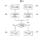
次に、図3に実施の形態1の動き除去手段のアルゴリズムを、図4に透過X線像の分割方法を説明するための図を示し、以下、図3及び図4に基づいて、実施の形態1の動き除去手段の動作を説明する。ただし、以下の説明では、図4に示すように、被写体111に設定した平面の内で、回転装置108の回転中心軸と直交する平面(以下、「ミッドプレーン(mid plane)」と記す)上に設定したX’軸、Y’軸に基づいて、X線発生装置101のX線焦点位置について説明する。また、実施の形態1の透過X線像の撮影は、回転装置108の回転角が1.25度毎に行い、全周分では288枚の撮影を行うものである。
【0029】
まず、透過X線像の内で、図4の(a)に▲1▼で示す範囲の透過X線像である計測前半のデータAを用いて、動き除去手段はミッドプレーンにおける再構成演算を行い、再構成像である断層像I(A)を求める(ステップ301)。
次に、動き除去手段は、再構成像I(A)の内で、予め設定された着目領域(ROI)内での鮮鋭度S(I(A))を算出する(ステップ302)。
【0030】
次に、動き除去手段は、図4の(a)に▲2▼で示す範囲の透過X線像である計測後半のデータBを用いて、ミッドプレーンにおける再構成処理を行い、再構成像I(B)を求める(ステップ303)。
次に、動き除去手段は、再構成像I(B)の着目領域内での鮮鋭度S(I(B))を算出する(ステップ304)。
【0031】
次に、動き除去手段は、鮮鋭度S(I(A))と鮮鋭度S(I(B))を比較する(ステップ305)。
鮮鋭度S(I(A))が鮮鋭度S(I(B))よりも大きい場合には、動き除去手段は、再構成手段に計測前半のデータAを出力する。再構成手段は、計測前半のデータAを用いて3次元再構成演算を行い、生成された三次元X線分布像3DI(A)を画像手段に出力する(ステップ306)。
【0032】
一方、鮮鋭度S(I(B))が鮮鋭度S(I(A))よりも大きい場合には、動き除去手段は、再構成手段に計測後半のデータBを出力する。動き除去手段から計測後半のデータBを受け取った再構成手段は、計測後半のデータB用いて3次元再構成演算を行い、生成された三次元X線分布像3DI(B)を画像手段に出力する(ステップ307)。
【0033】
三次元X線分布像を受け取った画像手段は、三次元X線分布像に対して周知のボリュームレンダリング処理あるいは最大値投影処理等の画像処理を施し三次元X線分布像から三次元的な二次元像である三次元X線像を生成し、表示画面上に三次元X線像を表示する。
【0034】
以上説明したように、実施の形態1の被写体回転型コーンビームX線CT装置では、図4に示すように、動き除去手段は被写体111の周囲から撮影された透過X線像である全計測データを2組に分ける。次に、動き除去手段は2組に分けられた計測データを用いて、ミッドプレーン付近の断層像を再構成する。この後に、動き除去手段は断層像の内で予め設定された領域である注目領域内の鮮鋭度を比較することによって、被写体111の動きのないあるいは動きが少ない側の計測データの組を特定する。動き除去手段は、鮮鋭度の大きい側の再構成手段にデータを出力し、再構成手段が特定された計測データの組を用いて三次元X線分布像を生成する。ここで、画像手段が三次元X線像を生成し、処理表示装置110の表示画面上に表示させるので、計測中の被写体111の動きを含むX線透過像を除去した高画質の三次元X線像を生成することができる。
【0035】
このとき、本実施の形態1では、被写体111の動き含む透過X線像の特定において、ミッドプレーン付近の断層像の生成を1回行うことによってできるので、被写体111の動きの検出に伴う演算負荷を軽減できる。従って、計測の終了から三次元X線像を得るために必要な時間を短縮することができる。その結果、診断効率を向上することができる。
また、得られた三次X線像は、被写体111の動きを含まないので、画質を向上できる。
【0036】
(実施の形態2)
図5は本発明の実施の形態2の被写体回転型コーンビームX線CT装置における動き除去手段のアルゴリズムである。ただし、実施の形態2では、動き除去手段の動作以外は、実施の形態1の被写体回転型コーンビームX線CT装置と同様となるので、以下の説明では、動き除去手段の動作についてのみ説明する。
実施の形態2では、ステップ501〜ステップ505の処理は、実施の形態1の301〜ステップ305の処理と同じとなるので、その説明は省略する。
【0037】
ステップ505において、計測前半のデータAから得た断層像の鮮鋭度S(I(A))の方が大きい場合には、動き検出手段は後半計測データBの前半データ(計測データBの一部)と前半計測データAを合わせた計測データC(図4の(b)に丸3で示す範囲の計測データ)を用いて、再度、ミッドプレーンにおける再構成処理を行い、再構成像I(C)を求める(ステップ506)。
次に、動き除去手段は、再構成像I(C)の着目領域内での鮮鋭度S(I(C))を算出する(ステップ507)。
次に、動き除去手段は、鮮鋭度S(I(A))と鮮鋭度S(I(C))とを比較する(ステップ508)。
鮮鋭度S(I(C))が鮮鋭度S(I(A))よりも大きい場合には、動き除去手段は、再構成手段に計測データCを出力する。再構成手段は、計測データCを用いて3次元再構成演算を行い、生成された三次元X線分布像3DI(C)を画像手段に出力する(ステップ509)。
ステップ508において、鮮鋭度S(I(A))が鮮鋭度S(I(C))よりも大きい場合には、動き除去手段は、再構成手段に計測前半のデータAを出力する。動き除去手段から計測前半のデータAを受け取った再構成手段は、計測前半のデータAを用いて3次元再構成演算を行い、生成された三次元X線分布像3DI(A)を画像手段に出力する(ステップ510)。
【0038】
一方、ステップ505において、計測後半のデータBから得た断層像の鮮鋭度S(I(B))の方が鮮鋭度S(I(A))より大きい場合には、動き検出手段は前半計測データAの後半データと後半計測データBを合わせたデータD(図4の(c)に▲4▼で示す範囲の計測データ)を用いて、再度、ミッドプレーンにおける再構成処理を行い、再構成像I(D)を求める(ステップ511)。
次に、動き除去手段は、再構成像I(D)の着目領域内での鮮鋭度S(I(D))を算出する(ステップ512)。
動き除去手段は、鮮鋭度S(I(B))と鮮鋭度S(I(D))とを比較する(ステップ513)。
鮮鋭度S(I(D))が鮮鋭度S(I(B))よりも大きい場合には、動き除去手段は、再構成手段に計測データDを出力する。再構成手段は、計測データDを用いて3次元再構成演算を行い、生成された三次元X線分布像3DI(D)を画像手段に出力する(ステップ514)。
ステップ513において、鮮鋭度S(I(B))が鮮鋭度S(I(D))よりも大きい場合には、動き除去手段は、再構成手段に計測後半のデータBを出力する。動き除去手段から計測後半のデータBを受け取った再構成手段は、計測後半のデータBを用いて3次元再構成演算を行い、生成された三次元X線分布像3DI(B)を画像手段に出力する(ステップ515)。
【0039】
以上説明したように、実施の形態2の被写体回転型コーンビームX線CT装置では、実施の形態1と同様に、まずステップ505において二分した透過X線像から生成した断層像の鮮鋭度を比較することによって、被写体111の動きのないあるいは動きが少ない側の計測データの組を特定する。すなわち、全透過X線像を二分した計測データの前半側に被写体111の動きが生じたものであるか、計測データの後半側で生じたものであるかを特定する。
【0040】
次に、被写体111の動きが生じた側の計測データをさらに2組に分割し、分割された後半側の計測データと、動きがないあるいは少ない側のデータとを合わせる。ここで、この合わせたデータと動きがないあるいは少ない側のデータとから、再度断層像を再構成し鮮鋭度を比較する。この比較によって、被写体111の動きが最初の1/4回転内に生じたものであるか、最後の1/4回転内に生じたものであるか、あるいは、中間である2/4〜3/4回転内に生じたものであるかを特定し、被写体111の動きがないあるいは少ない側のデータから三次元X線像生成し表示させることによって、被写体111の動きが最初の1/4回転内に生じた場合、あるいは最後の1/4回転内に生じた場合には、三次元X線分布像の生成に使用することができる計測データ数を増大させることができるので、実施の形態1の効果に加えて、実施の形態1よりも三次元分布X線像及び三次元X線像の画質を向上できる。すなわち、再構成に供されるデータ数を増加できるので、画像のS/Nを向上できる。
【0041】
なお、実施の形態1,2では、動き除去手段と再構成手段とを別々に構成する場合について説明したが、これに限定されることはなく、動き除去手段と再構成手段とを一体に構成してもよいことはいうまでもない。動き除去手段と再構成手段とを一体に構成した場合には、ミッドプレーンの断層像を再構成する手段を1つにできるので、前述する効果に加えて、動き除去手段の構成を簡単化できるという効果がある。
【0042】
(実施の形態3)
図6は本発明の実施の形態3の被写体回転型コーンビームX線CT装置における動き除去手段のアルゴリズムである。ただし、実施の形態3では、動き除去手段と再構成手段とが一体に構成されている以外は、実施の形態1の被写体回転型コーンビームX線CT装置と同様となるので、以下の説明では、動き除去手段の動作についてのみ説明する。
【0043】
まず、透過X線像の内で、計測前半のデータAを用いて、動き除去手段は三次元再構成を行い、三次元X線分布像である三次元再構成像3DI(A)を求める(ステップ601)。
動き除去手段は、三次元再構成像3DI(A)の内で、予め設定された着目領域(ROI)内での鮮鋭度S(3DI(A))を算出する(ステップ602)。
【0044】
動き除去手段は、計測後半のデータBを用いて、三次元再構成を行い三次元再構成像3DI(B)を求める(ステップ603)。
この後に、動き除去手段は、三次元再構成像3DI(B)の着目領域内での鮮鋭度S(3DI(B))を算出する(ステップ604)。
【0045】
次に、動き除去手段は、鮮鋭度S(3DI(A))と鮮鋭度S(3DI(B))とを比較する(ステップ605)。
鮮鋭度S(3DI(A))が鮮鋭度S(3DI(B))よりも大きい場合には、動き除去手段は、三次元再構成像3DI(A)を三次元X線分布像として、画像手段に出力する(ステップ606)。
【0046】
一方、鮮鋭度S(3DI(B))が鮮鋭度S(3DI(A))よりも大きい場合には、動き除去手段は、三次元再構成像3DI(B)を三次元X線分布像として、画像手段に出力する(ステップ607)。
【0047】
三次元X線分布像を受け取った画像手段は、三次元X線分布像に対して周知のボリュームレンダリング処理あるいは最大値投影処理等の画像処理を施し三次元X線分布像から三次元的な二次元像すなわち三次元X線像を生成し、表示画面上に三次元X線像を表示する。
【0048】
以上説明したように、実施の形態3の被写体回転型コーンビームX線CT装置では、全透過X線像を2組に分割した後に、各組の透過X線像から三次元X線分布像を生成し、各三次元X線分布像の鮮鋭度を比較することによって、被写体111の動きがないあるいは被写体111の動きが少ない透過X線像の組を特定し、その透過X線像から生成された三次元X線分布像から三次元X線像を生成し表示するので、実施の形態1の効果に加えて、着目領域(ROI)をミッドプレーン以外のスライスに容易に設定できるという効果がある。
【0049】
また、着目領域をミッドプレーン以外のスライスに設定することができるので、たとえば、着目領域をtransaxial像(図1中のXY平面の像)、coronal像(図1中のXZ平面の像)、あるいは、sagittal像(図1中のYZ平面の像)の何れにも設定できる。
さらには、着目領域を、三次元的に設定することもできるという効果がある。このように、本実施の形態3では、種々の形式で着目領域を容易に設定できるので、作業効率すなわち診断効率をさらに向上できるという効果もある。
【0050】
(実施の形態4)
図7は本発明の実施の形態4の被写体回転型コーンビームX線CT装置における動き除去手段のアルゴリズムである。ただし、実施の形態4では、動き除去手段と再構成手段とが一体に構成されている以外は、実施の形態3の被写体回転型コーンビームX線CT装置と同様となるので、以下の説明では、動き除去手段の動作についてのみ説明する。
実施の形態4では、ステップ701〜ステップ705の処理は、実施の形態3の601〜ステップ605の処理と同じとなるので、その説明は省略する。
【0051】
ステップ705において、計測前半のデータAから三次元再構成像の鮮鋭度S(3DI(A))の方が大きい場合には、動き検出手段は計測後半のデータBの前半データ(計測データBの一部)と計測前半のデータAを合わせた計測データC(図4の(b)に丸3で示す範囲の計測データ)を用いて、再度、三次元再構成を行い三次元再構成像3DI(C)を求める(ステップ706)。
次に、動き除去手段は、三次元再構成像3DI(C)の着目領域内での鮮鋭度S(3DI(C))を算出する(ステップ707)。
【0052】
次に、動き除去手段は、鮮鋭度S(3DI(A))と鮮鋭度S(3DI(C))とを比較する(ステップ708)。
鮮鋭度S(3DI(C))が鮮鋭度S(3DI(A))よりも大きい場合には、動き除去手段は、三次元X線分布像である三次元再構成像3DI(C)を画像手段に出力する(ステップ709)。
ステップ708において、鮮鋭度S(3DI(A))が鮮鋭度S(3DI(C))よりも大きい場合には、動き除去手段は、三次元X線分布像3DI(A)を画像手段に出力する(ステップ710)。
【0053】
一方、ステップ705において、計測後半のデータBから得た断層像の鮮鋭度S(3DI(B))の方が鮮鋭度S(3DI(A))より大きい場合には、動き検出手段は計測前半のデータAの後半データと計測後半のデータBを合わせたデータD(図4の(c)に▲4▼で示す範囲の計測データ)を用いて、再度、三次元再構成を行い、三次元再構成像3DI(D)を求める(ステップ711)。
次に、動き除去手段は、三次元再構成像3DI(D)の着目領域内での鮮鋭度S(3DI(D))を算出する(ステップ712)。
【0054】
次に、動き除去手段は、鮮鋭度S(3DI(B))と鮮鋭度S(3DI(D))とを比較する(ステップ713)。
鮮鋭度S(3DI(D))が鮮鋭度S(3DI(B))よりも大きい場合には、動き除去手段は、三次元X線分布像である三次元再構成像3DI(D)を画像手段に出力する(ステップ714)。
ステップ713において、鮮鋭度S(3DI(B))が鮮鋭度S(3DI(D))よりも大きい場合には、動き除去手段は、三次元X線分布像である三次元再構成像3DI(B)を画像手段に出力する(ステップ715)。
【0055】
以上説明したように、実施の形態4の被写体回転型コーンビームX線CT装置では、実施の形態3と同様に、まずステップ705において2組に分けた透過X線像の組から被写体111の動きのないあるいは動きが少ない側の三次元X線分布像を特定する。すなわち、全透過X線像を二分した計測データの前半側に被写体111の動きが生じたものであるか、計測データの後半側で生じたものであるかを特定する。
【0056】
次に、被写体111の動きが生じた側の計測データをさらに2組に分割し、分割された計測データの内で動きがないあるいは少ない側のデータに連続する計測データと、動きがないあるいは少ないと判定された側の計測データとを合わせる。ここで、この合わせた計測データと動きがないあるいは少ない側のデータとからそれぞれ三次元再構成された三次元X線分布像の鮮鋭度を比較する。この比較によって、被写体111の動きが最初の1/4回転内に生じたものであるか、最後の1/4回転内に生じたものであるか、あるいは、中間である2/4〜3/4回転内に生じたものであるかを特定し、被写体111の動きがないあるいは少ない側のデータから生成された三次元X線分像に基づいて、三次元X線像を生成し表示させる。これによって、被写体111の動きが最初の1/4回転内に生じた場合、あるいは最後の1/4回転内に生じていた場合には、三次元X線分布像の生成に使用することができる計測データ数を増大させることができるので、実施の形態1,3の効果に加えて、実施の形態3よりも三次元分布X線像及び三次元X線像の画質を向上できる。
【0057】
(実施の形態5)
図8は本発明の実施の形態5の被写体回転型コーンビームX線CT装置における動き除去手段のアルゴリズムである。ただし、実施の形態5では、動き除去手段の動作以外は、実施の形態3,4の被写体回転型コーンビームX線CT装置と同様となるので、以下の説明では、動き除去手段の動作についてのみ説明する。
【0058】
まず、透過X線像の内で、計測前半のデータAを用いて、動き除去手段は三次元再構成を行い、三次元X線分布像である三次元再構成像3DI(A)を求め(ステップ801)、得られた三次元再構成像を一時的に半導体メモリ等からなる図示しない周知の格納手段に格納する(ステップ802)。
【0059】
次に、動き除去手段は、計測後半のデータBを用いて、三次元再構成を行い三次元再構成像3DI(B)を求め(ステップ803)、得られた三次元再構成像を一時的に格納手段に格納する(ステップ804)。
【0060】
次に、動き除去手段は、格納手段に格納される三次元再構成像3DI(A),3DI(B)を読み出し、三次元再構成像3DI(A)と三次元再構成像3DI(B)とを加算平均し、三次元再構成像3DI(A+B)を求める(ステップ805)。
次に、動き除去手段は、三次元再構成像3DI(A),3DI(B),3DI(A+B)の鮮鋭度S(3DI(A)),S(3DI(B)),S(3DI(A+B))を求め、それぞれの鮮鋭度を比較する(ステップ806)。
【0061】
鮮鋭度S(3DI(A))が鮮鋭度S(3DI(B)),S(3DI(A+B))よりも大きい場合には、動き除去手段は、三次元再構成像3DI(A)を三次元X線分布像として、画像手段に出力する(ステップ807)。
鮮鋭度S(3DI(A+B))が鮮鋭度S(3DI(A)),S(3DI(B))よりも大きい場合には、動き除去手段は、三次元再構成像3DI(A+B)を三次元X線分布像として、画像手段に出力する(ステップ808)。
さらには、鮮鋭度S(3DI(B))が鮮鋭度S(3DI(A)),S(3DI(A+B))よりも大きい場合には、動き除去手段は、三次元再構成像3DI(B)を三次元X線分布像として、画像手段に出力する(ステップ809)。
【0062】
以上説明したように、実施の形態5の被写体回転型コーンビームX線CT装置では、被写体111の全周方向から撮影した透過X線像を2つの組に分割し、それぞれの組毎に三次元X線分布像を生成すると共に、各組の三次元X線分布像の加算平均し、それぞれの鮮鋭度を計算し比較することによって、最も鮮鋭度が大きい三次元X線分布像を特定し、特定された三次元X線分布像から三次元X線像を生成することによって、比較的演算負荷が大きい三次元X線分布像を生成するための再構成演算回数を2回で済ますことができるので、透過X線像の計測終了すなわち画像生成開始から実際の三次元X線像の生成までの時間を短縮することができる。
【0063】
(実施の形態6)
図9は本発明の実施の形態6の被写体回転型コーンビームX線CT装置における動き除去手段のアルゴリズムである。ただし、実施の形態6では、動き除去手段の動作以外は、実施の形態1の被写体回転型コーンビームX線CT装置と同様となるので、以下の説明では、動き除去手段の動作についてのみ説明する。なお、図9は実施の形態2の動き除去手段に、データ領域の拡大と再構成とを繰り返す機能を付加した構成となっており、実施の形態4の被写体回転型コーンビームX線CT装置にも適用可能である。
実施の形態6では、ステップ901〜ステップ905の処理は、実施の形態1の301〜ステップ305の処理と同じとなるので、その説明は省略する。
【0064】
ステップ905において、計測前半のデータAから得た断層像の鮮鋭度S(I(A))の方が大きい場合には、動き除去手段は前半計測データAに所定数の計測データE1を加算する(ステップ906)。ただし、このときの所定数の計測データは、後半計測データBの内で、予め設定された数の計測データである。
動き除去手段は、前半計測データAに所定数の計測データE1を加算したデータA+E1を用いて、再度、ミッドプレーンにおける再構成処理を行い、再構成像I(A+E1)を求める(ステップ907)。
次に、動き除去手段は、再構成像I(A+E1)の着目領域内での鮮鋭度S(I(A+E1))を算出する(ステップ908)。
【0065】
次に、動き除去手段は、鮮鋭度S(I(A))と鮮鋭度S(I(A+E1))とを比較し、鮮鋭度の増加率を調べる。その結果、鮮鋭度の増加率が予め設定された鮮鋭度の増加率である10よりも小さい場合には、動き除去手段は、再構成手段に計測データCを出力する。ここで計測データCとは、計測データAに計測データBの一部(図4の(b)参照)のデータである所定数の計測データE 1 を加えたものである。再構成手段は、計測データCを用いて3次元再構成演算を行い、生成された三次元X線分布像3DI(C)を画像手段に出力する(ステップ909)。
【0066】
一方、ステップ909において、鮮鋭度S(I(A))とS(I(A+E 1 ))を比較して求めた鮮鋭度の増加率が予め設定された鮮鋭度の増加率である10よりも大きい場合には、データA+E1に所定数の計測データE2を加算し(ステップ910)、再度、ステップ907に進み鮮鋭度の増加率を調べる。
ステップ907において、データA+E 1 +E 2 を用いてミッドプレーン再構成処理を行い、再構成像I(A+E 1 +E 2 )求める。ステップ908において、再構成像I(A+E 1 +E 2 )の着目領域内での鮮鋭度S(I(A+E 1 +E 2 ))を算出する。ステップ909において、鮮鋭度S(I(A+E 1 ))と鮮鋭度S(I(A+E 1 +E 2 ))を比較し、鮮鋭度の増加率が予め設定された鮮鋭度の増加率である10よりも小さい場合には、再構成手段にステップ910で求められた計測データCを出力する。このとき、計測データCは、計測データAに計測データBの一部のデータである所定数の計測データE 1 +E 2 を加えたデータA+E 1 +E 2 である。再構成手段は、計測データCを用いて3次元再構成演算を行う。
一方、ステップ909において、鮮鋭度S(I(A+E 1 ))と鮮鋭度S(I(A+E 1 +E 2 ))を比較し、鮮鋭度の増加率が予め設定された鮮鋭度の増加率である10よりも大きい場合には、データA+E 1 +E 2 に、所定数の計測データE 3 を加算し(ステップ910)、再度、ステップ907に進み鮮鋭度の増加率を調べる。
鮮鋭度の増加率が予め設定された鮮鋭度の増加率よりも小さくなるまで、ステップ907からステップ910までのミッドプレーン付近の再構成、再構成像のROI内鮮鋭度の算出、鮮鋭度の増加率の判定、及び、所定数の計測データE 1 、E 2 …の加算を繰り返す。
【0067】
一方、前述するステップ905において、計測後半のデータBから得た断層像の鮮鋭度S(I(B))の方が大きい場合には、動き検出手段は計測後半データBに所定数の計測データF1を加算する(ステップ912)。以降、前述のステップ907〜ステップ910と同様の処理を行う。すなわち、鮮鋭度の増加率が予め設定された鮮鋭度の増加率よりも小さくなるまで、ステップ913〜ステップ916までのミッドプレーン付近の再構成、再構成像のROI内鮮鋭度の算出、鮮鋭度の増加率の判定、及び、所定数の計測データF1,F2…の加算を繰り返す。
【0068】
以上説明したように、実施の形態6の被写体回転型コーンビームX線CT装置では、データ領域を拡大、拡大されたデータ領域の再構成を行い、鮮鋭度を算出する。算出された鮮鋭度を、拡大前のデータ領域での再構成像に対して算出した鮮鋭度と比較する。鮮鋭度の増加率が所定の値より大きい場合には、再度、データ領域を拡大し鮮鋭度の算出を行う。以上のデータ領域を拡大した再構成像とその再構成像からこれらの処理を繰り返し、鮮鋭度の増加率が所定の値より小さくなったところで、データ領域の拡大を終了するので、より良い画質を追求することができる。
【0069】
なお、以上の説明では、実施の形態2の被写体回転型コーンビームX線CT装置における鮮鋭度の増加率を10%としたが、これに限定されることはない。鮮鋭度の増加率の設定は、予め設定しておいてもよいが、術者が任意に設定できるように操作卓に設定スイッチを設けることによって、術者の好みに応じた3D再構成像を得ることができる。
【0070】
また、実施の形態2,4,6の被写体回転型コーンビームX線CT装置では、データ領域の拡大を行う。ここで、データ領域の拡大法は様々に考えられる。実施の形態では、鮮鋭度の高いデータ領域に、鮮鋭度の低いデータ領域のうち鮮鋭度の高いデータ領域に近い領域を半分だけ加えている。加える量は半分に限らず、被写体が動いた可能性に合わせて変化させることも考えられる。
さらには、実施の形態1,2と同様に、動き除去手段と再構成手段とを一体に構成してもよいことはいうまでもない。
【0071】
(実施の形態7)
図10は本発明の実施の形態7の被写体回転型コーンビームX線CT装置の概略構成を説明するための図である。実施の形態7では、全透過X線像の内で、重複した投影角で撮影された透過X線像に基づいて、撮影中での被写体111の動き(移動)を検出する動き検出手段以外は、実施の形態1〜6の被写体回転型コーンビームX線CT装置と同様となるので、以下の説明では、動き検出手段の動作についてのみ説明する。
【0072】
まず、動き検出手段は、所定の位置Aで計測された画像Aと位置Bで計測された画像Bの間で比較を行い、被写体の動きを検出する(ステップ1001)。次に、動き検出手段は、動きの有無を判定する(ステップ1002)。ただし、動きの検出および判定の詳細については後述する。
ステップ1002において、動き検出手段が被写体の動きがないと判定した場合には、3次元再構成処理に入る(ステップ1003)。一方、動きがあると判定した場合には、前述した実施の形態1〜6に示す補正処理に入る(ステップ1004)。
【0073】
このように、実施の形態7の被写体回転型コーンビームX線CT装置では、計測画像において動き検出手段が動きを検出した場合のみ、動きを除去するための補正処理に入るので、動きがない場合の演算量が少なくて済む。その結果、診断効率をさらに向上させることができる。
【0074】
次に、動き検出手段における動きの検出方法について説明する。
画像計測開始角度Aと画像計測終了角度Bを一致させる、あるいは、開始角度Aよりも終了角度Bを大きくすることにより、ある角度で重複して画像を計測する。ここで、角度Aで計測された画像を計測画像Aとし、角度Bで計測された画像を計測画像Bとする。
【0075】
(第1の方法)
図11は、動き検出の第1の方法を説明するための図である。ただし、第1の方法は、所定の角度で重複して計測された画像がある場合に適用可能である。
まず、関心領域(ROI)の設定を行う(ステップ1101)。この後、関心領域(ROI)において、重複して計測された画像(重複計測画像)Aと画像Bとを特定する(ステップ1102,1103)。この重複計測画像A,Bの間で、差分画像Cを生成する(ステップ1104)。ただし、差分画像Cの生成法は、重複計測画像Aの画素値から重複計測画像Bの対応する位置の画素値を減算することによって計算される。
次に、差分画像Cにおいて、値の範囲を求める(ステップ1105)。ただし、「値の範囲」は、差分画像C中の最大値と最小値との差で定義する。
値の範囲が所定の値より大きいか否かを判定し(ステップ1106)、値の範囲の方が所定の値よりも大きい場合には、被写体111に動きがあったと判定する(ステップ1107)。一方、ステップ1106において、値の範囲の方が所定の値よりも小さい場合には、被写体111に動きがなかったと判定する(ステップ1108)。ただし、所定の値とは、例えば、差分前の画像の最大画素値の2%とする。
以上説明したように、動き検出の第1の方法では、画素値の差分演算すなわち減算という簡単な演算で動き検出が可能であるという特長をもつ。その結果、被写体111の動きの検出に要する時間を短縮することができるので、診断効率をさらに向上できる。
この第1の方法は、重複計測画像Aと重複計測画像Bの計測条件が等しく、かつ、画像検出装置の応答が早い場合に好適である。具体的には、図1に示した装置では、計測条件とは、テレビカメラに入射する光量を調節するために光学系の内部にある光学絞りの開口面積やX線量などを示し、画像検出装置の応答とは、テレビカメラの蓄積電荷の読み出し特性の立上りを示す。
【0076】
(第2の方法)
図12は動き検出の第2の方法を説明するための図である。ただし、第2の方法は、前述した第1の方法と同様に、所定の角度で重複して計測された画像がある場合に適用可能である。
図12から明らかなように、動き検出の第2の方法は、ステップ1203及びステップ1205における、重複計測画像A,Bの対数変換のみが異なり、他は第1の方法と同じとなる。
すなわち、ステップ1202とステップ1204とで特定された重複計測画像A,Bとをそれぞれ対数変換し、重複計測画像Aの対数画像A*と重複計測画像Bの対数画像B*とを得る。対数画像A*と対数画像B*との間で差分をとり、対数差分画像C*を生成する。次に、対数差分画像C*の範囲を算出し、範囲が所定の値より大きい場合には、動きがあったと判定するので、第1の方法と同様に、簡単な演算で動き検出が可能であるという特長をもつ。
さらには、第2の方法は、重複計測画像Aと重複計測画像Bとの計測時に、光学絞りおよび線量が変化した場合でも、信頼性の高い動き検出が可能であるという特長をもつ。または、テレビカメラの立ち上がり遅い場合でも、信頼性の高い動き検出が可能であるという特長をもつ。
【0077】
(第3の方法)
図13は動き検出の第3の方法を説明するための図である。ただし、第3の方法は、重複して計測された画像がない場合にも適用可能である。また、以下の説明では、所定の枚数の計測画像が3枚の場合について説明する。よって、第3の方法では、計測画像をA,B,C,…,D,E,Fとする。
まず、関心領域(ROI)の設定を行う(ステップ1301)。この後、関心領域(ROI)において、回転撮影開始直後と終了直前との所定枚数の画像すなわち計測画像A,B,C,D,E,Fを特定する(ステップ1302)。
次に、連続する2枚の画像間の差分画像を生成する(ステップ1303)。すなわち、計測画像Bと計測画像Aとの差分画像、計測画像Cと計測画像Bとの差分画像、計測画像Eと計測画像Dとの差分画像、計測画像Fと計測画像Dとの差分画像、及び計測画像Aと計測画像Fとの差分画像Nをそれぞれ求める。
次に、それぞれの差分画像での値の範囲を算出する(ステップ1304)。ただし、第3の方法における「値の範囲」は、前述した第1,2の方法での「値の範囲」と同様に、差分画像中の最大値と最小値との差で定義する。
次に、回転撮影開始直後の計測画像Aと終了直前の計測画像Fとの差分画像の値の範囲Nが、その他の差分画像の値の範囲に比較して最大であるかを判定する(ステップ1305)。
ステップ1305において、差分画像の値の範囲Nが、その他の差分画像の値の範囲に比較して最大の場合には、撮影中に被写体の動きがあったものと判定する(ステップ1306)。それ以外の場合には、撮影中の被写体の動きはなかったものとして判定する(ステップ1307)。
以上説明したように、第3の方法では、隣接する角度の計測画像の相違を比較することにより、重複投影がなくても簡単な演算で動き検出が可能であるという特長がある。
また、第3の方法は、光学絞りおよび線量が一定であり、かつ、テレビカメラの立上りが早い場合に好適である。
【0078】
(第4の方法)
図14は動き検出の第4の方法を説明するための図である。ただし、第4の方法は、前述した第3の方法と同様に、重複して計測された画像がない場合にも適用可能である。
図14から明らかなように、動き検出の第4の方法は、ステップ1403における計測画像A,B,C,D,E,Fの対数変換のみが異なり、他は第3の方法と同じとなる。
すなわち、ステップ1403で回転撮影開始直後と終了直前との所定枚数の計測画像A,B,C,D,E,Fに対して、それぞれ対数変換を行い対数画像を得る。次に、得られた対数画像の内で連続する2枚の画像間の差分画像を生成し(ステップ1404)、それぞれの差分画像での値の範囲を算出する(ステップ1405)。この後、計測画像Aの対数画像と計測画像Fの対数画像との差分画像の値の範囲Nが、その他の対数画像の差分画像の値の範囲に比較して最大であるかを判定することによって(ステップ1406)、撮影中における被写体の動きを検出するので、第3の方法と同様に、重複投影がなくても簡単な演算で動き検出が可能であるという特長がある。
また、第4の方法は、光学絞りおよび線量が変化する場合でも、信頼性の高い動き検出が可能であるという特長をもつ。
さらには、テレビカメラの立ち上がり遅い場合でも、信頼性の高い動き検出が可能であるという特長をもつ。
【0079】
前述した第1〜4の方法において、動きの検出を容易にするために、被写体にマーカーを取り付けることも考えられる。マーカーには、X線吸収率の高い物質を用いる。具体的にはマーカーは、タングステン製やステンレス製の円盤、球、板、棒などである。
【0080】
なお、本実施の形態では、被写体の透過X線像として被写体の1回転分の投影データから被写体の三次元X線分布像を再構成することとしたが、これに限定されることはなく、1回転分以上の透過X線像を撮影した場合には、その透過データを2以上の組に分割することによって本願発明を適用できることはいうまでもない。
【0081】
また、本実施の形態では、撮像手段としてX線I.I.103、光学系104及びテレビカメラ106からなる二次元透過X線像検出装置を用いる場合について説明したが、これに限定されることはなく、たとえば、蛍光板と2次元フォトダイオードアレイとから構成される検出器、蛍光板とテレビカメラとから構成される検出器、あるいは、2次元薄膜トランジスタ(TFTあるいはCMOS)配列から構成される半導体検出器等を用いてもよいことはいうまでもない。
【0082】
また、二次元透過X線像検出装置102の素子配列は二次元配列としたが、これに限定されることはなく、たとえば、1次元配列の検出器でもよいことはいうまでもない。
また、本実施の形態では、被写体111の設置状態は立位であるが、座位、あるいは保持装置ごと傾斜させた状態等の何れの設置状態でもよいことはいうまでもない。
【0083】
また、本実施の形態では、床面上に対向配置されたX線発生装置101と二次元透過X線像検出装置102との間に被写体111を回転可能に設置する構成としたが、これに限定されることはなく、たとえば、対向配置されたX線発生装置101と二次元透過X線像検出装置102とからなる撮影系を回転可能な回転板に固定し、回転板を回転させることによって床面に対して固定された被写体111の周囲に撮影系を回転させ被写体111の周囲から透過X線像を撮影する構成としてもよいことはいうまでもない。さらには、被写体111を回転させると共に撮影系を回転させる構成としてもよいことはいうまでもない。
【0084】
また、本実施の形態では、被写体111を回転装置108で回転させるのみとしたが、これに限定されることはなく、たとえば、回転装置108に移動機構を設けることにより回転装置108の回転に伴って移動機構を移動させ、被写体111に設定した計測対象部位を二次元透過X線像検出装置102の計測可能視野内に入れる構成としてもよいことはいうまでもない。
【0085】
また、本実施の形態では、最初に行う再構成処理のデータ領域を計測前半データと計測後半データの2つとしたが、このデータ領域の取り方は様々に考えられる。例えば、第1のデータ領域を全体の3/4のデータとし、残りのデータを第2のデータ領域とすることできる。また例えば、計測データを4分割し、4つのデータ領域に対して処理を開始することもできる。
【0086】
さらには、本発明は、人体等の生物一般のX線画像を撮影する医療用のコーンビームCT装置、及び、航空荷物等のX線画像を撮影するX線荷物検査装置の何れにも適用可能なことはいうまでもない。X線荷物検査装置に本発明を適用して、撮影中の荷物を容易に検出し除去することができるので、内容物の移動に伴うアーチファクトの発生を防止でき、航空荷物等のX線画像の画質を向上できる。
【0087】
以上、本発明者によってなされた発明を、前記発明の実施の形態に基づき具体的に説明したが、本発明は、前記発明の実施の形態に限定されるものではなく、その要旨を逸脱しない範囲において種々変更可能であることは勿論である。
【0088】
【発明の効果】
本願において開示される発明のうち代表的なものによって得られる効果を簡単に説明すれば、下記の通りである。
(1)撮影中における被写体の動きを検出し、容易に除去することができる。
(2)被写体の周囲から撮影したX線透過像から生成した三次元X線像の画質を向上できる。
【図面の簡単な説明】
【図1】本発明の実施の形態1のコーンビームCT装置である被写体回転型コーンビームX線CT装置の概略構成を説明するための図である。
【図2】実施の形態1の被写体回転型コーンビームX線CT装置における計測動作を説明するためのフローである。
【図3】実施の形態1の動き除去手段のアルゴリズムを説明するための図である。
【図4】実施の形態1の動き除去手段中の分割手段における透過X線像の分割方法を説明するための図である。
【図5】本発明の実施の形態2の被写体回転型コーンビームX線CT装置における動き除去手段のアルゴリズムである。
【図6】本発明の実施の形態3の被写体回転型コーンビームX線CT装置における動き除去手段のアルゴリズムである。
【図7】本発明の実施の形態4の被写体回転型コーンビームX線CT装置における動き除去手段のアルゴリズムである。
【図8】本発明の実施の形態5の被写体回転型コーンビームX線CT装置における動き除去手段のアルゴリズムである。
【図9】本発明の実施の形態6の被写体回転型コーンビームX線CT装置における動き除去手段のアルゴリズムである。
【図10】本発明の実施の形態7の被写体回転型コーンビームX線CT装置の概略構成を説明するための図である。
【図11】本発明の実施の形態7の被写体回転型コーンビームX線CT装置の動き検出の第1の方法を説明するための図である。
【図12】本発明の実施の形態7の被写体回転型コーンビームX線CT装置の動き検出の第2の方法を説明するための図である。
【図13】本発明の実施の形態7の被写体回転型コーンビームX線CT装置の動き検出の第3の方法を説明するための図である。
【図14】本発明の実施の形態7の被写体回転型コーンビームX線CT装置の動き検出の第4の方法を説明するための図である。
【符号の説明】
101…X線発生装置、102…二次元透過X線像検出装置、103…X線イメージインテンシファイア、104…光学系、105…光学絞り、106…テレビカメラ、107…保持装置、108…回転装置、109…制御収集装置、110…処理表示装置、111…被写体。[0001]
BACKGROUND OF THE INVENTION
The present invention relates to a cone beam CT apparatus, and more particularly to a technique effective when applied to obtaining a high-resolution three-dimensional X-ray image using a two-dimensional X-ray image detection apparatus.
[0002]
[Prior art]
Conventionally, there has been an X-ray CT apparatus that creates a tomographic image by measuring the distribution of the X-ray absorption coefficient inside an object using X-rays. In this X-ray CT apparatus, a transmission X-ray image (projection data) of a subject is photographed (measured) while rotating an X-ray source and a one-dimensional X-ray detector arranged opposite to each other around the subject. The tomogram was obtained by reconstructing the projection data. As a method of obtaining a three-dimensional X-ray image using a conventional X-ray CT apparatus, there is a method of stacking a large number of tomographic images. However, in the method of stacking a large number of tomographic images, in order to make the resolution in the direction perpendicular to the rotation plane equal to the resolution in the rotation plane, it is necessary to measure multiple exposures for a very long time.
[0003]
In order to shorten the measurement time and reduce exposure, a spiral scan method has been developed in which the X-ray source and detector are rotated many times while moving the subject in a direction perpendicular to the rotation plane of the detector. However, in the X-ray CT apparatus using the spiral scan method, there is a problem that the resolution in the direction perpendicular to the rotation plane is lower than the resolution in the rotation plane as the measurement time is shortened.
[0004]
In order to shorten the measurement time and increase the resolution in the direction perpendicular to the rotation surface, a cone beam X-ray CT apparatus using a two-dimensional X-ray detector has been developed. The cone beam X-ray CT apparatus performs measurement while rotating an imaging system in which an X-ray source for irradiating X-rays radially and a two-dimensional detector are opposed to each other around the entire circumference of a subject. The cone beam X-ray CT apparatus reconstructs a three-dimensional X-ray distribution image from the obtained projection data, and performs image processing such as volume rendering processing or maximum value projection processing on the three-dimensional X-ray distribution image. Thus, the three-dimensional X-ray distribution image is converted into a three-dimensional X-ray image that is a three-dimensional two-dimensional image and then displayed on the display device.
[0005]
Since the conventional cone beam X-ray CT apparatus is configured to use a two-dimensional detector as a detector, data necessary for reconstructing a three-dimensional X-ray distribution image can be obtained by measurement for one rotation. It was. Further, the conventional cone beam X-ray CT apparatus can obtain a three-dimensional X-ray image having the same voxel resolution as that in the rotation plane in a direction perpendicular to the rotation plane by using a two-dimensional detector as a detector. did it.
[0006]
In contrast to a cone beam X-ray CT apparatus that rotates an imaging system around a subject, there is a subject rotation type cone beam X-ray CT apparatus that rotates a subject as a cone beam X-ray CT apparatus that simplifies the system. . An object rotation type cone beam X-ray CT apparatus is described in, for example, “Proceedings of the 54th Annual Meeting of the Japanese Society of Radiological Technology, p. 180” (hereinafter referred to as “
[0007]
Since the object rotation type cone beam X-ray CT apparatus does not require a large gantry for rotating the X-ray source and the X-ray detector together, the positions of the X-ray source and the X-ray detector can be freely set. It was possible to set and change the magnification during measurement. In addition, since the subject rotation type cone beam X-ray CT apparatus can freely set the positional relationship between the X-ray detector and the subject, when the field of view of the detector is limited, the region to be measured in the subject Could easily be put into view.
[0008]
[Problems to be solved by the invention]
As a result of examining the prior art, the present inventor has found the following problems.
In the conventional subject rotation type cone beam X-ray CT apparatus, the subject is fixed to the subject holding base and the rotation of the turntable is set to be a smooth rotational motion so that the subject does not move during the measurement. However, there is a problem that the subject easily moves during measurement due to the rotational movement.
[0009]
In the case where a conventional subject rotation type cone beam X-ray CT apparatus is used for medical purposes, it has been desired to shorten the restraint time of a subject as a subject as much as possible. In other words, in medical applications, the subject as a subject is generally ill. For this reason, it has been difficult for the subject to maintain the same posture for a long time.
[0010]
As a method for shortening the holding period of the same posture of the subject, that is, the time required for measurement, it is conceivable to increase the rotational speed of the subject. However, the time required for one rotation of the subject is 3 to 4 seconds or more, and when the subject is rotated at a higher speed than this, the subject turns into a so-called eye that feels abnormal rotation. There was a problem that. In addition, when the subject is rotated at a high speed, the centrifugal force applied to the subject also increases with an increase in the rotational speed, which causes a problem that the subject moves during measurement. If the subject moves during the measurement, there is a problem that “blur” or “blur” occurs in the three-dimensional X-ray distribution image generated by the reconstruction, and the image quality of the three-dimensional X-ray image is deteriorated. there were.
[0011]
An object of the present invention is to provide a cone beam CT apparatus capable of detecting and removing the movement of a subject during photographing.
Another object of the present invention is to provide a cone beam CT apparatus capable of improving the image quality of a three-dimensional X-ray image generated from an X-ray transmission image taken from around the subject.
The above and other objects and novel features of the present invention will be apparent from the description of this specification and the accompanying drawings.
[0012]
[Means for Solving the Problems]
Of the inventions disclosed in this application, the outline of typical ones will be briefly described as follows.
In the cone beam CT apparatus for generating and displaying an X-ray tomographic image and / or a three-dimensional X-ray image of the subject based on a transmitted X-ray image of the subject photographed by irradiating X-rays from around the subject, the transmission The X-ray image is divided into a plurality of different sets, and the sharpness for each X-ray distribution image obtained by reconstructing the transmitted X-ray image for each set is calculated, and the transmission X of the set with the highest sharpness is calculated. Based on the line image, an X-ray tomographic image and / or a three-dimensional X-ray image of the subject is generated and displayed.
[0013]
According to the above-described means, first, the transmitted X-ray images are divided into a plurality of different sets, and the X-ray distribution image obtained by reconstructing the transmitted X-ray images for each set, that is, the sharpness for each CT image is determined. calculate. Next, by comparing the sharpness of each X-ray distribution image, the motion of the subject being imaged that causes blurring in the X-ray tomographic image or three-dimensional X-ray image that is the display image is detected.
[0014]
That is, when a motion occurs in the subject being imaged, blurring occurs in the X-ray tomogram or / and the three-dimensional X-ray image obtained by reconstruction. As a result, it is known that the contrast is lowered in a part of the transmitted X-ray image, particularly in a portion having a small absorption coefficient. Accordingly, in the present invention, by comparing the sharpness of each transmitted X-ray image divided into a plurality of sets, the transmitted X-ray image that does not include the transmitted X-ray image in which the subject moves relative to the reference coordinates at the time of reconstruction, that is, reconstruction. A set of X-ray images can be identified.
[0015]
Next, by generating and displaying an X-ray tomographic image and / or a three-dimensional X-ray image of the subject from the set of transmission X-ray images having the highest sharpness specified, the subject of the subject being photographed causing the blur is displayed. Since an X-ray distribution image including motion can be removed, the image quality of an X-ray tomographic image and / or a three-dimensional X-ray image that is a display image can be improved.
[0016]
DETAILED DESCRIPTION OF THE INVENTION
Hereinafter, the present invention will be described in detail with reference to the drawings together with embodiments (examples) of the invention.
Note that components having the same function are denoted by the same reference symbols throughout the drawings for describing the embodiment of the invention, and the repetitive description thereof is omitted.
[0017]
(Embodiment 1)
FIG. 1 is a diagram for explaining a schematic configuration of a subject rotation type cone beam X-ray CT apparatus which is a cone beam CT apparatus according to
The subject rotation type cone beam X-ray CT apparatus according to the first embodiment includes an X-ray generation apparatus (X-ray source) 101, a two-dimensional transmission X-ray image detection apparatus (imaging means) 102, a holding apparatus (support means) 107, and a rotation. An apparatus (rotating means) 108, a
Further, in the specification of the present application, a pixel value of a transmitted X-ray image, a CT value of a three-dimensional X-ray segment image, or an image of a display image (X-ray tomographic image, three-dimensional X-ray image, or two-dimensional X-ray image). A value indicating contrast such as a level value is referred to as “sharpness”.
[0018]
The
The
[0019]
The two-dimensional transmission X-ray
[0020]
The holding
The
[0021]
The
[0022]
In the subject rotation type cone beam X-ray CT apparatus of the first embodiment, for example, the X-ray I.D. I. The distance to the
[0023]
FIG. 2 is a flowchart for explaining the measurement operation in the subject rotation type cone beam X-ray CT apparatus of the first embodiment. The measurement operation of the subject rotation type cone beam X-ray CT apparatus according to the first embodiment will be described below with reference to FIG. However, in the following description, a procedure for collecting a transmission X-ray image for one rotation of the imaging system as a transmission X-ray image for the entire circumference of the subject 111 will be described.
[0024]
First, the observer fixes the subject 111 to the holding device 107 (step 201).
Next, when an observer gives an instruction to start measurement from a console (not shown), measurement of a transmitted X-ray image (projection data) is started according to a control signal from the
[0025]
When the
Along with the X-ray irradiation from the
The
The X-ray irradiation, image acquisition, and image collection in
[0026]
When the transmission X-ray image for the entire circumference has been captured (collected), the
Thereafter, the
In the
[0027]
Next, in the
However, in the above description, the rotation of the
[0028]
Next, FIG. 3 shows an algorithm of the motion removal means of the first embodiment, and FIG. 4 shows a diagram for explaining a transmission X-ray image segmentation method. Hereinafter, based on FIG. 3 and FIG. The operation of the motion removal means of
[0029]
First, using the data A in the first half of the measurement, which is the transmission X-ray image in the range indicated by (1) in FIG. Then, a tomographic image I (A) which is a reconstructed image is obtained (step 301).
Next, the motion removal means calculates a sharpness S (I (A)) within a preset region of interest (ROI) in the reconstructed image I (A) (step 302).
[0030]
Next, the motion removal means performs reconstruction processing in the midplane using the data B in the latter half of the measurement, which is a transmission X-ray image in the range indicated by (2) in FIG. (B) is obtained (step 303).
Next, the motion removal means calculates the sharpness S (I (B)) in the region of interest of the reconstructed image I (B) (step 304).
[0031]
Next, the motion removal means compares the sharpness S (I (A)) with the sharpness S (I (B)) (step 305).
When the sharpness S (I (A)) is greater than the sharpness S (I (B)), the motion removal unit outputs the first half of data A to the reconstruction unit. The reconstruction unit performs a three-dimensional reconstruction operation using the data A in the first half of the measurement, and outputs the generated three-dimensional X-ray distribution image 3DI (A) to the image unit (step 306).
[0032]
On the other hand, when the sharpness S (I (B)) is larger than the sharpness S (I (A)), the motion removal unit outputs the data B in the latter half of the measurement to the reconstruction unit. The reconstruction means that has received the data B in the latter half of the measurement from the motion removal means performs a three-dimensional reconstruction operation using the data B in the latter half of the measurement, and outputs the generated three-dimensional X-ray distribution image 3DI (B) to the image means. (Step 307).
[0033]
The image means that has received the three-dimensional X-ray distribution image performs a known volume rendering process or a maximum value projection process on the three-dimensional X-ray distribution image to obtain a three-dimensional two-dimensional image from the three-dimensional X-ray distribution image. A three-dimensional X-ray image that is a three-dimensional image is generated, and the three-dimensional X-ray image is displayed on the display screen.
[0034]
As described above, in the subject rotation type cone beam X-ray CT apparatus of the first embodiment, as shown in FIG. 4, the motion removal unit is the entire measurement data that is a transmitted X-ray image taken from around the subject 111. Is divided into two sets. Next, the motion removal means reconstructs a tomographic image near the midplane using the measurement data divided into two sets. After this, the motion removal means compares the sharpness in the attention area, which is a preset area in the tomographic image, and identifies the set of measurement data on the side where the subject 111 does not move or moves less. . The motion removal means outputs data to the reconstruction means on the higher sharpness side, and generates a three-dimensional X-ray distribution image using the measurement data set identified by the reconstruction means. Here, since the image means generates a three-dimensional X-ray image and displays it on the display screen of the
[0035]
At this time, in the first embodiment, in the transmission X-ray image including the movement of the subject 111, the tomographic image near the midplane can be generated once, so that the calculation load accompanying the detection of the movement of the subject 111 Can be reduced. Therefore, the time required to obtain a three-dimensional X-ray image from the end of measurement can be shortened. As a result, diagnostic efficiency can be improved.
Further, since the obtained tertiary X-ray image does not include the movement of the subject 111, the image quality can be improved.
[0036]
(Embodiment 2)
FIG. 5 shows an algorithm of motion removal means in the subject rotation type cone beam X-ray CT apparatus according to the second embodiment of the present invention. However, since the second embodiment is the same as the subject rotation type cone beam X-ray CT apparatus of the first embodiment except for the operation of the motion removing unit, only the operation of the motion removing unit will be described in the following description. .
In the second embodiment, the processing from
[0037]
In
Next, the motion removal means calculates the sharpness S (I (C)) in the region of interest of the reconstructed image I (C) (step 507).
Next, the motion removal means compares the sharpness S (I (A)) with the sharpness S (I (C)) (step 508).
When the sharpness S (I (C)) is larger than the sharpness S (I (A)), the motion removal unit outputs the measurement data C to the reconstruction unit. The reconstruction unit performs a three-dimensional reconstruction calculation using the measurement data C, and outputs the generated three-dimensional X-ray distribution image 3DI (C) to the image unit (step 509).
In
[0038]
On the other hand, when the sharpness S (I (B)) of the tomographic image obtained from the data B in the latter half of the measurement is larger than the sharpness S (I (A)) in
Next, the motion removal unit calculates the sharpness S (I (D)) in the region of interest of the reconstructed image I (D) (step 512).
The motion removal means compares the sharpness S (I (B)) with the sharpness S (I (D)) (step 513).
When the sharpness S (I (D)) is larger than the sharpness S (I (B)), the motion removal unit outputs the measurement data D to the reconstruction unit. The reconstruction unit performs a three-dimensional reconstruction calculation using the measurement data D, and outputs the generated three-dimensional X-ray distribution image 3DI (D) to the image unit (step 514).
In
[0039]
As described above, in the subject rotation type cone beam X-ray CT apparatus of the second embodiment, as in the first embodiment, first, the sharpness of the tomographic image generated from the transmission X-ray image divided in
[0040]
Next, the measurement data on the side where the movement of the subject 111 occurs is further divided into two sets, and the divided measurement data on the second half side and the data on the side where there is little or no movement are combined. Here, the tomographic image is reconstructed again from the combined data and the data with no or little motion, and the sharpness is compared. According to this comparison, the movement of the subject 111 occurs within the first 1/4 rotation, occurs within the last 1/4 rotation, or is an intermediate 2/4 to 3 / By specifying whether or not the movement occurs within 4 rotations, and generating and displaying a 3D X-ray image from data on the side with no or little movement of the
[0041]
In the first and second embodiments, the case where the motion removal unit and the reconstruction unit are configured separately has been described. However, the present invention is not limited to this, and the motion removal unit and the reconstruction unit are configured integrally. Needless to say. In the case where the motion removal means and the reconstruction means are configured integrally, the means for reconstructing the tomographic image of the midplane can be integrated into one, so that the configuration of the motion removal means can be simplified in addition to the effects described above. There is an effect.
[0042]
(Embodiment 3)
FIG. 6 shows an algorithm of motion removal means in the subject rotation type cone beam X-ray CT apparatus according to the third embodiment of the present invention. However, the third embodiment is the same as the subject rotation type cone beam X-ray CT apparatus of the first embodiment except that the motion removing unit and the reconstruction unit are integrally configured. Only the operation of the motion removal means will be described.
[0043]
First, in the transmitted X-ray image, using the data A in the first half of the measurement, the motion removal unit performs three-dimensional reconstruction to obtain a three-dimensional reconstruction image 3DI (A) that is a three-dimensional X-ray distribution image ( Step 601).
The motion removal means calculates a sharpness S (3DI (A)) within a preset region of interest (ROI) in the three-dimensional reconstruction image 3DI (A) (step 602).
[0044]
The motion removal means performs three-dimensional reconstruction using the data B in the latter half of the measurement to obtain a three-dimensional reconstruction image 3DI (B) (step 603).
Thereafter, the motion removing unit calculates the sharpness S (3DI (B)) in the region of interest of the three-dimensional reconstructed image 3DI (B) (step 604).
[0045]
Next, the motion removal means compares the sharpness S (3DI (A)) with the sharpness S (3DI (B)) (step 605).
When the sharpness S (3DI (A)) is larger than the sharpness S (3DI (B)), the motion removal means uses the three-dimensional reconstruction image 3DI (A) as a three-dimensional X-ray distribution image, It outputs to the means (step 606).
[0046]
On the other hand, when the sharpness S (3DI (B)) is larger than the sharpness S (3DI (A)), the motion removal means uses the three-dimensional reconstruction image 3DI (B) as a three-dimensional X-ray distribution image. And output to the image means (step 607).
[0047]
The image means that has received the three-dimensional X-ray distribution image performs a known volume rendering process or a maximum value projection process on the three-dimensional X-ray distribution image to obtain a three-dimensional two-dimensional image from the three-dimensional X-ray distribution image. A three-dimensional image, that is, a three-dimensional X-ray image is generated, and the three-dimensional X-ray image is displayed on the display screen.
[0048]
As described above, in the subject rotation type cone beam X-ray CT apparatus of Embodiment 3, after dividing the total transmission X-ray image into two sets, a three-dimensional X-ray distribution image is obtained from each set of transmission X-ray images. By generating and comparing the sharpness of each three-dimensional X-ray distribution image, a set of transmitted X-ray images in which there is no movement of the subject 111 or little movement of the subject 111 is specified, and generated from the transmitted X-ray image Since the three-dimensional X-ray image is generated and displayed from the three-dimensional X-ray distribution image, the region of interest (ROI) can be easily set to a slice other than the midplane in addition to the effect of the first embodiment. .
[0049]
In addition, since the region of interest can be set to a slice other than the midplane, for example, the region of interest can be a transaxial image (an image on the XY plane in FIG. 1), a coronal image (an image on the XZ plane in FIG. 1), or , A sagittal image (an image on the YZ plane in FIG. 1).
Furthermore, there is an effect that the region of interest can be set three-dimensionally. As described above, in the third embodiment, since the region of interest can be easily set in various formats, there is an effect that the work efficiency, that is, the diagnosis efficiency can be further improved.
[0050]
(Embodiment 4)
FIG. 7 shows an algorithm of motion removal means in the subject rotation type cone beam X-ray CT apparatus according to the fourth embodiment of the present invention. However, the fourth embodiment is the same as the subject rotation type cone beam X-ray CT apparatus of the third embodiment except that the motion removing unit and the reconstruction unit are integrally configured. Only the operation of the motion removal means will be described.
In the fourth embodiment, the processing from
[0051]
In
Next, the motion removal unit calculates the sharpness S (3DI (C)) in the region of interest of the three-dimensional reconstructed image 3DI (C) (step 707).
[0052]
Next, the motion removal means compares the sharpness S (3DI (A)) with the sharpness S (3DI (C)) (step 708).
When the sharpness S (3DI (C)) is larger than the sharpness S (3DI (A)), the motion removal means generates a three-dimensional reconstruction image 3DI (C) that is a three-dimensional X-ray distribution image. It outputs to the means (step 709).
In
[0053]
On the other hand, when the sharpness S (3DI (B)) of the tomographic image obtained from the data B in the latter half of the measurement is larger than the sharpness S (3DI (A)) in
Next, the motion removing unit calculates the sharpness S (3DI (D)) in the region of interest of the three-dimensional reconstructed image 3DI (D) (step 712).
[0054]
Next, the motion removal means compares the sharpness S (3DI (B)) with the sharpness S (3DI (D)) (step 713).
When the sharpness S (3DI (D)) is larger than the sharpness S (3DI (B)), the motion removal means generates a three-dimensional reconstruction image 3DI (D) that is a three-dimensional X-ray distribution image. It outputs to the means (step 714).
In
[0055]
As described above, in the subject rotation type cone beam X-ray CT apparatus of the fourth embodiment, as in the third embodiment, first, in
[0056]
Next, the measurement data on the side where the motion of the subject 111 occurs is further divided into two sets, and the measurement data that is continuous with the data on the side where there is little or no movement in the divided measurement data, and there is no or little movement Are combined with the measurement data of the side determined to be. Here, the sharpness of the three-dimensional X-ray distribution image reconstructed three-dimensionally from the combined measurement data and the data having no or little motion is compared. According to this comparison, the movement of the subject 111 occurs within the first 1/4 rotation, occurs within the last 1/4 rotation, or is an intermediate 2/4 to 3 / A three-dimensional X-ray image is generated and displayed based on a three-dimensional X-ray image generated from data on the side where there is little or no movement of the subject 111. As a result, when the movement of the
[0057]
(Embodiment 5)
FIG. 8 shows an algorithm of motion removal means in the subject rotation type cone beam X-ray CT apparatus according to the fifth embodiment of the present invention. However, since the fifth embodiment is the same as the subject rotation type cone beam X-ray CT apparatus of the third and fourth embodiments except for the operation of the motion removing unit, only the operation of the motion removing unit will be described in the following description. explain.
[0058]
First, in the transmitted X-ray image, using the data A in the first half of the measurement, the motion removal means performs three-dimensional reconstruction to obtain a three-dimensional reconstruction image 3DI (A) that is a three-dimensional X-ray distribution image ( Step 801), the obtained three-dimensional reconstructed image is temporarily stored in a well-known storage means (not shown) composed of a semiconductor memory or the like (Step 802).
[0059]
Next, the motion removal means performs three-dimensional reconstruction using the data B in the latter half of the measurement to obtain a three-dimensional reconstruction image 3DI (B) (step 803), and temporarily obtains the obtained three-dimensional reconstruction image. Is stored in the storage means (step 804).
[0060]
Next, the motion removing unit reads the three-dimensional reconstruction images 3DI (A) and 3DI (B) stored in the storage unit, and the three-dimensional reconstruction image 3DI (A) and the three-dimensional reconstruction image 3DI (B). Are added and averaged to obtain a three-dimensional reconstructed image 3DI (A + B) (step 805).
Next, the motion removal means performs the sharpness S (3DI (A)), S (3DI (B)), S (3DI () of the three-dimensional reconstruction images 3DI (A), 3DI (B), and 3DI (A + B). A + B)) is obtained and the respective sharpnesses are compared (step 806).
[0061]
When the sharpness S (3DI (A)) is larger than the sharpness S (3DI (B)), S (3DI (A + B)), the motion removal means performs the third-order reconstruction of the three-dimensional reconstructed image 3DI (A). The original X-ray distribution image is output to the image means (step 807).
When the sharpness S (3DI (A + B)) is larger than the sharpness S (3DI (A)), S (3DI (B)), the motion removal means performs a three-dimensional reconstruction of the three-dimensional reconstructed image 3DI (A + B). The original X-ray distribution image is output to the image means (step 808).
Further, when the sharpness S (3DI (B)) is larger than the sharpness S (3DI (A)), S (3DI (A + B)), the motion removal means 3D reconstructed image 3DI (B ) As a three-dimensional X-ray distribution image to the image means (step 809).
[0062]
As described above, in the subject rotation type cone beam X-ray CT apparatus of the fifth embodiment, the transmitted X-ray images taken from the entire circumference of the subject 111 are divided into two groups, and each set is three-dimensionally divided. The X-ray distribution image is generated, the three-dimensional X-ray distribution images of each set are added and averaged, and the respective sharpness is calculated and compared to identify the three-dimensional X-ray distribution image having the highest sharpness, By generating a 3D X-ray image from the specified 3D X-ray distribution image, the number of reconstruction operations required to generate a 3D X-ray distribution image with a relatively large computational load can be reduced to 2 times. Therefore, the time from the end of transmission X-ray image measurement, that is, from the start of image generation to the actual generation of a three-dimensional X-ray image can be shortened.
[0063]
(Embodiment 6)
FIG. 9 shows an algorithm of motion removal means in the subject rotation type cone beam X-ray CT apparatus according to the sixth embodiment of the present invention. However, since the sixth embodiment is the same as the subject rotation type cone beam X-ray CT apparatus of the first embodiment except for the operation of the motion removing unit, only the operation of the motion removing unit will be described in the following description. . FIG. 9 shows a configuration in which the function of repeating the enlargement and reconstruction of the data area is added to the motion removal means of the second embodiment, and the subject rotation type cone beam X-ray CT apparatus of the fourth embodiment is added. Is also applicable.
In the sixth embodiment, the processing from
[0064]
In
The motion removal means adds a predetermined number of measurement data E to the first half measurement data A.1A + E with the addition of1Then, the reconstruction process in the midplane is performed again to reconstruct the image I (A + E1) Is obtained (step 907).
Next, the motion removing unit performs reconstruction image I (A + E1) Sharpness S (I (A + E) in the region of interest1)) Is calculated (step 908).
[0065]
Next, the motion removing means has a sharpness S (I (A)) and a sharpness S (I (A + E).1)) And examine the rate of increase in sharpness. As a result, when the sharpness increase rate is smaller than 10 which is a preset sharpness increase rate, the motion removing unit outputs the measurement data C to the reconstruction unit.Here, the measurement data C is a predetermined number of measurement data E which is data of the measurement data A and a part of the measurement data B (see FIG. 4B). 1 Is added.The reconstruction unit performs a three-dimensional reconstruction calculation using the measurement data C, and outputs the generated three-dimensional X-ray distribution image 3DI (C) to the image unit (step 909).
[0066]
On the other hand, in
In
On the other hand, in
Until the sharpness increase rate becomes smaller than the preset sharpness increase rate, reconstruction from the midplane from
[0067]
On the other hand, when the sharpness S (I (B)) of the tomographic image obtained from the data B in the latter half of the measurement is larger in
[0068]
As described above, in the subject rotation type cone beam X-ray CT apparatus of the sixth embodiment, the data area is enlarged, the enlarged data area is reconstructed, and the sharpness is calculated. The calculated sharpness is compared with the calculated sharpness for the reconstructed image in the data area before enlargement. When the sharpness increase rate is larger than a predetermined value, the data area is enlarged again to calculate the sharpness. These processes are repeated from the reconstructed image obtained by enlarging the data area and the reconstructed image, and when the increase rate of the sharpness becomes smaller than a predetermined value, the expansion of the data area is finished. Can be pursued.
[0069]
In the above description, the sharpness increase rate in the subject rotating cone beam X-ray CT apparatus of the second embodiment is 10%, but the present invention is not limited to this. The sharpness increase rate may be set in advance, but by providing a setting switch on the console so that the operator can arbitrarily set the 3D reconstruction image according to the operator's preference. Obtainable.
[0070]
In the subject rotating cone beam X-ray CT apparatus of the second, fourth, and sixth embodiments, the data area is enlarged. Here, various methods for expanding the data area are conceivable. In the embodiment, only half the area close to the data area with high sharpness among the data areas with low sharpness is added to the data area with high sharpness. The amount to be added is not limited to half, and may be changed in accordance with the possibility that the subject has moved.
Furthermore, it goes without saying that the movement removing means and the reconfiguring means may be configured integrally as in the first and second embodiments.
[0071]
(Embodiment 7)
FIG. 10 is a diagram for explaining a schematic configuration of a subject rotation type cone beam X-ray CT apparatus according to the seventh embodiment of the present invention. In the seventh embodiment, except for the motion detection means for detecting the movement (movement) of the subject 111 during imaging based on the transmission X-ray images taken at overlapping projection angles in the total transmission X-ray images. Since it is the same as that of the subject rotation type cone beam X-ray CT apparatus of the first to sixth embodiments, only the operation of the motion detection means will be described in the following description.
[0072]
First, the motion detection means compares the image A measured at the predetermined position A and the image B measured at the position B, and detects the motion of the subject (step 1001). Next, the motion detection means determines the presence or absence of motion (step 1002). However, details of motion detection and determination will be described later.
If the motion detection means determines in
[0073]
As described above, in the subject rotation type cone beam X-ray CT apparatus according to the seventh embodiment, only when the motion detection unit detects a motion in the measurement image, the correction process for removing the motion is started, and therefore there is no motion. The amount of computation is small. As a result, the diagnostic efficiency can be further improved.
[0074]
Next, a motion detection method in the motion detection means will be described.
By making the image measurement start angle A and the image measurement end angle B coincide with each other, or by making the end angle B larger than the start angle A, the images are measured overlapping at a certain angle. Here, an image measured at an angle A is referred to as a measurement image A, and an image measured at an angle B is referred to as a measurement image B.
[0075]
(First method)
FIG. 11 is a diagram for explaining a first method of motion detection. However, the first method can be applied when there are images that are repeatedly measured at a predetermined angle.
First, a region of interest (ROI) is set (step 1101). Thereafter, in the region of interest (ROI), an image (overlap measurement image) A and an image B measured in an overlapping manner are specified (
Next, a range of values is obtained in the difference image C (step 1105). However, the “value range” is defined by the difference between the maximum value and the minimum value in the difference image C.
It is determined whether or not the value range is larger than a predetermined value (step 1106). If the value range is larger than the predetermined value, it is determined that the subject 111 has moved (step 1107). On the other hand, in
As described above, the first method of motion detection has a feature that motion detection can be performed by a simple calculation called pixel value difference calculation, that is, subtraction. As a result, the time required for detecting the movement of the subject 111 can be shortened, and the diagnostic efficiency can be further improved.
This first method is suitable when the measurement conditions of the overlap measurement image A and the overlap measurement image B are equal and the response of the image detection apparatus is fast. Specifically, in the apparatus shown in FIG. 1, the measurement conditions indicate the aperture area, X-ray dose, etc. of the optical diaphragm inside the optical system in order to adjust the amount of light incident on the television camera. This response indicates the rise of the readout characteristic of the stored charge of the television camera.
[0076]
(Second method)
FIG. 12 is a diagram for explaining a second method of motion detection. However, the second method can be applied when there are images that are repeatedly measured at a predetermined angle, as in the first method described above.
As is apparent from FIG. 12, the second method of motion detection is the same as the first method except for the logarithmic conversion of the overlap measurement images A and B in
That is, the overlap measurement images A and B specified in
Furthermore, the second method has a feature that highly reliable motion detection is possible even when the optical aperture and the dose are changed during the measurement of the overlap measurement image A and the overlap measurement image B. Another feature is that highly reliable motion detection is possible even when the TV camera rises late.
[0077]
(Third method)
FIG. 13 is a diagram for explaining a third method of motion detection. However, the third method is applicable even when there are no redundantly measured images. Further, in the following description, a case where the predetermined number of measurement images is three will be described. Therefore, in the third method, the measurement images are A, B, C,..., D, E, and F.
First, a region of interest (ROI) is set (step 1301). After that, in the region of interest (ROI), a predetermined number of images immediately after the start of rotation shooting and immediately before the end, that is, measurement images A, B, C, D, E, and F are specified (step 1302).
Next, a difference image between two consecutive images is generated (step 1303). That is, a difference image between the measurement image B and the measurement image A, a difference image between the measurement image C and the measurement image B, a difference image between the measurement image E and the measurement image D, a difference image between the measurement image F and the measurement image D, And a difference image N between the measurement image A and the measurement image F is obtained.
Next, a value range in each difference image is calculated (step 1304). However, the “value range” in the third method is defined by the difference between the maximum value and the minimum value in the difference image, similarly to the “value range” in the first and second methods described above.
Next, it is determined whether or not the difference image value range N between the measurement image A immediately after the start of the rotational shooting and the measurement image F immediately before the end is the maximum compared to the value range of other difference images (step). 1305).
In
As described above, the third method has a feature that a motion can be detected by a simple calculation even when there is no overlapping projection by comparing the difference between measurement images at adjacent angles.
The third method is suitable when the optical aperture and the dose are constant and the TV camera starts up quickly.
[0078]
(Fourth method)
FIG. 14 is a diagram for explaining a fourth method of motion detection. However, the fourth method can also be applied to the case where there are no redundantly measured images as in the third method described above.
As apparent from FIG. 14, the fourth method of motion detection differs from the third method only in the logarithmic transformation of the measurement images A, B, C, D, E, and F in
That is, in
In addition, the fourth method has a feature that highly reliable motion detection is possible even when the optical aperture and the dose change.
Furthermore, even when the TV camera rises slowly, it has a feature that it can detect motion with high reliability.
[0079]
In the first to fourth methods described above, a marker may be attached to the subject in order to facilitate the detection of movement. As the marker, a substance having a high X-ray absorption rate is used. Specifically, the marker is a disk made of tungsten or stainless steel, a sphere, a plate, a bar, or the like.
[0080]
In the present embodiment, the three-dimensional X-ray distribution image of the subject is reconstructed from the projection data for one rotation of the subject as the transmission X-ray image of the subject. However, the present invention is not limited to this. Needless to say, when a transmission X-ray image of one rotation or more is taken, the present invention can be applied by dividing the transmission data into two or more sets.
[0081]
In this embodiment, X-ray I.D. I. Although the case where the two-dimensional transmission X-ray image detection apparatus which consists of 103, the
[0082]
In addition, although the element array of the two-dimensional transmission X-ray
Further, in the present embodiment, the installation state of the subject 111 is standing, but it goes without saying that it may be in any installation state such as a sitting position or a state in which the holding device is inclined.
[0083]
In the present embodiment, the
[0084]
In the present embodiment, the
[0085]
Further, in the present embodiment, the data area of the reconstruction process to be performed first is the first half data and the second half data, but there are various ways of taking this data area. For example, the first data area can be 3/4 of the entire data, and the remaining data can be the second data area. Further, for example, the measurement data can be divided into four and processing can be started for four data areas.
[0086]
Furthermore, the present invention can be applied to both medical cone beam CT devices for capturing X-ray images of general living organisms such as human bodies and X-ray baggage inspection devices for capturing X-ray images of air baggage. Needless to say. By applying the present invention to an X-ray baggage inspection apparatus, it is possible to easily detect and remove a baggage being photographed, so that it is possible to prevent the occurrence of artifacts due to the movement of contents, The image quality can be improved.
[0087]
The invention made by the present inventor has been specifically described based on the embodiment of the invention, but the invention is not limited to the embodiment of the invention and does not depart from the gist of the invention. Of course, various changes can be made.
[0088]
【The invention's effect】
The effects obtained by the representative ones of the inventions disclosed in the present application will be briefly described as follows.
(1) The movement of the subject during photographing can be detected and easily removed.
(2) The image quality of a three-dimensional X-ray image generated from an X-ray transmission image taken from around the subject can be improved.
[Brief description of the drawings]
FIG. 1 is a diagram for explaining a schematic configuration of a subject rotating cone beam X-ray CT apparatus that is a cone beam CT apparatus according to a first embodiment of the present invention;
FIG. 2 is a flowchart for explaining a measurement operation in the subject rotation type cone beam X-ray CT apparatus according to the first embodiment;
FIG. 3 is a diagram for explaining an algorithm of a motion removal unit according to the first embodiment.
FIG. 4 is a diagram for explaining a transmission X-ray image dividing method in a dividing unit in the motion removing unit according to the first embodiment;
FIG. 5 is an algorithm of motion removal means in the subject rotation type cone beam X-ray CT apparatus according to Embodiment 2 of the present invention;
FIG. 6 shows an algorithm of motion removal means in the subject rotation type cone beam X-ray CT apparatus according to the third embodiment of the present invention.
FIG. 7 shows an algorithm of motion removal means in the subject rotation type cone beam X-ray CT apparatus according to the fourth embodiment of the present invention.
FIG. 8 is an algorithm of motion removal means in the subject rotation type cone beam X-ray CT apparatus according to Embodiment 5 of the present invention;
FIG. 9 is an algorithm of motion removal means in the subject rotation type cone beam X-ray CT apparatus according to Embodiment 6 of the present invention;
FIG. 10 is a diagram for explaining a schematic configuration of a subject rotation type cone beam X-ray CT apparatus according to a seventh embodiment of the present invention;
FIG. 11 is a diagram for explaining a first method of motion detection of the subject rotation type cone beam X-ray CT apparatus according to the seventh embodiment of the present invention;
FIG. 12 is a diagram for explaining a second method of motion detection in the subject rotation cone beam X-ray CT apparatus according to the seventh embodiment of the present invention.
FIG. 13 is a diagram for explaining a third method of motion detection of the subject rotation cone beam X-ray CT apparatus according to the seventh embodiment of the present invention;
FIG. 14 is a diagram for explaining a fourth method of motion detection of the subject rotation type cone beam X-ray CT apparatus according to the seventh embodiment of the present invention;
[Explanation of symbols]
DESCRIPTION OF
Claims (1)
前記透過X線像を互いに相異なる複数組に分け、各組毎の透過X線像を再構成して得られたX線分布像毎の鮮鋭度を計算し、該鮮鋭度が最も大きい第1の組の透過X線像を第1データ領域としかつ該第1の組と異なる組の透過X線像を前記第1データ領域に加えて第2データ領域としたときに、該第2データ領域の透過X線像を再構成して得るX線分布像の鮮鋭度を計算して前記第1データ領域の鮮鋭度と比較し、所定の鮮鋭度増加率より小さくなるまで前記第1の組と異なる組の透過X線像を前記第1データ領域にさらに加えて前記第2データ領域を拡大し、拡大された前記第2データ領域の透過X線像を用いて、前記被写体のX線断層像又は/及び三次元X線像を生成し表示することを特徴とするコーンビームCT装置。In a cone beam CT apparatus that generates and displays an X-ray tomographic image and / or a three-dimensional X-ray image of the subject based on a transmitted X-ray image of the subject that is captured by irradiating the subject with X-rays,
The transmitted X-ray images are divided into a plurality of different sets, and the sharpness for each X-ray distribution image obtained by reconstructing the transmitted X-ray images for each set is calculated, and the first sharpness is the largest. When the transmission X-ray image of the set is used as the first data area and the transmission X-ray image of a set different from the first set is added to the first data area as the second data area, the second data area of the transmitted X-ray image reconstructed sharpness of the X-ray distribution image obtained by calculating compared with sharpness of the first data area, the first set up to be smaller than the Jo Tokoro sharpness increase rate A set of transmission X-ray images different from the above is further added to the first data area to enlarge the second data area, and the enlarged transmission X-ray image of the second data area is used to generate an X-ray tomogram of the subject. A cone beam CT apparatus for generating and displaying an image or / and a three-dimensional X-ray image.
Priority Applications (1)
| Application Number | Priority Date | Filing Date | Title |
|---|---|---|---|
| JP02164799A JP3897925B2 (en) | 1999-01-29 | 1999-01-29 | Cone beam CT system |
Applications Claiming Priority (1)
| Application Number | Priority Date | Filing Date | Title |
|---|---|---|---|
| JP02164799A JP3897925B2 (en) | 1999-01-29 | 1999-01-29 | Cone beam CT system |
Publications (3)
| Publication Number | Publication Date |
|---|---|
| JP2000217810A JP2000217810A (en) | 2000-08-08 |
| JP2000217810A5 JP2000217810A5 (en) | 2005-04-28 |
| JP3897925B2 true JP3897925B2 (en) | 2007-03-28 |
Family
ID=12060857
Family Applications (1)
| Application Number | Title | Priority Date | Filing Date |
|---|---|---|---|
| JP02164799A Expired - Fee Related JP3897925B2 (en) | 1999-01-29 | 1999-01-29 | Cone beam CT system |
Country Status (1)
| Country | Link |
|---|---|
| JP (1) | JP3897925B2 (en) |
Families Citing this family (18)
| Publication number | Priority date | Publication date | Assignee | Title |
|---|---|---|---|---|
| US6501981B1 (en) | 1999-03-16 | 2002-12-31 | Accuray, Inc. | Apparatus and method for compensating for respiratory and patient motions during treatment |
| US6778850B1 (en) * | 1999-03-16 | 2004-08-17 | Accuray, Inc. | Frameless radiosurgery treatment system and method |
| US7031504B1 (en) * | 2000-09-26 | 2006-04-18 | Vital Images, Inc. | Image data based retrospective temporal selection of medical images |
| US7099431B2 (en) | 2003-06-09 | 2006-08-29 | Canon Kabushiki Kaisha | Radiation imaging apparatus |
| JP4393117B2 (en) | 2003-06-10 | 2010-01-06 | キヤノン株式会社 | Radiation imaging apparatus and water correction method |
| JP4649150B2 (en) * | 2003-10-03 | 2011-03-09 | キヤノン株式会社 | Radiation imaging apparatus and imaging method |
| JP2005176896A (en) * | 2003-12-16 | 2005-07-07 | Canon Inc | Apparatus, method and program for processing x-ray image, and computer-readable storage medium |
| WO2005070296A1 (en) * | 2004-01-22 | 2005-08-04 | Canon Kabushiki Kaisha | Radiographic device and radiographic method |
| JP3944173B2 (en) | 2004-02-05 | 2007-07-11 | キヤノン株式会社 | Radiation image processing apparatus and processing method |
| US7310404B2 (en) | 2004-03-24 | 2007-12-18 | Canon Kabushiki Kaisha | Radiation CT radiographing device, radiation CT radiographing system, and radiation CT radiographing method using the same |
| JP4497997B2 (en) * | 2004-04-21 | 2010-07-07 | キヤノン株式会社 | Radiation imaging apparatus and control method thereof |
| US7676022B2 (en) | 2005-05-02 | 2010-03-09 | Oy Ajat Ltd. | Extra-oral digital panoramic dental x-ray imaging system |
| JP4928106B2 (en) * | 2005-09-26 | 2012-05-09 | キヤノン株式会社 | CT imaging device |
| JP5215050B2 (en) * | 2008-06-10 | 2013-06-19 | 株式会社東芝 | Image processing device |
| US8758263B1 (en) | 2009-10-31 | 2014-06-24 | Voxel Rad, Ltd. | Systems and methods for frameless image-guided biopsy and therapeutic intervention |
| JP5912237B2 (en) * | 2010-08-10 | 2016-04-27 | 株式会社東芝 | X-ray CT apparatus and signal processing program for X-ray CT apparatus |
| US11478662B2 (en) | 2017-04-05 | 2022-10-25 | Accuray Incorporated | Sequential monoscopic tracking |
| US10806339B2 (en) | 2018-12-12 | 2020-10-20 | Voxel Rad, Ltd. | Systems and methods for treating cancer using brachytherapy |
-
1999
- 1999-01-29 JP JP02164799A patent/JP3897925B2/en not_active Expired - Fee Related
Also Published As
| Publication number | Publication date |
|---|---|
| JP2000217810A (en) | 2000-08-08 |
Similar Documents
| Publication | Publication Date | Title |
|---|---|---|
| US5872828A (en) | Tomosynthesis system for breast imaging | |
| JP3897925B2 (en) | Cone beam CT system | |
| JP3378401B2 (en) | X-ray equipment | |
| JP6713860B2 (en) | Image reconstruction apparatus, X-ray CT apparatus, and image reconstruction method | |
| WO2006078085A1 (en) | Method for reconstructing a local high resolution x-ray ct image and apparatus for reconstructing a local high resolution x-ray ct image | |
| KR20170025096A (en) | Tomography apparatus and method for reconstructing a tomography image thereof | |
| US9532755B2 (en) | X-ray computed tomographic imaging apparatus and method for same | |
| WO2011158893A1 (en) | X-ray ct device and control method for same | |
| JP4519434B2 (en) | Super-resolution processing apparatus and medical image diagnostic apparatus | |
| JP3540916B2 (en) | 3D X-ray CT system | |
| WO1993019672A1 (en) | Radiation diagnostic apparatus | |
| JP2009036660A (en) | Tomogram system | |
| JP7345292B2 (en) | X-ray tomosynthesis device, image processing device, and program | |
| JP4686147B2 (en) | Image data processing device | |
| KR101768520B1 (en) | A method of integrated operation of chest X-ray digital radiography and chest digital tomosynthesis | |
| JP2000237177A (en) | X-ray three-dimensional image photographing method and device | |
| JP2004113271A (en) | Ct scanner | |
| JP2005095329A (en) | Superresolving apparatus and medical diagnostic imaging apparatus | |
| JP4551612B2 (en) | Computed tomography equipment | |
| JP2002204796A (en) | Three-dimensional x-ray ct equipment | |
| Holdsworth et al. | Tabletop CT system for high-resolution volume imaging | |
| JP4841639B2 (en) | X-ray CT system | |
| JPH09234192A (en) | X-ray photography device | |
| JP2003116837A (en) | Radiodiagnostic equipment | |
| JP2000139885A (en) | Radiation projecting image forming device |
Legal Events
| Date | Code | Title | Description |
|---|---|---|---|
| A621 | Written request for application examination |
Free format text: JAPANESE INTERMEDIATE CODE: A621 Effective date: 20040325 |
|
| A521 | Request for written amendment filed |
Free format text: JAPANESE INTERMEDIATE CODE: A523 Effective date: 20040426 |
|
| A521 | Request for written amendment filed |
Free format text: JAPANESE INTERMEDIATE CODE: A523 Effective date: 20040623 |
|
| A131 | Notification of reasons for refusal |
Free format text: JAPANESE INTERMEDIATE CODE: A131 Effective date: 20060530 |
|
| A521 | Request for written amendment filed |
Free format text: JAPANESE INTERMEDIATE CODE: A523 Effective date: 20060727 |
|
| A131 | Notification of reasons for refusal |
Free format text: JAPANESE INTERMEDIATE CODE: A131 Effective date: 20060822 |
|
| A521 | Request for written amendment filed |
Free format text: JAPANESE INTERMEDIATE CODE: A523 Effective date: 20061017 |
|
| A131 | Notification of reasons for refusal |
Free format text: JAPANESE INTERMEDIATE CODE: A131 Effective date: 20061121 |
|
| A521 | Request for written amendment filed |
Free format text: JAPANESE INTERMEDIATE CODE: A523 Effective date: 20061122 |
|
| TRDD | Decision of grant or rejection written | ||
| A01 | Written decision to grant a patent or to grant a registration (utility model) |
Free format text: JAPANESE INTERMEDIATE CODE: A01 Effective date: 20061219 |
|
| A61 | First payment of annual fees (during grant procedure) |
Free format text: JAPANESE INTERMEDIATE CODE: A61 Effective date: 20061220 |
|
| R150 | Certificate of patent or registration of utility model |
Free format text: JAPANESE INTERMEDIATE CODE: R150 |
|
| LAPS | Cancellation because of no payment of annual fees |