JP4608149B2 - Method and apparatus for measuring half-wave voltage of Mach-Zehnder type optical modulator - Google Patents
Method and apparatus for measuring half-wave voltage of Mach-Zehnder type optical modulator Download PDFInfo
- Publication number
- JP4608149B2 JP4608149B2 JP2001243816A JP2001243816A JP4608149B2 JP 4608149 B2 JP4608149 B2 JP 4608149B2 JP 2001243816 A JP2001243816 A JP 2001243816A JP 2001243816 A JP2001243816 A JP 2001243816A JP 4608149 B2 JP4608149 B2 JP 4608149B2
- Authority
- JP
- Japan
- Prior art keywords
- optical modulator
- frequency
- signal
- mach
- wave voltage
- Prior art date
- Legal status (The legal status is an assumption and is not a legal conclusion. Google has not performed a legal analysis and makes no representation as to the accuracy of the status listed.)
- Expired - Fee Related
Links
Images


Classifications
-
- G—PHYSICS
- G02—OPTICS
- G02F—OPTICAL DEVICES OR ARRANGEMENTS FOR THE CONTROL OF LIGHT BY MODIFICATION OF THE OPTICAL PROPERTIES OF THE MEDIA OF THE ELEMENTS INVOLVED THEREIN; NON-LINEAR OPTICS; FREQUENCY-CHANGING OF LIGHT; OPTICAL LOGIC ELEMENTS; OPTICAL ANALOGUE/DIGITAL CONVERTERS
- G02F1/00—Devices or arrangements for the control of the intensity, colour, phase, polarisation or direction of light arriving from an independent light source, e.g. switching, gating or modulating; Non-linear optics
- G02F1/01—Devices or arrangements for the control of the intensity, colour, phase, polarisation or direction of light arriving from an independent light source, e.g. switching, gating or modulating; Non-linear optics for the control of the intensity, phase, polarisation or colour
- G02F1/0121—Operation of devices; Circuit arrangements, not otherwise provided for in this subclass
- G02F1/0123—Circuits for the control or stabilisation of the bias voltage, e.g. automatic bias control [ABC] feedback loops
-
- G—PHYSICS
- G02—OPTICS
- G02F—OPTICAL DEVICES OR ARRANGEMENTS FOR THE CONTROL OF LIGHT BY MODIFICATION OF THE OPTICAL PROPERTIES OF THE MEDIA OF THE ELEMENTS INVOLVED THEREIN; NON-LINEAR OPTICS; FREQUENCY-CHANGING OF LIGHT; OPTICAL LOGIC ELEMENTS; OPTICAL ANALOGUE/DIGITAL CONVERTERS
- G02F1/00—Devices or arrangements for the control of the intensity, colour, phase, polarisation or direction of light arriving from an independent light source, e.g. switching, gating or modulating; Non-linear optics
- G02F1/01—Devices or arrangements for the control of the intensity, colour, phase, polarisation or direction of light arriving from an independent light source, e.g. switching, gating or modulating; Non-linear optics for the control of the intensity, phase, polarisation or colour
- G02F1/21—Devices or arrangements for the control of the intensity, colour, phase, polarisation or direction of light arriving from an independent light source, e.g. switching, gating or modulating; Non-linear optics for the control of the intensity, phase, polarisation or colour by interference
- G02F1/225—Devices or arrangements for the control of the intensity, colour, phase, polarisation or direction of light arriving from an independent light source, e.g. switching, gating or modulating; Non-linear optics for the control of the intensity, phase, polarisation or colour by interference in an optical waveguide structure
-
- G—PHYSICS
- G02—OPTICS
- G02F—OPTICAL DEVICES OR ARRANGEMENTS FOR THE CONTROL OF LIGHT BY MODIFICATION OF THE OPTICAL PROPERTIES OF THE MEDIA OF THE ELEMENTS INVOLVED THEREIN; NON-LINEAR OPTICS; FREQUENCY-CHANGING OF LIGHT; OPTICAL LOGIC ELEMENTS; OPTICAL ANALOGUE/DIGITAL CONVERTERS
- G02F1/00—Devices or arrangements for the control of the intensity, colour, phase, polarisation or direction of light arriving from an independent light source, e.g. switching, gating or modulating; Non-linear optics
- G02F1/01—Devices or arrangements for the control of the intensity, colour, phase, polarisation or direction of light arriving from an independent light source, e.g. switching, gating or modulating; Non-linear optics for the control of the intensity, phase, polarisation or colour
- G02F1/0121—Operation of devices; Circuit arrangements, not otherwise provided for in this subclass
Abstract
Description
【0001】
【発明の属する技術分野】
本発明は、マッハツェンダ型光変調器(以下、MZ型光変調器をいう)の半波長電圧(AC半波長電圧ともいう)の測定方法及び測定装置に関わり、特に高速、大容量光ファイバ通信に用いられる高周波変調に対応したMZ型光変調器の高周波における半波長電圧を測定するための測定方法及び測定装置に関する。
【0002】
【従来の技術】
光変調器は、光通信における送信部などに用いられる主要な素子であり、特に、LiNbO3(LN)を用いて製作されたMZ型光変調器は、近年の高速大容量光通信において、高速・広波長帯域・低チャープといった特徴から非常に多く使用されている。
MZ型光変調器1は、図1に示すように、電気光学効果を有する基板上に、光波を導波するための光導波路2と、前記光波にマイクロ波帯域の高速変調信号を印加するための電極(不図示)などによって構成される。MZ型光変調器の動作原理は、光導波路2の一端から入力された光が、途中で分岐されると共に信号源から印加された電気信号の電圧の大きさに依存して屈折率が変化した基板中を通過するため相互の光に速度差を生じ、分岐した光が合流した際には、相互に位相のずれが発生し、合成された光出力は、該電気信号に応じた強度変化を示すものである。
【0003】
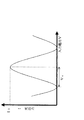
図2は、MZ型光変調器1に印加される信号源3の入力電圧(V)変化に対する、光出力(I)変化示すグラフであり、一般に、入力電圧Vが増加するに従い、光出力Iは一定の範囲を正弦波的に振動する曲線を描く。図2のように、光出力における最小点と最大点との間の入力電圧幅を半波長電圧Vπと呼び、光通信における光変調器でON/OFFスイッチング制御を行う際に、光変調器に印加する電気信号の電圧値を決定する重要な数値である。
同じ光変調器であっても、半波長電圧は光変調器に印加される電気信号の周波数に応じて変化し、しかも、近年の光通信の高速・大容量化に伴い、光変調器の駆動周波数も高周波化し、10GHzやそれ以上の周波数においても正確な半波長電圧を測定することが要求されている。
【0004】
【発明が解決しようとする課題】
半波長電圧の測定方法としては、図3のように光出力を直接観察する測定方法(従来例1)や、米国特許第6,204,954号に示す図5のような光出力の平均出力値を用いる測定方法(従来例2)などがある。
従来例1では、図3に示すように、MZ型光変調器1にレーザ光源4からの光を入射すると共に、高周波AC信号31にバイアス用のDC電源32からのバイアス電圧をバイアスT33により重畳した電圧をMZ型光変調器1に印加する。そして、MZ型光変調器1から出射される光を、高速フォトディテクタ51により検出し、検出出力をサンプリングオシロスコープ52で観測することにより行われる。
従来例1の測定方法は、MZ型光変調器1の入力電圧Vと光出力Iとの関係(V−I特性)が、図4のグラフAに示すような場合、ピーク−ピーク電圧振幅値VP−Pを持つ高周波AC信号にバイアス電圧VBが重畳されて、グラフBのような入力電圧がMZ型光変調器1に印加されると、光出力はグラフCのようになり、このグラフCの波形はサンプリングオシロスコープ52で直接観察される。
そして、この直接観察を行いながら、グラフCのピーク−ピークの振幅幅が最大となるように、VP−PとVBの電圧値を調整し、最大時のVP−Pを測定することで、MZ型光変調器1の半波長電圧Vπが求められる(Vπ=VP−P)。
しかしながら、従来例1の測定方法では、10GHzを超える高周波では、高速フォトディテクタ51など受光系の周波数特性の問題から、正確な光波形(図4のグラフC)を観察するのが困難である。このため、精密な半波長電圧の測定が出来ない。
【0005】
他方、従来例2では、図5に示すように、レーザ光が通過しているMZ型光変調器1に対して、高周波AC信号31にDC電源32からのバイアス電圧をバイアスT33により重畳した電圧を印加する。そして、MZ型光変調器1から出射される光を光カプラー53で分岐し、一方の光を光パワーメータ54に、他方の光をフォトディテェクタ55により検出し、検出出力をスペクトラムアナライザ56に導入するように構成される。
従来例2の測定方法は、MZ型光変調器1の入力電圧Vと光出力Iとの関係(V−I特性)が、図6のグラフAに示すような場合、バイアス電圧VBをV−I特性のグラフAのピーク値を示す入力電圧となるように調整(バイアス点調整)し、バイアス電圧VBにピーク−ピーク電圧振幅値VP−Pを有する高周波AC信号を重畳した場合(グラフB1)の光出力の平均出力値(グラフC1)や、高周波AC信号を付加しない場合(バイアス電圧VBのみ。グラフB2)の光出力値(グラフC2)、そして、高周波AC信号のVP−Pを各々測定する。そして、V−I特性が正弦関数になることを利用して、MZ型光変調器の半波長電圧Vπを求めることができる。
従来例2の測定方法では、高周波において精密な半波長電圧が測定できるが、MZ型光変調器のバイアス点調整が必要であり、バイアス点変動が生じて光出力に揺らぎがある場合の正確な半波長電圧の測定が難しいという問題がある。また、半波長電圧の計算に用いるパラメータが多く、計算が煩雑となっている。
【0006】
本発明は、上記のような問題点を解決し、MZ型光変調器の半波長電圧の測定において、高周波においても精密な測定が可能で、該光変調器のバイアス点変動に依存せず、しかも計算に用いるパラメータも簡潔な測定方法及び装置を提供することである。
【0007】
【課題を解決するための手段】
上記課題を解決するために、請求項1に係るマッハツェンダ型光変調器の半波長電圧測定方法は、マッハツェンダ型光変調器に、被測定周波数の高周波AC信号とモニタ用の低周波AC信号とを重畳して印加、又は両者を別々に構成された電極にそれぞれ印加し、該光変調器からの出力光の低速応答を観測することによりマッハツェンダ型光変調器の半波長電圧を測定する方法において、該高周波AC信号の電圧振幅を可変し、該モニタ用低周波AC信号による出力光の強度変化がほぼ0となる時の該高周波AC信号の電圧振幅を用いて、マッハツェンダ型光変調器の被測定周波数における半波長電圧を測定することを特徴とする。
【0008】
請求項2に係るマッハツェンダ型光変調器の半波長電圧測定方法は、請求項1に記載のマッハツェンダ型光変調器の半波長電圧測定方法において、該モニタ用低周波AC信号による出力光の強度変化がほぼ0となる時の該高周波AC信号の電圧振幅のピーク−ピーク電圧振幅値VP−Pと、マッハツェンダ型光変調器の半波長電圧値Vπとの関係が、
式 J0(πVP−P/(2Vπ))=0 (J0は0次のベッセル関数)
の関係を満足することを特徴とする。
【0009】
請求項3に係るマッハツェンダ型光変調器の半波長電圧測定方法は、請求項1に記載のマッハツェンダ型光変調器の半波長電圧測定方法において、該モニタ用低周波AC信号による出力光の強度変化がほぼ0となる時の該高周波AC信号の電圧振幅でピーク−ピーク電圧振幅値が最小となる値をVP−Pminとした場合に、マッハツェンダ型光変調器の半波長電圧値Vπが、
式 πVP−Pmin/(2Vπ)=2.405
の関係を満足することを特徴とする。
【0010】
請求項4に係るマッハツェンダ型光変調器の半波長電圧測定装置は、請求項1乃至3のいずれかに記載のマッハツェンダ型光変調器の半波長電圧測定方法を用いて、マッハツェンダ型光変調器の半波長電圧を測定可能としたことを特徴とする。
【0011】
【発明の実施の形態】
以下、本発明を好適例を用いて詳細に説明するが、本発明の範囲は、当該好適例に限定されるものではない。
本発明では、図7に示すように、MZ型光変調器1に、被測定周波数の高周波AC信号34とモニタ用の低周波AC信号35を重畳して印加、又は図9に示すように、両者を別々に構成された電極(具体的には、RF用信号電極とバイアスポート用接地電極)にそれぞれ印加し、光変調器の出力光の低速応答(低周波AC信号35に対応した変化)を、フォトディテクタ57とオシロスコープ58により観測し、この波形の観察に合わせて、高周波AC信号34の電圧振幅を調整することにより、MZ型光変調器1の半波長電圧の測定を可能とするものである。
本発明によれば、MZ型光変調器に係る測定で問題となるバイアス点の調整・制御を行う必要が無く、しかも、非常に簡便に精密な半波長電圧の測定をすることが可能となる。
【0012】
本発明の測定原理について説明する。
高周波AC信号34による位相変化をΦ1、低周波AC信号35による位相変化をΦ2とすると、MZ型光変調器1の光出力は、式(1)で表される。ただし、I0は光出力の最大値、Vp−pは高周波AC信号34のピーク−ピーク電圧振幅値、fは被測定周波数である高周波AC信号34の周波数、Vπは被測定周波数fでのMZ型光変調器1の半波長電圧を、各々意味する。
【数1】

次に、式(1)の光出力Iに係る低速応答I’は、高周波AC信号(周波数f)の時間平均をとることに相当し、式(2)のように表すことができる。
【数2】
さらに、式(2)を級数展開して整理すると、式(3)のように表すことができる。
【数3】
式(3)から、MZ型光変調器の光出力の低速応答I’は、定数項、0次のベッセル関数と余弦関数の積で表される。ここでベッセル関数で表される量は、高周波AC信号34による出力変化であり、余弦関数で表される量は、低周波AC信号35による出力変化である。
今、ベッセル関数の項を0とするような電圧Vp−pの高周波AC信号34を入力した場合、式(3)の第2項は0となり、いかなる低周波AC信号35を入力しても、光出力の低速応答I’はI0/2となり、一定の光出力となる。この様子を示したのが図8(b)である。
つまり、MZ型光変調器1に加える高周波AC信号34の電圧振幅を連続的に変化させながら、MZ型光変調器1からの出力光の低速応答をオシロスコープ58により観測し、図8(a)のように低周波AC信号の影響で光出力が変動している状態が、図8(b)のように光出力が一定となった場合に、MZ型光変調器1に入力している高周波AC信号34の電圧Vp−pを測定することにより、被測定周波数fにおける半波長電圧Vπを算出することができる。
【0016】
光出力の低速応答I’が一定となった場合のVp−pとVπとの関係は、式(3)のベッセル関数の項を0にする条件である
J0(πVP−P/(2Vπ))=0 (J0は0次のベッセル関数)
により、導出できる。
ただし、0次のベッセル関数が0となる条件は複数あるため、通常は必要な信号電圧が最小ですむ、最初に光出力が最小となるピーク−ピーク電圧振幅値VP−Pminから、πVP−Pmin/(2Vπ)=2.405の関係を用いて半波長電圧値Vπを算出する。
【0017】
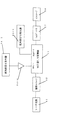
本発明に係る実験の一例を図9、10に示す。
MZ型のLN光変調器11には、レーザ光源から発生された1.55μmのレーザ光を、偏波コントローラ42を通過させて偏波状態を調整して入射させる。
LN光変調器11には、被測定周波数fの高周波AC信号とモニタ用の低周波AC信号を重畳して入力する。高周波AC信号の入力は、高周波信号発生器34−1からの高周波マイクロ波を高周波アンプ34−2により電圧振幅値を可変して、LN光変調器11の高周波用(RF)ポートに入力する。また、低周波AC信号の入力は、低周波信号発生器35−1から1kHzの正弦波をLN光変調器11のバイアス(BIAS)ポートに入力する。低周波AC信号の振幅電圧は半波長電圧の2倍以上に設定することで、常に光出力の振幅値が最大となるため、観測が容易となり、より精度の高い測定が可能となる。
LN光変調器11からの出射光は、フォトディテクタ57で光出力を検出し、検出信号をオシロスコープ58で観測する。
【0018】
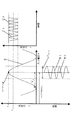
本実験例における測定結果は、各被測定周波数1GHz、5GHz、10GHzに対し、半波長電圧は4.9V、5.7V、6.4Vとなった。
図10では、この測定結果である半波長電圧を利用した場合のLN光変調器11の電気・光応答特性と、光コンポーネントアナライザによるLN光変調器11の電気・光応答特性の測定結果を比較したものである。これによると両者は非常に良く一致しており、本発明の測定は従来のものと比較し大幅に簡素化して測定しているにも拘わらず、測定結果はLN光変調器11の特性を的確に捉えていることから、本発明の測定精度は非常に優れたものと言える。
【0019】
また、本発明の測定方法及び装置は自動化することも可能であり、例えば、高周波AC信号の電圧振幅Vp−pを0から自動的に増加させ、光出力の低速応答I’の変動幅が所定値以内(所定値は0に近いほどより正確な測定結果が得られるが、測定誤差などの影響により完全に0とすることは困難なため、測定結果の用途に応じて効率的な測定が行える値を設定するのが望ましい)になった時点の値Vp−pを記憶させ、該値を用いて別途設けられた演算装置により半波長電圧Vπを算出するように構成することができる。そして、被測定周波数を順次変更しながら、同様な測定方法を繰り返すことで、任意の周波数帯域に渡る半波長電圧を自動的に測定することが可能となる。
【0020】
【発明の効果】
以上説明したように、本発明によれば、モニタ用低周波AC信号による出力光の強度変化がほぼ0となる時の高周波AC信号の電圧振幅値の最小値Vp−pminを測定し、式πVP−Pmin/(2Vπ)=2.405に代入するだけで、簡単にマッハツェンダ型光変調器の半波長電圧Vπが測定できる。
しかも、被測定周波数が高周波であっても、直接高周波波形を観測する必要がないため、精密な測定が可能であると共に、バイアス点に依存しない測定方法のため、バイアス点調整が不要な上、光変調器のバイアス点変動の影響を受けない。
さらに、半波長電圧Vπの計算に用いるパラメータもVp−pminのみでよいなど、極めて効果的なマッハツェンダ型光変調器の半波長電圧測定方法及び装置が提供できる。
【図面の簡単な説明】
【図1】 MZ型光変調器の概略図。
【図2】 MZ型光変調器のV−I特性を示すグラフ。
【図3】 従来例1の測定方法を示す概略図。
【図4】 従来例1の測定方法によるV−I特性等の関係を示すグラフ。
【図5】 従来例2の測定方法を示す概略図。
【図6】 従来例2の測定方法によるV−I特性等の関係を示すグラフ。
【図7】 本発明の測定方法を示す概略図。
【図8】 本発明の測定法による光出力の低速応答の状態変化を示すグラフ。
【図9】 本発明の実験例を示す概略図
【図10】 本発明の測定結果を利用した場合のMZ型光変調器における電気・光応答特性を示すグラフ。
【符号の説明】
1 MZ型光変調器
2 光導波路
3 信号源
4 レーザ光源
31 高周波AC信号
32 DC電源
33 バイアスT
34 高周波AC信号
34−1 高周波信号発生器
34−2 高周波アンプ
35 低周波AC信号
35−1 低周波信号発生器
36 信号加算器
41 レーザ光源
42 偏波コントローラ
51 高速フォトディテクタ
52 サンプリングオシロスコープ
53 光カプラー
54 光パワーメータ
55 フォトディテクタ
56 スペクトラムアナライザ
57 フォトディテクタ
58 オシロスコープ[0001]
BACKGROUND OF THE INVENTION
The present invention relates to a method and an apparatus for measuring a half-wave voltage (also referred to as an AC half-wave voltage) of a Mach-Zehnder type optical modulator (hereinafter referred to as an MZ type optical modulator), and particularly to high-speed, large-capacity optical fiber communication. The present invention relates to a measurement method and a measurement apparatus for measuring a half-wave voltage at a high frequency of an MZ type optical modulator corresponding to the high frequency modulation used.
[0002]
[Prior art]
An optical modulator is a main element used in a transmission unit or the like in optical communication. In particular, an MZ type optical modulator manufactured using LiNbO 3 (LN) is used in high-speed and large-capacity optical communication in recent years.・ It is used very often due to its features such as wide wavelength band and low chirp.
As shown in FIG. 1, the MZ type
[0003]
FIG. 2 is a graph showing changes in optical output (I) with respect to changes in input voltage (V) of the
Even in the same optical modulator, the half-wave voltage changes according to the frequency of the electrical signal applied to the optical modulator, and the optical modulator is driven in accordance with the recent increase in the speed and capacity of optical communication. The frequency is also increased, and it is required to measure an accurate half-wave voltage even at a frequency of 10 GHz or higher.
[0004]
[Problems to be solved by the invention]
As a measuring method of the half-wave voltage, a measuring method for directly observing the optical output (conventional example 1) as shown in FIG. 3 or an average output of the optical output as shown in FIG. 5 shown in US Pat. No. 6,204,954. There are measurement methods using values (conventional example 2).
In the conventional example 1, as shown in FIG. 3, the light from the
The measurement method of Conventional Example 1 is that when the relationship (V-I characteristic) between the input voltage V and the optical output I of the MZ type
Then, while the direct observation, the peak of the graph C - so that the amplitude width of the peak is maximum, that adjusts the voltage value of V P-P and V B, to measure V P-P at the maximum Thus, the half-wave voltage V π of the MZ type
However, in the measurement method of Conventional Example 1, it is difficult to observe an accurate optical waveform (graph C in FIG. 4) at a high frequency exceeding 10 GHz due to the problem of the frequency characteristics of the light receiving system such as the high-speed photodetector 51. For this reason, a precise half-wave voltage cannot be measured.
[0005]
On the other hand, in the conventional example 2, as shown in FIG. 5, with respect to the MZ type
Method of measuring the second conventional example, if the relationship between the input voltage V and light output I of the MZ-type optical modulator 1 (V-I characteristics), as shown in graph A in FIG. 6, the bias voltage V B V adjusted to a input voltage indicating the peak value of the graph a of -I characteristics and (bias point adjustment), a peak in the bias voltage V B - when superimposing a high-frequency AC signal having a peak voltage amplitude value V P-P ( The average output value (graph C1) of the optical output in the graph B1), the optical output value (graph C2) in the case where the high frequency AC signal is not added (only the bias voltage V B, graph B2), and the V P of the high frequency AC signal. -Measure each P. Then, by utilizing the fact that the V-I characteristic becomes a sine function, it is possible to determine the half-wave voltage V [pi of the MZ-type optical modulator.
In the measurement method of Conventional Example 2, a precise half-wave voltage can be measured at a high frequency, but it is necessary to adjust the bias point of the MZ type optical modulator, and when the bias point fluctuation occurs and the optical output fluctuates, it is accurate. There is a problem that it is difficult to measure the half-wave voltage. In addition, many parameters are used for the calculation of the half-wave voltage, and the calculation is complicated.
[0006]
The present invention solves the problems as described above, and in the measurement of the half-wave voltage of the MZ type optical modulator, precise measurement is possible even at high frequencies, and it does not depend on fluctuations in the bias point of the optical modulator, In addition, the parameters used for the calculation are to provide a simple measuring method and apparatus.
[0007]
[Means for Solving the Problems]
In order to solve the above-described problem, a method of measuring a half-wave voltage of a Mach-Zehnder optical modulator according to
[0008]
The half-wave voltage measurement method for a Mach-Zehnder optical modulator according to
Wherein J 0 (πV P-P / (2V π)) = 0 (
It is characterized by satisfying the relationship.
[0009]
A half-wave voltage measurement method for a Mach-Zehnder optical modulator according to
Formula πV P-Pmin / (2V π ) = 2.405
It is characterized by satisfying the relationship.
[0010]
A half-wave voltage measuring apparatus for a Mach-Zehnder type optical modulator according to
[0011]
DETAILED DESCRIPTION OF THE INVENTION
Hereinafter, although this invention is demonstrated in detail using a suitable example, the scope of the present invention is not limited to the said suitable example.
In the present invention, as shown in FIG. 7, a high
According to the present invention, there is no need to adjust and control the bias point, which is a problem in the measurement related to the MZ type optical modulator, and it is possible to measure the half-wave voltage with high precision and very simply. .
[0012]
The measurement principle of the present invention will be described.
Assuming that the phase change due to the high-
[Expression 1]
Next, the low-speed response I ′ related to the optical output I in Expression (1) corresponds to taking the time average of the high-frequency AC signal (frequency f), and can be expressed as Expression (2).
[Expression 2]
Furthermore, when formula (2) is expanded and arranged, it can be expressed as formula (3).
[Equation 3]
From equation (3), the slow response I ′ of the optical output of the MZ type optical modulator is expressed by the product of a constant term, a zero-order Bessel function and a cosine function. Here, the amount represented by the Bessel function is an output change due to the high
If a high -
That is, while the voltage amplitude of the high
[0016]
The relationship between V p−p and V π when the slow response I ′ of the optical output becomes constant is that J 0 (πV P−P / P ) which is a condition for setting the Bessel function term of Equation (3) to 0. (2V π )) = 0 (J 0 is a zero-order Bessel function)
Can be derived.
However, since there are a plurality of conditions in which the 0th-order Bessel function is 0, the necessary signal voltage is usually minimum. From the peak-peak voltage amplitude value V P-Pmin at which the optical output is minimized first, πV P calculating the half-wave voltage value V [pi using -Pmin / (2V π) = 2.405 relationship.
[0017]
An example of an experiment according to the present invention is shown in FIGS.
The laser light of 1.55 μm generated from the laser light source is incident on the MZ type LN optical modulator 11 after passing through the polarization controller 42 and adjusting the polarization state.
The LN optical modulator 11 receives a high frequency AC signal having a frequency f to be measured and a low frequency AC signal for monitoring superimposed on each other. The high frequency AC signal is input to the high frequency (RF) port of the LN optical modulator 11 by changing the voltage amplitude value of the high frequency microwave from the high frequency signal generator 34-1 by the high frequency amplifier 34-2. The low frequency AC signal is input by inputting a 1 kHz sine wave from the low frequency signal generator 35-1 to the bias (BIAS) port of the LN optical modulator 11. By setting the amplitude voltage of the low-frequency AC signal to at least twice the half-wave voltage, the amplitude value of the optical output is always maximized, so that observation is easy and measurement with higher accuracy is possible.
The light output from the LN optical modulator 11 is detected by a photodetector 57 and the detection signal is observed by an oscilloscope 58.
[0018]
As a result of measurement in this experimental example, the half-wave voltages were 4.9 V, 5.7 V, and 6.4 V with respect to each frequency to be measured of 1 GHz, 5 GHz, and 10 GHz.
In FIG. 10, the measurement result of the electrical / optical response characteristic of the LN optical modulator 11 when the half-wave voltage is used as the measurement result is compared with the measurement result of the electrical / optical response characteristic of the LN optical modulator 11 by the optical component analyzer. It is a thing. According to this, both agree very well, and although the measurement of the present invention is greatly simplified as compared with the conventional one, the measurement result accurately shows the characteristics of the LN optical modulator 11. Therefore, it can be said that the measurement accuracy of the present invention is very excellent.
[0019]
The measurement method and apparatus of the present invention can also be automated. For example, the voltage amplitude V p-p of the high-frequency AC signal is automatically increased from 0, and the fluctuation range of the low-speed response I ′ of the optical output is increased. Within a specified value (The closer the specified value is to 0, the more accurate measurement results can be obtained, but it is difficult to make it completely 0 due to the influence of measurement errors, etc., so efficient measurement is possible depending on the use of the measurement results It is preferable to set a value V p-p when it is desirable to set a value that can be performed, and to calculate the half-wave voltage V π by a separately provided arithmetic device using the value. . Then, by repeating the same measurement method while sequentially changing the frequency to be measured, it becomes possible to automatically measure the half-wave voltage over an arbitrary frequency band.
[0020]
【The invention's effect】
As described above, according to the present invention, the minimum value V p-pmin of the voltage amplitude value of the high-frequency AC signal when the intensity change of the output light due to the monitor low-frequency AC signal becomes almost zero is measured. only substituting the πV P-Pmin / (2V π ) = 2.405, easily half-wave voltage V [pi measurement of the Mach-Zehnder type optical modulator.
Moreover, even if the frequency to be measured is a high frequency, it is not necessary to directly observe the high frequency waveform, so that precise measurement is possible and the bias point adjustment is unnecessary because the measurement method does not depend on the bias point. Unaffected by fluctuations in bias point of optical modulator.
Furthermore, the parameters used to calculate the half-wave voltage V [pi well as it is only V p-pmin, can provide very effective Mach-Zehnder type optical modulator of the half-wave voltage measurement method and apparatus.
[Brief description of the drawings]
FIG. 1 is a schematic diagram of an MZ type optical modulator.
FIG. 2 is a graph showing VI characteristics of an MZ type optical modulator.
FIG. 3 is a schematic diagram showing a measurement method of Conventional Example 1.
4 is a graph showing the relationship of VI characteristics and the like by the measurement method of Conventional Example 1. FIG.
FIG. 5 is a schematic diagram showing a measurement method of Conventional Example 2.
6 is a graph showing the relationship of VI characteristics and the like by the measurement method of Conventional Example 2. FIG.
FIG. 7 is a schematic view showing a measurement method of the present invention.
FIG. 8 is a graph showing a change in state of a low-speed response of light output by the measurement method of the present invention.
FIG. 9 is a schematic diagram showing an experimental example of the present invention. FIG. 10 is a graph showing electrical / optical response characteristics in an MZ type optical modulator when the measurement result of the present invention is used.
[Explanation of symbols]
DESCRIPTION OF
34 High Frequency AC Signal 34-1 High Frequency Signal Generator 34-2 High Frequency Amplifier 35 Low Frequency AC Signal 35-1 Low Frequency Signal Generator 36 Signal Adder 41 Laser Light Source 42 Polarization Controller 51 High Speed Photodetector 52 Sampling Oscilloscope 53 Optical Coupler 54 Optical power meter 55 Photo detector 56 Spectrum analyzer 57 Photo detector 58 Oscilloscope
Claims (4)
該高周波AC信号の電圧振幅を可変し、該モニタ用低周波AC信号による出力光の強度変化がほぼ0となる時の該高周波AC信号の電圧振幅を用いて、マッハツェンダ型光変調器の被測定周波数における半波長電圧を測定することを特徴とするマッハツェンダ型光変調器の半波長電圧測定方法。The Mach-Zehnder type optical modulator is applied by superimposing a high frequency AC signal of the frequency to be measured and a low frequency AC signal for monitoring, or both are applied to separately configured electrodes, and output from the optical modulator In a method of measuring the half-wave voltage of a Mach-Zehnder optical modulator by observing the slow response of light,
The voltage amplitude of the high frequency AC signal is varied, and the voltage amplitude of the high frequency AC signal when the intensity change of the output light by the low frequency AC signal for monitoring becomes almost zero is used to measure the Mach-Zehnder optical modulator. A method of measuring a half-wave voltage of a Mach-Zehnder optical modulator, comprising measuring a half-wave voltage at a frequency.
式 J0(πVP−P/(2Vπ))=0 (J0は0次のベッセル関数)
の関係を満足することを特徴とするマッハツェンダ型光変調器の半波長電圧測定方法。2. The half-wave voltage measurement method for a Mach-Zehnder optical modulator according to claim 1, wherein the peak-peak of the voltage amplitude of the high-frequency AC signal when the intensity change of the output light due to the low-frequency AC signal for monitoring becomes substantially zero. and the voltage amplitude V P-P, the relationship between the half-wave voltage value V [pi Mach-Zehnder optical modulator,
Wherein J 0 (πV P-P / (2V π)) = 0 (J 0 is the zero order Bessel function)
A half-wave voltage measurement method for a Mach-Zehnder type optical modulator, characterized by satisfying the relationship:
式 πVP−Pmin/(2Vπ)=2.405
の関係を満足することを特徴とするマッハツェンダ型光変調器の半波長電圧測定方法。2. The half-wave voltage measurement method for a Mach-Zehnder optical modulator according to claim 1, wherein the peak-to-peak voltage amplitude of the high-frequency AC signal when the intensity change of the output light due to the low-frequency AC signal for monitoring becomes substantially zero. the value which the voltage amplitude becomes the minimum in the case of the V P-Pmin, the half-wave voltage value V [pi Mach-Zehnder optical modulator,
Formula πV P-Pmin / (2V π ) = 2.405
A half-wave voltage measurement method for a Mach-Zehnder type optical modulator, characterized by satisfying the relationship:
Priority Applications (8)
| Application Number | Priority Date | Filing Date | Title |
|---|---|---|---|
| JP2001243816A JP4608149B2 (en) | 2001-08-10 | 2001-08-10 | Method and apparatus for measuring half-wave voltage of Mach-Zehnder type optical modulator |
| DE60220431T DE60220431T2 (en) | 2001-08-10 | 2002-07-31 | METHOD FOR MEASURING THE HALFWAVE VOLTAGE OF AN OPTICAL MODULATOR OF THE MACH-TENDER TYPE |
| EP02755710A EP1437586B1 (en) | 2001-08-10 | 2002-07-31 | Method of measuring the half-wave voltage of a mach-zehnder type optical modulator |
| PCT/JP2002/007784 WO2003016853A1 (en) | 2001-08-10 | 2002-07-31 | Method and device for measuring half-wave voltage of mach-zehnder type optical modulator |
| AT02755710T ATE363649T1 (en) | 2001-08-10 | 2002-07-31 | METHOD FOR MEASURING THE HALF-WAVE VOLTAGE OF A MACH-ZEHNER TYPE OPTICAL MODULATOR |
| US10/486,610 US7142309B2 (en) | 2001-08-10 | 2002-07-31 | Method and device for measuring half-wave voltage of Mach-Zehnder type optical modulator |
| CNB028154800A CN1247976C (en) | 2001-08-10 | 2002-07-31 | Method and device for measuring haff-wave voltage of mach-zehnder type optical modulator |
| CA2456914A CA2456914C (en) | 2001-08-10 | 2002-07-31 | Method and device for measuring half-wave voltage of mach-zehnder type optical modulator |
Applications Claiming Priority (1)
| Application Number | Priority Date | Filing Date | Title |
|---|---|---|---|
| JP2001243816A JP4608149B2 (en) | 2001-08-10 | 2001-08-10 | Method and apparatus for measuring half-wave voltage of Mach-Zehnder type optical modulator |
Publications (2)
| Publication Number | Publication Date |
|---|---|
| JP2003057615A JP2003057615A (en) | 2003-02-26 |
| JP4608149B2 true JP4608149B2 (en) | 2011-01-05 |
Family
ID=19073849
Family Applications (1)
| Application Number | Title | Priority Date | Filing Date |
|---|---|---|---|
| JP2001243816A Expired - Fee Related JP4608149B2 (en) | 2001-08-10 | 2001-08-10 | Method and apparatus for measuring half-wave voltage of Mach-Zehnder type optical modulator |
Country Status (8)
| Country | Link |
|---|---|
| US (1) | US7142309B2 (en) |
| EP (1) | EP1437586B1 (en) |
| JP (1) | JP4608149B2 (en) |
| CN (1) | CN1247976C (en) |
| AT (1) | ATE363649T1 (en) |
| CA (1) | CA2456914C (en) |
| DE (1) | DE60220431T2 (en) |
| WO (1) | WO2003016853A1 (en) |
Families Citing this family (10)
| Publication number | Priority date | Publication date | Assignee | Title |
|---|---|---|---|---|
| JP2005127783A (en) * | 2003-10-22 | 2005-05-19 | Yokogawa Electric Corp | Electric signal observation device and electric signal sampling device and method for the same |
| US7805026B2 (en) * | 2007-10-09 | 2010-09-28 | Alcatel-Lucent Usa Inc. | Resonator-assisted control of radio-frequency response in an optical modulator |
| US8014676B2 (en) * | 2008-02-22 | 2011-09-06 | Alcatel Lucent | CMOS-compatible tunable microwave photonic band-stop filter |
| CN101621329B (en) * | 2008-07-03 | 2013-01-23 | 华为技术有限公司 | Method and system for measuring bias points of double-parallel modulator |
| CN102575971B (en) * | 2009-09-07 | 2015-05-27 | 独立行政法人情报通信研究机构 | Method for evaluating characteristic of optical modulator having mach-zehnder interferometer |
| CN102798750B (en) * | 2012-08-17 | 2015-04-29 | 华中科技大学 | Method and system for measuring half-wave voltage of electro-optical modulator |
| US10684311B2 (en) * | 2017-05-10 | 2020-06-16 | Tektronix, Inc. | High input impedance electro-optic sensor |
| CN111707361B (en) * | 2020-06-28 | 2023-04-11 | 中国电子科技集团公司第四十四研究所 | Method for measuring half-wave voltage of M-Z type light intensity modulator |
| CN111707360B (en) * | 2020-06-28 | 2023-03-31 | 中国电子科技集团公司第四十四研究所 | Method for measuring half-wave voltage of M-Z type light intensity modulator |
| CN114362822B (en) * | 2021-12-08 | 2023-08-22 | 中国人民解放军战略支援部队信息工程大学 | Based on LiNbO 3 Natural light communication method of body modulator |
Citations (1)
| Publication number | Priority date | Publication date | Assignee | Title |
|---|---|---|---|---|
| JPH03123828A (en) * | 1989-10-06 | 1991-05-27 | Nippon Telegr & Teleph Corp <Ntt> | Instrument and method for measuring characteristic of optical phase modulator |
Family Cites Families (8)
| Publication number | Priority date | Publication date | Assignee | Title |
|---|---|---|---|---|
| JPH03139653A (en) * | 1989-10-26 | 1991-06-13 | Fuji Photo Film Co Ltd | Original plate for electrophotographic type planographic printing |
| JP2792482B2 (en) * | 1995-09-28 | 1998-09-03 | 日本電気株式会社 | Semiconductor Mach-Zehnder modulator |
| JPH10148801A (en) * | 1996-11-21 | 1998-06-02 | Toshiba Corp | Optical modulation device by external modulation system |
| JP3913856B2 (en) * | 1997-08-28 | 2007-05-09 | 富士通株式会社 | Optical pulse generation device, dispersion measurement device, dispersion compensation device, and dispersion measurement method |
| US6204954B1 (en) * | 1999-09-22 | 2001-03-20 | Nortel Networks Limited | Technique for measuring the Vpi-AC of a mach-zehnder modulator |
| JP2001154164A (en) * | 1999-11-25 | 2001-06-08 | Nec Corp | Optical modulator and optical modulating method |
| JP3693872B2 (en) * | 1999-12-02 | 2005-09-14 | 住友大阪セメント株式会社 | Light modulation apparatus and method |
| US6956653B1 (en) * | 2000-06-27 | 2005-10-18 | Lockheed Martin Corporation | Dual electrooptic waveguide interferometer |
-
2001
- 2001-08-10 JP JP2001243816A patent/JP4608149B2/en not_active Expired - Fee Related
-
2002
- 2002-07-31 DE DE60220431T patent/DE60220431T2/en not_active Expired - Lifetime
- 2002-07-31 US US10/486,610 patent/US7142309B2/en not_active Expired - Fee Related
- 2002-07-31 CN CNB028154800A patent/CN1247976C/en not_active Expired - Fee Related
- 2002-07-31 CA CA2456914A patent/CA2456914C/en not_active Expired - Fee Related
- 2002-07-31 AT AT02755710T patent/ATE363649T1/en not_active IP Right Cessation
- 2002-07-31 WO PCT/JP2002/007784 patent/WO2003016853A1/en active IP Right Grant
- 2002-07-31 EP EP02755710A patent/EP1437586B1/en not_active Expired - Lifetime
Patent Citations (1)
| Publication number | Priority date | Publication date | Assignee | Title |
|---|---|---|---|---|
| JPH03123828A (en) * | 1989-10-06 | 1991-05-27 | Nippon Telegr & Teleph Corp <Ntt> | Instrument and method for measuring characteristic of optical phase modulator |
Also Published As
| Publication number | Publication date |
|---|---|
| CA2456914C (en) | 2011-04-12 |
| EP1437586A1 (en) | 2004-07-14 |
| DE60220431D1 (en) | 2007-07-12 |
| CN1539078A (en) | 2004-10-20 |
| DE60220431T2 (en) | 2008-03-13 |
| ATE363649T1 (en) | 2007-06-15 |
| EP1437586A4 (en) | 2006-05-10 |
| JP2003057615A (en) | 2003-02-26 |
| CN1247976C (en) | 2006-03-29 |
| CA2456914A1 (en) | 2003-02-27 |
| EP1437586B1 (en) | 2007-05-30 |
| US20040247219A1 (en) | 2004-12-09 |
| US7142309B2 (en) | 2006-11-28 |
| WO2003016853A1 (en) | 2003-02-27 |
Similar Documents
| Publication | Publication Date | Title |
|---|---|---|
| JP4949496B2 (en) | Optical frequency comb generator, optical pulse generator using the same, optical frequency comb generator, and optical pulse generator using the same | |
| JP2866186B2 (en) | Electromagnetic field strength measuring device | |
| CN110017967B (en) | Phase comparison-based chirp parameter testing method for electro-optic intensity modulator | |
| JP4608149B2 (en) | Method and apparatus for measuring half-wave voltage of Mach-Zehnder type optical modulator | |
| EP2309323B1 (en) | Method for evaluating characteristics of an optical modulator including plural mach-zehnder interferometers | |
| JP2619981B2 (en) | Electromagnetic field strength measuring device | |
| JP5137042B2 (en) | Evaluation method of optical modulator with high accuracy Mach-Zehnder interferometer | |
| US6204954B1 (en) | Technique for measuring the Vpi-AC of a mach-zehnder modulator | |
| JP2023031312A (en) | Coupling devices and methods, wavelength locking systems and methods, and phase unwrapping systems and methods | |
| JP3866082B2 (en) | Method and apparatus for measuring characteristics of optical modulator | |
| CN110411715B (en) | Device and method for determining half-wave voltage of AMZI phase modulator | |
| JP3538619B2 (en) | Method for evaluating characteristics of optical modulator and method for controlling high-frequency oscillator using the same | |
| JP6988076B2 (en) | Optical modulator and light modulator control method | |
| JP2004302238A (en) | Optical ssb modulating device | |
| CN113325216B (en) | Method and system for measuring half-wave voltage of electro-optic phase modulator | |
| US5022754A (en) | Determining the wavelength of optical radiation | |
| Jung | Integrated-Optic Electric-Field Sensor Utilizing a Ti: LiNbO 3 Y-fed Balanced-Bridge Mach-Zehnder Interferometric Modulator With a Segmented Dipole Antenna | |
| JPH0321916A (en) | Optical modulator | |
| JP5640195B2 (en) | Evaluation method of optical modulator with multiple Mach-Zehnder interferometers | |
| JP3435583B2 (en) | Electric field sensor | |
| CN113608009A (en) | Half-wave voltage measuring device and method | |
| JPH03269226A (en) | Operating point stabilizing method of optical interferometer, frequency modulating efficiency measuring device of semiconductor laser and light transmitter used in this method | |
| JPH03123828A (en) | Instrument and method for measuring characteristic of optical phase modulator | |
| JPH04290940A (en) | Method and device for measuring characteristics of light modulator | |
| KR19990084900A (en) | Apparatus and method for measuring transient chirp of optical modulator using interference filter |
Legal Events
| Date | Code | Title | Description |
|---|---|---|---|
| A621 | Written request for application examination |
Free format text: JAPANESE INTERMEDIATE CODE: A621 Effective date: 20080313 |
|
| TRDD | Decision of grant or rejection written | ||
| A01 | Written decision to grant a patent or to grant a registration (utility model) |
Free format text: JAPANESE INTERMEDIATE CODE: A01 Effective date: 20101005 |
|
| A01 | Written decision to grant a patent or to grant a registration (utility model) |
Free format text: JAPANESE INTERMEDIATE CODE: A01 |
|
| A61 | First payment of annual fees (during grant procedure) |
Free format text: JAPANESE INTERMEDIATE CODE: A61 Effective date: 20101008 |
|
| R150 | Certificate of patent or registration of utility model |
Free format text: JAPANESE INTERMEDIATE CODE: R150 |
|
| FPAY | Renewal fee payment (event date is renewal date of database) |
Free format text: PAYMENT UNTIL: 20131015 Year of fee payment: 3 |
|
| LAPS | Cancellation because of no payment of annual fees |