JP4605943B2 - Cogeneration system operation method - Google Patents
Cogeneration system operation method Download PDFInfo
- Publication number
- JP4605943B2 JP4605943B2 JP2001187998A JP2001187998A JP4605943B2 JP 4605943 B2 JP4605943 B2 JP 4605943B2 JP 2001187998 A JP2001187998 A JP 2001187998A JP 2001187998 A JP2001187998 A JP 2001187998A JP 4605943 B2 JP4605943 B2 JP 4605943B2
- Authority
- JP
- Japan
- Prior art keywords
- power
- heat
- amount
- demand
- power generation
- Prior art date
- Legal status (The legal status is an assumption and is not a legal conclusion. Google has not performed a legal analysis and makes no representation as to the accuracy of the status listed.)
- Expired - Fee Related
Links
Images

Classifications
-
- Y—GENERAL TAGGING OF NEW TECHNOLOGICAL DEVELOPMENTS; GENERAL TAGGING OF CROSS-SECTIONAL TECHNOLOGIES SPANNING OVER SEVERAL SECTIONS OF THE IPC; TECHNICAL SUBJECTS COVERED BY FORMER USPC CROSS-REFERENCE ART COLLECTIONS [XRACs] AND DIGESTS
- Y02—TECHNOLOGIES OR APPLICATIONS FOR MITIGATION OR ADAPTATION AGAINST CLIMATE CHANGE
- Y02E—REDUCTION OF GREENHOUSE GAS [GHG] EMISSIONS, RELATED TO ENERGY GENERATION, TRANSMISSION OR DISTRIBUTION
- Y02E20/00—Combustion technologies with mitigation potential
- Y02E20/14—Combined heat and power generation [CHP]
-
- Y—GENERAL TAGGING OF NEW TECHNOLOGICAL DEVELOPMENTS; GENERAL TAGGING OF CROSS-SECTIONAL TECHNOLOGIES SPANNING OVER SEVERAL SECTIONS OF THE IPC; TECHNICAL SUBJECTS COVERED BY FORMER USPC CROSS-REFERENCE ART COLLECTIONS [XRACs] AND DIGESTS
- Y02—TECHNOLOGIES OR APPLICATIONS FOR MITIGATION OR ADAPTATION AGAINST CLIMATE CHANGE
- Y02E—REDUCTION OF GREENHOUSE GAS [GHG] EMISSIONS, RELATED TO ENERGY GENERATION, TRANSMISSION OR DISTRIBUTION
- Y02E60/00—Enabling technologies; Technologies with a potential or indirect contribution to GHG emissions mitigation
- Y02E60/30—Hydrogen technology
- Y02E60/50—Fuel cells
-
- Y—GENERAL TAGGING OF NEW TECHNOLOGICAL DEVELOPMENTS; GENERAL TAGGING OF CROSS-SECTIONAL TECHNOLOGIES SPANNING OVER SEVERAL SECTIONS OF THE IPC; TECHNICAL SUBJECTS COVERED BY FORMER USPC CROSS-REFERENCE ART COLLECTIONS [XRACs] AND DIGESTS
- Y02—TECHNOLOGIES OR APPLICATIONS FOR MITIGATION OR ADAPTATION AGAINST CLIMATE CHANGE
- Y02T—CLIMATE CHANGE MITIGATION TECHNOLOGIES RELATED TO TRANSPORTATION
- Y02T10/00—Road transport of goods or passengers
- Y02T10/10—Internal combustion engine [ICE] based vehicles
- Y02T10/12—Improving ICE efficiencies
Description
【0001】
【発明の属する技術分野】
本発明は、エンジンと発電機とを一体化したものとか燃料電池といったような、電力と熱とを発生する熱電併給装置を設け、電力と熱の両方を得るように構成したコージェネレーションシステムの運転方法に関する。
【0002】
【従来の技術】
この種のものとして、電力需要に追従して運転するように構成したものがあったが、熱電併給装置で発生した熱の総量が熱需要量よりも必要以上に多いと、余剰の熱を捨てることになって無駄である。
【0003】
そこで、熱電併給装置で発生した熱を貯める蓄熱タンクを設け、その蓄熱タンク内の上下の所定箇所に温度センサを設け、その温度変化に基づいて蓄熱タンク内に温水が満杯になったかほぼ空になったかを判別させ、熱電併給装置の運転を制御し、熱需要に対応できるようにしている。
【0004】
【発明が解決しようとする課題】
しかしながら、実際に熱を必要としない場合でも蓄熱タンク内に熱を貯めることになり、その貯めた熱を消費するまでの時間が長いと、蓄熱タンクからの放熱量が多くなり、この放熱ロスのために省エネルギー性が低下する欠点があった。
【0005】
運転形態としては、定格発電量での運転、定格以下の部分は電力需要に追従する運転、更には複数段の発電量での運転があるが、いずれにおいても、放熱ロスを少なくするために、熱を消費するまでの時間が短くなるように熱電併給装置を運転しようとすると、電力需要が少ないときに運転することになって、見掛け上の発電効率または発電効率が低下してしまい、省エネルギー性がかえって低下する問題がある。
【0006】
逆に、発電効率を重視し、発電効率が高い状態で熱電併給装置を運転しようとすると、前述同様に、放熱ロスのために、省エネルギー性が低下する問題がある。
【0007】
また、コージェネレーションシステムを構築する場合、敷地面積や断熱構成などのコスト面から蓄熱タンクが容量的に制約を受けざるを得ず、蓄熱量に限界があるために、わずかな熱量不足に起因して熱電併給装置を運転しなければならないなど、省エネルギー性を低下する欠点があった。
【0008】
本発明は、このような事情に鑑みてなされたものであって、請求項1、請求項2、請求項7および請求項8に係る発明は、見掛け上の発電効率を極力高くするとともに放熱ロスを極力少なくする状態で熱電併給装置を運転し、かつ、補助加熱手段を利用して、省エネルギー性を良好に向上できるようにすることを目的とし、請求項3、請求項4、請求項5、請求項6、請求項9および請求項10に係る発明は、発電効率を極力高くするとともに放熱ロスを極力少なくする状態で熱電併給装置を運転し、かつ、補助加熱手段を利用して、省エネルギー性を良好に向上できるようにすることを目的とし、請求項11に係る発明は、耐久性を向上できるようにすることを目的とする。
【0009】
【課題を解決するための手段】
請求項1に係る発明のコージェネレーションシステムの運転方法は、上述のような目的を達成するために、
定格発電量の電力と熱とを発生する熱電併給装置と、
前記熱電併給装置で発生した熱を貯める蓄熱タンクと、
前記熱電併給装置で発生した電力を熱に変換する電熱変換手段と、
不足分の熱量を補う補助加熱手段と、
所定時間を1周期として、その1周期内の熱需要および電力需要それぞれの経時的変化を予め特定する需要変化特定手段と、
不足分の電力を投入可能な買電手段とを備え、
前記1周期内での熱需要分またはその大半に相当する量の熱を前記熱電併給装置により前記1周期内で発生させて消費するとともに、余剰となった熱を次の周期で消費することを許容し、かつ、不足分の熱量を前記補助加熱手段で補い、前記1周期を設定時間間隔ごとに分割して、各分割時間それぞれにおいて前記熱電併給装置を運転する状態と停止する状態とを想定し、前記蓄熱タンク内の蓄熱量が0以上でかつ最大蓄熱量を越えないようにして、全体の一次エネルギーの換算値が最小となる組み合わせの最適運転状態を求め、求められた最適運転状態によって、前記熱電併給装置を定格発電量で運転するとともに電力需要が定格発電量の電力よりも小さいときの余剰電力を前記電熱変換手段で熱に変換することを特徴としている。
また、請求項2に係る発明のコージェネレーションシステムの運転方法は、上述のような目的を達成するために、
請求項1に記載のコージェネレーションシステムの運転方法において、
所定時間を1周期Tとして、その1周期T内の熱需要および電力需要それぞれの経時的変化を予め特定する需要変化特定手段を備え、
前記1周期T内での熱需要分またはその大半に相当する量の熱を前記熱電併給装置により前記1周期T内で発生させて消費するとともに、余剰となった熱を次の周期で消費することを許容し、かつ、不足分の熱量を前記補助加熱手段で補い、前記1周期Tを設定時間間隔dごとに分割して、各分割時間それぞれにおいて前記熱電併給装置を運転する状態と停止する状態とを想定し、前記蓄熱タンク内の蓄熱量の変動値S(t+n・d)が常に下記条件式(1)を満たすとともに、下記一次エネルギーの換算値PE[式(4)]が最小となる組み合わせの最適運転状態を求め、求められた最適運転状態によって、前記熱電併給装置を定格発電量で運転するとともに電力需要が定格発電量の電力よりも小さいときの余剰電力を前記電熱変換手段で熱に変換することを特徴としている。
【数30】

HTn は分割時間間隔d内での取得熱量を示し、下記(2)式で表される。
【数31】
【数32】
e(t’)≧Fであれば、En (t’)=F
ここで、En (t’)は、負荷電力が定格発電量の電力を越える場合は定格電力量となり、負荷電力が定格電力より小さい場合はその負荷電力量となる電力量であり、e(t’)は、予め特定された電力需要(負荷電力)の経時的変化を示す関数である。
上記(2)式において、BO(t’)は、熱量不足を生じた際に、その不足分を補うように補助加熱手段を起動する場合の関数を示している。
PE=ΣPEn =ΣGIn ・α+ΣBIn ・α’+ΣBEn ・β……(4)
ここで、ΣPEn は、n=1〜T/dの一次エネルギーの総和である。GInは熱電併給装置の運転に要する燃料供給量であり、次式(5)で表され、また、αは燃料の一次エネルギーへの換算値であり、ΣGIn ・αはn=1〜T/dの総和を求めている。また、BIn は補助加熱手段の運転に要する燃料供給量であり、α’は燃料の一次エネルギーへの換算値であり、ΣBIn ・α’はn=1〜T/dの総和を求めている。
【数33】
ΣBEn は、1周期Tとなる所定時間T内での不足分の電力の投入量であり、次式(6)で表され、また、βは電力の一次エネルギーへの換算値であり、n=1〜T/dの総和を求めている。
【数34】
【数35】
【0010】
また、請求項3に係る発明のコージェネレーションシステムの運転方法は、前述のような目的を達成するために、
負荷電力が定格発電量より少ない場合に負荷電力に合わせて運転することができる電力と熱とを発生する熱電併給装置と、
前記熱電併給装置で発生した熱を貯める蓄熱タンクと、
不足分の熱量を補う補助加熱手段と、
所定時間を1周期として、その1周期内の熱需要および電力需要それぞれの経時的変化を予め特定する需要変化特定手段と、
不足分の電力を投入可能な買電手段とを備え、
前記1周期内での熱需要分に相当する量の熱を前記熱電併給装置により前記1周期内で発生させて消費するとともに、余剰となった熱を次の周期で消費することを許容し、かつ、不足分の熱量を前記補助加熱手段で補い、前記1周期を設定時間間隔ごとに分割して、各分割時間それぞれにおいて前記熱電併給装置を運転する状態と停止する状態とを想定し、前記蓄熱タンク内の蓄熱量が0以上でかつ最大蓄熱量を越えないようにして、全体の一次エネルギーの換算値が最小となる組み合わせの最適運転状態を求め、求められた最適運転状態によって、前記熱電併給装置を定格発電量で運転するとともに電力需要が定格発電量の電力よりも小さいときには電力需要の変化に追従させて運転することを特徴としている。
また、請求項4に係る発明のコージェネレーションシステムの運転方法は、前述のような目的を達成するために、
所定時間を1周期Tとして、その1周期T内の熱需要および電力需要それぞれの経時的変化を予め特定する需要変化特定手段を備え、
前記1周期T内での熱需要分に相当する量の熱を前記熱電併給装置により前記1周期T内で発生させて消費するとともに、余剰となった熱を次の周期で消費することを許容し、かつ、不足分の熱量を前記補助加熱手段で補い、前記1周期Tを設定時間間隔dごとに分割して、各分割時間それぞれにおいて前記熱電併給装置を運転する状態と停止する状態とを想定し、前記蓄熱タンク内の蓄熱量の変動値S(t+n・d)が常に下記条件式(8)を満たすとともに、下記一次エネルギーの換算値PE[式(10)]が最小となる組み合わせの最適運転状態を求め、求められた最適運転状態によって、前記熱電併給装置を定格発電量で運転するとともに電力需要が定格発電量の電力よりも小さいときには電力需要の変化に追従させて運転することを特徴としている。
【数36】
HTn は分割時間間隔d内での取得熱量を示し、下記(9)式で表される。
【数37】
また、BO(t’)は、熱量不足を生じた際に、その不足分を補うように補助加熱手段を起動する場合の関数を示している。
PE=ΣPEn =ΣGIn ・α+ΣBIn ・α’+ΣBEn ・β……(10) ここで、ΣPEn は、n=1〜T/dの一次エネルギーの総和である。GInは熱電併給装置の運転に要する燃料供給量であり、次式(5a)で表され、また、αは燃料の一次エネルギーへの換算値であり、ΣGIn ・αはn=1〜T/dの総和を求めている。また、BIn は補助加熱手段の運転に要する燃料供給量であり、α’は燃料の一次エネルギーへの換算値であり、ΣBIn ・α’はn=1〜T/dの総和を求めている。
【数38】
ΣBEn は、1周期Tとなる所定時間T内での不足分の電力の投入量であり、次式(11)で表され、また、βは電力の一次エネルギーへの換算値であり、n=1〜T/dの総和を求めている。
【数39】
【数40】
【0011】
また、請求項5に係る発明のコージェネレーションシステムの運転方法は、前述のような目的を達成するために、
複数段に設定した発電量で運転して設定発電量の電力と熱とを発生する熱電併給装置と、
前記熱電併給装置で発生した熱を貯める蓄熱タンクと、
前記熱電併給装置で発生した電力を熱に変換する電熱変換手段と、
不足分の熱量を補う補助加熱手段と、
所定時間を1周期として、その1周期および次の1周期それぞれ内の熱需要および電力需要それぞれの経時的変化を予め特定する需要変化特定手段と、
不足分の電力を投入可能な買電手段とを備え、
前記1周期内での熱需要分に相当する量の熱を前記熱電併給装置により前記1周期内で発生させて消費するとともに、余剰となった熱を次の周期で消費することを許容し、かつ、不足分の熱量を前記補助加熱手段で補い、前記1周期を設定時間間隔ごとに分割して、各分割時間それぞれにおいて前記熱電併給装置を複数段の設定発電量それぞれで運転する状態と停止する状態とを想定し、前記蓄熱タンク内の蓄熱量が0以上でかつ最大蓄熱量を越えないようにして、全体の一次エネルギーの換算値が最小となる組み合わせの最適運転状態を求め、求められた最適運転状態によって、前記熱電併給装置を複数段の定格発電量で運転するとともに電力需要が設定発電量よりも小さいときの余剰電力を前記電熱変換手段で熱に変換することを特徴としている。
また、請求項6に係る発明のコージェネレーションシステムの運転方法は、前述のような目的を達成するために、
請求項5に記載のコージェネレーションシステムの運転方法において、
所定時間を1周期Tとして、その1周期Tおよび次の1周期Tそれぞれ内の熱需要および電力需要それぞれの経時的変化を予め特定する需要変化特定手段を備え、
複数段に設定した発電量で運転して設定発電量の電力と熱とを発生する熱電併給装置と、
前記熱電併給装置で発生した熱を貯める蓄熱タンクと、
前記熱電併給装置で発生した電力を熱に変換する電熱変換手段と、
不足分の熱量を補う補助加熱手段と、
所定時間を1周期Tとして、その1周期Tおよび次の1周期Tそれぞれ内の熱需要および電力需要それぞれの経時的変化を予め特定する需要変化特定手段と、 不足分の電力を投入可能な買電手段とを備え、
前記1周期T内での熱需要分に相当する量の熱を前記熱電併給装置により前記1周期T内で発生させて消費するとともに、余剰となった熱を次の周期で消費することを許容し、かつ、不足分の熱量を前記補助加熱手段で補い、前記1周期Tを設定時間間隔dごとに分割して、各分割時間それぞれにおいて前記熱電併給装置を複数段の設定発電量それぞれで運転する状態と停止する状態とを想定し、前記蓄熱タンク内の蓄熱量の変動値S(t+n・d)が常に下記条件式(13)を満たすとともに、下記一次エネルギーの換算値PE[式(16)]が最小となる組み合わせの最適運転状態を求め、求められた最適運転状態によって、前記熱電併給装置を複数段の定格発電量で運転するとともに電力需要が設定発電量よりも小さいときの余剰電力を前記電熱変換手段で熱に変換することを特徴としている。
【数41】
HTn は分割時間間隔d内での取得熱量を示し、下記(14)式で表される。
【数42】
【数43】
e(t’)≧Fm であれば、En (t’)=Fm
ここで、En (t’)は、負荷電力が設定発電量Fm を越える場合は設定電力量となり、負荷電力が設定発電量Fm より小さい場合はその負荷電力量となる電力量であり、e(t’)は、予め特定された電力需要(負荷電力)の経時的変化を示す関数である。
上記(14)式において、BO(t’)は、熱量不足を生じた際に、その不足分を補うように補助加熱手段を起動する場合の関数を示している。
PE=ΣPEn =ΣGIn ・α+ΣBIn ・α’+ΣBEn ・β……(16)
ここで、ΣPEn は、n=1〜T/dの一次エネルギーの総和である。GInは熱電併給装置の運転に要する燃料供給量であり、次式(17)で表され、また、αは燃料の一次エネルギーへの換算値であり、ΣGIn ・αはn=1〜T/dの総和を求めている。また、BIn は補助加熱手段の運転に要する燃料供給量であり、α’は燃料の一次エネルギーへの換算値であり、ΣBIn ・α’はn=1〜T/dの総和を求めている。
【数44】
ΣBEn は、1周期Tとなる所定時間T内での不足分の電力の投入量であり、次式(18)で表され、また、βは電力の一次エネルギーへの換算値であり、n=1〜T/dの総和を求めている。
【数45】
【数46】
【0012】
また、請求項7に係る発明のコージェネレーションシステムの運転方法は、前述のような目的を達成するために、
定格発電量の電力と熱とを発生する熱電併給装置と、
前記熱電併給装置で発生した熱を貯める蓄熱タンクと、
前記熱電併給装置で発生した電力を第3者に売る売電手段と、
不足分の熱量を補う補助加熱手段と、
所定時間を1周期として、その1周期内の熱需要および電力需要それぞれの経時的変化を予め特定する需要変化特定手段と、
不足分の電力を投入可能な買電手段とを備え、
前記1周期内での熱需要分またはその大半に相当する量の熱を前記熱電併給装置により前記1周期内で発生させて消費するとともに、余剰となった熱を次の周期で消費することを許容し、かつ、不足分の熱量を前記補助加熱手段で補い、前記1周期を設定時間間隔ごとに分割して、各分割時間それぞれにおいて前記熱電併給装置を運転する状態と停止する状態とを想定し、前記蓄熱タンク内の蓄熱量の変動値が0以上でかつ最大蓄熱量を越えないようにして、全体の一次エネルギーの換算値が最小となる組み合わせの最適運転状態を求め、求められた最適運転状態によって、前記熱電併給装置を定格発電量で運転するとともに電力需要が定格発電量の電力よりも小さいときの余剰電力を前記売電手段で第3者に売ることを特徴としている。
また、請求項8に係る発明のコージェネレーションシステムの運転方法は、前述のような目的を達成するために、
所定時間を1周期Tとして、その1周期T内の熱需要および電力需要それぞれの経時的変化を予め特定する需要変化特定手段を備え、
前記1周期T内での熱需要分またはその大半に相当する量の熱を前記熱電併給装置により前記1周期T内で発生させて消費するとともに、余剰となった熱を次の周期で消費することを許容し、かつ、不足分の熱量を前記補助加熱手段で補い、前記1周期Tを設定時間間隔dごとに分割して、各分割時間それぞれにおいて前記熱電併給装置を運転する状態と停止する状態とを想定し、前記蓄熱タンク内の蓄熱量の変動値S(t+n・d)が常に下記条件式(20)を満たすとともに、下記一次エネルギーの換算値PE[式(22)]が最小となる組み合わせの最適運転状態を求め、求められた最適運転状態によって、前記熱電併給装置を定格発電量で運転するとともに電力需要が定格発電量の電力よりも小さいときの余剰電力を前記売電手段で第3者に売ることを特徴としている。
【数47】
HTn は分割時間間隔d内での取得熱量を示し、下記(21)式で表される。
【数48】
上記(21)式において、BO(t’)は、熱量不足を生じた際に、その不足分を補うように補助加熱手段を起動する場合の関数を示している。
PE=ΣPEn
=ΣGIn ・α+ΣBIn ・α’+ΣBEn ・β−ΣSEn ・γ…(22)
ここで、ΣPEn は、n=1〜T/dの一次エネルギーの総和である。GInは熱電併給装置の運転に要する燃料供給量であり、次式(23)で表され、また、αは燃料の一次エネルギーへの換算値であり、ΣGIn ・αはn=1〜T/dの総和を求めている。また、BIn は補助加熱手段の運転に要する燃料供給量であり、α’は燃料の一次エネルギーへの換算値であり、ΣBIn ・α’はn=1〜T/dの総和を求めている。
【数49】
ΣBEn は、1周期Tとなる所定時間T内での不足分の電力の投入量であり、次式(24)で表され、また、βは電力の一次エネルギーへの換算値であり、n=1〜T/dの総和を求めている。
【数50】
【数51】
【数52】
e(t’)≧Fであれば、En (t’)=F
ここで、En (t’)は、負荷電力が定格発電量の電力を越える場合は定格電力量となり、負荷電力が定格電力より小さい場合はその負荷電力量となる電力量であり、e(t’)は、予め特定された電力需要(負荷電力)の経時的変化を示す関数である。
【0013】
また、請求項9に係る発明のコージェネレーションシステムの運転方法は、前述のような目的を達成するために、
複数段に設定した発電量で運転して設定発電量の電力と熱とを発生する熱電併給装置と、
前記熱電併給装置で発生した熱を貯める蓄熱タンクと、
前記熱電併給装置で発生した電力を第3者に売る売電手段と、
不足分の熱量を補う補助加熱手段と、
所定時間を1周期として、その1周期および次の1周期それぞれ内の熱需要および電力需要それぞれの経時的変化を予め特定する需要変化特定手段と、
不足分の電力を投入可能な買電手段とを備え、
前記1周期内での熱需要分に相当する量の熱を前記熱電併給装置により前記1周期内で発生させて消費するとともに、余剰となった熱を次の周期で消費することを許容し、かつ、不足分の熱量を前記補助加熱手段で補い、前記1周期を設定時間間隔ごとに分割して、各分割時間それぞれにおいて前記熱電併給装置を複数段の設定発電量それぞれで運転する状態と停止する状態とを想定し、前記蓄熱タンク内の蓄熱量が0以上でかつ最大蓄熱量を越えないようにして、全体の一次エネルギーの換算値が最小となる組み合わせの最適運転状態を求め、求められた最適運転状態によって、前記熱電併給装置を複数段の定格発電量で運転するとともに電力需要が設定発電量よりも小さいときの余剰電力を前記売電手段で第3者に売ることを特徴としている。
また、請求項10に係る発明のコージェネレーションシステムの運転方法は、前述のような目的を達成するために、
所定時間を1周期Tとして、その1周期Tおよび次の1周期Tそれぞれ内の熱需要および電力需要それぞれの経時的変化を予め特定する需要変化特定手段を備え、
前記1周期T内での熱需要分に相当する量の熱を前記熱電併給装置により前記1周期T内で発生させて消費するとともに、余剰となった熱を次の周期で消費することを許容し、かつ、不足分の熱量を前記補助加熱手段で補い、前記1周期Tを設定時間間隔dごとに分割して、各分割時間それぞれにおいて前記熱電併給装置を複数段の設定発電量それぞれで運転する状態と停止する状態とを想定し、前記蓄熱タンク内の蓄熱量の変動値S(t+n・d)が常に下記条件式(27)を満たすとともに、下記一次エネルギーの換算値PE[式(29)]が最小となる組み合わせの最適運転状態を求め、求められた最適運転状態によって、前記熱電併給装置を複数段の定格発電量で運転するとともに電力需要が設定発電量よりも小さいときの余剰電力を前記売電手段で第3者に売ることを特徴としている。
【数53】
HTn は分割時間間隔d内での取得熱量を示し、下記(28)式で表される。
【数54】
上記(28)式において、BO(t’)は、熱量不足を生じた際に、その不足分を補うように補助加熱手段を起動する場合の関数を示している。
PE=ΣPEn
=ΣGIn ・α+ΣBIn ・α’+ΣBEn ・β−ΣSEn ・γ…(29)
ここで、ΣPEn は、n=1〜T/dの一次エネルギーの総和である。GInは熱電併給装置の運転に要する燃料供給量であり、次式(30)で表され、また、αは燃料の一次エネルギーへの換算値であり、ΣGIn ・αはn=1〜T/dの総和を求めている。また、BIn は補助加熱手段の運転に要する燃料供給量であり、α’は燃料の一次エネルギーへの換算値であり、ΣBIn ・α’はn=1〜T/dの総和を求めている。
【数55】
ΣBEn は、1周期Tとなる所定時間T内での不足分の電力の投入量であり、次式(31)で表され、また、βは電力の一次エネルギーへの換算値であり、n=1〜T/dの総和を求めている。
【数56】
【数57】
【数58】
e(t’)≧Fm であれば、En (t’)=F
ここで、En (t’)は、負荷電力が設定発電量Fm を越える場合は設定電力量となり、負荷電力が設定発電量Fm より小さい場合はその負荷電力量となる電力量であり、e(t’)は、予め特定された電力需要(負荷電力)の経時的変化を示す関数である。
【0014】
また、請求項11に係る発明は、前述のような目的を達成するために、
請求項1、請求項2、請求項3、請求項4、請求項5、請求項6、請求項7、請求項8、請求項9、請求項10のいずれかに記載のコージェネレーションシステムの運転方法において、
熱電併給装置の1周期内における発停回数を設定する発停回数設定手段を備え、前記熱電併給装置の1周期内における発停回数が設定回数以下で一次エネルギーの換算値PEが最小となる組み合わせの最適運転状態を求めるように構成する。
【0015】
【作用】
請求項1および請求項2に係る発明のコージェネレーションシステムの運転方法の構成によれば、例えば、1日間など、1周期となる所定時間内において、熱電併給装置を定格発電量で運転して発電し、電力需要が定格発電量の電力よりも小さいときの電力需要を越える余剰の電力を電熱変換手段によって熱に変換し、不足分の電力を買電手段で賄うとともに、変換した熱と熱電併給装置で発生した熱によって熱需要を賄い、かつ、後で必要とする熱を蓄熱タンクに貯めて熱需要に応じるとともに、不足分の熱を補助加熱手段で補うことができる。
このときに、例えば、1日などの1周期内にとどまらず、翌日の午前分や昼分の熱需要など次の1周期内の熱需要の一部を賄うために消費することを許容し、蓄熱タンクに貯めた熱が消費までの間に放熱するなどのシステムからの放熱分と、不足分の電力を買電手段で賄うことと、変換した熱や熱電併給装置で発生した熱や蓄熱タンクに貯めた熱量で熱需要を賄うのに不足するときに不足分の熱を補助加熱手段で補うことをも考慮して、1周期を設定時間間隔で分割し、その分割時間ごとに熱電併給装置を運転する状態と停止する状態それぞれで、蓄熱タンク内の蓄熱量が0以上でかつ最大蓄熱量を越えないようにして、請求項2に係る発明の場合には2の(T/d)乗分といったように仮想の運転状態の組み合わせを求め、それに基づいて、全体の一次エネルギーへの変換値が最小となる組み合わせを求め、その組み合わせに従って運転する。
【0016】
また、請求項3および請求項4に係る発明のコージェネレーションシステムの運転方法の構成によれば、例えば、1日間など、1周期となる所定時間内において、電力需要が定格発電量を越えるときは熱電併給装置を定格発電量で運転して発電し、電力需要が定格発電量よりも小さいときは熱電併給装置を電力需要に追従して運転して発電し、不足分の電力を買電手段で賄うとともに熱電併給装置で発生した熱によって熱需要を賄い、かつ、後で必要とする熱を蓄熱タンクに貯めて熱需要に応じるとともに、不足分の熱を補助加熱手段で補うことができる。
このときに、例えば、1日などの1周期内にとどまらず、翌日の午前分や昼分の熱需要など次の1周期内の熱需要の一部を賄うために消費することを許容し、蓄熱タンクに貯めた熱が消費までの間に放熱する分と、不足分の電力を買電手段で賄うことと、変換した熱や熱電併給装置で発生した熱や蓄熱タンクに貯めた熱量で熱需要を賄うのに不足するときに不足分の熱を補助加熱手段で補うことをも考慮して、1周期を設定時間間隔で分割し、その分割時間ごとに熱電併給装置を運転する状態と停止する状態それぞれで、蓄熱タンク内の蓄熱量が0以上でかつ最大蓄熱量を越えないようにして、請求項4に係る発明の場合には2の(T/d)乗分といったように仮想の運転状態の組み合わせを求め、それに基づいて、全体の一次エネルギーへの変換値が最小となる組み合わせを求め、その組み合わせに従って運転する。
【0017】
また、請求項5および請求項6に係る発明のコージェネレーションシステムの運転方法の構成によれば、例えば、1日間など、1周期となる所定時間内において、熱電併給装置を複数段に設定した発電量で運転して発電し、電力需要が設定発電量の電力よりも小さいときの電力需要を越える余剰の電力を電熱変換手段によって熱に変換し、不足分の電力を買電手段で賄うとともに、変換した熱と熱電併給装置で発生した熱によって熱需要を賄い、かつ、後で必要とする熱を蓄熱タンクに貯めて熱需要に応じるとともに、不足分の熱を補助加熱手段で補うことができる。
このときに、例えば、1日などの1周期内にとどまらず、翌日の午前分や昼分の熱需要など次の1周期内の熱需要の一部を賄うために消費することを許容し、蓄熱タンクに貯めた熱が消費までの間に放熱する分と、不足分の電力を買電手段で賄うことと、変換した熱や熱電併給装置で発生した熱や蓄熱タンクに貯めた熱量で熱需要を賄うのに不足するときに不足分の熱を補助加熱手段で補うことをも考慮して、1周期を設定時間間隔で分割し、その分割時間ごとに熱電併給装置を複数段に設定した発電量で運転する状態と停止する状態それぞれで、蓄熱タンク内の蓄熱量が0以上でかつ最大蓄熱量を越えないようにして、請求項6に係る発明の場合には(1+m)の(T/d)乗分といったように仮想の運転状態の組み合わせを求め、それに基づいて、全体の一次エネルギーへの変換値が最小となる組み合わせを求め、その組み合わせに従って運転する。
【0018】
また、請求項7および請求項8に係る発明のコージェネレーションシステムの運転方法の構成によれば、例えば、1日間など、1周期となる所定時間内において、熱電併給装置を定格発電量で運転して発電し、電力需要が定格発電量の電力よりも小さいときの電力需要を越える余剰の電力を売電手段によって第3者に売り、不足分の電力を買電手段で賄うとともに、熱電併給装置で発生した熱によって熱需要を賄い、かつ、後で必要とする熱を蓄熱タンクに貯めて熱需要に応じるとともに、不足分の熱を補助加熱手段で補うことができる。
このときに、例えば、1日などの1周期内にとどまらず、翌日の午前分や昼分の熱需要など次の1周期内の熱需要の一部を賄うために消費することを許容し、蓄熱タンクに貯めた熱が消費までの間に放熱するなどのシステムからの放熱分と、不足分の電力を買電手段で賄うことと、余剰の電力を売電手段によって第3者に売ること、ならびに、熱電併給装置で発生した熱や蓄熱タンクに貯めた熱量で熱需要を賄うのに不足するときに不足分の熱を補助加熱手段で補うことをも考慮して、1周期を設定時間間隔で分割し、その分割時間ごとに熱電併給装置を運転する状態と停止する状態それぞれで、蓄熱タンク内の蓄熱量が0以上でかつ最大蓄熱量を越えないようにして、請求項8に係る発明の場合には2の(T/d)乗分といったように仮想の運転状態の組み合わせを求め、それに基づいて、全体の一次エネルギーへの変換値が最小となる組み合わせを求め、その組み合わせに従って運転する。
【0019】
また、請求項9および請求項10に係る発明のコージェネレーションシステムの運転方法の構成によれば、例えば、1日間など、1周期となる所定時間内において、熱電併給装置を複数段に設定した発電量で運転して発電し、電力需要が設定発電量の電力よりも小さいときの電力需要を越える余剰の電力を売電手段によって第3者に売り、不足分の電力を買電手段で賄うとともに、変換した熱と熱電併給装置で発生した熱によって熱需要を賄い、かつ、後で必要とする熱を蓄熱タンクに貯めて熱需要に応じるとともに、不足分の熱を補助加熱手段で補うことができる。
このときに、例えば、1日などの1周期内にとどまらず、翌日の午前分や昼分の熱需要など次の1周期内の熱需要の一部を賄うために消費することを許容し、蓄熱タンクに貯めた熱が消費までの間に放熱する分と、不足分の電力を買電手段で賄うことと、余剰の電力を売電手段によって第3者に売ること、ならびに、熱電併給装置で発生した熱や蓄熱タンクに貯めた熱量で熱需要を賄うのに不足するときに不足分の熱を補助加熱手段で補うことをも考慮して、1周期を設定時間間隔で分割し、その分割時間ごとに熱電併給装置を複数段に設定した発電量で運転する状態と停止する状態それぞれで、蓄熱タンク内の蓄熱量が0以上でかつ最大蓄熱量を越えないようにして、請求項10に係る発明の場合には(1+m)の(T/d)乗分といったように仮想の運転状態の組み合わせを求め、それに基づいて、全体の一次エネルギーへの変換値が最小となる組み合わせを求め、その組み合わせに従って運転する。
【0020】
また、請求項11に係る発明のコージェネレーションシステムの運転方法の構成によれば、使用する熱電併給装置個々の特性や希望する耐用年数などに応じて、その発停回数を設定し、必要以上の発停の繰り返しを回避する。
【0021】
【発明の実施の形態】
次に、本発明の実施例につき、図面に基づいて詳細に説明する。
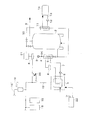
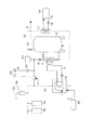
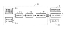
図1は、コージェネレーションシステムの第1実施例を示すシステム構成図であり、1は熱電併給装置を、2は蓄熱タンクをそれぞれ示している。
【0022】
蓄熱タンク2には、その底側から上部にわたって第1のポンプ3を備えた循環配管4が接続されている。循環配管4に熱交換器5が設けられ、熱電併給装置1と熱交換器5とにわたって、第2のポンプ6を備えた熱回収用循環配管7が接続されている。
【0023】
この構成により、蓄熱タンク2の下部から取り出した水を熱電併給装置1からの熱によって加熱し、その加熱された蓄熱水を蓄熱タンク2に戻して蓄熱するように構成されている。
循環配管4の熱交換器5よりも下流側の箇所に電熱変換手段としての電気ヒータ8が設けられ、熱電併給装置1で発生した電力が余剰の場合に、余剰電力を熱に変換して蓄熱タンク2の下部から取り出した水を加熱し、その加熱された蓄熱水を蓄熱タンク2に蓄えることができるように構成されている。図中9は、給湯用の給湯管を示している。
【0024】
循環配管4には、熱交換器5と直列になるように出力用循環配管10が接続されるとともに、その出力用循環配管10に暖房用熱交換器11が設けられ、暖房用熱交換器11に、第3のポンプ12を備えた暖房用循環配管13を介して、室内暖房機、床暖房機、浴室乾燥機などのセントラルヒーティング用の暖房装置14が接続されている。
【0025】
熱電併給装置1には、発電電力を取り出す電力線15が接続され、その電力線15に、照明装置や電気機器などの電気負荷16が接続されている。また、電力線15に逆潮流防止用の保護装置17を介して商用電源線18が接続され、発電電力で不足するときに商用電源からの電力を投入できるように買電手段19が構成されている。
【0026】
また、電力線15に、スイッチ回路20を介して電気ヒータ8が接続され、余剰電力の発生時に電気ヒータ8に通電するようになっている。この電気ヒータ8としては、二点鎖線で示すように、熱回収用循環配管7に設けるようにしても良い。図中21は補助加熱手段としてのガスボイラを示している。
【0027】
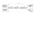
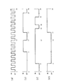
熱電併給装置1、スイッチ回路20およびガスボイラ21にはマイクロコンピュータ22が接続されている。
マイクロコンピュータ22には、図2のブロック図に示すように、需要変化特定手段23と運転状態入力手段24と演算手段25と比較手段26と運転制御手段27とが備えられている。
【0028】
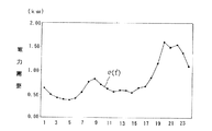
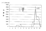
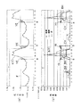
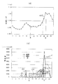
需要変化特定手段23では、図3および図4のグラフに示すように、1周期Tとしての1日間における、照明装置や電気機器駆動のための電力需要e(t’)、および、給湯や暖房などの熱需要h(t’)の経時的変化が、学習機能などによって予め記憶され、電力需要e(t’)および熱需要h(t’)の経時的変化を予め特定できるように構成されている。また、表−1に、上記給湯や暖房などの熱需要h(t’)の経時的変化の数値例を示す。なお、図3および図4は、多数の需要家の平均値をとって概略的な変化として示したものである。
【表1】
すなわち、前日の需要変化とか、1週間前の同じ曜日の需要変化などが順次記憶され、それらの需要変化に基づいて当日1日間および翌日1日間における熱需要h(t’)、および、電力需要e(t’)の経時的変化を、予め特定できるようになっているのである。
【0030】
運転状態入力手段24では、1周期Tとしての1日間を、例えば、30分間ごとなど、設定時間間隔dで分割し、各分割時間dそれぞれにおいて、熱電併給装置1を定格発電量で運転する状態と停止する状態それぞれを入力していくようになっている。
【0031】
演算手段25では、運転状態入力手段24から運転状態と停止状態とを後述する条件式や関係式に入力し、需要変化特定手段23からの当日1日間における熱需要h(t’)、および、電力需要e(t’)の経時的変化とに基づき、設定時間間隔dが30分であれば、2の48乗通りの組み合わせそれぞれにおける一次エネルギーの換算値を演算するようになっている。
【0032】
比較手段26では、演算手段25から入力される一次エネルギーの換算値を記憶し、その換算値と次に入力される換算値とを比較し、小さいほうの換算値とそのときの熱電併給装置1の運転状態と停止状態との組み合わせを新たに記憶していき、すべての組み合わせについて比較した後に、一次エネルギーの換算値が最小であった組み合わせを最適運転状態として出力するようになっている。
【0033】
運転制御手段27では、比較手段26からの最適運転状態の組み合わせに応答して、熱電併給装置1、スイッチ回路20およびガスボイラ21に駆動信号を出力し、一次エネルギーの換算値が最小になる状態でコージェネレーションシステムを運転するようになっている。
【0034】
次に、上記条件式について説明する。
第1実施例では、熱電併給装置1を発電効率が最も高い定格発電量(100%負荷) で運転し、電力需要e(t’)が定格発電量よりも小さい余剰電力分を電気ヒータ8によって熱に変換するものとする。ここでの定格発電量としては、1kwを例示する。この定格発電量は、例えば、0.8kwなど、使用する熱電併給装置1によって決まるものである。
【0035】
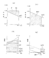
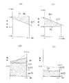
先ず、設定時間間隔dを30分(0.5時間)として、1周期Tにおける最初の1区間目の30分間(午前0時から午前0時30分)につき、熱電併給装置1を運転する状態と停止する状態それぞれにつき、図5の動作説明に供する参考図を用いて考察する。この図5は、前述した図3および図4とは関係が無く、説明上の参考にするために例示するものである。
【0036】
▲1▼運転状態
図5の(a)の電力需要と発電量との相関を示すグラフ、および、図5の(b)の熱需要と発生熱量との相関を示すグラフに示すように、余剰電力分YEを電気ヒータ8で熱に変換した熱量をH1 とすると、取得する熱量HT1 は、
HT1 =H1 +発生熱量CH+ガスボイラ21で補う熱量BH
となり、変換熱量H1 は、下記のように表される。
【数59】
e(t’)≧Fであれば、E1 (t’)=F
ここで、E1 (t’)は、負荷電力が定格発電量の電力F(1kw)を越える場合は定格電力量となり、負荷電力が定格電力より小さい場合はその負荷電力量となる電力量であり、e(t’)は、予め特定された電力需要(負荷電力)の経時的変化を示す関数である。
【0037】
また、発生熱量CH=0.5・F・k ……(35)
である。ここでkは熱電比である。
また、ガスボイラ21で補う熱量BHは、
【数60】
【0038】
一方、消費される熱量は、熱需要量に放熱量を加えたものになり、
【数61】
【0039】
これらのことから、1区間目の30分間経過後の蓄熱量S(0.5)が、
【数62】
【数63】
【0040】
ここでの一次エネルギーの換算値PEは、
PE=GI1 ・α+BI1 ・α’+BE1 ・β……(40)
となる。GI1 は、熱電併給装置1の運転に要する燃料供給量であり、下記(41)式で表され、また、αは燃料の一次エネルギーへの換算値である。また、BI1 は、ガスボイラ21の運転に要する燃料供給量であり、α’は燃料の一次エネルギーへの換算値である。熱電併給装置1およびガスボイラ21の燃料が同じであれば、α=α’となる。
【数64】
【0041】
BE1 は、1区間の時間(0.5時間)内での不足分の電力の投入量であり、次式(42)で表され、また、βは電力の一次エネルギーへの換算値である。但し、ここでは、電力不足では無いために、BE1 は零である。
【数65】
【数66】
【0042】
▲2▼運転停止状態
図5の(c)の電力需要と発電量との相関を示すグラフ、および、図5の(d)の熱需要と発生熱量との相関を示すグラフに示すように、熱電併給装置1が運転されないために、電気ヒータ8で変換する熱量、および、発生熱量のいずれも零である。したがって、1区間目の30分間経過後の蓄熱量S(0.5)は、初期蓄熱量S(0)から熱需要量と放熱量とを引いた分となる。熱量が不足したときにおいてのみ、図5の(d)に一点鎖線で示すように、取得熱量HT1 が、
HT1 =ガスボイラ21で補う熱量BH
となる。ガスボイラ21で補う熱量BHは、前述(36)式の通りである。条件式としては、前述運転状態のときと同様に(39)式となる。
【0043】
この場合の一次エネルギーの換算値PEは、GI1 ・αが零となり、
PE=BI1 ・α’+BE1 ・β……(44)
となる。
BI1 は、ガスボイラ21の運転に要する燃料供給量であり、α’は燃料の一次エネルギーへの換算値である。
BE1 は、1区間の時間(0.5時間)内での不足分の電力の投入量であり、熱電併給装置1の発電量が零であるために次式(45)で表され、また、βは電力の一次エネルギーへの換算値である。
【数67】
上述のようにして、運転状態と運転停止状態とを30分ごとの各区間で順次求めることになり、その条件式は下記(46)式で表される。
【数68】
【0045】
一次エネルギーの換算値PEは次の通りである。
PE=ΣPEn =ΣGIn ・α+ΣBIn ・α’+ΣBEn ・β……(47)
ここで、ΣPEn は、n=1〜48の一次エネルギーの総和である。GIn は熱電併給装置の運転に要する燃料供給量であり、次式(48)で表され、また、αは燃料の一次エネルギーへの換算値であり、ΣGIn ・αはn=1〜48の総和を求めている。また、BIn はガスボイラ21の運転に要する燃料供給量であり、α’は燃料の一次エネルギーへの換算値であり、ΣBIn ・α’はn=1〜48の総和を求めている。
【数69】
【0046】
ΣBEn は、1周期Tとなる所定時間T内での不足分の電力の投入量であり、次式(49)で表され、また、βは電力の一次エネルギーへの換算値であり、ΣBEn ・βはn=1〜48の総和を求めている。
【数70】
【数71】
【0047】
1周期としての1日間経過後において、その周期で取得した熱を翌日に消費することを許容するものであり、蓄熱タンク2内の蓄熱量の変動値S(t+n・d)は、最大蓄熱量Smax を越えない範囲のどのような値であっても良い。
【0048】
上述の結果、下記のような、運転停止状態と運転状態との様々な組み合わせが入力されて一次エネルギーの換算値PEが求められる。
▲1▼運転停止状態と運転状態とを30分ごとに交互に繰り返して運転する。[図6の(a)]
▲2▼午前0時〜午前9時、午前12時〜午後5時(12〜17時)、および、午後10時〜午後12時(22〜24時)それぞれを運転停止状態にし、午前9時〜午前12時、および、午後5時〜午後10時(17〜22時)それぞれを運転状態にして運転する。[図6の(b)]
▲3▼午前0時〜午前6時、午後3時〜午後6時(15〜18時)、および、午後8時〜午後12時(20〜24時)それぞれを運転停止状態にし、午前6時〜午後3時(6〜15時)、および、午後6時〜午後8時(18〜20時)それぞれを運転状態にして運転する。[図6の(c)]
▲3▼午前2時〜午後6時(2〜18時)を運転停止状態にし、午前0時〜午前2時、および、午後6時〜午後12時(18〜24時)それぞれを運転状態にして運転する。[図6の(d)]
【0049】
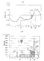
最終的に248通りの一次エネルギーの換算値PEが比較手段26に入力され、順次比較して一次エネルギーの換算値PEの小さい方が残され、一次エネルギーの換算値PEが最小となる運転状態と運転停止状態の組み合わせの最適運転状態が求められ、例えば、図7の(a)の電力需要と発電量との相関を示すグラフ、および、図7の(b)の熱需要と発生熱量との相関を示すグラフに示すように、運転制御手段27により、最適運転状態での運転が行われ、省エネルギー性を向上する最適な状態でコージェネレーションシステムを運転できることになる。図7において、aは運転開始時、bは運転終了時を示している。
【0050】
上記第1実施例では、1周期を1日(24時間)として30分間(0.5時間)の時間間隔で分割しているが、本発明としては、例えば、1日を10分間や20分間で分割するとか、また、生産ラインなどで、3日間とか1週間を1周期にするなど、その周期や分割時間間隔としては、適宜設定できる。
【0051】
そこで、1周期をT、分割時間間隔をdとして整理すると、以下のようになる。
蓄熱タンク2内の蓄熱量の変動値S(t+n・d)が常に下記条件式(1)を満たすとともに、下記一次エネルギーの換算値PE[式(4)]が最小となる組み合わせの最適運転状態を求め、求められた最適運転状態によって、熱電併給装置を定格発電量で運転するとともに電力需要が定格発電量の電力よりも小さいときの余剰電力を電気ヒータなどの電熱変換手段で熱に変換することになる。
【数72】
【0052】
HTn は分割時間間隔d内での取得熱量を示し、下記(2)式で表される。
【数73】
【数74】
e(t’)≧Fであれば、En (t’)=F
ここで、En (t’)は、負荷電力が定格発電量の電力を越える場合は定格電力量となり、負荷電力が定格電力より小さい場合はその負荷電力量となる電力量であり、e(t’)は、予め特定された電力需要(負荷電力)の経時的変化を示す関数である。
上記(2)式において、BO(t’)は、熱量不足を生じた際に、その不足分を補うように補助加熱手段を起動する場合の関数を示している。
【0053】
PE=ΣPEn =ΣGIn ・α+ΣBIn ・α’+ΣBEn ・β……(4)
ここで、ΣPEn は、n=1〜T/dの一次エネルギーの総和である。GIn は熱電併給装置の運転に要する燃料供給量であり、次式(5)で表され、また、αは燃料の一次エネルギーへの換算値であり、ΣGIn ・αはn=1〜T/dの総和を求めている。また、BIn は補助加熱手段の運転に要する燃料供給量であり、α’は燃料の一次エネルギーへの換算値であり、ΣBIn ・α’はn=1〜T/dの総和を求めている。
【数75】
【0054】
ΣBEn は、1周期Tとなる所定時間T内での不足分の電力の投入量であり、次式(6)で表され、また、βは電力の一次エネルギーへの換算値であり、n=1〜T/dの総和を求めている。
【数76】
【数77】
【0055】
次に、第2実施例について説明する。
この第2実施例では、電力需要e(t’)が定格発電量1kwよりも小さいところでは、電力需要e(t’)に合わせて発電し、定格発電量1kwよりも大きいところでは、定格発電量1kwで発電するように熱電併給装置1を運転するものである。
【0056】
また、この第2実施例では、前述第1実施例のような電気ヒータを用いないものであり、構成的には、図1および図2の電気ヒータ8およびスイッチ回路20を無くした構成となる。
【0057】
▲1▼運転状態
電力需要e(t’)が定格発電量1kwよりも小さいところでは、図8の(a)の電力需要と発電量との相関を示すグラフに示すように、電力需要e(t’)に合わせて発電する。図8の(b)の熱需要と発生熱量との相関を示すグラフに示すように、取得する熱量HT1 は、
HT1 =発生熱量CH+ガスボイラ21で補う熱量BH
となり、発生熱量CHは、下記のように表される。
【数78】
【0058】
また、ガスボイラ21で補う熱量BHは、
【数79】
【0059】
一方、消費される熱量は、熱需要量に放熱量を加えたものになり、
【数80】
【0060】
これらのことから、1区間目の30分間経過後の蓄熱量S(0.5)が、
【数81】
【数82】
【0061】
ここでの一次エネルギーの換算値PEは、
PE=GI1 ・α+BI1 ・α’+BE1 ・β……(56)
となる。GI1 は、熱電併給装置1の運転に要する燃料供給量であり、下記(57)式で表され、また、αは燃料の一次エネルギーへの換算値である。また、BI1 は、ガスボイラ21の運転に要する燃料供給量であり、α’は燃料の一次エネルギーへの換算値である。熱電併給装置1およびガスボイラ21の燃料が同じであれば、α=α’となる。
【数83】
【0062】
BE1 は、1区間の時間(0.5時間)内での不足分の電力の投入量であり、次式(58)で表され、また、βは電力の一次エネルギーへの換算値である。但し、ここでは零である。
【数84】
【数85】
【0063】
定格発電量1kwよりも大きいところでは、図8の(c)の電力需要と発電量との相関を示すグラフに示すように、定格発電量Fで発電する。図8の(d)の熱需要と発生熱量との相関を示すグラフに示すように、取得する熱量HTn は、
HTn =発生熱量CH+ガスボイラ21で補う熱量BH
となり、発生熱量CHは、下記のように表される。
CH=0.5・F・k ……(60)
ここで、kは熱電比である。
【0064】
また、ガスボイラ21で補う熱量BHは、
【数86】
【0065】
一方、消費される熱量は、熱需要量に放熱量を加えたものになり、
【数87】
【0066】
これらのことから、n区間目の30分間経過後の蓄熱量S(0.5n)が、
【数88】
【数89】
【0067】
ここでの一次エネルギーの換算値PEは、
PE=GIn ・α+BIn ・α’+BEn ・β……(65)
となる。GIn は、熱電併給装置1の運転に要する燃料供給量であり、下記(66)式で表され、また、αは燃料の一次エネルギーへの換算値である。また、BIn は、ガスボイラ21の運転に要する燃料供給量であり、α’は燃料の一次エネルギーへの換算値である。熱電併給装置1およびガスボイラ21の燃料が同じであれば、α=α’となる。
【数90】
【0068】
BEn は、1区間の時間(0.5時間)内での不足分の電力の投入量であり、次式(67)で表され、また、βは電力の一次エネルギーへの換算値である。
【数91】
【数92】
【0069】
▲2▼運転停止状態
前述第1実施例において電気ヒータ8で変換する熱量が零であるため、電気ヒータ8を設けない場合と同じであり、この第2実施例の作用も、図5の(c)および(d)によって説明した第1実施例における運転停止状態と同じであり、説明は省略する。
【0070】
この第2実施例によれば、最終的に248通りの一次エネルギーの換算値PEが比較手段26に入力され、順次比較して一次エネルギーの換算値PEの小さい方が残され、一次エネルギーの換算値PEが最小となる運転状態と運転停止状態の組み合わせの最適運転状態が求められ、例えば、図9の(a)の電力需要と発電量との相関を示すグラフ、および、図9の(b)の熱需要と発生熱量との相関を示すグラフに示すように、運転制御手段27により、最適運転状態での運転が行われ、省エネルギー性を向上する最適な状態でコージェネレーションシステムを運転できることになる。図9において、aは運転開始時、bは運転終了時を示している。
【0071】
以上のことから、1周期をT、分割時間間隔をdとして整理すると、以下のようになる。
蓄熱タンク2内の蓄熱量の変動値S(t+n・d)が常に下記条件式(8)を満たすとともに、下記一次エネルギーの換算値PE[式(10)]が最小となる組み合わせの最適運転状態を求め、求められた最適運転状態によって、熱電併給装置を定格発電量で運転するとともに電力需要が定格発電量の電力よりも小さいときには電力需要の変化に追従させて運転することとなる。
【数93】
【0072】
HTn は分割時間間隔d内での取得熱量を示し、下記(9)式で表される。
【数94】
また、BO(t’)は、熱量不足を生じた際に、その不足分を補うように補助加熱手段を起動する場合の関数を示している。
【0073】
PE=ΣPEn =ΣGIn ・α+ΣBIn ・α’+ΣBEn ・β……(10)
ここで、ΣPEn は、n=1〜T/dの一次エネルギーの総和である。GIn は熱電併給装置の運転に要する燃料供給量であり、次式(5a)で表され、また、αは燃料の一次エネルギーへの換算値であり、ΣGIn ・αはn=1〜T/dの総和を求めている。また、BIn は補助加熱手段の運転に要する燃料供給量であり、α’は燃料の一次エネルギーへの換算値であり、ΣBIn ・α’はn=1〜T/dの総和を求めている。
【数95】
【0074】
ΣBEn は、1周期Tとなる所定時間T内での不足分の電力の投入量であり、次式(10)で表され、また、βは電力の一次エネルギーへの換算値であり、n=1〜T/dの総和を求めている。
【数96】
【数97】
【0075】
次に、第3実施例について説明する。
この第3実施例では、熱電併給装置1を500wと定格発電量1kwとの2段に設定した発電量で運転するものとする。すなわち、この第3実施例では、設定時間間隔dを30分(0.5時間)として、1周期Tにおける最初の1区間目の30分間(午前0時から午前0時30分)につき、熱電併給装置1を定格発電量1kwで運転する状態、500wで運転する状態、および、運転を停止する状態それぞれにつき、図8の動作説明に供する参考図を用いて考察する。
また、この第3実施例では、第1実施例と同様に電熱変換手段としての電気ヒータ8を備え、発電電力が電力需要を越えた余剰電力分は熱に変換するようにしている。
【0076】
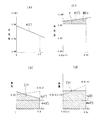
▲1▼定格発電量1kwでの運転状態
図10の(a)の電力需要と発電量との相関を示すグラフ、および、図10の(b)の熱需要と発生熱量との相関を示すグラフに示すように、余剰電力分YEを電気ヒータ8で熱に変換した熱量をH1 とすると、取得する熱量HT1 は、
HT1 =H1 +発生熱量CH+ガスボイラ21で補う熱量BH
となり、変換熱量H1 は、下記のように表される。
【数98】
e(t’)≧F1 であれば、E1 (t’)=F1
ここで、E1 (t’)は、負荷電力が定格発電量の電力F1 (1kw)を越える場合は定格電力量となり、負荷電力が定格電力より小さい場合はその負荷電力量となる電力量であり、e(t’)は、予め特定された電力需要(負荷電力)の経時的変化を示す関数である。
【0077】
また、発生熱量CH=0.5・F1 ・k1 ……(70)
である。ここでk1 は、定格発電量F1 (1kw)での運転した時の熱電比である。
また、ガスボイラ21で補う熱量BHは、
【数99】
【0078】
一方、消費される熱量は、熱需要量に放熱量を加えたものになり、
【数100】
【0079】
これらのことから、1区間目の30分間経過後の蓄熱量S(0.5)が、
【数101】
【数102】
【0080】
ここでの一次エネルギーの換算値PEは、
PE=GI1 ・α+BI1 ・α’+BE1 ・β……(75)
となる。GI1 は、熱電併給装置1の運転に要する燃料供給量であり、下記(76)式で表され、また、αは燃料の一次エネルギーへの換算値である。また、BI1 は、ガスボイラ21の運転に要する燃料供給量であり、α’は燃料の一次エネルギーへの換算値である。熱電併給装置1およびガスボイラ21の燃料が同じであれば、α=α’となる。
【数103】
【0081】
BE1 は、1区間の時間(0.5時間)内での不足分の電力の投入量であり、次式(77)で表され、また、βは電力の一次エネルギーへの換算値である。但し、ここでは零である。
【数104】
【数105】
【0082】
▲2▼発電量500wでの運転状態
図10の(c)の電力需要と発電量との相関を示すグラフ、および、図10の(d)の熱需要と発生熱量との相関を示すグラフに示すように、発電電力F2 が電力需要e(t’)よりも小さくて余剰電力分が無いために、変換熱量H1 が零であり、取得する熱量HT1 は、
HT1 =発生熱量CH+ガスボイラ21で補う熱量BH
となる。
【0083】
また、発生熱量CH=0.5・F2 ・k2 ……(79)
である。ここでk2 は、発電量F2 (500kw)での運転した時の熱電比である。
また、ガスボイラ21で補う熱量BHは、
【数106】
【0084】
一方、消費される熱量は、熱需要量に放熱量を加えたものになり、
【数107】
【0085】
これらのことから、1区間目の30分間経過後の蓄熱量S(0.5)が、
【数108】
【数109】
【0086】
ここでの一次エネルギーの換算値PEは、
PE=GI1 ・α+BI1 ・α’+BE1 ・β……(84)
となる。GI1 は、熱電併給装置1の運転に要する燃料供給量であり、下記(85)式で表され、また、αは燃料の一次エネルギーへの換算値である。また、BI1 は、ガスボイラ21の運転に要する燃料供給量であり、α’は燃料の一次エネルギーへの換算値である。熱電併給装置1およびガスボイラ21の燃料が同じであれば、α=α’となる。
【数110】
【0087】
BE1 は、1区間の時間(0.5時間)内での不足分の電力の投入量であり、次式(86)で表され、また、βは電力の一次エネルギーへの換算値である。
【数111】
【数112】
【0088】
▲3▼運転停止状態
この第3実施例の作用は、図5の(c)および(d)によって説明した第1実施例における運転停止状態と同じであり、説明は省略する。
【0089】
この第3実施例の場合、最終的に348通りの一次エネルギーの換算値PEが比較手段26に入力され、順次比較して一次エネルギーの換算値PEの小さい方が残され、一次エネルギーの換算値PEが最小となる、発電量500wおよび1kwそれぞれの運転状態と運転停止状態の組み合わせの最適運転状態が求められ、例えば、図11の(a)の電力需要と発電量との相関を示すグラフ、および、図11の(b)の熱需要と発生熱量との相関を示すグラフに示すように、運転制御手段27により、最適運転状態での運転が行われ、省エネルギー性を向上する最適な状態でコージェネレーションシステムを運転できることになる。図11において、a1は発電量500wでの運転開始時、a2は発電量500wでの運転終了時でかつ発電量1kwでの運転開始時、a3は発電量1kwでの運転終了時を示している。
【0090】
1周期としての1日間経過後において、その周期で取得した熱を翌日に消費することを許容するものであり、蓄熱タンク2内の蓄熱量の変動値S(t+n・d)は、最大蓄熱量Smax を越えない範囲のどのような値であっても良い。
また、上記第3実施例では、500w運転および定格発電量1kw運転の2種類のステップ運転を行うようにしているが、本発明としては、例えば、700w運転および定格発電量1kw運転の2段に設定した発電量の運転を行うとか、500w運転、700w運転および定格発電量1kw運転などの3段以上に設定した発電量の運転を行うようにしても良く、要するに複数段の設定発電量で運転する場合を含むものである。
【0091】
以上のことから、1周期をT、分割時間間隔をdとして整理すると、以下のようになる。
蓄熱タンク2内の蓄熱量の変動値S(t+n・d)が常に下記条件式(13)を満たすとともに、下記一次エネルギーの換算値PE[式(16)]が最小となる組み合わせの最適運転状態を求め、求められた最適運転状態によって、熱電併給装置1を複数段の設定発電量で運転するとともに電力需要が設定発電量の電力よりも小さいときの余剰電力を電気ヒータなどの電熱変換手段で熱に変換することになる。
【数113】
【0092】
HTn は分割時間間隔d内での取得熱量を示し、下記(14)式で表される。
【数114】
【数115】
e(t’)≧Fm であれば、En (t’)=Fm
ここで、En (t’)は、負荷電力が設定発電量Fm を越える場合は設定電力量となり、負荷電力が設定発電量Fm より小さい場合はその負荷電力量となる電力量であり、e(t’)は、予め特定された電力需要(負荷電力)の経時的変化を示す関数である。
上記(14)式において、BO(t’)は、熱量不足を生じた際に、その不足分を補うように補助加熱手段を起動する場合の関数を示している。
【0093】
PE=ΣPEn =ΣGIn ・α+ΣBIn ・α’+ΣBEn ・β……(16)
ここで、ΣPEn は、n=1〜T/dの一次エネルギーの総和である。GIn は熱電併給装置の運転に要する燃料供給量であり、次式(17)で表され、また、αは燃料の一次エネルギーへの換算値であり、ΣGIn ・αはn=1〜T/dの総和を求めている。また、BIn は補助加熱手段の運転に要する燃料供給量であり、α’は燃料の一次エネルギーへの換算値であり、ΣBIn ・α’はn=1〜T/dの総和を求めている。
【数116】
【0094】
ΣBEn は、1周期Tとなる所定時間T内での不足分の電力の投入量であり、次式(18)で表され、また、βは電力の一次エネルギーへの換算値であり、n=1〜T/dの総和を求めている。
【数117】
【数118】
【0095】
図12は、コージェネレーションシステムの第4実施例を示すシステム構成図であり、第1実施例と異なるところは次の通りである。
すなわち、電気ヒータ8を無くし、電力線15に、スイッチ回路31を介して電力供給線32が接続され、余剰電力の発生時に、その余剰電力分を第3者に売るように売電手段33が構成されている。
電力供給線32には電力計34が介装され、第3者に売った電力量を計測するように構成されている。他の構成は第1実施例と同じであり、同一図番を付すことによりその説明は省略する。
【0096】
図13の第4実施例のブロック図に示すように、熱電併給装置1、スイッチ回路31およびガスボイラ21にはマイクロコンピュータ35が接続されている。
マイクロコンピュータ35には、前述第1実施例と同様に、需要変化特定手段23と運転状態入力手段24と演算手段25と比較手段26と運転制御手段27とが備えられている。
【0097】
この第4実施例では、電気ヒータ8で熱に変換しない分だけ取得熱量が減少し、かつ、第3者に売った余剰電力分を一次エネルギーに換算した分だけ一次エネルギーの換算値が減少することになり、次に説明する。
【0098】
▲1▼運転状態
取得する熱量HT1 は、
HT1 =発生熱量CH+ガスボイラ21で補う熱量BH
となる。
【0099】
また、発生熱量CH=0.5・F・k ……(88)
である。ここでkは熱電比である。
また、ガスボイラ21で補う熱量BHは、
【数119】
【0100】
一方、消費される熱量は、熱需要量に放熱量を加えたものになり、
【数120】
【0101】
これらのことから、1区間目の30分間経過後の蓄熱量S(0.5)が、
【数121】
【数122】
【0102】
ここでの一次エネルギーの換算値PEは、
PE=GI1 ・α+BI1 ・α’+BE1 ・β−SE1 ・γ……(93)
となる。GI1 は、熱電併給装置1の運転に要する燃料供給量であり、下記(94)式で表され、また、αは燃料の一次エネルギーへの換算値である。また、BI1 は、ガスボイラ21の運転に要する燃料供給量であり、α’は燃料の一次エネルギーへの換算値である。熱電併給装置1およびガスボイラ21の燃料が同じであれば、α=α’となる。
【数123】
【0103】
BE1 は、1区間の時間(0.5時間)内での不足分の電力の投入量であり、次式(95)で表され、また、βは電力の一次エネルギーへの換算値である。但し、ここでは、電力不足では無いために、BE1 は零である。
【数124】
【数125】
【0104】
また、SE1 は、売電手段で第3者に売る余剰電力量[図5の(a)の余剰電力分YEに相当]で、F>E1 (t’)の分を積算するものであり、下記(97)式で表され、また、γは第3者に売るときの価格分を一次エネルギーに換算した換算値である。
【数126】
e(t’)≧Fであれば、E1 (t’)=F
ここで、E1 (t’)は、負荷電力が定格発電量の電力を越える場合は定格電力量となり、負荷電力が定格電力より小さい場合はその負荷電力量となる電力量であり、e(t’)は、予め特定された電力需要(負荷電力)の経時的変化を示す関数である。
【0105】
▲2▼運転停止状態
熱電併給装置1が運転されないために、余剰電力が発生せず、第1実施例で説明した場合と同じである。すなわち、取得熱量HT1 が、
HT1 =ガスボイラ21で補う熱量BH
となり、ガスボイラ21で補う熱量BHは、前述(89)式の通りである。条件式としては、前述運転状態のときと同様に(92)式となる。
【0106】
この場合の一次エネルギーの換算値PEは、GI1 ・αおよびSE1 ・γが零となり、
PE=BI1 ・α’+BE1 ・β……(98)
となる。
BI1 は、ガスボイラ21の運転に要する燃料供給量であり、α’は燃料の一次エネルギーへの換算値である。
BE1 は、1区間の時間(0.5時間)内での不足分の電力の投入量であり、熱電併給装置1の発電量が零であるために次式(99)で表され、また、βは電力の一次エネルギーへの換算値である。
【数127】
上述のようにして、運転状態と運転停止状態とを30分ごとの各区間で順次求めることになり、その条件式は下記(100)式で表される。
【数128】
【0108】
一次エネルギーの換算値PEは次の通りである。
【数129】
【0109】
ΣBEn は、1周期Tとなる所定時間T内での不足分の電力の投入量であり、次式(103)で表され、また、βは電力の一次エネルギーへの換算値であり、ΣBEn ・βはn=1〜48の総和を求めている。
【数130】
【数131】
【0110】
また、ΣSEn は売電手段で第3者に売る余剰電力量で、F>En (t’)の分を積算するものであり、下記(105)式で表され、また、γは第3者に売るときの価格分を一次エネルギーに換算した換算値であり、n=1〜48の総和を求めている。
【数132】
e(t’)≧Fであれば、En (t’)=F
ここで、En (t’)は、負荷電力が定格発電量の電力を越える場合は定格電力量となり、負荷電力が定格電力より小さい場合はその負荷電力量となる電力量であり、e(t’)は、予め特定された電力需要(負荷電力)の経時的変化を示す関数である。
【0111】
1周期としての1日間経過後において、その周期で取得した熱を翌日に消費することを許容するものであり、蓄熱タンク2内の蓄熱量の変動値S(t+n・d)は、最大蓄熱量Smax を越えない範囲のどのような値であっても良い。
【0112】
上述の結果、第1実施例と同様に、運転停止状態と運転状態との様々な組み合わせが入力されて一次エネルギーの換算値PEが求められる。
【0113】
最終的に248通りの一次エネルギーの換算値PEが比較手段26に入力され、順次比較して一次エネルギーの換算値PEの小さい方が残され、一次エネルギーの換算値PEが最小となる運転状態と運転停止状態の組み合わせの最適運転状態が求められ、運転制御手段27により、最適運転状態での運転が行われ、省エネルギー性を向上する最適な状態でコージェネレーションシステムを運転できることになる。
【0114】
この第4実施例において、1周期をT、分割時間間隔をdとして整理すると、以下のようになる。
蓄熱タンク2内の蓄熱量の変動値S(t+n・d)が常に下記条件式(20)を満たすとともに、下記一次エネルギーの換算値PE[式(22)]が最小となる組み合わせの最適運転状態を求め、求められた最適運転状態によって、熱電併給装置を定格発電量で運転するとともに電力需要が定格発電量の電力よりも小さいときの余剰電力を売電手段33で第3者に売ることになる。
【数133】
HTn は分割時間間隔d内での取得熱量を示し、下記(21)式で表される。
【数134】
上記(21)式において、BO(t’)は、熱量不足を生じた際に、その不足分を補うように補助加熱手段を起動する場合の関数を示している。
【数135】
ΣBEn は、1周期Tとなる所定時間T内での不足分の電力の投入量であり、次式(24)で表され、また、βは電力の一次エネルギーへの換算値であり、n=1〜T/dの総和を求めている。
【数136】
【数137】
【数138】
e(t’)≧Fであれば、En (t’)=F
ここで、En (t’)は、負荷電力が定格発電量の電力を越える場合は定格電力量となり、負荷電力が定格電力より小さい場合はその負荷電力量となる電力量であり、e(t’)は、予め特定された電力需要(負荷電力)の経時的変化を示す関数である。
【0115】
次に、第5実施例について説明する。
この第5実施例では、第3実施例と同様に、熱電併給装置1を500wと定格発電量1kwとの2段に設定した発電量で運転するものとする。また、この第5実施例では、第4実施例と同様に売電手段33を備え、発電電力が電力需要を越えた余剰電力分は第3者に売るようにしている。
【0116】
▲1▼定格発電量1kwでの運転状態
取得する熱量HT1 は、
HT1 =H1 +発生熱量CH+ガスボイラ21で補う熱量BH
となる。
【0117】
また、発生熱量CH=0.5・F1 ・k1 ……(106)
である。ここでk1 は、定格発電量F1 (1kw)での運転した時の熱電比である。
また、ガスボイラ21で補う熱量BHは、
【数139】
【0118】
一方、消費される熱量は、熱需要量に放熱量を加えたものになり、
【数140】
【0119】
これらのことから、1区間目の30分間経過後の蓄熱量S(0.5)が、
【数141】
【数142】
【0120】
ここでの一次エネルギーの換算値PEは、
PE=GI1 ・α+BI1 ・α’+BE1 ・β−SE1 ・γ……(111)
となる。GI1 は、熱電併給装置1の運転に要する燃料供給量であり、下記(112)式で表され、また、αは燃料の一次エネルギーへの換算値である。また、BI1 は、ガスボイラ21の運転に要する燃料供給量であり、α’は燃料の一次エネルギーへの換算値である。熱電併給装置1およびガスボイラ21の燃料が同じであれば、α=α’となる。
【数143】
【0121】
BE1 は、1区間の時間(0.5時間)内での不足分の電力の投入量であり、次式(113)で表され、また、βは電力の一次エネルギーへの換算値である。
但し、ここでは零である。
【数144】
【数145】
【0122】
また、SE1 は、売電手段で第3者に売る余剰電力量[図10の(a)の余剰電力分YEに相当]で、F1 >E1 (t’)の分を積算するものであり、下記(115)式で表され、また、γは第3者に売るときの価格分を一次エネルギーに換算した換算値である。
【数146】
e(t’)≧F1 であれば、E1 (t’)=F1
ここで、E1 (t’)は、負荷電力が定格発電量の電力を越える場合は定格電力量となり、負荷電力が定格電力より小さい場合はその負荷電力量となる電力量であり、e(t’)は、予め特定された電力需要(負荷電力)の経時的変化を示す関数である。
【0123】
▲2▼発電量500wでの運転状態
図10の(c)の電力需要と発電量との相関を示すグラフ、および、図10の(d)の熱需要と発生熱量との相関を示すグラフに示すように、発電電力F2 が電力需要e(t’)よりも小さくて余剰電力分が無いために、変換熱量H1 が零であり、取得する熱量HT1 は、
HT1 =発生熱量CH+ガスボイラ21で補う熱量BH
となる。
【0124】
また、発生熱量CH=0.5・F2 ・k2 ……(116)
である。ここでk2 は、発電量F2 (500kw)での運転した時の熱電比である。
また、ガスボイラ21で補う熱量BHは、
【数147】
【0125】
一方、消費される熱量は、熱需要量に放熱量を加えたものになり、
【数148】
【0126】
これらのことから、1区間目の30分間経過後の蓄熱量S(0.5)が、
【数149】
【数150】
【0127】
ここでの一次エネルギーの換算値PEは、
PE=GI1 ・α+BI1 ・α’+BE1 ・β……(121)
となる。GI1 は、熱電併給装置1の運転に要する燃料供給量であり、下記(122)式で表され、また、αは燃料の一次エネルギーへの換算値である。また、BI1 は、ガスボイラ21の運転に要する燃料供給量であり、α’は燃料の一次エネルギーへの換算値である。熱電併給装置1およびガスボイラ21の燃料が同じであれば、α=α’となる。
【数151】
【0128】
BE1 は、1区間の時間(0.5時間)内での不足分の電力の投入量であり、次式(123)で表され、また、βは電力の一次エネルギーへの換算値である。
【数152】
【数153】
【0129】
▲3▼運転停止状態
この第5実施例の作用は、図5の(c)および(d)によって説明した第1実施例における運転停止状態と同じであり、説明は省略する。
【0130】
この第5実施例の場合、最終的に348通りの一次エネルギーの換算値PEが比較手段26に入力され、順次比較して一次エネルギーの換算値PEの小さい方が残され、一次エネルギーの換算値PEが最小となる、発電量500wおよび1kwそれぞれの運転状態と運転停止状態の組み合わせの最適運転状態が求められ、運転制御手段27により、最適運転状態での運転が行われ、省エネルギー性を向上する最適な状態でコージェネレーションシステムを運転できることになる。
【0131】
1周期としての1日間経過後において、その周期で取得した熱を翌日に消費することを許容するものであり、蓄熱タンク2内の蓄熱量の変動値S(t+n・d)は、最大蓄熱量Smax を越えない範囲のどのような値であっても良い。
また、上記第3実施例では、500w運転および定格発電量1kw運転の2種類のステップ運転を行うようにしているが、本発明としては、例えば、700w運転および定格発電量1kw運転の2段に設定した発電量の運転を行うとか、500w運転、700w運転および定格発電量1kw運転などの3段以上に設定した発電量の運転を行うようにしても良く、要するに複数段の設定発電量で運転する場合を含むものである。
【0132】
以上のことから、1周期をT、分割時間間隔をdとして整理すると、以下のようになる。
蓄熱タンク2内の蓄熱量の変動値S(t+n・d)が常に下記条件式(27)を満たすとともに、下記一次エネルギーの換算値PE[式(29)]が最小となる組み合わせの最適運転状態を求め、求められた最適運転状態によって、熱電併給装置1を複数段の設定発電量で運転するとともに電力需要が設定発電量の電力よりも小さいときの余剰電力を電気ヒータなどの電熱変換手段で熱に変換することになる。
【数154】
【0133】
HTn は分割時間間隔d内での取得熱量を示し、下記(28)式で表される。
【数155】
上記(28)式において、BO(t’)は、熱量不足を生じた際に、その不足分を補うように補助加熱手段を起動する場合の関数を示している。
【数156】
ΣBEn は、1周期Tとなる所定時間T内での不足分の電力の投入量であり、次式(31)で表され、また、βは電力の一次エネルギーへの換算値であり、n=1〜T/dの総和を求めている。
【数157】
【数158】
【数159】
e(t’)≧Fm であれば、En (t’)=F
ここで、En (t’)は、負荷電力が設定発電量Fm を越える場合は設定電力量となり、負荷電力が設定発電量Fm より小さい場合はその負荷電力量となる電力量であり、e(t’)は、予め特定された電力需要(負荷電力)の経時的変化を示す関数である。
【0134】
図14は、第6実施例のブロック図であり、第1実施例と異なるところは次の通りである。
すなわち、マイクロコンピュータ22に熱電併給装置1の1周期内における発停回数が設定する発停回数設定手段41が接続され、この発停回数設定手段41で設定した発停回数を演算手段25に入力するようになっている。
【0135】
演算手段25では、運転状態入力手段24から入力される運転状態の発停回数が、発停回数設定手段41から入力される設定発停回数を越えたときに、一次エネルギーの換算値の演算を停止して、次の運転状態の入力に移行するようになっている。
【0136】
この第6実施例によれば、熱電併給装置1の1周期内における発停回数が設定回数以下で一次エネルギーの換算値PEが最小となる組み合わせの最適運転状態を求めることができ、熱電併給装置1の耐久性を向上できる。
発停回数としては、熱電併給装置1の特性や希望する耐用年数などによって適宜所望の回数を設定すれば良い。例えば、希望する耐用年数が10年であれば3回程度に、そして、スタータ等の交換を考慮すれば6回程度に設定する、といった具合である。なお、この構成は、第2、第3、第4および第5実施例にも同様に適用できる。
【0137】
上記第1、第2、第3、第4、第5および第6実施例それぞれにおけるシステムからの放熱量ex(t’)は、蓄熱タンク2、配管および熱電併給装置1の筐体からの放熱量ST(t),PL(t),GE(t)を含み、いずれも、主としてシステム構築時の規模に比例した熱容量によって決まるものである。例えば、配管や熱電併給装置1の筐体や蓄熱タンク2を断熱材で覆うような構成を採用すれば、その放熱量を抑えることができるが、断熱材の断熱効果もシステム構築時に予め特定できるものであり、いずれにしても、配管や熱電併給装置1の筐体や蓄熱タンク2からの放熱量は、実験や計算や学習効果などによって予め特定できるものである。
【0138】
また、初期蓄熱量S(0)は、予め特定される電力需要と熱需要とに基づいて適宜設定されるものであり、予め特定できるものである。表−1に基づけば、初期蓄熱量は2,000[×(1/860)kW]である。
【0139】
本発明は、家庭用や製造工場や商用ビルなどの各種の用途のコージェネレーションシステムに適用できる。
【0140】
【発明の効果】
以上の説明から明らかなように、請求項1および請求項2に係る発明のコージェネレーションシステムの運転方法によれば、電力需要が定格発電量よりも小さいときの電力需要を越える余剰の電力を電熱変換手段によって熱に変換し、熱電併給装置を定格発電量で運転して発電するから、定格発電量よりも小さい発電量で運転する場合に比べて見掛け上の発電効率を高くできる。
しかも、例えば、1日などの1周期内にとどまらず、翌日の午前分の熱需要など次の1周期内の熱需要の一部を賄うために消費することを許容し、蓄熱タンクに貯めた熱が消費までの間に放熱する分と、不足分の電力を買電手段で賄うことと、変換した熱や熱電併給装置で発生した熱や蓄熱タンクに貯めた熱量で熱需要を賄うのに不足するときに不足分の熱を補助加熱手段で補うことをも考慮して、全体の一次エネルギーへの変換値が最小となるように運転するから、蓄熱タンクの容量の制約に起因してわずかな熱量不足を生じても、補助加熱手段の利用により良好に対処でき、放熱ロスのより少ない状態を選択して熱電併給装置を運転でき、省エネルギー性を良好に向上できる。
【0141】
また、請求項3および請求項4に係る発明のコージェネレーションシステムの運転方法によれば、電力需要が定格発電量を越えるときは熱電併給装置を定格発電量で運転して発電するから発電効率を高くでき、また、電力需要が定格発電量よりも小さいときは熱電併給装置を電力需要に追従して運転して発電し、余剰電力を発生させないようにするから、常時定格発電量で運転するよりも効率を向上できるとともに熱に変換するための構成を不用にできる。
しかも、例えば、1日などの1周期内にとどまらず、翌日の午前分の熱需要など次の1周期内の熱需要の一部を賄うために消費することを許容し、蓄熱タンクに貯めた熱が消費までの間に放熱する分と、不足分の電力を買電手段で賄うことと、変換した熱や熱電併給装置で発生した熱や蓄熱タンクに貯めた熱量で熱需要を賄うのに不足するときに不足分の熱を補助加熱手段で補うことをも考慮して、全体の一次エネルギーへの変換値が最小となるように運転するから、蓄熱タンクの容量の制約に起因してわずかな熱量不足を生じても、補助加熱手段の利用により良好に対処でき、放熱ロスのより少ない状態を選択して熱電併給装置を運転でき、省エネルギー性を良好に向上できる。
【0142】
また、請求項5および請求項6に係る発明のコージェネレーションシステムの運転方法によれば、熱電併給装置を複数段に設定した発電量で運転するから、常時一定出力で運転するよりも余剰電力が少なく効率良い運転ができる。
しかも、例えば、1日などの1周期内にとどまらず、翌日の午前分の熱需要など次の1周期内の熱需要の一部を賄うために消費することを許容し、蓄熱タンクに貯めた熱が消費までの間に放熱する分と、不足分の電力を買電手段で賄うことと、変換した熱や熱電併給装置で発生した熱や蓄熱タンクに貯めた熱量で熱需要を賄うのに不足するときに不足分の熱を補助加熱手段で補うことをも考慮して、全体の一次エネルギーへの変換値が最小となるように運転するから、蓄熱タンクの容量の制約に起因してわずかな熱量不足を生じても、補助加熱手段の利用により良好に対処でき、放熱ロスのより少ない状態を選択して熱電併給装置を運転でき、省エネルギー性を良好に向上できる。
【0143】
また、請求項7および請求項8に係る発明のコージェネレーションシステムの運転方法によれば、電力需要が定格発電量よりも小さいときの電力需要を越える余剰の電力を売電手段によって第3者に売り、熱電併給装置を定格発電量で運転して発電するから、定格発電量よりも小さい発電量で運転する場合に比べて見掛け上の発電効率を高くできる。
しかも、例えば、1日などの1周期内にとどまらず、翌日の午前分の熱需要など次の1周期内の熱需要の一部を賄うために消費することを許容し、蓄熱タンクに貯めた熱が消費までの間に放熱する分と、不足分の電力を買電手段で賄うことと、余剰の電力を売電手段によって第3者に売ること、ならびに、熱電併給装置で発生した熱や蓄熱タンクに貯めた熱量で熱需要を賄うのに不足するときに不足分の熱を補助加熱手段で補うことをも考慮して、全体の一次エネルギーへの変換値が最小となるように運転するから、蓄熱タンクの容量の制約に起因してわずかな熱量不足を生じても、補助加熱手段の利用により良好に対処でき、放熱ロスのより少ない状態を選択して熱電併給装置を運転でき、省エネルギー性を良好に向上できる。
【0144】
また、請求項9および請求項10に係る発明のコージェネレーションシステムの運転方法によれば、熱電併給装置を複数段に設定した発電量で運転するから、常時一定出力で運転するよりも余剰電力が少なく効率良い運転ができる。
しかも、例えば、1日などの1周期内にとどまらず、翌日の午前分の熱需要など次の1周期内の熱需要の一部を賄うために消費することを許容し、蓄熱タンクに貯めた熱が消費までの間に放熱する分と、不足分の電力を買電手段で賄うことと、余剰の電力を売電手段によって第3者に売ること、ならびに、熱電併給装置で発生した熱や蓄熱タンクに貯めた熱量で熱需要を賄うのに不足するときに不足分の熱を補助加熱手段で補うことをも考慮して、全体の一次エネルギーへの変換値が最小となるように運転するから、蓄熱タンクの容量の制約に起因してわずかな熱量不足を生じても、補助加熱手段の利用により良好に対処でき、放熱ロスのより少ない状態を選択して熱電併給装置を運転でき、省エネルギー性を良好に向上できる。
【0145】
また、請求項11に係る発明のコージェネレーションシステムの運転方法によれば、使用する熱電併給装置個々の特性や希望する耐用年数などに応じて、その発停回数を設定し、必要以上の発停の繰り返しを回避し、熱電併給装置の寿命が早期に低下することを防止して耐久性を向上できる。
【図面の簡単な説明】
【図1】本発明の第1実施例に係るコージェネレーションシステムを示すシステム構成図である。
【図2】ブロック図である。
【図3】実施例の説明に供する電力需要の経時的変化を示すグラフである。
【図4】実施例の説明に供する熱需要の経時的変化を示すグラフである。
【図5】第1実施例の動作説明に供する参考図であり、(a)および(c)は、それぞれ電力需要と発電量との相関を示し、(b)および(d)は、それぞれ熱需要と発生熱量との相関を示している。
【図6】(a)、(b)、(c)および(d)は、それぞれ運転停止状態と運転状態との組み合わせ例を示すタイムチャートである。
【図7】第1実施例の最適運転状態を例示するグラフであり、(a)は電力需要と発電量との相関を示し、(b)は熱需要と発生熱量との相関を示している。
【図8】第2実施例の動作説明に供する参考図であり、(a)および(c)は、それぞれ電力需要と発電量との相関を示し、(b)および(d)は、それぞれ熱需要と発生熱量との相関を示している。
【図9】第2実施例の最適運転状態を例示するグラフであり、(a)は電力需要と発電量との相関を示し、(b)は熱需要と発生熱量との相関を示している。
【図10】第3実施例の動作説明に供する参考図であり、(a)および(c)は、それぞれ電力需要と発電量との相関を示し、(b)および(d)は、それぞれ熱需要と発生熱量との相関を示している。
【図11】第3実施例の最適運転状態を例示するグラフであり、(a)は電力需要と発電量との相関を示し、(b)は熱需要と発生熱量との相関を示している。
【図12】本発明の第4実施例に係るコージェネレーションシステムを示すシステム構成図である。
【図13】第4実施例のブロック図である。
【図14】第6実施例のブロック図である。
【符号の説明】
1…熱電併給装置
2…蓄熱タンク
8…電熱変換手段としての電気ヒータ
19…買電手段
21…補助加熱手段としてのガスボイラ
23…需要変化特定手段
33…売電手段
41…発停回数設定手段[0001]
BACKGROUND OF THE INVENTION
The present invention provides an operation of a cogeneration system configured to provide both electric power and heat by providing a cogeneration device that generates electric power and heat, such as an integrated engine and generator or a fuel cell. Regarding the method.
[0002]
[Prior art]
As this kind, there was one that was configured to follow the power demand, but if the total amount of heat generated by the combined heat and power unit is more than necessary, the excess heat is discarded It is useless.
[0003]
Therefore, a heat storage tank for storing the heat generated by the combined heat and power supply device is provided, temperature sensors are provided at predetermined locations above and below the heat storage tank, and the heat storage tank is full or almost empty based on the temperature change. The operation of the combined heat and power supply device is controlled to meet the heat demand.
[0004]
[Problems to be solved by the invention]
However, even when heat is not actually needed, heat is stored in the heat storage tank, and if the time until the stored heat is consumed is long, the amount of heat released from the heat storage tank increases, and this heat loss is reduced. For this reason, there is a drawback that the energy saving performance is lowered.
[0005]
As the operation mode, there are operation at the rated power generation amount, operation following the power demand for the portion below the rating, and further operation with multiple power generation amounts, but in either case, in order to reduce the heat dissipation loss, If you try to operate a combined heat and power supply device so that the time until heat is consumed is short, the power generation is reduced when the demand for power is low, and the apparent power generation efficiency or power generation efficiency decreases, saving energy. However, there is a problem of lowering.
[0006]
On the contrary, if the power generation efficiency is emphasized and the cogeneration apparatus is operated in a state where the power generation efficiency is high, there is a problem that the energy saving performance is reduced due to the heat radiation loss as described above.
[0007]
In addition, when constructing a cogeneration system, the heat storage tank must be limited in terms of capacity in terms of site area, heat insulation configuration, etc., and the amount of heat storage is limited, resulting in a slight lack of heat. In other words, there is a drawback in that energy saving performance is reduced, such as the operation of a combined heat and power supply device.
[0008]
The present invention has been made in view of such circumstances, and
[0009]
[Means for Solving the Problems]
In order to achieve the above-described object, the operation method of the cogeneration system of the invention according to
A combined heat and power generation device that generates the rated amount of power and heat;
A heat storage tank for storing heat generated by the cogeneration device;
Electrothermal conversion means for converting the electric power generated in the cogeneration device into heat;
Auxiliary heating means to compensate for the shortage of heat,
Demand change specifying means for predetermining changes with time of each of heat demand and power demand within one cycle, with a predetermined time as one cycle;
Power purchase means capable of supplying insufficient power,
The amount of heat corresponding to the heat demand in the one cycle or most of it is generated and consumed in the one cycle by the combined heat and power supply device, and the excess heat is consumed in the next cycle. Allowing and supplementing the deficient amount of heat with the auxiliary heating means, dividing the one cycle into set time intervals, and assuming a state in which the combined heat and power supply device is operated and a state in which it is stopped at each divided time Then, the amount of heat stored in the heat storage tank is not less than 0 and does not exceed the maximum amount of heat stored, and the optimum operating state of the combination that minimizes the converted value of the overall primary energy is obtained, and depending on the obtained optimum operating state The heat and power supply device is operated with a rated power generation amount, and surplus power when the power demand is smaller than the power of the rated power generation amount is converted into heat by the electrothermal conversion means.
Moreover, in order to achieve the above object, the operation method of the cogeneration system of the invention according to
In the operation method of the cogeneration system according to
Demand change specifying means for predetermining temporal changes of heat demand and electric power demand within one period T with a predetermined time as one period TBe equippede,
The amount of heat corresponding to the heat demand in the one cycle T or most of the heat is generated and consumed in the one cycle T by the combined heat and power supply device, and excess heat is consumed in the next cycle. And the supplementary heating means compensates for the shortage of heat, divides the one period T into set time intervals d, and stops the state in which the combined heat and power device is operated at each divided time. Assuming the state, the fluctuation value S (t + n · d) of the heat storage amount in the heat storage tank always satisfies the following conditional expression (1), and the converted value PE [Expression (4)] of the following primary energy is minimum. The combined operation of the thermoelectric power supply device is operated at the rated power generation amount according to the determined optimal operation state, and surplus power when the power demand is smaller than the power of the rated power generation amount is calculated by the electrothermal conversion means. It is characterized by converting the.
[30]
HTn Indicates the amount of heat obtained within the divided time interval d, and is expressed by the following equation (2).
[31]
[Expression 32]
If e (t ′) ≧ F, En (T ′) = F
Where En (T ′) is the rated power amount when the load power exceeds the rated power generation amount, and is the power amount that becomes the load power amount when the load power is smaller than the rated power, and e (t ′) is It is a function which shows a time-dependent change of the electric power demand (load electric power) specified beforehand.
In the above equation (2), BO (t ′) represents a function in the case where the auxiliary heating means is activated so as to compensate for the shortage when the shortage of heat occurs.
PE = ΣPEn = ΣGIn ・ Α + ΣBIn ・ Α ’+ ΣBEn ・ Β …… (4)
Where ΣPEn Is the sum of the primary energies of n = 1 to T / d. GInIs a fuel supply amount required for the operation of the combined heat and power supply device, and is expressed by the following equation (5), and α is a converted value to the primary energy of the fuel, and ΣGIn Α is the sum of n = 1 to T / d. Also, BIn Is the fuel supply amount required for the operation of the auxiliary heating means, α ′ is the converted value of the fuel into the primary energy, and ΣBIn Α ′ is the sum of n = 1 to T / d.
[Expression 33]
ΣBEn Is an input amount of insufficient power within a predetermined time T that is one cycle T, and is expressed by the following equation (6), and β is a converted value of the power to primary energy, and n = 1 The total of ~ T / d is obtained.
[Expression 34]
[Expression 35]
[0010]
Claims3In order to achieve the above-described object, the operation method of the cogeneration system of the invention according to
A cogeneration device that generates power and heat that can be operated according to the load power when the load power is less than the rated power generation amount,
A heat storage tank for storing heat generated by the cogeneration device;
Auxiliary heating means to compensate for the shortage of heat,
Demand change specifying means for predetermining changes with time of each of heat demand and power demand within one cycle, with a predetermined time as one cycle;
Power purchase means capable of supplying insufficient power,
The amount of heat corresponding to the heat demand in the one cycle is generated and consumed in the one cycle by the combined heat and power supply device, and the excess heat is allowed to be consumed in the next cycle, And, supplement the shortage of heat with the auxiliary heating means, dividing the one cycle for each set time interval, assuming a state of operating the combined heat and power unit and a state of stopping at each divided time, An optimum operating state of a combination that minimizes the converted value of the primary energy is determined so that the amount of heat stored in the heat storage tank is 0 or more and does not exceed the maximum amount of stored heat, and the thermoelectric power is calculated according to the obtained optimum operating state. The cogeneration apparatus is operated with the rated power generation amount, and when the power demand is smaller than the power of the rated power generation amount, the cooperating device is operated following the change in the power demand.
Further, the operation method of the cogeneration system of the invention according to
A predetermined time is defined as one period T, and a demand change specifying means for specifying in advance a temporal change in each of the heat demand and power demand within the period T.StepPrepared,
The amount of heat corresponding to the heat demand within one cycle T is generated and consumed within the one cycle T by the combined heat and power supply device, and excess heat is allowed to be consumed in the next cycle. And supplementing the deficient amount of heat with the auxiliary heating means, dividing the one period T into set time intervals d, and operating and stopping the combined heat and power device at each divided time. Assuming that the variation value S (t + n · d) of the heat storage amount in the heat storage tank always satisfies the following conditional expression (8), and the following primary energy conversion value PE [Expression (10)] is minimized. Obtain the optimum operating state, and operate the combined heat and power supply device with the rated power generation amount according to the determined optimum operating state and follow the change in the power demand when the power demand is smaller than the rated power generation amount. It is characterized.
[Expression 36]
HTn represents the amount of heat acquired within the divided time interval d, and is expressed by the following equation (9).
[Expression 37]
BO (t ′) represents a function in the case where the auxiliary heating means is activated so as to compensate for the shortage when the shortage of heat occurs.
PE = ΣPEn = ΣGIn · α + ΣBIn · α '+ ΣBEn · β (10) where ΣPEn is the total primary energy of n = 1 to T / d. GIn is a fuel supply amount required for the operation of the combined heat and power supply device, and is expressed by the following equation (5a), α is a converted value to the primary energy of fuel, and ΣGIn · α is n = 1 to T / d Seeking the sum of BIn is a fuel supply amount required for the operation of the auxiliary heating means, α ′ is a converted value to the primary energy of the fuel, and ΣBIn · α ′ is a sum of n = 1 to T / d.
[Formula 38]
ΣBE n is an input amount of insufficient power within a predetermined time T that is one cycle T, and is expressed by the following equation (11), and β is a converted value of power to primary energy, and n = The sum of 1 to T / d is obtained.
[39]
[Formula 40]
[0011]
Claims5In order to achieve the above-described object, the operation method of the cogeneration system of the invention according to
A combined heat and power device that operates with the power generation amount set in multiple stages and generates the power and heat of the set power generation amount,
A heat storage tank for storing heat generated by the cogeneration device;
Electrothermal conversion means for converting the electric power generated in the cogeneration device into heat;
Auxiliary heating means to compensate for the shortage of heat,
Demand change specifying means for predetermining temporal changes in heat demand and power demand in each of the one period and the next one period, with a predetermined time as one period,
Power purchase means capable of supplying insufficient power,
The amount of heat corresponding to the heat demand in the one cycle is generated and consumed in the one cycle by the combined heat and power supply device, and the excess heat is allowed to be consumed in the next cycle, In addition, the amount of heat that is insufficient is supplemented by the auxiliary heating means, and the one cycle is divided every set time interval, and the combined heat and power unit is operated at each of the divided power generation amounts and stopped at each divided time. Assuming that the heat storage amount in the heat storage tank is 0 or more and does not exceed the maximum heat storage amount, the optimum operating state of the combination that minimizes the converted value of the overall primary energy is obtained and obtained. According to the optimum operating state, the combined heat and power device is operated with a plurality of stages of rated power generation amount, and surplus power when the power demand is smaller than a set power generation amount is converted into heat by the electrothermal conversion means. To have.
In order to achieve the above-mentioned object, the operation method of the cogeneration system of the invention according to
In the operation method of the cogeneration system according to
A predetermined period of time is defined as one period T, and a demand change specifying method for specifying in advance a temporal change in each of the heat demand and power demand in each of the one period T and the next one period T.StepPrepared,
A combined heat and power device that operates with the power generation amount set in multiple stages and generates the power and heat of the set power generation amount,
A heat storage tank for storing heat generated by the cogeneration device;
Electrothermal conversion means for converting the electric power generated in the cogeneration device into heat;
Auxiliary heating means to compensate for the shortage of heat,
Suppose that a predetermined time is one period T, a demand change specifying means for specifying in advance a temporal change in each of the heat demand and the power demand in each of the one period T and the next one period T, and a purchase capable of supplying insufficient power Electric means,
The amount of heat corresponding to the heat demand within one cycle T is generated and consumed within the one cycle T by the combined heat and power supply device, and excess heat is allowed to be consumed in the next cycle. In addition, the shortage of heat is supplemented by the auxiliary heating means, and the one cycle T is divided every set time interval d, and the combined heat and power unit is operated at each of the set power generation amounts in a plurality of stages at each divided time. Assuming a state to be stopped and a state to be stopped, the fluctuation value S (t + n · d) of the heat storage amount in the heat storage tank always satisfies the following conditional expression (13), and the converted value PE of the following primary energy [Expression (16 )] Is determined as the optimum operating state of the combination that minimizes the surplus power when the combined heat and power unit is operated with the rated power generation amount in a plurality of stages and the power demand is smaller than the set power generation amount according to the obtained optimum operating state Is characterized by converting into heat by said electrothermal converter.
[Expression 41]
HTn Indicates the amount of heat obtained within the divided time interval d, and is expressed by the following equation (14).
[Expression 42]
[Expression 43]
e (t ′) ≧ Fm If so, En (T ′) = Fm
Where En (T '), the load power is the set power generation amount Fm Exceeds the set power amount, and the load power is the set power generation amount F.m When it is smaller, it is the amount of power that becomes the load power amount, and e (t ′) is a function that indicates a change in power demand (load power) specified in advance over time.
In the above equation (14), BO (t ′) represents a function in the case where the auxiliary heating means is activated so as to compensate for the shortage when the shortage of heat occurs.
PE = ΣPEn = ΣGIn ・ Α + ΣBIn ・ Α ’+ ΣBEn ・ Β …… (16)
Where ΣPEn Is the sum of the primary energies of n = 1 to T / d. GInIs a fuel supply amount required for the operation of the combined heat and power supply device, and is expressed by the following equation (17), and α is a converted value to the primary energy of the fuel, and ΣGIn Α is the sum of n = 1 to T / d. Also, BIn Is the fuel supply amount required for the operation of the auxiliary heating means, α ′ is the converted value of the fuel into the primary energy, and ΣBIn Α ′ is the sum of n = 1 to T / d.
(44)
ΣBEn Is an input amount of insufficient power within a predetermined time T that is one cycle T, and is expressed by the following equation (18), and β is a converted value of the power to primary energy, and n = 1 The total of ~ T / d is obtained.
[Equation 45]
[Equation 46]
[0012]
Claims7In order to achieve the above-described object, the operation method of the cogeneration system of the invention according to
A combined heat and power generation device that generates the rated amount of power and heat;
A heat storage tank for storing heat generated by the cogeneration device;
A power selling means for selling the electric power generated by the cogeneration device to a third party;
Auxiliary heating means to compensate for the shortage of heat,
Demand change specifying means for predetermining changes with time of each of heat demand and power demand within one cycle, with a predetermined time as one cycle;
Power purchase means capable of supplying insufficient power,
The amount of heat corresponding to the heat demand in the one cycle or most of it is generated and consumed in the one cycle by the combined heat and power supply device, and the excess heat is consumed in the next cycle. Allowing and supplementing the deficient amount of heat with the auxiliary heating means, dividing the one cycle into set time intervals, and assuming a state in which the combined heat and power supply device is operated and a state in which it is stopped at each divided time And determining the optimum operating state of the combination that minimizes the converted value of the total primary energy so that the fluctuation value of the heat storage amount in the heat storage tank is not less than 0 and does not exceed the maximum heat storage amount. According to the operation state, the combined heat and power supply device is operated at a rated power generation amount, and surplus power when the power demand is smaller than the power of the rated power generation amount is sold to a third party by the power selling means.
Further, the operation method of the cogeneration system of the invention according to
A predetermined time is defined as one period T, and a demand change specifying means for specifying in advance a temporal change in each of the heat demand and power demand within the period T.StepPrepared,
The amount of heat corresponding to the heat demand in the one cycle T or most of the heat is generated and consumed in the one cycle T by the combined heat and power supply device, and excess heat is consumed in the next cycle. And the supplementary heating means compensates for the shortage of heat, divides the one period T into set time intervals d, and stops the state in which the combined heat and power device is operated at each divided time. Assuming the state, the fluctuation value S (t + n · d) of the heat storage amount in the heat storage tank always satisfies the following conditional expression (20), and the converted value PE of the following primary energy [Expression (22)] is minimum. The combined operation of the combined heat and power unit is operated at the rated power generation amount, and surplus power when the power demand is smaller than the rated power generation power is It is characterized in that sell to the third party.
[Equation 47]
HTn represents the amount of heat acquired within the divided time interval d, and is expressed by the following equation (21).
[Formula 48]
In the above equation (21), BO (t ′) represents a function when the auxiliary heating means is activated so as to compensate for the shortage when a shortage of heat occurs.
PE = ΣPEn
= ΣGI n · α + ΣBI n · α '+ ΣBE n · β-ΣSE n · γ (22)
Here, ΣPEn is the total primary energy of n = 1 to T / d. GIn is a fuel supply amount required for the operation of the combined heat and power supply device, and is expressed by the following equation (23), α is a converted value to the primary energy of the fuel, and ΣGIn · α is n = 1 to T / d. Seeking the sum of BIn is a fuel supply amount required for the operation of the auxiliary heating means, α ′ is a converted value to the primary energy of the fuel, and ΣBIn · α ′ is a sum of n = 1 to T / d.
[Equation 49]
ΣBE n is an input amount of insufficient power within a predetermined time T, which is one cycle T, and is expressed by the following equation (24), and β is a converted value of power to primary energy, and n = The sum of 1 to T / d is obtained.
[Equation 50]
[Equation 51]
[Formula 52]
If e (t ') ≥F, En (t') = F
Here, En (t ′) is the rated power amount when the load power exceeds the power of the rated power generation amount, and is the power amount that becomes the load power amount when the load power is smaller than the rated power, and e (t ') Is a function indicating a change with time in power demand (load power) specified in advance.
[0013]
Claims9In order to achieve the above-described object, the operation method of the cogeneration system of the invention according to
A combined heat and power device that operates with the power generation amount set in multiple stages and generates the power and heat of the set power generation amount,
A heat storage tank for storing heat generated by the cogeneration device;
A power selling means for selling the electric power generated by the cogeneration device to a third party;
Auxiliary heating means to compensate for the shortage of heat,
Demand change specifying means for predetermining temporal changes in heat demand and power demand in each of the one period and the next one period, with a predetermined time as one period,
Power purchase means capable of supplying insufficient power,
The amount of heat corresponding to the heat demand in the one cycle is generated and consumed in the one cycle by the combined heat and power supply device, and the excess heat is allowed to be consumed in the next cycle, In addition, the amount of heat that is insufficient is supplemented by the auxiliary heating means, and the one cycle is divided every set time interval, and the combined heat and power unit is operated at each of the divided power generation amounts and stopped at each divided time. Assuming that the heat storage amount in the heat storage tank is 0 or more and does not exceed the maximum heat storage amount, the optimum operating state of the combination that minimizes the converted value of the overall primary energy is obtained and obtained. According to the optimum operating state, the combined heat and power unit is operated with a plurality of stages of rated power generation amount, and surplus power when the power demand is smaller than the set power generation amount is sold to a third party by the power selling means. That.
Moreover, in order to achieve the above-mentioned object, the operation method of the cogeneration system of the invention according to
A predetermined period of time is defined as one period T, and a demand change specifying method for specifying in advance a temporal change in each of the heat demand and power demand in each of the one period T and the next one period T.StepPrepared,
The amount of heat corresponding to the heat demand within one cycle T is generated and consumed within the one cycle T by the combined heat and power supply device, and excess heat is allowed to be consumed in the next cycle. In addition, the shortage of heat is supplemented by the auxiliary heating means, and the one cycle T is divided every set time interval d, and the combined heat and power unit is operated at each of the set power generation amounts in a plurality of stages at each divided time. Assuming the state of being stopped and the state of stopping, the fluctuation value S (t + n · d) of the heat storage amount in the heat storage tank always satisfies the following conditional expression (27), and the converted value PE of the following primary energy [Expression (29 )] Is determined as the optimum operating state of the combination that minimizes the surplus power when the combined heat and power unit is operated with the rated power generation amount in a plurality of stages and the power demand is smaller than the set power generation amount according to the determined optimum operating state. It is characterized in that sell to a third party by the power selling unit.
[Equation 53]
HTn Indicates the amount of heat obtained within the divided time interval d, and is expressed by the following equation (28).
[Formula 54]
In the above equation (28), BO (t ′) represents a function when the auxiliary heating means is activated so as to compensate for the shortage when the shortage of heat occurs.
PE = ΣPEn
= ΣGIn ・ Α + ΣBIn ・ Α ’+ ΣBEn ・ Β-ΣSEn ・ Γ… (29)
Where ΣPEn Is the sum of the primary energies of n = 1 to T / d. GInIs a fuel supply amount required for the operation of the combined heat and power supply device, and is expressed by the following equation (30), and α is a converted value to the primary energy of the fuel, and ΣGIn Α is the sum of n = 1 to T / d. Also, BIn Is the fuel supply amount required for the operation of the auxiliary heating means, α ′ is the converted value of the fuel into the primary energy, and ΣBIn Α ′ is the sum of n = 1 to T / d.
[Expression 55]
ΣBEn Is an input amount of insufficient power within a predetermined time T that is one cycle T, and is expressed by the following equation (31), and β is a converted value of the power to primary energy, and n = 1 The total of ~ T / d is obtained.
[56]
[Equation 57]
[Formula 58]
e (t ′) ≧ Fm If so, En (T ′) = F
Where En (T '), the load power is the set power generation amount Fm If the load power exceeds the set power generation amount Fm, the load power amount is the power amount that becomes the load power amount, and e (t ′) is the time of the power demand (load power) specified in advance. It is a function that shows the change.
[0014]
Claims11In order to achieve the above-described object, the invention according to
A combination that includes a start / stop number setting means for setting the number of start / stops in one cycle of the combined heat and power device, and the conversion value PE of the primary energy is minimized when the number of start / stops in one cycle of the thermoelectric combined device is equal to or less than the set number. The optimum operation state is determined.
[0015]
[Action]
Claim 1And claim 2According to the configuration of the operation method of the cogeneration system according to the invention, for example, within a predetermined period of time such as one day, the cogeneration system is operated with the rated power generation amount to generate power, and the power demand is rated power generation. The surplus power that exceeds the power demand when it is smaller than the amount of power is converted into heat by the electrothermal conversion means, and the shortage power is covered by the power purchase means, and the heat is generated by the converted heat and the heat generated by the combined heat and power supply device. It is possible to cover the demand and store the heat necessary later in the heat storage tank to meet the heat demand, and supplement the insufficient heat with the auxiliary heating means.
At this time, for example, it is allowed not to stay within one cycle such as one day, but to consume part of the heat demand within the next one cycle such as the morning or daytime heat demand of the next day, The heat stored in the heat storage tank is dissipated from the system until it is consumed, etc., and the shortage of electricity is covered by the power purchase means, and the converted heat and heat generated from the combined heat and power storage tank In consideration of supplementing the shortage of heat with auxiliary heating means when it is insufficient to cover the heat demand with the amount of heat stored in the battery, one cycle is divided at set time intervals, and a combined heat and power unit for each divided time The amount of heat stored in the heat storage tank is0 or moreAnd do not exceed the maximum heat storage amount,In the case of the invention according to claim 22 (T / d) powerAnd so onA combination of virtual operating states is obtained, and based on the combination, a combination that minimizes the conversion value to the total primary energy is obtained, and operation is performed according to the combination.
[0016]
Claims3 and claim 4According to the configuration of the operation method of the cogeneration system according to the invention, for example, when the power demand exceeds the rated power generation amount within a predetermined period of one cycle such as one day, the cogeneration system is operated at the rated power generation amount. If the power demand is smaller than the rated power generation amount, the combined heat and power supply is operated to follow the power demand to generate power, and the shortage of power is covered by the power purchase means and the heat generated by the combined heat and power supply Thus, the heat demand can be covered and the heat required later can be stored in the heat storage tank to meet the heat demand, and the deficient heat can be supplemented by the auxiliary heating means.
At this time, for example, it is allowed not to stay within one cycle such as one day, but to consume part of the heat demand within the next one cycle such as the morning or daytime heat demand of the next day, The amount of heat stored in the heat storage tank is dissipated before consumption and the shortage of electricity is covered by the electricity purchase means, and the converted heat, the heat generated by the combined heat and power unit, and the heat stored in the heat storage tank Considering supplementing the shortage of heat with auxiliary heating means when it is insufficient to cover demand, the cycle is divided at set time intervals and the combined heat and power unit is operated and stopped for each divided time The amount of heat stored in the heat storage tank0 or moreAnd do not exceed the maximum heat storage amount,In the case of the invention according to claim 42 (T / d) powerAnd so onA combination of virtual operating states is obtained, and based on the combination, a combination that minimizes the conversion value to the total primary energy is obtained, and operation is performed according to the combination.
[0017]
Claims5 and claim 6According to the configuration of the operation method of the cogeneration system according to the present invention, for example, within a predetermined time that is one cycle, such as one day, the cogeneration system is operated with a power generation amount set in a plurality of stages to generate power. The surplus power that exceeds the power demand when the demand is less than the set power generation amount is converted into heat by the electrothermal conversion means, and the shortage of electricity is covered by the power purchase means, and generated by the converted heat and heat and power combined device It is possible to cover the heat demand with the heat generated and store the heat required later in the heat storage tank to meet the heat demand, and supplement the insufficient heat with the auxiliary heating means.
At this time, for example, it is allowed not to stay within one cycle such as one day, but to consume part of the heat demand within the next one cycle such as the morning or daytime heat demand of the next day, The amount of heat stored in the heat storage tank is dissipated before consumption and the shortage of electricity is covered by the electricity purchase means, and the converted heat, the heat generated by the combined heat and power unit, and the heat stored in the heat storage tank In consideration of supplementing the shortage of heat with auxiliary heating means when it is insufficient to cover demand, one cycle is divided at set time intervals, and multiple heat and power supply devices are set for each division time The amount of heat stored in the heat storage tank is different depending on whether it is operating with power generation or stopped.0 or moreAnd do not exceed the maximum heat storage amount,In the case of the invention according to claim 6(1 + m) divided by (T / d)And so onA combination of virtual operating states is obtained, and based on the combination, a combination that minimizes the conversion value to the total primary energy is obtained, and operation is performed according to the combination.
[0018]
Claims7 and claim 8According to the configuration of the operation method of the cogeneration system according to the invention, for example, within a predetermined period of time such as one day, the cogeneration system is operated with the rated power generation amount to generate power, and the power demand is rated power generation. The surplus power exceeding the power demand when it is smaller than the amount of power is sold to the third party by the power selling means, and the shortage of power is covered by the power buying means, and the heat demand is covered by the heat generated by the combined heat and power supply device. In addition, the heat required later can be stored in the heat storage tank to meet the heat demand, and the insufficient heat can be supplemented by the auxiliary heating means.
At this time, for example, it is allowed not to stay within one cycle such as one day, but to consume part of the heat demand within the next one cycle such as the morning or daytime heat demand of the next day, Supply heat from the system such as the heat stored in the heat storage tank to dissipate before consumption, and supply the shortage of power with power purchase means, and sell surplus power to third parties with power sale means In addition, taking into account that the heat generated by the combined heat and power supply device and the amount of heat stored in the heat storage tank is insufficient to cover the heat demand, the supplementary heating means supplements the shortage of heat, so one cycle is set Divided at intervals, the amount of heat stored in the heat storage tank in each state where the combined heat and power unit is operated and stopped in each divided time0 or moreAnd do not exceed the maximum heat storage amount,In the case of the invention according to claim 82 (T / d) powerAnd so onA combination of virtual operating states is obtained, and based on the combination, a combination that minimizes the conversion value to the total primary energy is obtained, and operation is performed according to the combination.
[0019]
Claims9 and claim 10According to the configuration of the operation method of the cogeneration system according to the present invention, for example, within a predetermined time that is one cycle, such as one day, the cogeneration system is operated with a power generation amount set in a plurality of stages to generate power. The surplus power exceeding the power demand when the demand is less than the set power generation amount is sold to a third party by the power selling means, and the shortage power is covered by the power buying means, and the converted heat and heat and power combined device The generated heat can cover the heat demand, and the heat required later can be stored in the heat storage tank to meet the heat demand, and the insufficient heat can be supplemented by the auxiliary heating means.
At this time, for example, it is allowed not to stay within one cycle such as one day, but to consume part of the heat demand within the next one cycle such as the morning or daytime heat demand of the next day, The amount of heat stored in the heat storage tank is dissipated before consumption, and the shortage of power is covered by power purchase means, surplus power is sold to a third party by power sale means, and a combined heat and power supply device In consideration of supplementing the shortage of heat with auxiliary heating means when it is insufficient to cover the heat demand with the amount of heat generated in the tank or the amount of heat stored in the heat storage tank, one cycle is divided at set time intervals. The amount of heat stored in the heat storage tank in each of the state where the combined heat and power unit is operated with the power generation amount set in multiple stages and the state where it is stopped for each division time.0 or moreAnd do not exceed the maximum heat storage amount,In the case of the invention according to claim 10(1 + m) divided by (T / d)And so onA combination of virtual operating states is obtained, and based on the combination, a combination that minimizes the conversion value to the total primary energy is obtained, and operation is performed according to the combination.
[0020]
Claims11According to the configuration of the operation method of the cogeneration system according to the invention, the number of times of starting and stopping is set according to the characteristics of each cogeneration device to be used, the desired service life, etc. To avoid.
[0021]
DETAILED DESCRIPTION OF THE INVENTION
Next, embodiments of the present invention will be described in detail with reference to the drawings.
FIG. 1 is a system configuration diagram showing a first embodiment of a cogeneration system, wherein 1 is a combined heat and power supply device, and 2 is a heat storage tank.
[0022]
A
[0023]
With this configuration, the water taken out from the lower part of the
An
[0024]
An
[0025]
A
[0026]
In addition, the
[0027]
A
As shown in the block diagram of FIG. 2, the
[0028]
In the demand
[Table 1]
That is, the change in demand on the previous day, the change in demand on the same day of the week before, and the like are sequentially stored, and based on these demand changes, the heat demand h (t ′) for the first day of the current day and the first day of the next day, and the power demand The change with time of e (t ′) can be specified in advance.
[0030]
In the operation state input means 24, one day as one period T is divided at a set time interval d, for example, every 30 minutes, and the combined heat and
[0031]
In the calculation means 25, the operation state and the stop state are input from the operation state input means 24 to a conditional expression or relational expression described later, the heat demand h (t ′) from the demand
[0032]
In the comparison means 26, the converted value of the primary energy input from the calculating means 25 is memorize | stored, the conversion value and the conversion value input next are compared, and the smaller conversion value and the
[0033]
In the operation control means 27, in response to the combination of the optimum operation states from the comparison means 26, a drive signal is output to the
[0034]
Next, the conditional expression will be described.
In the first embodiment, the combined heat and
[0035]
First, the set time interval d is set to 30 minutes (0.5 hours), and the
[0036]
▲ 1 ▼ Operating state
As shown in the graph showing the correlation between the power demand and the amount of power generation in (a) of FIG. 5 and the graph showing the correlation between the heat demand and the amount of generated heat in (b) of FIG. The amount of heat converted to heat by the
HT1= H1+ Generated heat amount CH + Heat amount BH supplemented by the
And conversion heat amount H1Is expressed as follows.
[Formula 59]
If e (t ′) ≧ F, E1(T ′) = F
Where E1(T ′) is the rated power amount when the load power exceeds the power F (1 kW) of the rated power generation amount, and is the power amount that becomes the load power amount when the load power is smaller than the rated power, and e (t ') Is a function indicating a change with time in power demand (load power) specified in advance.
[0037]
Further, the amount of generated heat CH = 0.5 · F · k (35)
It is. Here, k is a thermoelectric ratio.
The amount of heat BH supplemented by the
[Expression 60]
[0038]
On the other hand, the amount of heat consumed is the amount of heat demand plus the amount of heat released.
[Equation 61]
[0039]
From these things, the amount of heat storage S (0.5) after 30 minutes in the first section,
[62]
[Equation 63]
[0040]
The converted value PE of primary energy here is
PE = GI1・ Α + BI1・ Α ’+ BE1・ Β …… (40)
It becomes. GI1Is a fuel supply amount required for the operation of the combined heat and
[Expression 64]
[0041]
BE1Is the input amount of the insufficient power within one section time (0.5 hours), and is expressed by the following equation (42), and β is a converted value of the power into primary energy. However, since there is no power shortage here, BE1Is zero.
[Equation 65]
[Equation 66]
[0042]
(2) Stopped operation
As shown in the graph showing the correlation between the power demand and the power generation amount in FIG. 5C and the graph showing the correlation between the heat demand and the generated heat amount in FIG. 5D, the combined heat and
HT1= The amount of heat BH supplemented by the
It becomes. The amount of heat BH to be supplemented by the
[0043]
In this case, the converted value PE of the primary energy is GI.1・ Α becomes zero,
PE = BI1・ Α ’+ BE1・ Β …… (44)
It becomes.
BI1Is a fuel supply amount required for the operation of the
BE1Is the input amount of the shortage of power within one section time (0.5 hours), and is expressed by the following equation (45) because the power generation amount of the
[Expression 67]
As described above, the operation state and the operation stop state are sequentially obtained in each section every 30 minutes, and the conditional expression is expressed by the following equation (46).
[Equation 68]
[0045]
The converted value PE of primary energy is as follows.
PE = ΣPEn= ΣGIn・ Α + ΣBIn・ Α ’+ ΣBEn・ Β …… (47)
Where ΣPEnIs the sum of the primary energies of n = 1 to 48. GInIs a fuel supply amount required for the operation of the combined heat and power supply device, and is expressed by the following equation (48), and α is a converted value to the primary energy of the fuel, and ΣGInΑ is the sum of n = 1 to 48. Also, BInIs a fuel supply amount required for operation of the
[Equation 69]
[0046]
ΣBEnIs an input amount of insufficient power within a predetermined time T, which is one cycle T, and is expressed by the following equation (49), and β is a converted value of power to primary energy, and ΣBEnΒ calculates the sum of n = 1 to 48.
[Equation 70]
[Equation 71]
[0047]
After the passage of one day as one cycle, the heat acquired in that cycle is allowed to be consumed the next day, and the fluctuation value S (t + n · d) of the heat storage amount in the
[0048]
As a result of the above, various combinations of the operation stop state and the operation state as described below are input to obtain the converted primary value PE of the primary energy.
(1) The operation is stopped and repeated alternately every 30 minutes. [(A) of FIG. 6]
(2) 0:00 am to 9:00 am, 12:00 am to 5:00 pm (12 to 17:00), and 10 pm to 12:00 pm (22:00 to 24:00). -12:00 am and 5:00 pm to 10:00 pm (17:00 to 22:00) are operated while driving. [(B) of FIG. 6]
(3) 0:00 am to 6:00 am, 3:00 pm to 6:00 pm (15 to 18:00), and 8 pm to 12:00 pm (20 to 24:00) -3pm (6 to 15:00) and 6:00 pm to 8:00 pm (18:00 to 20:00), respectively, are operated. [(C) in FIG. 6]
(3) The operation is stopped from 2:00 am to 6:00 pm (2 to 18:00), and from 0:00 am to 2:00 am and from 6:00 pm to 12:00 pm (18:00 to 24:00). Drive. [(D) of FIG. 6]
[0049]
Finally 248The primary energy conversion value PE is input to the comparison means 26 and sequentially compared, and the smaller primary energy conversion value PE is left, and the operation state and the operation stop state where the primary energy conversion value PE is minimized. The optimum operating state of the combination is obtained, for example, a graph showing the correlation between the power demand and the amount of power generation in FIG. 7A, and a graph showing the correlation between the heat demand and the generated heat amount in FIG. 7B. As shown in the figure, the operation control means 27 performs the operation in the optimum operation state, and the cogeneration system can be operated in the optimum state for improving the energy saving property. In FIG. 7, a indicates the start of operation and b indicates the end of operation.
[0050]
In the first embodiment, one cycle is divided into 30 minutes (0.5 hours) as one day (24 hours). However, in the present invention, for example, one day is 10 minutes or 20 minutes. The period and the divided time interval can be set as appropriate, such as dividing by 3 or by setting a production line or the like to make 3 days or 1 week into one period.
[0051]
Therefore, if one period is T and the division time interval is d, it is as follows.
The optimum operating state of the combination in which the fluctuation value S (t + n · d) of the heat storage amount in the
[Equation 72]
[0052]
HTnIndicates the amount of heat obtained within the divided time interval d, and is expressed by the following equation (2).
[Equation 73]
[Equation 74]
If e (t ′) ≧ F, En(T ′) = F
Where En(T ′) is the rated power amount when the load power exceeds the rated power generation amount, and is the power amount that becomes the load power amount when the load power is smaller than the rated power, and e (t ′) is It is a function which shows a time-dependent change of the electric power demand (load electric power) specified beforehand.
In the above equation (2), BO (t ′) represents a function in the case where the auxiliary heating means is activated so as to compensate for the shortage when the shortage of heat occurs.
[0053]
PE = ΣPEn= ΣGIn・ Α + ΣBIn・ Α ’+ ΣBEn・ Β …… (4)
Where ΣPEnIs the sum of the primary energies of n = 1 to T / d. GInIs a fuel supply amount required for the operation of the combined heat and power supply device, and is expressed by the following equation (5), and α is a converted value to the primary energy of the fuel, and ΣGInΑ is the sum of n = 1 to T / d. Also, BInIs the fuel supply amount required for the operation of the auxiliary heating means, α ′ is the converted value of the fuel into the primary energy, and ΣBInΑ ′ is the sum of n = 1 to T / d.
[Expression 75]
[0054]
ΣBEnIs an input amount of insufficient power within a predetermined time T that is one cycle T, and is expressed by the following equation (6), and β is a converted value of the power to primary energy, and n = 1 The total of ~ T / d is obtained.
[76]
[77]
[0055]
Next, a second embodiment will be described.
In the second embodiment, when the power demand e (t ′) is smaller than the rated
[0056]
Further, in the second embodiment, the electric heater as in the first embodiment is not used, and the configuration is such that the
[0057]
▲ 1 ▼ Operating state
Where the power demand e (t ′) is smaller than the rated
HT1= Generated heat CH + Heat quantity BH supplemented by the
Thus, the generated heat amount CH is expressed as follows.
[Formula 78]
[0058]
The amount of heat BH supplemented by the
[79]
[0059]
On the other hand, the amount of heat consumed is the amount of heat demand plus the amount of heat released.
[80]
[0060]
From these things, the amount of heat storage S (0.5) after 30 minutes in the first section,
[Formula 81]
[Formula 82]
[0061]
The converted value PE of primary energy here is
PE = GI1・ Α + BI1・ Α ’+ BE1・ Β …… (56)
It becomes. GI1Is a fuel supply amount required for the operation of the combined heat and
[Formula 83]
[0062]
BE1Is an input amount of insufficient power within one section time (0.5 hours), and is expressed by the following equation (58), and β is a converted value of power into primary energy. However, it is zero here.
[Expression 84]
[Expression 85]
[0063]
Where the rated power generation amount is larger than 1 kw, power is generated with the rated power generation amount F as shown in the graph of FIG. 8C showing the correlation between the power demand and the power generation amount. As shown in the graph of FIG. 8D showing the correlation between the heat demand and the amount of generated heat, the amount of heat HT to be acquirednIs
HTn= Generated heat CH + Heat quantity BH supplemented by the
Thus, the generated heat amount CH is expressed as follows.
CH = 0.5 · F · k (60)
Here, k is a thermoelectric ratio.
[0064]
The amount of heat BH supplemented by the
[86]
[0065]
On the other hand, the amount of heat consumed is the amount of heat demand plus the amount of heat released.
[Expression 87]
[0066]
From these facts, the heat storage amount S (0.5n) after 30 minutes in the n-th section is
[Equation 88]
[Expression 89]
[0067]
The converted value PE of primary energy here is
PE = GIn・ Α + BIn・ Α ’+ BEn・ Β …… (65)
It becomes. GInIs a fuel supply amount required for the operation of the combined heat and
[90]
[0068]
BEnIs the input amount of the shortage of electric power within one section time (0.5 hours), and is expressed by the following equation (67), and β is a converted value of electric power into primary energy.
[91]
[Equation 92]
[0069]
(2) Stopped operation
Since the amount of heat to be converted by the
[0070]
According to this second embodiment, finally 248The primary energy conversion value PE is input to the comparison means 26 and sequentially compared, and the smaller primary energy conversion value PE is left, and the operation state and the operation stop state where the primary energy conversion value PE is minimized. The optimum operating state of the combination is obtained, for example, a graph showing the correlation between the power demand and the amount of power generation in FIG. 9A, and a graph showing the correlation between the heat demand and the generated heat amount in FIG. 9B. As shown in FIG. 5, the operation control means 27 performs the operation in the optimum operation state, and the cogeneration system can be operated in the optimum state for improving the energy saving property. In FIG. 9, “a” indicates the start of operation, and “b” indicates the end of operation.
[0071]
From the above, if one cycle is arranged as T and the division time interval is set as d, the result is as follows.
The optimum operation state of the combination in which the fluctuation value S (t + n · d) of the heat storage amount in the
[Equation 93]
[0072]
HTnIndicates the amount of heat obtained within the divided time interval d, and is expressed by the following equation (9).
[Equation 94]
BO (t ′) represents a function in the case where the auxiliary heating means is activated so as to compensate for the shortage when the shortage of heat occurs.
[0073]
PE = ΣPEn= ΣGIn・ Α + ΣBIn・ Α ’+ ΣBEn・ Β …… (10)
Where ΣPEnIs the sum of the primary energies of n = 1 to T / d. GInIs a fuel supply amount required for the operation of the combined heat and power supply apparatus, and is expressed by the following equation (5a), and α is a converted value of the fuel to primary energy,nΑ is the sum of n = 1 to T / d. Also, BInIs the fuel supply amount required for the operation of the auxiliary heating means, α ′ is the converted value of the fuel into the primary energy, and ΣBInΑ ′ is the sum of n = 1 to T / d.
[95]
[0074]
ΣBEnIs an input amount of the shortage of power within a predetermined time T that is one cycle T, and is expressed by the following equation (10), and β is a converted value of the power to primary energy, and n = 1 The total of ~ T / d is obtained.
[Equation 96]
[Equation 97]
[0075]
Next, a third embodiment will be described.
In the third embodiment, it is assumed that the
Moreover, in this 3rd Example, the
[0076]
(1) Operating condition with rated power generation of 1 kW
As shown in the graph showing the correlation between the power demand and the amount of power generation in FIG. 10A and the graph showing the correlation between the heat demand and the amount of generated heat in FIG. The amount of heat converted to heat by the
HT1= H1+ Generated heat amount CH + Heat amount BH supplemented by the
And conversion heat amount H1Is expressed as follows.
[Equation 98]
e (t ′) ≧ F1If so, E1(T ′) = F1
Where E1(T ′) is the power F at which the load power is the rated power generation amount.1When (1 kW) is exceeded, it becomes the rated power amount, and when the load power is smaller than the rated power, it is the amount of power that becomes the load power amount, and e (t ′) is the power demand (load power) specified in advance. It is a function showing a change with time.
[0077]
Also, the amount of generated heat CH = 0.5 · F1・ K1 ...... (70)
It is. Where k1Is the rated power generation F1It is a thermoelectric ratio when driving at (1 kW).
The amount of heat BH supplemented by the
[99]
[0078]
On the other hand, the amount of heat consumed is the amount of heat demand plus the amount of heat released.
[Expression 100]
[0079]
From these things, the amount of heat storage S (0.5) after 30 minutes in the first section,
## EQU1 ##
## EQU10 ##
[0080]
The converted value PE of primary energy here is
PE = GI1・ Α + BI1・ Α ’+ BE1・ Β …… (75)
It becomes. GI1Is a fuel supply amount required for the operation of the combined heat and
[Formula 103]
[0081]
BE1Is an input amount of the shortage of electric power within one section time (0.5 hours), and is expressed by the following equation (77), and β is a converted value of electric power into primary energy. However, it is zero here.
[Formula 104]
[Formula 105]
[0082]
(2) Operating state with 500w of power generation
As shown in the graph showing the correlation between the power demand and the amount of power generation in (c) of FIG. 10 and the graph showing the correlation between the heat demand and the amount of generated heat in (d) of FIG.2Is smaller than the electric power demand e (t ′) and there is no surplus electric power.1Is zero and the amount of heat HT to acquire1Is
HT1= Generated heat CH + Heat quantity BH supplemented by the
It becomes.
[0083]
Also, the amount of generated heat CH = 0.5 · F2・ K2 ...... (79)
It is. Where k2Is the power generation F2It is a thermoelectric ratio when driving at (500 kW).
The amount of heat BH supplemented by the
[Formula 106]
[0084]
On the other hand, the amount of heat consumed is the amount of heat demand plus the amount of heat released.
[Expression 107]
[0085]
From these things, the amount of heat storage S (0.5) after 30 minutes in the first section,
[Formula 108]
[Formula 109]
[0086]
The converted value PE of primary energy here is
PE = GI1・ Α + BI1・ Α ’+ BE1・ Β …… (84)
It becomes. GI1Is a fuel supply amount required for the operation of the combined heat and
## EQU1 ##
[0087]
BE1Is an input amount of the shortage of electric power within one section time (0.5 hours), and is expressed by the following equation (86), and β is a converted value of electric power into primary energy.
[Formula 111]
## EQU1 ##
[0088]
(3) Stopped operation
The operation of the third embodiment is the same as the operation stop state in the first embodiment described with reference to (c) and (d) of FIG.
[0089]
In the case of this third embodiment, finally 348The primary energy conversion value PE is input to the comparison means 26, and the power generation amounts 500w and 1kw are respectively reduced such that the smaller one of the primary energy conversion values PE is left as a result of comparison and the primary energy conversion value PE is minimized. The optimum operation state of the combination of the operation state and the operation stop state is obtained. For example, the graph showing the correlation between the power demand and the amount of power generation in FIG. 11A and the heat demand in FIG. As shown in the graph showing the correlation with the amount of generated heat, the operation control means 27 performs the operation in the optimum operation state, and the cogeneration system can be operated in the optimum state for improving the energy saving property. In FIG. 11, a1 indicates the start of operation with a power generation amount 500w, a2 indicates the end of the operation with power generation amount 500w and when the operation starts with a power generation amount 1kw, and a3 indicates the end of operation with a power generation amount 1kw. .
[0090]
After the passage of one day as one cycle, the heat acquired in that cycle is allowed to be consumed the next day, and the fluctuation value S (t + n · d) of the heat storage amount in the
Further, in the third embodiment, two types of step operation, 500 w operation and rated
[0091]
From the above, if one cycle is arranged as T and the division time interval is set as d, the result is as follows.
The optimum operation state of the combination in which the fluctuation value S (t + n · d) of the heat storage amount in the
[Formula 113]
[0092]
HTnIndicates the amount of heat obtained within the divided time interval d, and is expressed by the following equation (14).
[Formula 114]
[Expression 115]
e (t ′) ≧ FmIf so, En(T ′) = Fm
Where En(T '), the load power is the set power generation amount FmExceeds the set power amount, and the load power is the set power generation amount F.mWhen it is smaller, it is the amount of power that becomes the load power amount, and e (t ′) is a function that indicates a change in power demand (load power) specified in advance over time.
In the above equation (14), BO (t ′) represents a function in the case where the auxiliary heating means is activated so as to compensate for the shortage when the shortage of heat occurs.
[0093]
PE = ΣPEn= ΣGIn・ Α + ΣBIn・ Α ’+ ΣBEn・ Β …… (16)
Where ΣPEnIs the sum of the primary energies of n = 1 to T / d. GInIs a fuel supply amount required for the operation of the combined heat and power supply device, and is expressed by the following equation (17), and α is a converted value to the primary energy of the fuel, and ΣGInΑ is the sum of n = 1 to T / d. Also, BInIs the fuel supply amount required for the operation of the auxiliary heating means, α ′ is the converted value of the fuel into the primary energy, and ΣBInΑ ′ is the sum of n = 1 to T / d.
[Formula 116]
[0094]
ΣBEnIs an input amount of insufficient power within a predetermined time T that is one cycle T, and is expressed by the following equation (18), and β is a converted value of the power to primary energy, and n = 1 The total of ~ T / d is obtained.
[Expression 117]
[Formula 118]
[0095]
FIG. 12 is a system configuration diagram showing a fourth embodiment of the cogeneration system. The differences from the first embodiment are as follows.
That is, the
A
[0096]
As shown in the block diagram of the fourth embodiment of FIG. 13, a
As in the first embodiment, the
[0097]
In the fourth embodiment, the amount of acquired heat is reduced by the amount not converted into heat by the
[0098]
▲ 1 ▼ Operating state
The amount of heat HT to acquire1Is
HT1= Generated heat CH + Heat quantity BH supplemented by the
It becomes.
[0099]
Also, the amount of generated heat CH = 0.5 · F · k (88)
It is. Here, k is a thermoelectric ratio.
The amount of heat BH supplemented by the
[Formula 119]
[0100]
On the other hand, the amount of heat consumed is the amount of heat demand plus the amount of heat released.
[Expression 120]
[0101]
From these things, the amount of heat storage S (0.5) after 30 minutes in the first section,
[Equation 121]
[Equation 122]
[0102]
The converted value PE of primary energy here is
PE = GI1・ Α + BI1・ Α ’+ BE1・ Β-SE1・ Γ …… (93)
It becomes. GI1Is a fuel supply amount required for the operation of the combined heat and
[Formula 123]
[0103]
BE1Is an input amount of the shortage of electric power within one section time (0.5 hours), and is expressed by the following equation (95), and β is a converted value of electric power into primary energy. However, since there is no power shortage here, BE1Is zero.
[Expression 124]
[Expression 125]
[0104]
SE1Is the surplus power amount sold to the third party by the power selling means (corresponding to the surplus power YE in FIG. 5A), and F> E1The amount of (t ′) is integrated and is expressed by the following equation (97), and γ is a converted value obtained by converting the price when selling to a third party into primary energy.
[Expression 126]
If e (t ′) ≧ F, E1(T ′) = F
Where E1(T ′) is the rated power amount when the load power exceeds the rated power generation amount, and is the power amount that becomes the load power amount when the load power is smaller than the rated power, and e (t ′) is It is a function which shows a time-dependent change of the electric power demand (load electric power) specified beforehand.
[0105]
(2) Stopped operation
Since the
HT1= The amount of heat BH supplemented by the
Thus, the amount of heat BH supplemented by the
[0106]
In this case, the converted value PE of the primary energy is GI.1・ Α and SE1・ Γ becomes zero,
PE = BI1・ Α ’+ BE1・ Β …… (98)
It becomes.
BI1Is a fuel supply amount required for the operation of the
BE1Is the input amount of power shortage within one section time (0.5 hours), and is expressed by the following equation (99) because the power generation amount of the combined heat and
[Expression 127]
As described above, the operation state and the operation stop state are sequentially obtained in each section every 30 minutes, and the conditional expression is expressed by the following expression (100).
[Expression 128]
[0108]
The converted value PE of primary energy is as follows.
[Expression 129]
[0109]
ΣBEnIs an input amount of insufficient power within a predetermined time T, which is one cycle T, and is expressed by the following equation (103), and β is a converted value of power to primary energy, and ΣBEnΒ calculates the sum of n = 1 to 48.
[Expression 130]
[Equation 131]
[0110]
Also, ΣSEnIs the amount of surplus power sold to third parties by means of power selling, F> En(T ′) is integrated and is expressed by the following equation (105), and γ is a converted value obtained by converting the price when selling to a third party into primary energy, and n = 1 to 48 sums are being sought.
[Expression 132]
If e (t ′) ≧ F, En(T ′) = F
Where En(T ′) is the rated power amount when the load power exceeds the rated power generation amount, and is the power amount that becomes the load power amount when the load power is smaller than the rated power, and e (t ′) is It is a function which shows a time-dependent change of the electric power demand (load electric power) specified beforehand.
[0111]
After the passage of one day as one cycle, the heat acquired in that cycle is allowed to be consumed the next day, and the fluctuation value S (t + n · d) of the heat storage amount in the
[0112]
As a result of the above, as in the first embodiment, various combinations of the operation stop state and the operation state are input to obtain the converted value PE of the primary energy.
[0113]
Finally 248The primary energy conversion value PE is input to the comparison means 26 and sequentially compared, and the smaller primary energy conversion value PE is left, and the operation state and the operation stop state where the primary energy conversion value PE is minimized. The optimum operation state of the combination is obtained, and the operation control means 27 performs the operation in the optimum operation state, so that the cogeneration system can be operated in the optimum state for improving the energy saving property.
[0114]
In the fourth embodiment, when one cycle is T and the division time interval is d, the following is obtained.
The optimum operation state of the combination in which the fluctuation value S (t + n · d) of the heat storage amount in the
[Formula 133]
HTnIndicates the amount of heat obtained within the divided time interval d, and is expressed by the following equation (21).
[Formula 134]
In the above equation (21), BO (t ′) represents a function when the auxiliary heating means is activated so as to compensate for the shortage when a shortage of heat occurs.
[Expression 135]
ΣBEnIs an input amount of insufficient power within a predetermined time T that is one cycle T, and is expressed by the following equation (24), and β is a converted value of the power into primary energy, and n = 1 The total of ~ T / d is obtained.
[Formula 136]
[Expression 137]
[Formula 138]
If e (t ′) ≧ F, En(T ′) = F
Where En(T ′) is the rated power amount when the load power exceeds the rated power generation amount, and is the power amount that becomes the load power amount when the load power is smaller than the rated power, and e (t ′) is It is a function which shows a time-dependent change of the electric power demand (load electric power) specified beforehand.
[0115]
Next, a fifth embodiment will be described.
In the fifth embodiment, similarly to the third embodiment, the combined heat and
[0116]
(1) Operating condition with rated power generation of 1 kW
The amount of heat HT to acquire1Is
HT1= H1+ Generated heat amount CH + Heat amount BH supplemented by the
It becomes.
[0117]
Also, the amount of generated heat CH = 0.5 · F1・ K1 ...... (106)
It is. Where k1Is the rated power generation F1It is a thermoelectric ratio when driving at (1 kW).
The amount of heat BH supplemented by the
[Formula 139]
[0118]
On the other hand, the amount of heat consumed is the amount of heat demand plus the amount of heat released.
[Formula 140]
[0119]
From these things, the amount of heat storage S (0.5) after 30 minutes in the first section,
[Formula 141]
[Expression 142]
[0120]
The converted value PE of primary energy here is
PE = GI1・ Α + BI1・ Α ’+ BE1・ Β-SE1・ Γ …… (111)
It becomes. GI1Is a fuel supply amount required for the operation of the combined heat and
[Expression 143]
[0121]
BE1Is an input amount of the shortage of electric power within one section time (0.5 hours), and is expressed by the following equation (113), and β is a converted value of electric power into primary energy.
However, it is zero here.
[Expression 144]
[Expression 145]
[0122]
SE1Is the surplus power amount sold to the third party by the power selling means [corresponding to surplus power YE in FIG.1> E1The amount of (t ′) is integrated and is expressed by the following equation (115), and γ is a converted value obtained by converting the price when selling to a third party into primary energy.
146
e (t ′) ≧ F1If so, E1(T ′) = F1
Where E1(T ′) is the rated power amount when the load power exceeds the rated power generation amount, and is the power amount that becomes the load power amount when the load power is smaller than the rated power, and e (t ′) is It is a function which shows a time-dependent change of the electric power demand (load electric power) specified beforehand.
[0123]
(2) Operating state with 500w of power generation
As shown in the graph showing the correlation between the power demand and the amount of power generation in (c) of FIG. 10 and the graph showing the correlation between the heat demand and the amount of generated heat in (d) of FIG.2Is smaller than the electric power demand e (t ′) and there is no surplus electric power.1Is zero and the amount of heat HT to acquire1Is
HT1= Generated heat CH + Heat quantity BH supplemented by the
It becomes.
[0124]
Also, the amount of generated heat CH = 0.5 · F2・ K2 ...... (116)
It is. Where k2Is the power generation F2It is a thermoelectric ratio when driving at (500 kW).
The amount of heat BH supplemented by the
[Expression 147]
[0125]
On the other hand, the amount of heat consumed is the amount of heat demand plus the amount of heat released.
[Formula 148]
[0126]
From these things, the amount of heat storage S (0.5) after 30 minutes in the first section,
149
[Expression 150]
[0127]
The converted value PE of primary energy here is
PE = GI1・ Α + BI1・ Α ’+ BE1・ Β …… (121)
It becomes. GI1Is a fuel supply amount required for the operation of the combined heat and
[Formula 151]
[0128]
BE1Is the input amount of the shortage of power within one section time (0.5 hours), and is expressed by the following equation (123), and β is a converted value of the power into primary energy.
[Formula 152]
[Expression 153]
[0129]
(3) Stopped operation
The operation of the fifth embodiment is the same as the operation stop state in the first embodiment described with reference to (c) and (d) of FIG.
[0130]
In the case of this fifth embodiment, finally 348The primary energy conversion value PE is input to the comparison means 26 and sequentially compared, and the smaller primary energy conversion value PE is left, and the primary energy conversion value PE is minimized. The optimum operation state of the combination of the operation state and the operation stop state is obtained, the operation control means 27 performs the operation in the optimum operation state, and the cogeneration system can be operated in the optimum state for improving energy saving. .
[0131]
After the passage of one day as one cycle, the heat acquired in that cycle is allowed to be consumed the next day, and the fluctuation value S (t + n · d) of the heat storage amount in the
Further, in the third embodiment, two types of step operation, 500 w operation and rated
[0132]
From the above, if one cycle is arranged as T and the division time interval is set as d, the result is as follows.
The optimum operation state of the combination in which the fluctuation value S (t + n · d) of the heat storage amount in the
[Expression 154]
[0133]
HTnIndicates the amount of heat obtained within the divided time interval d, and is expressed by the following equation (28).
[Expression 155]
In the above equation (28), BO (t ′) represents a function when the auxiliary heating means is activated so as to compensate for the shortage when the shortage of heat occurs.
156
ΣBEnIs an input amount of insufficient power within a predetermined time T that is one cycle T, and is expressed by the following equation (31), and β is a converted value of the power to primary energy, and n = 1 The total of ~ T / d is obtained.
[Expression 157]
[Formula 158]
[Expression 159]
e (t ′) ≧ FmIf so, En(T ′) = F
Where En(T '), the load power is the set power generation amount FmExceeds the set power amount, and the load power is the set power generation amount F.mWhen it is smaller, it is the amount of power that becomes the load power amount, and e (t ′) is a function that indicates a change in power demand (load power) specified in advance over time.
[0134]
FIG. 14 is a block diagram of the sixth embodiment. The differences from the first embodiment are as follows.
That is, the
[0135]
The calculation means 25 calculates the converted value of primary energy when the number of start / stop times of the operation state input from the operation state input means 24 exceeds the set start / stop number input from the start / stop number setting means 41. It stops and shifts to the input of the next operation state.
[0136]
According to the sixth embodiment, it is possible to obtain the optimum operating state of the combination in which the number of start / stops in one cycle of the combined heat and
As the number of start / stop times, a desired number of times may be set as appropriate depending on the characteristics of the combined heat and
[0137]
The heat dissipation amount ex (t ′) from the system in each of the first, second, third, fourth, fifth and sixth embodiments is the amount of heat released from the housing of the
[0138]
The initial heat storage amount S (0) is appropriately set based on the power demand and heat demand specified in advance, and can be specified in advance. Based on Table-1, the initial heat storage amount is 2,000 [× (1/860) kW].
[0139]
The present invention can be applied to cogeneration systems for various uses such as home use, manufacturing factories, and commercial buildings.
[0140]
【The invention's effect】
As is clear from the above description, the claim 1And claim 2According to the operation method of the cogeneration system according to the invention, surplus power exceeding the power demand when the power demand is smaller than the rated power generation amount is converted into heat by the electrothermal conversion means, and the combined heat and power supply device is converted into the rated power generation amount. Since power is generated by operation, the apparent power generation efficiency can be increased as compared with the case of operation with a power generation amount smaller than the rated power generation amount.
Moreover, for example, it was allowed not to stay within one cycle such as one day, but to be used to cover part of the heat demand within the next one cycle, such as the heat demand for the next morning, and stored in a heat storage tank. To cover the heat demand with the amount of heat that is dissipated before and after the consumption, and to cover the shortage of electricity with electricity purchase means, with the converted heat, the heat generated by the combined heat and power unit, and the amount of heat stored in the heat storage tank In consideration of supplementing the shortage of heat with auxiliary heating means when there is a shortage, the operation is performed so that the total conversion value to primary energy is minimized. Even if a shortage of heat occurs, it can be dealt with satisfactorily by using the auxiliary heating means, and the combined heat and power supply apparatus can be operated by selecting a state with less heat dissipation loss, so that energy saving can be improved satisfactorily.
[0141]
Claims3 and claim 4According to the operation method of the cogeneration system according to the invention, when the power demand exceeds the rated power generation amount, the combined heat and power generation device is operated with the rated power generation amount to generate power, so that the power generation efficiency can be increased, and the power demand is rated. When it is smaller than the amount of power generation, the combined heat and power unit is operated to follow the power demand to generate power and not generate surplus power. The configuration for doing so can be made unnecessary.
Moreover, for example, it was allowed not to stay within one cycle such as one day, but to be used to cover part of the heat demand within the next one cycle, such as the heat demand for the next morning, and stored in a heat storage tank. To cover the heat demand with the amount of heat that is dissipated before and after the consumption, and to cover the shortage of electricity with electricity purchase means, with the converted heat, the heat generated by the combined heat and power unit, and the amount of heat stored in the heat storage tank In consideration of supplementing the shortage of heat with auxiliary heating means when there is a shortage, the operation is performed so that the total conversion value to primary energy is minimized. Even if a shortage of heat occurs, it can be dealt with satisfactorily by using the auxiliary heating means, and the combined heat and power supply apparatus can be operated by selecting a state with less heat dissipation loss, so that energy saving can be improved satisfactorily.
[0142]
Claims5 and claim 6According to the operation method of the cogeneration system of the invention according to the present invention, since the combined heat and power supply device is operated with the power generation amount set in a plurality of stages, it is possible to perform an efficient operation with less surplus power than when always operating at a constant output.
Moreover, for example, it was allowed not to stay within one cycle such as one day, but to be used to cover part of the heat demand within the next one cycle, such as the heat demand for the next morning, and stored in a heat storage tank. To cover the heat demand with the amount of heat that is dissipated before and after the consumption, and to cover the shortage of electricity with electricity purchase means, with the converted heat, the heat generated by the combined heat and power unit, and the amount of heat stored in the heat storage tank In consideration of supplementing the shortage of heat with auxiliary heating means when there is a shortage, the operation is performed so that the total conversion value to primary energy is minimized. Even if a shortage of heat occurs, it can be dealt with satisfactorily by using the auxiliary heating means, and the combined heat and power supply apparatus can be operated by selecting a state with less heat dissipation loss, so that energy saving can be improved satisfactorily.
[0143]
Claims7 and claim 8According to the operation method of the cogeneration system according to the invention, surplus power exceeding the power demand when the power demand is smaller than the rated power generation amount is sold to a third party by the power selling means, and the combined heat and power device is connected to the rated power generation amount. Therefore, it is possible to increase the apparent power generation efficiency as compared with the case of operating with a power generation amount smaller than the rated power generation amount.
Moreover, for example, it was allowed not to stay within one cycle such as one day, but to be used to cover part of the heat demand within the next one cycle, such as the heat demand for the next morning, and stored in a heat storage tank. The amount of heat that is dissipated before the heat is consumed, the shortage of power is covered by power purchase means, the surplus power is sold to a third party by power sale means, and the heat generated in the combined heat and power supply device Operate so that the converted value to primary energy is minimized, taking into account supplementing the insufficient heat with auxiliary heating means when the amount of heat stored in the heat storage tank is insufficient to cover the heat demand. Therefore, even if there is a slight shortage of heat due to the capacity limitation of the heat storage tank, it is possible to cope well with the use of auxiliary heating means, select a state with less heat loss, and operate the combined heat and power unit, saving energy Can be improved satisfactorily.
[0144]
Claims9 and claim 10According to the operation method of the cogeneration system of the invention according to the present invention, since the combined heat and power supply device is operated with the power generation amount set in a plurality of stages, it is possible to perform an efficient operation with less surplus power than when always operating at a constant output.
Moreover, for example, it was allowed not to stay within one cycle such as one day, but to be used to cover part of the heat demand within the next one cycle, such as the heat demand for the next morning, and stored in a heat storage tank. The amount of heat that is dissipated before the heat is consumed, the shortage of power is covered by power purchase means, the surplus power is sold to a third party by power sale means, and the heat generated in the combined heat and power supply device Operate so that the converted value to primary energy is minimized, taking into account supplementing the insufficient heat with auxiliary heating means when the amount of heat stored in the heat storage tank is insufficient to cover the heat demand. Therefore, even if there is a slight shortage of heat due to the capacity limitation of the heat storage tank, it is possible to cope well with the use of auxiliary heating means, select a state with less heat loss, and operate the combined heat and power unit, saving energy Can be improved satisfactorily.
[0145]
Claims11According to the operation method of the cogeneration system according to the invention, the number of times of starting and stopping is set according to the characteristics of each combined heat and power unit to be used, the desired service life, etc., and avoiding repeated starting and stopping more than necessary. The durability of the combined heat and power supply apparatus can be prevented by preventing the life of the combined heat and power supply apparatus from being lowered early.
[Brief description of the drawings]
FIG. 1 is a system configuration diagram showing a cogeneration system according to a first embodiment of the present invention.
FIG. 2 is a block diagram.
FIG. 3 is a graph showing a change in power demand with time for explanation of an example.
FIG. 4 is a graph showing changes in heat demand over time for use in explaining examples.
FIGS. 5A and 5B are reference diagrams for explaining the operation of the first embodiment. FIGS. 5A and 5C show the correlation between the power demand and the power generation amount, respectively, and FIGS. It shows the correlation between demand and calorific value.
FIGS. 6A, 6B, 6C, and 6D are time charts showing examples of combinations of operation stop states and operation states, respectively.
7 is a graph illustrating the optimum operation state of the first embodiment, where (a) shows the correlation between the power demand and the amount of power generation, and (b) shows the correlation between the heat demand and the amount of generated heat. .
FIG. 8 is a reference diagram for explaining the operation of the second embodiment, wherein (a) and (c) show the correlation between the power demand and the amount of power generation, respectively, and (b) and (d) respectively show the heat. It shows the correlation between demand and calorific value.
FIGS. 9A and 9B are graphs illustrating the optimum operation state of the second embodiment, where FIG. 9A shows the correlation between the power demand and the amount of power generation, and FIG. 9B shows the correlation between the heat demand and the amount of generated heat. .
FIG. 10 is a reference diagram for explaining the operation of the third embodiment. (A) and (c) show the correlation between the power demand and the power generation amount, respectively, and (b) and (d) respectively show the heat. It shows the correlation between demand and calorific value.
FIGS. 11A and 11B are graphs illustrating the optimum operation state of the third embodiment, where FIG. 11A shows the correlation between the power demand and the amount of power generation, and FIG. 11B shows the correlation between the heat demand and the amount of generated heat. .
FIG. 12 is a system configuration diagram showing a cogeneration system according to a fourth embodiment of the present invention.
FIG. 13 is a block diagram of a fourth embodiment.
FIG. 14 is a block diagram of a sixth embodiment.
[Explanation of symbols]
1 ... Combined heat and power system
2 ... Thermal storage tank
8 ... Electric heater as electrothermal conversion means
19 ... Power purchase
21 ... Gas boiler as auxiliary heating means
23 ... Demand change identification means
33 ... Power selling means
41. Number of times of starting / stopping setting
Claims (11)
前記熱電併給装置で発生した熱を貯める蓄熱タンクと、
前記熱電併給装置で発生した電力を熱に変換する電熱変換手段と、
不足分の熱量を補う補助加熱手段と、
所定時間を1周期として、その1周期内の熱需要および電力需要それぞれの経時的変化を予め特定する需要変化特定手段と、
不足分の電力を投入可能な買電手段とを備え、
前記1周期内での熱需要分またはその大半に相当する量の熱を前記熱電併給装置により前記1周期内で発生させて消費するとともに、余剰となった熱を次の周期で消費することを許容し、かつ、不足分の熱量を前記補助加熱手段で補い、前記1周期を設定時間間隔ごとに分割して、各分割時間それぞれにおいて前記熱電併給装置を運転する状態と停止する状態とを想定し、前記蓄熱タンク内の蓄熱量が0以上でかつ最大蓄熱量を越えないようにして、全体の一次エネルギーの換算値が最小となる組み合わせの最適運転状態を求め、求められた最適運転状態によって、前記熱電併給装置を定格発電量で運転するとともに電力需要が定格発電量の電力よりも小さいときの余剰電力を前記電熱変換手段で熱に変換することを特徴とするコージェネレーションシステムの運転方法。 A combined heat and power generation device that generates the rated amount of power and heat;
A heat storage tank for storing heat generated by the cogeneration device;
Electrothermal conversion means for converting the electric power generated in the cogeneration device into heat;
Auxiliary heating means to compensate for the shortage of heat,
As a one round-life for a predetermined time, and demand change specifying means for pre-specifying the change over time in the respective heat demand and power demand in that one rotation period,
Power purchase means capable of supplying insufficient power,
While consumption is generated in said one rotation period by the cogeneration system the amount of heat corresponding to the heat demand content or the majority within said one rotation period, consumes heat became excessive in the next cycle allow the, and compensates the amount of heat of the shortage in the auxiliary heating means, said by dividing one rotation period to set the time interval available capital, stopped in a state of operating the cogeneration system in each of the divided time Assuming that the heat storage amount in the heat storage tank is 0 or more and does not exceed the maximum heat storage amount, the optimum operating state of the combination that minimizes the converted value of the overall primary energy is obtained and obtained. The cogeneration system is characterized in that the cogeneration device is operated at a rated power generation amount according to the optimum operating state, and surplus power when the power demand is smaller than the power of the rated power generation amount is converted into heat by the electrothermal conversion means. The method of operation and Deployment system.
所定時間を1周期Tとして、その1周期T内の熱需要および電力需要それぞれの経時的変化を予め特定する需要変化特定手段を備え、
前記1周期T内での熱需要分またはその大半に相当する量の熱を前記熱電併給装置により前記1周期T内で発生させて消費するとともに、余剰となった熱を次の周期で消費することを許容し、かつ、不足分の熱量を前記補助加熱手段で補い、前記1周期Tを設定時間間隔dごとに分割して、各分割時間それぞれにおいて前記熱電併給装置を運転する状態と停止する状態とを想定し、前記蓄熱タンク内の蓄熱量の変動値S(t+n・d)が常に下記条件式(1)を満たすとともに、下記一次エネルギーの換算値PE[式(4)]が最小となる組み合わせの最適運転状態を求め、求められた最適運転状態によって、前記熱電併給装置を定格発電量で運転するとともに電力需要が定格発電量の電力よりも小さいときの余剰電力を前記電熱変換手段で熱に変換することを特徴とするコージェネレーションシステムの運転方法。
HTn は分割時間間隔d内での取得熱量を示し、下記(2)式で表される。
e(t’)≧Fであれば、En (t’)=F
ここで、En (t’)は、負荷電力が定格発電量の電力を越える場合は定格電力量となり、負荷電力が定格電力より小さい場合はその負荷電力量となる電力量であり、e(t’)は、予め特定された電力需要(負荷電力)の経時的変化を示す関数である。
上記(2)式において、BO(t’)は、熱量不足を生じた際に、その不足分を補うように補助加熱手段を起動する場合の関数を示している。
PE=ΣPEn =ΣGIn ・α+ΣBIn ・α’+ΣBEn ・β……(4)
ここで、ΣPEn は、n=1〜T/dの一次エネルギーの総和である。GInは熱電併給装置の運転に要する燃料供給量であり、次式(5)で表され、また、αは燃料の一次エネルギーへの換算値であり、ΣGIn ・αはn=1〜T/dの総和を求めている。また、BIn は補助加熱手段の運転に要する燃料供給量であり、α’は燃料の一次エネルギーへの換算値であり、ΣBIn ・α’はn=1〜T/dの総和を求めている。
ΣBEn は、1周期Tとなる所定時間T内での不足分の電力の投入量であり、次式(6)で表され、また、βは電力の一次エネルギーへの換算値であり、n=1〜T/dの総和を求めている。
The predetermined time as one period T, comprising a demand changes specific means to pre-specified changes over time in each heat demand and power demand within the 1 period T,
The amount of heat corresponding to the heat demand in the one cycle T or most of the heat is generated and consumed in the one cycle T by the combined heat and power supply device, and excess heat is consumed in the next cycle. And the supplementary heating means compensates for the shortage of heat, divides the one period T into set time intervals d, and stops the state in which the combined heat and power device is operated at each divided time. Assuming the state, the fluctuation value S (t + n · d) of the heat storage amount in the heat storage tank always satisfies the following conditional expression (1), and the converted value PE [Expression (4)] of the following primary energy is minimum. The combined operation of the thermoelectric power supply device is operated at the rated power generation amount according to the determined optimal operation state, and surplus power when the power demand is smaller than the power of the rated power generation amount is calculated by the electrothermal conversion means. The method of operating a cogeneration system and converting the.
HT n indicates the amount of heat acquired within the divided time interval d, and is expressed by the following equation (2).
If e (t ′) ≧ F, E n (t ′) = F
Here, E n (t ′) is the rated power amount when the load power exceeds the power of the rated power generation amount, and is the power amount that becomes the load power amount when the load power is smaller than the rated power, and e ( t ′) is a function indicating a change with time in power demand (load power) specified in advance.
In the above equation (2), BO (t ′) indicates a function in the case where the auxiliary heating means is activated so as to compensate for the shortage when the shortage of heat occurs.
PE = ΣPE n = ΣGI n · α + ΣBI n · α '+ ΣBE n · β (4)
Here, ΣPE n is the total primary energy of n = 1 to T / d. GI n is a fuel supply amount required for the operation of the combined heat and power supply device, and is expressed by the following equation (5), α is a converted value to the primary energy of the fuel, and ΣGI n · α is n = 1 to T The sum of / d is obtained. BI n is the fuel supply amount required for the operation of the auxiliary heating means, α ′ is a converted value to the primary energy of the fuel, and ΣBI n · α ′ is the sum of n = 1 to T / d Yes.
ΣBE n is an input amount of insufficient power within a predetermined time T, which is one cycle T, and is expressed by the following equation (6), and β is a converted value of power to primary energy, n = 1 to T / d.
前記熱電併給装置で発生した熱を貯める蓄熱タンクと、
不足分の熱量を補う補助加熱手段と、
所定時間を1周期として、その1周期内の熱需要および電力需要それぞれの経時的変化を予め特定する需要変化特定手段と、
不足分の電力を投入可能な買電手段とを備え、
前記1周期内での熱需要分に相当する量の熱を前記熱電併給装置により前記1周期内で発生させて消費するとともに、余剰となった熱を次の周期で消費することを許容し、かつ、不足分の熱量を前記補助加熱手段で補い、前記1周期を設定時間間隔ごとに分割して、各分割時間それぞれにおいて前記熱電併給装置を運転する状態と停止する状態とを想定し、前記蓄熱タンク内の蓄熱量が0以上でかつ最大蓄熱量を越えないようにして、全体の一次エネルギーの換算値が最小となる組み合わせの最適運転状態を求め、求められた最適運転状態によって、前記熱電併給装置を定格発電量で運転するとともに電力需要が定格発電量の電力よりも小さいときには電力需要の変化に追従させて運転することを特徴とするコージェネレーションシステムの運転方法。 A cogeneration device that generates power and heat that can be operated according to the load power when the load power is less than the rated power generation amount,
A heat storage tank for storing heat generated by the cogeneration device;
Auxiliary heating means to compensate for the shortage of heat,
As a one round-life for a predetermined time, and demand change specifying means for pre-specifying the change over time in the respective heat demand and power demand in that one rotation period,
Power purchase means capable of supplying insufficient power,
While consumption is generated in said one rotation period by the cogeneration system the amount of heat corresponding to the heat demand content in said one rotation period, allowed to consume the heat becomes excessive in the next cycle and, and compensates for the amount of heat shortage in the auxiliary heating means, and a state where the by dividing one rotation period to set the time interval available capital, stopped in a state of operating the cogeneration system in each of the divided time Assuming that the heat storage amount in the heat storage tank is 0 or more and does not exceed the maximum heat storage amount, the optimum operation state of the combination that minimizes the converted value of the overall primary energy is obtained, and the optimum operation obtained Depending on the state, the cogeneration system is operated with the rated power generation amount and when the power demand is smaller than the rated power generation amount, the cogeneration system is operated by following the change in the power demand. The rolling method.
所定時間を1周期Tとして、その1周期T内の熱需要および電力需要それぞれの経時的変化を予め特定する需要変化特定手段を備え、
前記1周期T内での熱需要分に相当する量の熱を前記熱電併給装置により前記1周期T内で発生させて消費するとともに、余剰となった熱を次の周期で消費することを許容し、かつ、不足分の熱量を前記補助加熱手段で補い、前記1周期Tを設定時間間隔dごとに分割して、各分割時間それぞれにおいて前記熱電併給装置を運転する状態と停止する状態とを想定し、前記蓄熱タンク内の蓄熱量の変動値S(t+n・d)が常に下記条件式(8)を満たすとともに、下記一次エネルギーの換算値PE[式(10)]が最小となる組み合わせの最適運転状態を求め、求められた最適運転状態によって、前記熱電併給装置を定格発電量で運転するとともに電力需要が定格発電量の電力よりも小さいときには電力需要の変化に追従させて運転することを特徴とするコージェネレーションシステムの運転方法。
HTn は分割時間間隔d内での取得熱量を示し、下記(9)式で表される。
また、BO(t’)は、熱量不足を生じた際に、その不足分を補うように補助加熱手段を起動する場合の関数を示している。
PE=ΣPEn =ΣGIn ・α+ΣBIn ・α’+ΣBEn ・β……(10)
ここで、ΣPEn は、n=1〜T/dの一次エネルギーの総和である。GInは熱電併給装置の運転に要する燃料供給量であり、次式(5a)で表され、また、αは燃料の一次エネルギーへの換算値であり、ΣGIn ・αはn=1〜T/dの総和を求めている。また、BIn は補助加熱手段の運転に要する燃料供給量であり、α’は燃料の一次エネルギーへの換算値であり、ΣBIn ・α’はn=1〜T/dの総和を求めている。
ΣBEn は、1周期Tとなる所定時間T内での不足分の電力の投入量であり、次式(11)で表され、また、βは電力の一次エネルギーへの換算値であり、n=1〜T/dの総和を求めている。
The predetermined time as one period T, comprising a demand changes specific means to pre-specified changes over time in each heat demand and power demand within the 1 period T,
The amount of heat corresponding to the heat demand within one cycle T is generated and consumed within the one cycle T by the combined heat and power supply device, and excess heat is allowed to be consumed in the next cycle. And supplementing the deficient amount of heat with the auxiliary heating means, dividing the one period T into set time intervals d, and operating and stopping the combined heat and power device at each divided time. Assuming that the variation value S (t + n · d) of the heat storage amount in the heat storage tank always satisfies the following conditional expression (8), and the following primary energy conversion value PE [Expression (10)] is minimized. The optimum operating state is obtained, and the combined heat and power unit is operated at the rated power generation amount according to the determined optimum operating state, and when the power demand is smaller than the rated power generation amount, the operation is performed following the change in the power demand. The method of operating a cogeneration system comprising.
HT n indicates the amount of heat acquired within the divided time interval d, and is expressed by the following equation (9).
BO (t ′) represents a function in the case where the auxiliary heating means is activated so as to compensate for the shortage when a shortage of heat occurs.
PE = ΣPE n = ΣGI n · α + ΣBI n · α ′ + ΣBE n · β (10)
Here, ΣPE n is the total primary energy of n = 1 to T / d. GI n is a fuel supply amount required for the operation of the cogeneration system, is represented by the following formula (5a), also, alpha is the conversion value of the primary energy of the fuel, the ΣGI n · α n = 1~T The sum of / d is obtained. BI n is the fuel supply amount required for the operation of the auxiliary heating means, α ′ is a converted value to the primary energy of the fuel, and ΣBI n · α ′ is the sum of n = 1 to T / d Yes.
ΣBE n is an input amount of insufficient power within a predetermined time T that is one cycle T, and is expressed by the following equation (11), and β is a converted value of power to primary energy, n = 1 to T / d.
前記熱電併給装置で発生した熱を貯める蓄熱タンクと、
前記熱電併給装置で発生した電力を熱に変換する電熱変換手段と、
不足分の熱量を補う補助加熱手段と、
所定時間を1周期として、その1周期および次の1周期それぞれ内の熱需要および電力需要それぞれの経時的変化を予め特定する需要変化特定手段と、
不足分の電力を投入可能な買電手段とを備え、
前記1周期内での熱需要分に相当する量の熱を前記熱電併給装置により前記1周期内で発生させて消費するとともに、余剰となった熱を次の周期で消費することを許容し、かつ、不足分の熱量を前記補助加熱手段で補い、前記1周期を設定時間間隔ごとに分割して、各分割時間それぞれにおいて前記熱電併給装置を複数段の設定発電量それぞれで運転する状態と停止する状態とを想定し、前記蓄熱タンク内の蓄熱量が0以上でかつ最大蓄熱量を越えないようにして、全体の一次エネルギーの換算値が最小となる組み合わせの最適運転状態を求め、求められた最適運転状態によって、前記熱電併給装置を複数段の定格発電量で運転するとともに電力需要が設定発電量よりも小さいときの余剰電力を前記電熱変換手段で熱に変換することを特徴とするコージェネレーションシステムの運転方法。 A combined heat and power device that operates with the power generation amount set in multiple stages and generates the power and heat of the set power generation amount,
A heat storage tank for storing heat generated by the cogeneration device;
Electrothermal conversion means for converting the electric power generated in the cogeneration device into heat;
Auxiliary heating means to compensate for the shortage of heat,
As a one round-life for a predetermined time, and demand change specifying means for pre-specifying the change over time in the respective heat demand and power demand of one round-life Contact and following one round Kiso been within which each,
Power purchase means capable of supplying insufficient power,
While consumption is generated in said one rotation period by the cogeneration system the amount of heat corresponding to the heat demand content in said one rotation period, allowed to consume the heat becomes excessive in the next cycle and, and compensates for the amount of heat shortage in the auxiliary heating means, said by dividing one rotation period to set the time interval available capital, each set amount of power generated by the plurality of stages of the cogeneration unit in each of the divided time Assuming the operation state and the stop state, the heat storage amount in the heat storage tank is not less than 0 and does not exceed the maximum heat storage amount, and the optimum operation state of the combination in which the converted value of the primary energy is minimized And operating the combined heat and power supply device with a plurality of rated power generation amounts and converting surplus power when the power demand is smaller than a set power generation amount into heat by the electrothermal conversion means according to the determined optimum operating state. With features Cogeneration system method of operation that.
所定時間を1周期Tとして、その1周期Tおよび次の1周期Tそれぞれ内の熱需要および電力需要それぞれの経時的変化を予め特定する需要変化特定手段を備え、
前記1周期T内での熱需要分に相当する量の熱を前記熱電併給装置により前記1周期T内で発生させて消費するとともに、余剰となった熱を次の周期で消費することを許容し、かつ、不足分の熱量を前記補助加熱手段で補い、前記1周期Tを設定時間間隔dごとに分割して、各分割時間それぞれにおいて前記熱電併給装置を複数段の設定発電量それぞれで運転する状態と停止する状態とを想定し、前記蓄熱タンク内の蓄熱量の変動値S(t+n・d)が常に下記条件式(13)を満たすとともに、下記一次エネルギーの換算値PE[式(16)]が最小となる組み合わせの最適運転状態を求め、求められた最適運転状態によって、前記熱電併給装置を複数段の定格発電量で運転するとともに電力需要が設定発電量よりも小さいときの余剰電力を前記電熱変換手段で熱に変換することを特徴とするコージェネレーションシステムの運転方法。
HTn は分割時間間隔d内での取得熱量を示し、下記(14)式で表される。
e(t’)≧Fm であれば、En (t’)=Fm
ここで、En (t’)は、負荷電力が設定発電量Fm を越える場合は設定電力量となり、負荷電力が設定発電量Fm より小さい場合はその負荷電力量となる電力量であり、e(t’)は、予め特定された電力需要(負荷電力)の経時的変化を示す関数である。
上記(14)式において、BO(t’)は、熱量不足を生じた際に、その不足分を補うように補助加熱手段を起動する場合の関数を示している。
PE=ΣPEn =ΣGIn ・α+ΣBIn ・α’+ΣBEn ・β……(16)
ここで、ΣPEn は、n=1〜T/dの一次エネルギーの総和である。GInは熱電併給装置の運転に要する燃料供給量であり、次式(17)で表され、また、αは燃料の一次エネルギーへの換算値であり、ΣGIn ・αはn=1〜T/dの総和を求めている。また、BIn は補助加熱手段の運転に要する燃料供給量であり、α’は燃料の一次エネルギーへの換算値であり、ΣBIn ・α’はn=1〜T/dの総和を求めている。
ΣBEn は、1周期Tとなる所定時間T内での不足分の電力の投入量であり、次式(18)で表され、また、βは電力の一次エネルギーへの換算値であり、n=1〜T/dの総和を求めている。
The predetermined time as one cycle T, with its one period T and the next one period T heat demand and power demand respectively demand changes specific means to pre-specified temporal changes in the respective
The amount of heat corresponding to the heat demand within one cycle T is generated and consumed within the one cycle T by the combined heat and power supply device, and excess heat is allowed to be consumed in the next cycle. In addition, the shortage of heat is supplemented by the auxiliary heating means, and the one cycle T is divided every set time interval d, and the combined heat and power unit is operated at each of the set power generation amounts in a plurality of stages at each divided time. Assuming a state to be stopped and a state to be stopped, the fluctuation value S (t + n · d) of the heat storage amount in the heat storage tank always satisfies the following conditional expression (13), and the converted value PE of the following primary energy [Expression (16 )] Is determined as the optimum operating state of the combination that minimizes the surplus power when the combined heat and power unit is operated with the rated power generation amount in a plurality of stages and the power demand is smaller than the set power generation amount according to the determined optimum operating state. The method of operating a cogeneration system and converting into heat by said electrothermal converter.
HT n indicates the amount of heat acquired within the divided time interval d, and is expressed by the following equation (14).
If e (t ′) ≧ F m , E n (t ′) = F m
Here, E n (t ′) is the set power amount when the load power exceeds the set power generation amount Fm, and is the power amount that becomes the load power amount when the load power is smaller than the set power generation amount Fm. (T ′) is a function indicating a change with time in power demand (load power) specified in advance.
In the above equation (14), BO (t ′) represents a function when the auxiliary heating means is activated so as to compensate for the shortage when the shortage of heat occurs.
PE = ΣPE n = ΣGI n · α + ΣBI n · α '+ ΣBE n · β (16)
Here, ΣPE n is the total primary energy of n = 1 to T / d. GI n is a fuel supply amount required for the operation of the combined heat and power supply device, and is expressed by the following equation (17), α is a converted value to the primary energy of the fuel, and ΣGI n · α is n = 1 to T The sum of / d is obtained. BI n is the fuel supply amount required for the operation of the auxiliary heating means, α ′ is a converted value to the primary energy of the fuel, and ΣBI n · α ′ is the sum of n = 1 to T / d Yes.
ΣBE n is an input amount of the shortage of electric power within a predetermined time T that is one cycle T, and is expressed by the following equation (18), and β is a converted value of electric power to primary energy, and n = 1 to T / d.
前記熱電併給装置で発生した熱を貯める蓄熱タンクと、
前記熱電併給装置で発生した電力を第3者に売る売電手段と、
不足分の熱量を補う補助加熱手段と、
所定時間を1周期として、その1周期内の熱需要および電力需要それぞれの経時的変化を予め特定する需要変化特定手段と、
不足分の電力を投入可能な買電手段とを備え、
前記1周期内での熱需要分またはその大半に相当する量の熱を前記熱電併給装置により前記1周期内で発生させて消費するとともに、余剰となった熱を次の周期で消費することを許容し、かつ、不足分の熱量を前記補助加熱手段で補い、前記1周期を設定時間間隔ごとに分割して、各分割時間それぞれにおいて前記熱電併給装置を運転する状態と停止する状態とを想定し、前記蓄熱タンク内の蓄熱量の変動値が0以上でかつ最大蓄熱量を越えないようにして、全体の一次エネルギーの換算値が最小となる組み合わせの最適運転状態を求め、求められた最適運転状態によって、前記熱電併給装置を定格発電量で運転するとともに電力需要が定格発電量の電力よりも小さいときの余剰電力を前記売電手段で第3者に売ることを特徴とするコージェネレーションシステムの運転方法。 A combined heat and power generation device that generates the rated amount of power and heat;
A heat storage tank for storing heat generated by the cogeneration device;
Power selling means for selling the electric power generated by the cogeneration device to a third party;
Auxiliary heating means to compensate for the shortage of heat,
As a one round-life for a predetermined time, and demand change specifying means for pre-specifying the change over time in the respective heat demand and power demand in that one rotation period,
Power purchase means capable of supplying insufficient power,
While consumption is generated in said one rotation period by the cogeneration system the amount of heat corresponding to the heat demand content or the majority within said one rotation period, consumes heat became excessive in the next cycle allow the, and compensates the amount of heat of the shortage in the auxiliary heating means, said by dividing one rotation period to set the time interval available capital, stopped in a state of operating the cogeneration system in each of the divided time The optimal operating state of the combination in which the converted value of the primary energy is minimized is set so that the fluctuation value of the heat storage amount in the heat storage tank is not less than 0 and does not exceed the maximum heat storage amount. And operating the combined heat and power supply device with a rated power generation amount according to the determined optimum operating state and selling surplus power when the power demand is smaller than the power of the rated power generation amount to the third party by the power selling means. Koji Method of operating a configuration system.
所定時間を1周期Tとして、その1周期T内の熱需要および電力需要それぞれの経時的変化を予め特定する需要変化特定手段を備え、
前記1周期T内での熱需要分またはその大半に相当する量の熱を前記熱電併給装置により前記1周期T内で発生させて消費するとともに、余剰となった熱を次の周期で消費することを許容し、かつ、不足分の熱量を前記補助加熱手段で補い、前記1周期Tを設定時間間隔dごとに分割して、各分割時間それぞれにおいて前記熱電併給装置を運転する状態と停止する状態とを想定し、前記蓄熱タンク内の蓄熱量の変動値S(t+n・d)が常に下記条件式(20)を満たすとともに、下記一次エネルギーの換算値PE[式(22)]が最小となる組み合わせの最適運転状態を求め、求められた最適運転状態によって、前記熱電併給装置を定格発電量で運転するとともに電力需要が定格発電量の電力よりも小さいときの余剰電力を前記売電手段で第3者に売ることを特徴とするコージェネレーションシステムの運転方法。
HTn は分割時間間隔d内での取得熱量を示し、下記(21)式で表される。
上記(21)式において、BO(t’)は、熱量不足を生じた際に、その不足分を補うように補助加熱手段を起動する場合の関数を示している。
PE=ΣPEn
=ΣGIn ・α+ΣBIn ・α’+ΣBEn ・β−ΣSEn ・γ…(22)
ここで、ΣPEn は、n=1〜T/dの一次エネルギーの総和である。GInは熱電併給装置の運転に要する燃料供給量であり、次式(23)で表され、また、αは燃料の一次エネルギーへの換算値であり、ΣGIn ・αはn=1〜T/dの総和を求めている。また、BIn は補助加熱手段の運転に要する燃料供給量であり、α’は燃料の一次エネルギーへの換算値であり、ΣBIn ・α’はn=1〜T/dの総和を求めている。
ΣBEn は、1周期Tとなる所定時間T内での不足分の電力の投入量であり、次式(24)で表され、また、βは電力の一次エネルギーへの換算値であり、n=1〜T/dの総和を求めている。
e(t’)≧Fであれば、En (t’)=F
ここで、En (t’)は、負荷電力が定格発電量の電力を越える場合は定格電力量となり、負荷電力が定格電力より小さい場合はその負荷電力量となる電力量であり、e(t’)は、予め特定された電力需要(負荷電力)の経時的変化を示す関数である。 In the operation method of the cogeneration system according to claim 7,
The predetermined time as one period T, comprising a demand changes specific means to pre-specified changes over time in each heat demand and power demand within the 1 period T,
The amount of heat corresponding to the heat demand in the one cycle T or most of the heat is generated and consumed in the one cycle T by the combined heat and power supply device, and excess heat is consumed in the next cycle. And the supplementary heating means compensates for the shortage of heat, divides the one period T into set time intervals d, and stops the state in which the combined heat and power device is operated at each divided time. Assuming the state, the fluctuation value S (t + n · d) of the heat storage amount in the heat storage tank always satisfies the following conditional expression (20), and the converted value PE of the following primary energy [Expression (22)] is minimum. The combined operation of the combined heat and power unit is operated at the rated power generation amount, and surplus power when the power demand is smaller than the rated power generation power is The method of operating a cogeneration system, wherein a sell three parties.
HT n indicates the amount of heat acquired within the divided time interval d, and is expressed by the following equation (21).
In the above equation (21), BO (t ′) represents a function in the case where the auxiliary heating means is activated so as to compensate for the shortage when the shortage of heat occurs.
PE = ΣPE n
= ΣGI n · α + ΣBI n · α '+ ΣBE n · β-ΣSE n · γ (22)
Here, ΣPE n is the total primary energy of n = 1 to T / d. GI n is a fuel supply amount required for the operation of the combined heat and power supply device, and is expressed by the following equation (23), α is a converted value to the primary energy of fuel, and ΣGI n · α is n = 1 to T The sum of / d is obtained. BI n is the fuel supply amount required for the operation of the auxiliary heating means, α ′ is a converted value to the primary energy of the fuel, and ΣBI n · α ′ is the sum of n = 1 to T / d Yes.
ΣBE n is an input amount of insufficient power within a predetermined time T that is one cycle T, and is expressed by the following equation (24), and β is a converted value of power to primary energy, n = 1 to T / d.
If e (t ′) ≧ F, E n (t ′) = F
Here, E n (t ′) is the rated power amount when the load power exceeds the power of the rated power generation amount, and is the power amount that becomes the load power amount when the load power is smaller than the rated power, and e ( t ′) is a function indicating a change with time in power demand (load power) specified in advance.
前記熱電併給装置で発生した熱を貯める蓄熱タンクと、
前記熱電併給装置で発生した電力を第3者に売る売電手段と、
不足分の熱量を補う補助加熱手段と、
所定時間を1周期として、その1周期および次の1周期それぞれ内の熱需要および電力需要それぞれの経時的変化を予め特定する需要変化特定手段と、
不足分の電力を投入可能な買電手段とを備え、
前記1周期内での熱需要分に相当する量の熱を前記熱電併給装置により前記1周期内で発生させて消費するとともに、余剰となった熱を次の周期で消費することを許容し、かつ、不足分の熱量を前記補助加熱手段で補い、前記1周期を設定時間間隔ごとに分割して、各分割時間それぞれにおいて前記熱電併給装置を複数段の設定発電量それぞれで運転する状態と停止する状態とを想定し、前記蓄熱タンク内の蓄熱量が0以上でかつ最大蓄熱量を越えないようにして、全体の一次エネルギーの換算値が最小となる組み合わせの最適運転状態を求め、求められた最適運転状態によって、前記熱電併給装置を複数段の定格発電量で運転するとともに電力需要が設定発電量よりも小さいときの余剰電力を前記売電手段で第3者に売ることを特徴とするコージェネレーションシステムの運転方法。 A combined heat and power device that operates with the power generation amount set in multiple stages and generates the power and heat of the set power generation amount,
A heat storage tank for storing heat generated by the cogeneration device;
Power selling means for selling the electric power generated by the cogeneration device to a third party;
Auxiliary heating means to compensate for the shortage of heat,
As a one round-life for a predetermined time, and demand change specifying means for pre-specifying the change over time in the respective heat demand and power demand of one round-life Contact and following one round Kiso been within which each,
Power purchase means capable of supplying insufficient power,
While consumption is generated in said one rotation period by the cogeneration system the amount of heat corresponding to the heat demand content in said one rotation period, allowed to consume the heat becomes excessive in the next cycle and, and compensates for the amount of heat shortage in the auxiliary heating means, said by dividing one rotation period to set the time interval available capital, each set amount of power generated by the plurality of stages of the cogeneration unit in each of the divided time Assuming the operation state and the stop state, the heat storage amount in the heat storage tank is 0 or more and does not exceed the maximum heat storage amount, and the optimum operation state of the combination in which the converted value of the primary energy is minimized And operating the combined heat and power supply device with a plurality of rated power generation amounts and selling the surplus power when the power demand is smaller than the set power generation amount to the third party by the power selling means according to the determined optimum operating state. It is characterized by Method of operating a cogeneration system.
所定時間を1周期Tとして、その1周期Tおよび次の1周期Tそれぞれ内の熱需要および電力需要それぞれの経時的変化を予め特定する需要変化特定手段を備え、
前記1周期T内での熱需要分に相当する量の熱を前記熱電併給装置により前記1周期T内で発生させて消費するとともに、余剰となった熱を次の周期で消費することを許容し、かつ、不足分の熱量を前記補助加熱手段で補い、前記1周期Tを設定時間間隔dごとに分割して、各分割時間それぞれにおいて前記熱電併給装置を複数段の設定発電量それぞれで運転する状態と停止する状態とを想定し、前記蓄熱タンク内の蓄熱量の変動値S(t+n・d)が常に下記条件式(27)を満たすとともに、下記一次エネルギーの換算値PE[式(29)]が最小となる組み合わせの最適運転状態を求め、求められた最適運転状態によって、前記熱電併給装置を複数段の定格発電量で運転するとともに電力需要が設定発電量よりも小さいときの余剰電力を前記売電手段で第3者に売ることを特徴とするコージェネレーションシステムの運転方法。
HTn は分割時間間隔d内での取得熱量を示し、下記(28)式で表される。
上記(28)式において、BO(t’)は、熱量不足を生じた際に、その不足分を補うように補助加熱手段を起動する場合の関数を示している。
PE=ΣPEn
=ΣGIn ・α+ΣBIn ・α’+ΣBEn ・β−ΣSEn ・γ…(29)
ここで、ΣPEn は、n=1〜T/dの一次エネルギーの総和である。GInは熱電併給装置の運転に要する燃料供給量であり、次式(30)で表され、また、αは燃料の一次エネルギーへの換算値であり、ΣGIn ・αはn=1〜T/dの総和を求めている。また、BIn は補助加熱手段の運転に要する燃料供給量であり、α’は燃料の一次エネルギーへの換算値であり、ΣBIn ・α’はn=1〜T/dの総和を求めている。
ΣBEn は、1周期Tとなる所定時間T内での不足分の電力の投入量であり、次式(31)で表され、また、βは電力の一次エネルギーへの換算値であり、n=1〜T/dの総和を求めている。
e(t’)≧Fm であれば、En (t’)=F
ここで、En (t’)は、負荷電力が設定発電量Fm を越える場合は設定電力量となり、負荷電力が設定発電量Fm より小さい場合はその負荷電力量となる電力量であり、e(t’)は、予め特定された電力需要(負荷電力)の経時的変化を示す関数である。 In the operation method of the cogeneration system according to claim 9,
The predetermined time as one cycle T, with its one period T and the next one period T heat demand and power demand respectively demand changes specific means to pre-specified temporal changes in the respective
The amount of heat corresponding to the heat demand within one cycle T is generated and consumed within the one cycle T by the combined heat and power supply device, and excess heat is allowed to be consumed in the next cycle. In addition, the shortage of heat is supplemented by the auxiliary heating means, and the one cycle T is divided every set time interval d, and the combined heat and power unit is operated at each of the set power generation amounts in a plurality of stages at each divided time. Assuming the state of being stopped and the state of stopping, the fluctuation value S (t + n · d) of the heat storage amount in the heat storage tank always satisfies the following conditional expression (27), and the converted value PE of the following primary energy [Expression (29 )] Is determined as the optimum operating state of the combination that minimizes the surplus power when the combined heat and power unit is operated with the rated power generation amount in a plurality of stages and the power demand is smaller than the set power generation amount according to the determined optimum operating state. The method of operating a cogeneration system, characterized in that sell to a third party by the power selling unit.
HTn represents the amount of heat acquired within the divided time interval d, and is expressed by the following equation (28).
In the above equation (28), BO (t ′) represents a function in the case where the auxiliary heating means is activated so as to compensate for the shortage when the shortage of heat occurs.
PE = ΣPE n
= ΣGI n · α + ΣBI n · α '+ ΣBE n · β-ΣSE n · γ (29)
Here, ΣPE n is the total primary energy of n = 1 to T / d. GI n is a fuel supply amount required for the operation of the combined heat and power supply device, and is expressed by the following equation (30), α is a converted value to the primary energy of fuel, and ΣGI n · α is n = 1 to T The sum of / d is obtained. BI n is the fuel supply amount required for the operation of the auxiliary heating means, α ′ is a converted value to the primary energy of the fuel, and ΣBI n · α ′ is the sum of n = 1 to T / d Yes.
ΣBE n is an input amount of insufficient power within a predetermined time T that is one cycle T, and is expressed by the following equation (31), and β is a converted value of power to primary energy, n = 1 to T / d.
If e (t ′) ≧ F m , E n (t ′) = F
Here, E n (t ′) is the set power amount when the load power exceeds the set power generation amount Fm, and is the power amount that becomes the load power amount when the load power is smaller than the set power generation amount F m . e (t ′) is a function indicating a change with time in power demand (load power) specified in advance.
熱電併給装置の1周期内における発停回数を設定する発停回数設定手段を備え、前記熱電併給装置の1周期内における発停回数が設定回数以下で一次エネルギーの換算値PEが最小となる組み合わせの最適運転状態を求めるものであるコージェネレーションシステムの運転方法。The operation of the cogeneration system according to any one of claims 1, 2, 3, 4, 5 , 6, 7, 8, 9, and 10. In the method
A combination that includes start / stop times setting means for setting the number of start / stops in one cycle of the combined heat and power supply device, and the number of start / stops in one cycle of the combined heat and power supply device is equal to or less than the set number of times, and the primary energy conversion value PE is minimized. A cogeneration system operation method that seeks the optimal operating state of a vehicle.
Priority Applications (1)
| Application Number | Priority Date | Filing Date | Title |
|---|---|---|---|
| JP2001187998A JP4605943B2 (en) | 2000-11-16 | 2001-06-21 | Cogeneration system operation method |
Applications Claiming Priority (3)
| Application Number | Priority Date | Filing Date | Title |
|---|---|---|---|
| JP2000-349610 | 2000-11-16 | ||
| JP2000349610 | 2000-11-16 | ||
| JP2001187998A JP4605943B2 (en) | 2000-11-16 | 2001-06-21 | Cogeneration system operation method |
Publications (3)
| Publication Number | Publication Date |
|---|---|
| JP2002213303A JP2002213303A (en) | 2002-07-31 |
| JP2002213303A5 JP2002213303A5 (en) | 2008-09-11 |
| JP4605943B2 true JP4605943B2 (en) | 2011-01-05 |
Family
ID=26604085
Family Applications (1)
| Application Number | Title | Priority Date | Filing Date |
|---|---|---|---|
| JP2001187998A Expired - Fee Related JP4605943B2 (en) | 2000-11-16 | 2001-06-21 | Cogeneration system operation method |
Country Status (1)
| Country | Link |
|---|---|
| JP (1) | JP4605943B2 (en) |
Families Citing this family (16)
| Publication number | Priority date | Publication date | Assignee | Title |
|---|---|---|---|---|
| JP4535694B2 (en) * | 2003-06-19 | 2010-09-01 | 株式会社長府製作所 | Output control device and output control method for cogeneration system |
| JP4659525B2 (en) * | 2004-06-15 | 2011-03-30 | 大阪瓦斯株式会社 | Cogeneration system |
| JP5048820B2 (en) * | 2004-06-15 | 2012-10-17 | 大阪瓦斯株式会社 | Cogeneration system |
| JP2006125702A (en) * | 2004-10-27 | 2006-05-18 | Osaka Gas Co Ltd | Cogeneration system |
| JP4889214B2 (en) * | 2004-10-27 | 2012-03-07 | 大阪瓦斯株式会社 | Cogeneration system |
| JP4681303B2 (en) * | 2005-01-12 | 2011-05-11 | 東芝燃料電池システム株式会社 | Fuel cell power generator |
| JP5033327B2 (en) * | 2005-12-16 | 2012-09-26 | 株式会社Eneosセルテック | Fuel cell cogeneration system |
| CN101680680B (en) | 2007-05-28 | 2012-07-04 | 松下电器产业株式会社 | Cogeneration system |
| JP2009085578A (en) * | 2007-10-03 | 2009-04-23 | Aisin Seiki Co Ltd | Cogeneration system |
| JP5122238B2 (en) * | 2007-10-17 | 2013-01-16 | Jx日鉱日石エネルギー株式会社 | Cogeneration system |
| JP5361412B2 (en) * | 2009-01-23 | 2013-12-04 | 株式会社東芝 | Waste heat utilization control device and waste heat utilization control method |
| JP2012207892A (en) * | 2011-03-30 | 2012-10-25 | Osaka Gas Co Ltd | Cogeneration system |
| JP5914799B2 (en) | 2011-04-28 | 2016-05-11 | パナソニックIpマネジメント株式会社 | Power generation system |
| JP5769257B2 (en) * | 2012-02-14 | 2015-08-26 | 東京瓦斯株式会社 | Cogeneration system heat storage control method |
| JP2014156806A (en) * | 2013-02-15 | 2014-08-28 | Aisin Seiki Co Ltd | Power generating system |
| CN111577402A (en) * | 2020-05-28 | 2020-08-25 | 邯郸新兴发电有限责任公司 | Blast furnace gas energy storage power generation circulating system |
Citations (1)
| Publication number | Priority date | Publication date | Assignee | Title |
|---|---|---|---|---|
| JPH02245453A (en) * | 1989-03-17 | 1990-10-01 | Takasago Thermal Eng Co Ltd | Optimum control method for co-generation system |
-
2001
- 2001-06-21 JP JP2001187998A patent/JP4605943B2/en not_active Expired - Fee Related
Patent Citations (1)
| Publication number | Priority date | Publication date | Assignee | Title |
|---|---|---|---|---|
| JPH02245453A (en) * | 1989-03-17 | 1990-10-01 | Takasago Thermal Eng Co Ltd | Optimum control method for co-generation system |
Also Published As
| Publication number | Publication date |
|---|---|
| JP2002213303A (en) | 2002-07-31 |
Similar Documents
| Publication | Publication Date | Title |
|---|---|---|
| JP4605943B2 (en) | Cogeneration system operation method | |
| JP5465949B2 (en) | Power supply system | |
| JP2004194485A (en) | Energy system | |
| JP3640686B2 (en) | Cogeneration system | |
| KR20030024886A (en) | Cogeneration apparatus, cogeneration method, program, and medium | |
| JP2003199254A (en) | Cogeneration system and program therefor | |
| JP2004312798A (en) | Distributed energy system and control method thereof | |
| JP4605942B2 (en) | Cogeneration system operation method | |
| AU2017364286B2 (en) | Electric radiator type heating apparatus including a voltage converter | |
| JP4810786B2 (en) | Fuel cell cogeneration system | |
| JP7386028B2 (en) | power supply system | |
| JP2002298887A (en) | Power management device | |
| JP4856384B2 (en) | Fuel cell system | |
| JP2001126741A (en) | Energy supply apparatus | |
| JP7386029B2 (en) | power supply system | |
| JP6726029B2 (en) | Power supply system | |
| JP2002048004A (en) | Heat/electric power cogenerating device and environment control room using the same | |
| JP2007107873A (en) | Cogeneration system | |
| JP2002048005A (en) | Cogeneration system | |
| JP6280736B2 (en) | Energy management system and energy management method | |
| JP7471186B2 (en) | Energy amount extraction device and combined heat and power supply system | |
| JP2021057962A (en) | Power interchange system | |
| JP2004349082A (en) | Cogeneration system | |
| JP4994108B2 (en) | Thermal storage control device | |
| JP4638132B2 (en) | Fuel cell system |
Legal Events
| Date | Code | Title | Description |
|---|---|---|---|
| A621 | Written request for application examination |
Free format text: JAPANESE INTERMEDIATE CODE: A621 Effective date: 20080118 |
|
| A521 | Written amendment |
Free format text: JAPANESE INTERMEDIATE CODE: A523 Effective date: 20080729 |
|
| TRDD | Decision of grant or rejection written | ||
| A01 | Written decision to grant a patent or to grant a registration (utility model) |
Free format text: JAPANESE INTERMEDIATE CODE: A01 Effective date: 20101005 |
|
| A01 | Written decision to grant a patent or to grant a registration (utility model) |
Free format text: JAPANESE INTERMEDIATE CODE: A01 |
|
| A61 | First payment of annual fees (during grant procedure) |
Free format text: JAPANESE INTERMEDIATE CODE: A61 Effective date: 20101005 |
|
| R150 | Certificate of patent or registration of utility model |
Ref document number: 4605943 Country of ref document: JP Free format text: JAPANESE INTERMEDIATE CODE: R150 Free format text: JAPANESE INTERMEDIATE CODE: R150 |
|
| FPAY | Renewal fee payment (event date is renewal date of database) |
Free format text: PAYMENT UNTIL: 20131015 Year of fee payment: 3 |
|
| LAPS | Cancellation because of no payment of annual fees |