JP4603935B2 - Image reading device - Google Patents
Image reading device Download PDFInfo
- Publication number
- JP4603935B2 JP4603935B2 JP2005158857A JP2005158857A JP4603935B2 JP 4603935 B2 JP4603935 B2 JP 4603935B2 JP 2005158857 A JP2005158857 A JP 2005158857A JP 2005158857 A JP2005158857 A JP 2005158857A JP 4603935 B2 JP4603935 B2 JP 4603935B2
- Authority
- JP
- Japan
- Prior art keywords
- document
- roller
- image reading
- image
- unit
- Prior art date
- Legal status (The legal status is an assumption and is not a legal conclusion. Google has not performed a legal analysis and makes no representation as to the accuracy of the status listed.)
- Expired - Fee Related
Links
Images


Description
本発明は、複写機、ファクシミリ、スキャナ等の自動原稿搬送装置を備えた画像読取装置に関する。 The present invention relates to an image reading apparatus including an automatic document feeder such as a copying machine, a facsimile machine, and a scanner.
近年、複写機、ファクシミリ、スキャナ等の画像読取装置およびそれを備える画像形成装置は、特許文献1のように自動原稿搬送部の原稿流し読み方式(スキャナ(画像読取手段)を停止して、原稿画像を連続して搬送し画像を読み取る方式)により画像読み取りのスピードアップや構成の軽量化および簡素化、コストダウン等が図られてきた。 In recent years, image reading apparatuses such as copying machines, facsimile machines, and scanners, and image forming apparatuses including the image reading apparatus, as described in Japanese Patent Application Laid-Open No. 2004-260, stop the document flow reading method (scanner (image reading means)) of the automatic document feeder. Image reading speed and image reading speed have been increased, the weight of the configuration has been reduced and simplified, and the cost has been reduced.
図11に従来の画像形成装置の原稿搬送部を示す。また図11における読取位置近傍の拡大図を図12に示す。図12の従来例の拡大図で示すように給紙トレイ8にセットされた原稿束はピックローラ10、分離ローラ11によって1枚ずつ給送される。給送された原稿はレジローラ12からリードローラ13に送られ、リードローラ13よってプラテンガラス4に導かれプラテンガラス4と原稿が通れる程度の一定間隔の隙間を持ったプラテンローラ18との間を搬送する。この際にプラテンガラス4の直下に停止している原稿読取手段6によって画像情報を読み取られることになる。読み取られた原稿先端はジャンプ台14によって再度、自動原稿搬送装置1のパス内に戻されて搬送ローラ15によって搬送され、その後、排紙ローラ16により排紙トレイ17上に排出される。
FIG. 11 shows a document conveying portion of a conventional image forming apparatus. FIG. 12 shows an enlarged view near the reading position in FIG. As shown in the enlarged view of the conventional example in FIG. 12, the original bundle set on the paper feed tray 8 is fed one by one by the
図11、図12に示す従来の構成では、リードローラ13によってプラテンガラス4上に原稿先端が摺擦するよう搬送させることで、不定期にプラテンガラス4上に落下する落下ゴミを原稿先端で掻き取り、落下ゴミが読取位置上に停滞して画像不良が発生することを抑えてきた。また、プラテンガラス4の上面には透過性の導電コーティングが施されており原稿との摺擦によるプラテンガラス103上の静電気を帯電させないようにして落下ゴミ付着の低減も図られてきた。
In the conventional configuration shown in FIGS. 11 and 12, the leading edge of the document is rubbed and conveyed on the
また、プラテンガラス4とプラテンローラ18との間に原稿が搬送可能な程度の一定の隙間を保ってプラテンローラ18は回転可能に設置されており、ガラス面上に対してできるだけ軽圧に原稿を接触させて拘束することで原稿の屈曲や凹凸による画像劣化を改善してきた。また、原稿画像面に糊が付着している原稿や原稿上に乾いていないペンインクや修正用塗料などが付着していた場合を考慮し、原稿を積極的にプラテンガラス4面上に接触させないことで、これら付着性のゴミができるだけ付着しないようにする構成としてきた。
しかしながら、先述の従来構成ではプラテンガラス上を摺擦しながら原稿を搬送するため、原稿が軽圧にプラテンガラス上に接触されていても前述した付着性のゴミを完全に発生させないことは不可能であった。また、自動原稿搬送装置の装置スペースの軽量化、簡素化を図る為にUターンパスを用いるケースが多いため、パスの屈曲によっては原稿の弾性力でガラス面上を強く摺擦してしまうので、付着性のゴミの発生が生じ、付着性のゴミに対して完全な対策とはなっていなかった。 However, in the above-described conventional configuration, since the document is conveyed while being rubbed on the platen glass, it is impossible to completely prevent the above-mentioned adhesive dust even if the document is lightly contacted on the platen glass. Met. Also, since there are many cases where a U-turn path is used in order to reduce the weight of the automatic document feeder and simplify the apparatus space, depending on the bending of the path, the glass surface is rubbed strongly by the elastic force of the document. Adhesive dust was generated, and it was not a complete measure against adhesive dust.
また、プラテンガラス上を搬送する原稿の先端で不定期に落下する落下ゴミを掻き取る効果も、原稿の先端形状が波打っていたり、凹凸があったりすることで落下ゴミを掻き取
ることができない場合もあり、完全に落下ゴミを除去して読み取り画像の品位を改善するには至らなかった。
Also, the effect of scraping the falling dust that falls irregularly at the leading edge of the document transported on the platen glass is not able to scrape the falling dust because the tip shape of the document is wavy or uneven. In some cases, it has not been possible to completely remove the fallen dust and improve the quality of the scanned image.
さらには、プラテンガラスとプラテンローラとの間に一定の隙間を設けていても、搬送される原稿が設定よりも薄い原稿の場合などにおいて原稿がバタついてしまい、さらには読取動作時に搬送される原稿先端が搬送ローラに導入される瞬間や、搬送される原稿後端がリードローラを抜ける瞬間などにおいてプラテンローラでの原稿の拘束力が少ないために一定の搬送速度で搬送できないことによる画像ブレなどが発生していた。 Further, even if a certain gap is provided between the platen glass and the platen roller, the original is fluttered when the original to be conveyed is thinner than the setting, and further, the original conveyed during the reading operation. When the leading edge is introduced into the conveyance roller, or when the trailing edge of the conveyed document passes through the lead roller, image blur due to the fact that the platen roller cannot convey the document at a constant conveyance speed due to the low binding force of the document. It has occurred.
加えて、これら原稿流し読みの構成では原稿読取手段は連続流し読みの最中は固定位置で露光出力を継続しているため、原稿読取手段近傍の温度が上昇してしまい、これが様々な問題を引き起こす原因となっている。 In addition, in these document flow reading configurations, the document reading means continues exposure output at a fixed position during continuous flow reading, so that the temperature in the vicinity of the document reading means rises, which causes various problems. It is a cause.
本発明は、上記のような問題を解消する為に、原稿読取位置にゴミが付着することによる画像劣化を防止し、原稿読取時に原稿がバタつかず、画像ブレが発生しないように安定した原稿搬送を可能とする画像読取装置を提供することを目的とする。 In order to solve the above-described problems, the present invention prevents image deterioration due to dust adhering to a document reading position, prevents a document from fluttering during document reading, and prevents image blurring from occurring. An object of the present invention is to provide an image reading apparatus that can be conveyed.
上記目的を達成するために本発明にあっては、以下の構成を採用する。すなわち、
給送される原稿の画像を、透明部材を介して画像読取手段によって読み取る画像読取装置において、
前記透明部材と間隔を保って対向して設けられ、前記透明部材との間に原稿が搬送される対向部材と、
前記透明部材と前記対向部材との間を搬送されて読取位置を通過する原稿を前記対向部材側へ寄せるエアーを流すエアー流生成手段と、
モータの駆動により前記対向部材を移動させることで前記対向部材と前記透明部材との間隔量を調整するギャップ調整手段と、
読取前の原稿の坪量が入力される情報入力手段と、
前記情報入力手段によって入力された原稿の坪量に基づいて、原稿の画像面と前記画像読取手段との間の距離が一定となるように、前記ギャップ調整手段により前記対向部材と前記透明部材との間隔量を予め決められた量に制御するギャップ調整制御手段と、
を備えることを特徴とする画像読取装置である。
In order to achieve the above object, the present invention adopts the following configuration. That is,
In an image reading apparatus that reads an image of a fed document by an image reading unit through a transparent member,
A facing member that is provided facing the transparent member at a distance, and from which the document is conveyed;
An air flow generating means for flowing an air that is transported between the transparent member and the opposing member and passes the reading position toward the opposing member;
Gap adjusting means for adjusting the distance between the opposing member and the transparent member by moving the opposing member by driving a motor ;
An information input means for inputting the grammage of the document before scanning;
Based on the basis weight of the document input by the information input unit, the gap adjusting unit causes the opposing member and the transparent member to be fixed so that the distance between the image surface of the document and the image reading unit is constant. Gap adjustment control means for controlling the interval amount to a predetermined amount;
An image reading apparatus comprising:
本発明によると、原稿読取位置にゴミが付着することによる画像劣化を防止でき、原稿読取時に原稿がバタつかず、画像ブレが発生しないような安定した原稿搬送ができる。 According to the present invention, image deterioration due to dust adhering to the document reading position can be prevented, and the document can be stably conveyed so that the document does not fluctuate during document reading and image blurring does not occur.
(第1実施形態)
電子写真方式の画像形成装置(複写機)に設置可能な画像読取装置の構成について説明する。
(First embodiment)
The configuration of an image reading apparatus that can be installed in an electrophotographic image forming apparatus (copier) will be described.
図1に本実施形態の画像読取装置の概略を示す。図1に示すように画像読取装置は自動原稿搬送部と画像読取部とからなる。また、画像形成部については不図示である。 FIG. 1 shows an outline of the image reading apparatus of the present embodiment. As shown in FIG. 1, the image reading apparatus includes an automatic document feeder and an image reading unit. The image forming unit is not shown.
《画像読取部の説明》
図1〜図4を参照して、画像読取部100の構成について説明する。図2は流し読み位置(読取位置)近傍の画像読取部と原稿搬送部の断面図、図3は画像読取部の上視図である。
<< Description of Image Reading Unit >>
The configuration of the
101は筐体、103は筐体上部に固定されて上面に固定読み用の原稿が載置される固定読み(ブック読み)用のプラテンガラス、102は積載された原稿をプラテンガラス103上に押し付けるためのスポンジを備えた原稿圧着板、104は内部にイメージセンサ105を備えており後述する駆動手段により所定距離を往復走行可能な読取装置(画像読取手段)、106はプラテンガラス103上に積載された原稿のサイズを示すサイズ指標である。
原稿流し読みを行う場合、図1で示す図中aの読取位置に読取装置104が移動し、流し読みガラス越しに原稿搬送部200内を通る原稿の画像の読み取りを行う。
When performing document scanning, the
筐体101の側面にはブロアファン116が取り付けられており筐体101の側面にはブロアファン116の吸い込み口に相当する面にルーバー溝が切られており画像読取部内のエアーを吸引可能に配置されている。また図4に示すように奥行き方向に2個のブロアファン116とブロアファン116の排気口には排気ダクト117が原稿搬送部のプラテンローラ220に向かって排気する方向に先端ノズル状となって設置されている。
A
また原稿固定読みを行う場合について、図1、図3を参照に説明する。読取装置104がサイズ指標106下方のホームポジション(図中bの位置)から不図示の原稿サイズ検知手段により検知された原稿サイズ分に見合った距離だけ図中cの位置まで(ラージサイズ原稿読取り時)移動して、プラテンガラス103に載置した原稿(ブック原稿)の画像を読み取る。
Further, the case of performing original fixed reading will be described with reference to FIGS. The
109は往復走行する読取装置104をガイドするために筐体101に設けられたガイドレール、110は読取装置104を往復走行させるための駆動原であるモータである。モータ110は駆動ギアプーリ111に係合され、プーリ111はタイミングベルト112によって従動プーリ113とリング状に結合されている。更にタイミングベルト112はイメージセンサ105を保持するハウジング115と係合し、読取装置104を走行させる。これにより、読取装置104はモータ110の正逆転で図3に示す矢印方向に往復走行することでプラテンガラス103に載置した原稿(ブック原稿)の画像を読取装置104で読み取ることが可能となる。
《原稿搬送部の説明》
次に図1、図2、図5を参照に本実施形態の原稿搬送部について説明する。原稿搬送部200は原稿流し読みによって原稿画像を読み取るための構成である。
<Description of the document feeder>
Next, the document conveying portion of the present embodiment will be described with reference to FIGS. The
原稿給紙トレイ201の上方には給送ローラ206が設けられており、分離搬送ローラ209の回転駆動に従動して原稿Pを給送する。給送ローラ206は複数セットされる原稿Pの上方から順次給送する。給送ローラ206は通常はホームポジションである上方(図中破線位置)に退避しており、原稿Pをセットする作業を妨害しないようにしている。207は原稿Pをセットする際の突き当てとなるシャッターである。シャッター207は給送ローラ206のアームとリンクしており給送ローラ206が上方にいるときは図中の位置で保持され、給紙動作が開始するとシャッター207は上方へと退避して原稿Pの進入口を開放する。給送動作が開始されると給送ローラ206は図中実線位置に下降して、原稿Pの上面に当接する。なお、給送ローラ206は不図示のアームに軸支されており、このアームを揺動させることにより上下移動される。
A
次に給送された原稿Pは分離部へ到達する。分離部は原稿Pを1枚づつ分離する分離搬送ローラ209及び分離パット211が配置されており、所定の分離圧力を発生している。分離パット211は分離搬送ローラ209より摩擦が若干小さいゴム材料などで形成される。分離搬送ローラ209は原稿を給紙する方向(図中時計回り)に駆動し、分離パット211は原稿を戻す方向へと摩擦力を発生させることで、原稿Pを一枚ずつにさばき、給送する。
Next, the fed document P reaches the separation unit. The separation unit is provided with a
分離給送された原稿Pはレジスト手段であるレジストローラ215及びレジスト従動ローラ214に送られる。静止したレジストローラ215及びレジスト従動ローラ214のニップ部に分離給紙された原稿Pの先端を突き当て、ループを生じさせることにより、原
稿の先端を揃える。これにより、読み取り時の斜行を矯正することができる。そしてレジストローラ215を駆動して原稿Pを下流に搬送する。
The separated document P is sent to a
レジストローラ215によって搬送される原稿を、さらにリードローラ217および従動ローラ218によって流し読みプラテンガラス108(透明部材)に向けて導く。原稿Pはプラテンローラ220(対向部材)とプラテンガラス108間を搬送され、原稿Pの画像の読み取りを開始する。即ち、原稿搬送部200によって給送される原稿の画像を、流し読みプラテンガラス108を介してイメージセンサ105が読み取る。読み取りが終了すると搬送ローラ222と従動ローラによって読取部から原稿Pを排出する。原稿Pの読取中は、リードローラ217と搬送ローラ222は安定した回転で駆動され、移動する原稿Pの画像を、固定した読取装置104にて画像を読み込む。ここで、プラテンガラス108は固定された読取装置104の真上(隣に含まれる)に配置されており、プラテンローラ220はプラテンガラス108と間隔を保って対向してプラテンガラス108との間に原稿Pを搬送するものである。
The document conveyed by the
原稿Pの読み取りが終了し、排出ローラ224および従動ローラ225によって原稿Pは排出トレイ226上へと排出されて積載される。
The reading of the original P is completed, and the original P is discharged onto the
図5は原稿搬送部200におけるセンサ類、および各ローラなどを駆動するためのモータ類を示す駆動系を示している。
FIG. 5 shows a driving system showing sensors in the
次に原稿搬送部におけるセンサ類とそれらに伴う原稿搬送時の動作についての説明を述べる。図2、図5において原稿給紙トレイ201には、原稿Pがセットされたことを検知する透過型の光センサである原稿セット検知センサS1、幅方向規制板の位置を検知して原稿Pの幅方向の長さを検知する原稿幅検知センサS5(不図示)が設けられている。また分離搬送ローラ209とレジストローラ215の間には原稿Pを検知する透過型の光センサであるレジストセンサS2が設けられ、分離給送された原稿Pの先端を検知し、レジストローラ215への突き当て量(ループ量)を制御するタイミングなどを検知している。また、リードローラ217の直前に原稿Pを検知する反射型光センサであるリードセンサS3(原稿端部検出手段)が設けられ、読取位置での読取開始タイミングの基準信号としている。また、リードセンサS3で原稿先端が検知されると画像読取部のブロアファン116が駆動し画像読取部100内のエアーを吸い上げてダクト117を通じてプラテンローラ220へとエアー吹き付けを行い搬送される原稿Pは先端からプラテンローラ220へと押し付けられる。また原稿後端がリードセンサS3で検知されるとブロアファン116を停止させて、軸流ファン227を駆動させる。軸流ファン227の駆動によりエアダクト228を通じ、プラテンローラ220へとエアー吹き付けを行う。原稿後端がプラテンローラ220を抜けるまで軸流ファン227を駆動させて原稿Pをプラテンローラ220へ押し付ける。このようなブロアファン116と軸流ファン227の作動はエアー作動制御手段で制御されている。排出ローラ224の直前には原稿を検知する透過型光センサである排出センサS4が設けられ、原稿Pの排出タイミングなどを検知している。したがって上記ブロアファン116および軸流ファン227を作動させることによって読取位置近傍を搬送される原稿Pは、エアー流によってプラテンローラ220側へ寄せられて、原稿画像面をプラテンガラス108に接せずに搬送および画像読み取りを行うことが可能となる。ここで、ブロアファン116と軸流ファン227は、画像読取部100に設けられ、エアー流生成手段に含まれるエアー吹き付け手段であり、プラテンガラス108とプラテンローラ220との間を搬送されて読取位置を通過する原稿Pをプラテンローラ220側へ吹き付けるものである。ブロアファン116は、プラテンローラ220の原稿Pの搬送方向上流側からプラテンローラ220に向かってエアーを吹き付ける上流側吹き付け手段である。軸流ファン227は、プラテンローラ220の原稿Pの搬送方向下流側からプラテンローラ220に向かってエアーを吹き付ける下流側吹き付け手段である。
Next, description will be given of the sensors in the document conveying section and the operation during document conveyance accompanying them. 2 and 5, the
また、上記ブロアファン116および軸流ファン227は、操作パネル(不図示)によって原稿搬送部200にセットした読取前の原稿Pの材質又は坪量、弾性力、サイズといった情報をユーザが入力することにより、入力された情報に基づいて、ブロアファン116および軸流ファン227によるエアー吹き付け量を判定しエアー吹き付け制御することが可能となっている。
The
《原稿搬送駆動の説明》
次に原稿搬送部200の駆動系の説明を述べる。図5において分離モータM1は分離搬送ローラ209と給送ローラ206とを駆動させるステッピングモータである。分離モータM1は分離搬送ローラ209と給送ローラ206を時計回りに回転させることで原稿Pを給紙搬送させる。また、給送ローラ206を上方に持上げる際には、分離モータM1が給紙搬送の際と逆方向に一定量回転することによって分離搬送ローラ軸を支点に給送ローラ206が上方へ揺動する。リードモータM2はレジストローラ215、リードローラ217、搬送ローラ222を駆動するステッピングモータである。搬送される原稿の画像を読み取る速度で各ローラ215,217,222を駆動する。排出モータM3は排出ローラ224を駆動するステッピングモータである。
<Description of document conveyance drive>
Next, a description will be given of the drive system of the
図6は、原稿搬送部200の制御回路の構成を示すブロック図である。制御回路はCPU61(マイクロプロセッサ)を中心に構成されており、CPU61の入出力ポートには、各種負荷のドライブ回路およびセンサ信号が接続される。また制御回路は不図示の電池によりバックアップされるRAMと、制御シーケンスソフトの格納されたROMを備えている。またCPU61には、不図示のプリンタ部のCPU316とのデータ通信を制御するための通信用IC62が接続されている。
FIG. 6 is a block diagram illustrating a configuration of a control circuit of the
分離モータM1とリードモータM2と排出モータM3は、各ステッピングモータドライバによって駆動される。各ドライバには、CPU61から相励磁信号と、モータ電流制御信号が入力されている。原稿セット検知センサS1とレジストセンサS2、リードセンサS3、排出センサS4、原稿幅検知センサS5等の各種センサは、CPU61の入力ポートに接続されて、装置内における原稿Pの挙動、および可動負荷の挙動をモニターするために用いられる。
The separation motor M1, the lead motor M2, and the discharge motor M3 are driven by each stepping motor driver. Each driver receives a phase excitation signal and a motor current control signal from the
《プラテンローラ調整機構の説明》
次にプラテンローラ220とプラテンガラス108との隙間調整について説明する。従来、プラテンガラス108上に原稿画像面を接地して画像読み取りを行ってきたため、イメージセンサ105と原稿画像面とは一定の焦点距離を保って原稿搬送することが可能であった。しかしながら、本実施形態では各種ファンによってプラテンローラ220へのエアーの吹き付け動作で原稿Pをプラテンローラ220に引き寄せた状態にして搬送し、原稿画像面はプラテンガラス108と接せずに読取動作を行われる為、原稿坪量の異なる紙種を搬送した場合に原稿画像面とイメージセンサ105との焦点距離が一定に定まらないといった問題が生じる。このため、プラテンローラ220の高さを調整可能な構成とすることでイメージセンサ105から原稿画像面との焦点距離が一定に保ち様々な原稿坪量に対応可能な読み取り構成を提供する。
<Description of platen roller adjustment mechanism>
Next, adjustment of the gap between the
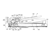
図7は画像読取部におけるプラテンローラ220周りの構成斜視図である。プラテンローラ220の両端はリードローラ217の第1搬送ローラ軸217aを支点としたプラテンアーム231に支持されており、プラテンローラ220の回転駆動は第1搬送ローラ軸217aの一端に取り付けられたプーリ217bとプラテンローラ駆動ベルト232、プーリ233を介して駆動を伝達される。プラテンアーム231の両外側には偏心カム234が取り付けられており、偏心カム234のフランジ端面にプラテンガラス108が接す
ることでプラテンローラ220面とイメージセンサ105との間隔量が定まる。偏心カム234の回転角度はアイドラギア235を介してパルスモータ236の回転角度に依存する。したがって、プラテンローラ220とイメージセンサ105の隙間量を調整する場合、パルスモータ236の回転角度を定めることで隙間量を決定することになる。この際、アイドラギア235とパルスモータ236はプラテンアーム231に併設されている。
FIG. 7 is a configuration perspective view around the
図8は偏心カム234を回転させてプラテンローラ220とイメージセンサ105の焦点距離hを調整した際プラテンローラ220の断面模式図である。通常使用する厚さの原稿を搬送する際には、読取部でのプラテンローラ220の構成は図8(a)のように偏心カム234の回転角度を設定して焦点距離Lの保持をおこなう。このときプラテンローラ220とプラテンガラス108との隙間量をhとする。もっとも薄い原稿P1を搬送する際は、図8(b)のように偏心カム234の位相を変化させてプラテンガラス108との隙間量が最も小さくなる角度へと偏心カム234を回転させて調整する。このときの隙間量をh1とする。さらに、もっとも厚い原稿P2を搬送する際は、図8(c)のように偏心カム234の位相を図8(b)の薄い原稿搬送時と180°ずらして最も隙間量がもっとも大きくなる回転角度へ調整する。このときの隙間量をh2とする。したがって、偏心カム234の偏心量Sは、S=(h1−h2)/2となる。
FIG. 8 is a schematic cross-sectional view of the
上述のように偏心カム234の回転角度を変化させて焦点距離Lが原稿坪量が変動しても常に一定となるように調整することが必要となる。
As described above, it is necessary to adjust the focal length L so that it remains constant even if the basis weight of the document fluctuates by changing the rotation angle of the
このとき本実施形態では、不図示の操作パネルより給紙トレイ201上にセットされた原稿の坪量を入力することによって、原稿厚さの情報に応じてパルスモータ236へ駆動指令を出力して偏心カム234を回転させる。この手動入力を行うことで搬送される原稿の厚さに応じたプラテンローラ220とプラテンガラス108との隙間量を調整して、原稿の坪量に対応して原稿画像面とイメージセンサ105との焦点距離をある一定の間隔に保って原稿を搬送できるようになる。
At this time, in this embodiment, by inputting the basis weight of the original set on the
以上説明したように、本実施形態の自動原稿搬送装置を備える画像読取装置によれば、原稿流し読みを行う場合において、原稿読取時に原稿Pをプラテンローラ220に押し当てて、プラテンガラス108に接することなく搬送することで、プラテンガラス108に付着性ゴミを付着させることなく原稿流し読みが行うことが可能となる。また、プラテンローラ220とプラテンガラス108との隙間より薄い原稿Pが搬送された場合でもプラテンローラ220に押し当てて搬送され、尚且つ読取装置104と原稿画像との焦点距離も一定に調整可能なため、原稿バタつき、または原稿先端のローラへの突入や原稿後端ローラ抜けによる画像ブレなどの読取動作時の外乱に対して安定した画像読み取りを行うことが可能となり、画像品位の向上が図れる。さらには、ブロアファン116および軸流ファン227により読取部近傍のプラテンローラ220にエアーを吹き付ける動作を行うことで不定期的にプラテンガラス108上に落下する落下ゴミを常に除去することが可能となり、落下ゴミによる画像劣化を完全に防止することが可能となる。加えて、プラテンローラ220へのエアー吹き付け手段は画像読取部100に併設して画像読取部100内のエアーを吸引するため長時間の原稿流し読み動作の露光による読取装置104の温度上昇を低減することも可能となる。
As described above, according to the image reading apparatus provided with the automatic document conveying device of the present embodiment, when reading a document, the document P is pressed against the
(第2実施形態)
図9、図10を参照して本実施形態について説明する。
(Second Embodiment)
This embodiment will be described with reference to FIGS.
《画像読取部の説明》
画像読取部100の基本的な構成および動作は、第1実施形態に示すものと同様であり、本実施形態で紹介する画像読取部においては、第1実施形態に紹介した画像読取部から
ブロアファンや排気ダクトといった構成を除いた構成となっている。
<< Description of Image Reading Unit >>
The basic configuration and operation of the
《原稿搬送部の説明》
次に図9、図10を参照して本実施形態の原稿搬送部200について説明する。原稿搬送部200は原稿流し読みによって原稿画像を読み取るための構成である。
<Description of the document feeder>
Next, the
原稿給紙トレイ201の上方には給送ローラ206が設けられており、分離搬送ローラ209の回転駆動に従動して原稿Pを給送する。給送ローラ206は複数セットされる原稿Pの上方から順次給送する。給送ローラ206は通常はホームポジションである上方(図中破線位置)に退避しており、原稿Pをセットする作業を妨害しないようにしている。207は原稿Pをセットする際の突き当てとなるシャッターである。シャッター207は給送ローラ206のアームとリンクしており給送ローラ206が上方にいるときは図中の位置で保持され、給紙動作が開始するとシャッター207は上方へと退避して原稿Pの進入口を開放する。給送動作が開始されると給送ローラ206は図中実線位置に下降して、原稿Pの上面に当接する。なお、給送ローラ206は不図示のアームに軸支されており、このアームを揺動させることにより上下移動される。
A
次に給送された原稿Pは分離部へ到達する。分離部は原稿Pを1枚づつ分離する分離搬送ローラ209及び分離パット211が配置されており、所定の分離圧力を発生している。分離パット211は分離搬送ローラ209より摩擦が若干小さいゴム材料などで形成される。分離搬送ローラ209は原稿を給紙する方向(図中時計回り)に駆動し、分離パット211は原稿を戻す方向へと摩擦力を発生させることで、原稿Pを一枚ずつにさばき、給送する。
Next, the fed document P reaches the separation unit. The separation unit is provided with a
分離給送された原稿Pはレジスト手段であるレジストローラ215及びレジスト従動ローラ214に送られる。静止したレジストローラ215及びレジスト従動ローラ214のニップ部に分離給紙された原稿Pの先端を突き当て、ループを生じさせることにより、原稿の先端を揃える。これにより、読み取り時の斜行を矯正することができる。そしてレジストローラ215を駆動して原稿Pを下流に搬送する。
The separated document P is sent to a
読取装置104が下方に移動してきている流し読みガラス108に向けて、リードローラ217および従動ローラ218によって原稿Pを導き、プラテンローラ220と流し読みガラス108間を搬送され、原稿Pの読み取りを開始する。読み取りが終了すると搬送ローラ222と従動ローラによって読取部から原稿Pを排出する。原稿Pの読取中は、リードローラ217と搬送ローラ222は安定した回転で駆動され、移動する原稿Pの画像を、固定した読取装置104にて画像を読み込む。
The
原稿Pの読み取りが終了し、排出ローラ224および従動ローラ225によって原稿Pは排出トレイ226上へと排出されて積載される。
The reading of the original P is completed, and the original P is discharged onto the
図10を用いて原稿搬送部におけるセンサ類とそれらに伴う原稿搬送時の動作についての説明を述べる。図10において原稿給紙トレイ201には、原稿Pがセットされたことを検知する透過型の光センサである原稿セット検知センサS1、幅方向規制板の位置を検知して原稿Pの幅方向の長さを検知する原稿幅検知センサS5(不図示)が設けられている。また、分離搬送ローラ209とレジストローラ215の間には原稿を検知する透過型の光センサであるレジストセンサS2が設けられ、分離給送された原稿の先端を検知し、レジストローラ215への突き当て量(ループ量)を制御するタイミングなどを検知している。またリードローラ217の直前に原稿Pを検知する反射型光センサであるリードセンサS3が設けられ、読取位置での読取開始タイミングの基準信号としている。また、リードセンサS3で原稿先端が検知されるとプラテンローラ220の上方に設けられている
ブロアファン229が駆動しエアダクト230を通じてプラテンローラ220周りのエアー吸引を行う。搬送される原稿Pは先端からプラテンローラ220側へと引き寄せられる。排出ローラ224の直前には原稿Pを検知する透過型光センサである排出センサS4が設けられ、原稿後端を検知しプラテンローラ220を原稿が通過し終わったことを検知してブロアファン229の動作を停止させ、さらには原稿の排出タイミングの検知している。したがって上記ブロアファン229を作動させることによって読取位置近傍を搬送される原稿Pは、エアー流によってプラテンローラ220側へ寄せられて、原稿画像面をプラテンガラス108に接せずに搬送および画像読み取りを行うことが可能となる。ブロアファン229は、原稿搬送部200におけるプラテンローラ220のプラテンガラス108に対面側とは反対側に設けられ、エアー流生成手段に含まれるエアー吸引手段であり、プラテンガラス108とプラテンローラ220との間を搬送されて読取位置を通過する原稿Pをプラテンローラ220側へ引き付けるものである。
A description will be given of the sensors in the document conveying section and the operation during document conveyance accompanying them with reference to FIG. In FIG. 10, a document set detection sensor S1, which is a transmissive optical sensor for detecting that the document P is set, is detected on the
また、上記ブロアファン229は、操作パネル(不図示)によって原稿搬送部200にセットした読取前の原稿Pの材質又は坪量、弾性力、サイズといった情報をユーザが入力することにより、入力された情報に基づいてエアー吸引量を判定しエアー吸引を制御することが可能となっている。
The
なお、プラテンローラ調整機構に関しては第1実施形態で説明した同様のものが設置されている。 The same platen roller adjustment mechanism as that described in the first embodiment is installed.
以上説明したように、本実施形態の自動原稿搬送装置を備える画像読取装置によれば、原稿流し読みを行う場合において、原稿読取時に原稿Pをプラテンローラ220に引き寄せて、プラテンガラス108に接することなく搬送することで、プラテンガラス108に付着性ゴミを付着させることなく原稿流し読みが行うことが可能となる。また、プラテンローラ220とプラテンガラス108との隙間より薄い原稿Pが搬送された場合でもプラテンローラ220に引き寄せて搬送され、尚且つ読取装置104と原稿画像との焦点距離も一定に調整可能なため、原稿バタつき、または原稿先端のローラへの突入や原稿後端ローラ抜けによる画像ブレなどの読取動作時の外乱に対して安定した画像読み取りを行うことが可能となり、画像品位の向上が図れる。さらには、ブロアファン229により読取部近傍のプラテンローラ220にエアーを吸引する動作を行うことで不定期的にプラテンガラス108上に落下する落下ゴミを常に除去することが可能となり、落下ゴミによる画像劣化を完全に防止することが可能となる。
As described above, according to the image reading apparatus provided with the automatic document conveying device of the present embodiment, when reading a document, the document P is drawn to the
100 画像読取部
104 読取装置
108 プラテンガラス
116 ブロアファン
117 排気ダクト
200 原稿搬送部
201 原稿給紙トレイ
206 給送ローラ
209 分離搬送ローラ
215 レジストローラ
217 リードローラ
220 プラテンローラ
222 搬送ローラ
224 排出ローラ
226 排出トレイ
227 軸流ファン
228 エアダクト
229 ブロアファン
230 エアダクト
100
Claims (8)
前記透明部材と間隔を保って対向して設けられ、前記透明部材との間に原稿が搬送される対向部材と、
前記透明部材と前記対向部材との間を搬送されて読取位置を通過する原稿を前記対向部材側へ寄せるエアーを流すエアー流生成手段と、
モータの駆動により前記対向部材を移動させることで前記対向部材と前記透明部材との間隔量を調整するギャップ調整手段と、
読取前の原稿の坪量が入力される情報入力手段と、
前記情報入力手段によって入力された原稿の坪量に基づいて、原稿の画像面と前記画像読取手段との間の距離が一定となるように、前記ギャップ調整手段により前記対向部材と前記透明部材との間隔量を予め決められた量に制御するギャップ調整制御手段と、
を備えることを特徴とする画像読取装置。 In an image reading apparatus that reads an image of a fed document by an image reading unit through a transparent member,
A facing member that is provided facing the transparent member at a distance, and from which the document is conveyed;
An air flow generating means for flowing an air that is transported between the transparent member and the opposing member and passes the reading position toward the opposing member;
Gap adjusting means for adjusting the distance between the opposing member and the transparent member by moving the opposing member by driving a motor ;
An information input means for inputting the grammage of the document before scanning;
Based on the basis weight of the document input by the information input unit, the gap adjusting unit causes the opposing member and the transparent member to be fixed so that the distance between the image surface of the document and the image reading unit is constant. Gap adjustment control means for controlling the interval amount to a predetermined amount;
An image reading apparatus comprising:
前記原稿端部検出手段の検出信号に基づいて前記エアー流生成手段の作動を開始させ、原稿が前記対向部材を通過している間は前記エアー流生成手段を作動させるように制御するエアー作動制御手段と、
を備えることを特徴とする請求項1に記載の画像読取装置。 A document edge detection means disposed in a document transport path upstream of the facing member in the document transport direction;
Air operation control for starting the operation of the air flow generation unit based on the detection signal of the document edge detection unit and controlling the air flow generation unit to operate while the document passes through the facing member. Means,
The image reading apparatus according to claim 1, further comprising:
前記情報入力手段によって入力された原稿情報から、前記エアー流生成手段によるエアー流量を予め決められた量に制御するエアー流量制御手段を備えることを特徴とする請求項1又は2に記載の画像読取装置。 Further, information on the material or elastic force and size of the document before reading is input to the information input means,
The image reading apparatus according to claim 1, further comprising an air flow rate control unit configured to control an air flow rate by the air flow generation unit to a predetermined amount from document information input by the information input unit. apparatus.
Priority Applications (1)
| Application Number | Priority Date | Filing Date | Title |
|---|---|---|---|
| JP2005158857A JP4603935B2 (en) | 2005-05-31 | 2005-05-31 | Image reading device |
Applications Claiming Priority (1)
| Application Number | Priority Date | Filing Date | Title |
|---|---|---|---|
| JP2005158857A JP4603935B2 (en) | 2005-05-31 | 2005-05-31 | Image reading device |
Publications (3)
| Publication Number | Publication Date |
|---|---|
| JP2006339753A JP2006339753A (en) | 2006-12-14 |
| JP2006339753A5 JP2006339753A5 (en) | 2010-01-14 |
| JP4603935B2 true JP4603935B2 (en) | 2010-12-22 |
Family
ID=37559958
Family Applications (1)
| Application Number | Title | Priority Date | Filing Date |
|---|---|---|---|
| JP2005158857A Expired - Fee Related JP4603935B2 (en) | 2005-05-31 | 2005-05-31 | Image reading device |
Country Status (1)
| Country | Link |
|---|---|
| JP (1) | JP4603935B2 (en) |
Families Citing this family (6)
| Publication number | Priority date | Publication date | Assignee | Title |
|---|---|---|---|---|
| JP4604990B2 (en) * | 2005-12-06 | 2011-01-05 | コニカミノルタビジネステクノロジーズ株式会社 | Image reader |
| JP4958639B2 (en) * | 2007-05-29 | 2012-06-20 | キヤノン電子株式会社 | Image reading device |
| JP2010190979A (en) * | 2009-02-16 | 2010-09-02 | Fuji Xerox Co Ltd | Original feeder and image reader |
| JP2010206632A (en) * | 2009-03-04 | 2010-09-16 | Ricoh Co Ltd | Image reading apparatus and copying machine |
| US9621758B2 (en) * | 2012-08-29 | 2017-04-11 | Opex Corporation | Imaging assembly for scanner |
| JP6042242B2 (en) * | 2013-03-15 | 2016-12-14 | 株式会社東芝 | Paper sheet transport device |
Citations (9)
| Publication number | Priority date | Publication date | Assignee | Title |
|---|---|---|---|---|
| JPH05300340A (en) * | 1992-04-21 | 1993-11-12 | Eastman Kodak Japan Kk | Picture input device |
| JP2000029254A (en) * | 1998-05-01 | 2000-01-28 | Ricoh Co Ltd | Automatic double-sided-document feeder |
| JP2000151913A (en) * | 1998-11-09 | 2000-05-30 | Ricoh Co Ltd | Image reader |
| JP2001048374A (en) * | 1999-08-13 | 2001-02-20 | Ricoh Co Ltd | Document reader |
| JP2003207853A (en) * | 2002-01-11 | 2003-07-25 | Nisca Corp | Image reader |
| JP2003333274A (en) * | 2002-05-14 | 2003-11-21 | Canon Finetech Inc | Document feeder and image forming device equipped with the same |
| JP2004083193A (en) * | 2002-08-27 | 2004-03-18 | Nisca Corp | Document transporting device and image reading device |
| JP2005123701A (en) * | 2003-10-14 | 2005-05-12 | Ricoh Co Ltd | Image reading apparatus |
| JP2005269235A (en) * | 2004-03-18 | 2005-09-29 | Ricoh Co Ltd | Image reading apparatus and image forming apparatus |
-
2005
- 2005-05-31 JP JP2005158857A patent/JP4603935B2/en not_active Expired - Fee Related
Patent Citations (9)
| Publication number | Priority date | Publication date | Assignee | Title |
|---|---|---|---|---|
| JPH05300340A (en) * | 1992-04-21 | 1993-11-12 | Eastman Kodak Japan Kk | Picture input device |
| JP2000029254A (en) * | 1998-05-01 | 2000-01-28 | Ricoh Co Ltd | Automatic double-sided-document feeder |
| JP2000151913A (en) * | 1998-11-09 | 2000-05-30 | Ricoh Co Ltd | Image reader |
| JP2001048374A (en) * | 1999-08-13 | 2001-02-20 | Ricoh Co Ltd | Document reader |
| JP2003207853A (en) * | 2002-01-11 | 2003-07-25 | Nisca Corp | Image reader |
| JP2003333274A (en) * | 2002-05-14 | 2003-11-21 | Canon Finetech Inc | Document feeder and image forming device equipped with the same |
| JP2004083193A (en) * | 2002-08-27 | 2004-03-18 | Nisca Corp | Document transporting device and image reading device |
| JP2005123701A (en) * | 2003-10-14 | 2005-05-12 | Ricoh Co Ltd | Image reading apparatus |
| JP2005269235A (en) * | 2004-03-18 | 2005-09-29 | Ricoh Co Ltd | Image reading apparatus and image forming apparatus |
Also Published As
| Publication number | Publication date |
|---|---|
| JP2006339753A (en) | 2006-12-14 |
Similar Documents
| Publication | Publication Date | Title |
|---|---|---|
| US11356574B2 (en) | Image reading apparatus | |
| US7577396B2 (en) | Printing apparatus | |
| JP4603935B2 (en) | Image reading device | |
| JP2005001827A (en) | Sheet transferring device and image reading device with it | |
| US10841444B2 (en) | Image reading apparatus | |
| JP2006347644A (en) | Image forming apparatus | |
| JP2021084751A (en) | Medium feeding device, image reading device, and medium feeding method in medium feeding device | |
| US7576896B2 (en) | Image processing apparatus, image reading apparatus, and document conveyance device | |
| JP6172668B2 (en) | Paper feeding device and image forming apparatus | |
| JP2008156088A (en) | Sheet conveying device and image reader | |
| JP2001309118A (en) | Original carrying device | |
| JP2013014403A (en) | Recording apparatus | |
| JP2010030718A (en) | Document conveying device and image forming device having the same | |
| JP2010089851A (en) | Image reader | |
| JP4185917B2 (en) | Image reading device | |
| JP2002232643A (en) | Original feeder and image forming device provided with this feeder | |
| JP5930605B2 (en) | Image reading apparatus and image forming apparatus | |
| JP2002232642A (en) | Original feeder and image forming device provided with this feeder | |
| JP2022189055A (en) | Sheet conveying apparatus, document reading device, and image forming apparatus | |
| JP4957626B2 (en) | Sheet conveying apparatus and image recording apparatus | |
| JP2021141377A (en) | Image reading device | |
| CN115891458A (en) | Detection apparatus, image forming apparatus, computer readable medium, and image forming method | |
| JP2005328156A (en) | Image reading apparatus | |
| JP2007105908A (en) | Paper size detecting means | |
| JP2006042193A (en) | Document carrier, document reader and image forming apparatus having the same |
Legal Events
| Date | Code | Title | Description |
|---|---|---|---|
| A621 | Written request for application examination |
Free format text: JAPANESE INTERMEDIATE CODE: A621 Effective date: 20080529 |
|
| A521 | Written amendment |
Free format text: JAPANESE INTERMEDIATE CODE: A523 Effective date: 20091124 |
|
| A977 | Report on retrieval |
Free format text: JAPANESE INTERMEDIATE CODE: A971007 Effective date: 20100406 |
|
| A131 | Notification of reasons for refusal |
Free format text: JAPANESE INTERMEDIATE CODE: A131 Effective date: 20100420 |
|
| A521 | Written amendment |
Free format text: JAPANESE INTERMEDIATE CODE: A523 Effective date: 20100621 |
|
| A131 | Notification of reasons for refusal |
Free format text: JAPANESE INTERMEDIATE CODE: A131 Effective date: 20100706 |
|
| A521 | Written amendment |
Free format text: JAPANESE INTERMEDIATE CODE: A523 Effective date: 20100906 |
|
| TRDD | Decision of grant or rejection written | ||
| A01 | Written decision to grant a patent or to grant a registration (utility model) |
Free format text: JAPANESE INTERMEDIATE CODE: A01 Effective date: 20100928 |
|
| A01 | Written decision to grant a patent or to grant a registration (utility model) |
Free format text: JAPANESE INTERMEDIATE CODE: A01 |
|
| A61 | First payment of annual fees (during grant procedure) |
Free format text: JAPANESE INTERMEDIATE CODE: A61 Effective date: 20101004 |
|
| FPAY | Renewal fee payment (event date is renewal date of database) |
Free format text: PAYMENT UNTIL: 20131008 Year of fee payment: 3 |
|
| R150 | Certificate of patent or registration of utility model |
Free format text: JAPANESE INTERMEDIATE CODE: R150 |
|
| LAPS | Cancellation because of no payment of annual fees |