JP4602343B2 - SUPPORTING BODY, HOLDING DEVICE FOR THE SUPPORTING BODY, EQUIPMENT HAVING THE MAIN BODY FOR PROCESSING WEB, METHOD FOR FORMING AN EXTENDED NIP WITH THE DEVICE, AND METHOD FOR CONTROLLING LOAD ON THE NIP - Google Patents
SUPPORTING BODY, HOLDING DEVICE FOR THE SUPPORTING BODY, EQUIPMENT HAVING THE MAIN BODY FOR PROCESSING WEB, METHOD FOR FORMING AN EXTENDED NIP WITH THE DEVICE, AND METHOD FOR CONTROLLING LOAD ON THE NIP Download PDFInfo
- Publication number
- JP4602343B2 JP4602343B2 JP2006536477A JP2006536477A JP4602343B2 JP 4602343 B2 JP4602343 B2 JP 4602343B2 JP 2006536477 A JP2006536477 A JP 2006536477A JP 2006536477 A JP2006536477 A JP 2006536477A JP 4602343 B2 JP4602343 B2 JP 4602343B2
- Authority
- JP
- Japan
- Prior art keywords
- pressure
- press
- support body
- nip
- counter
- Prior art date
- Legal status (The legal status is an assumption and is not a legal conclusion. Google has not performed a legal analysis and makes no representation as to the accuracy of the status listed.)
- Active
Links
Images


Classifications
-
- D—TEXTILES; PAPER
- D21—PAPER-MAKING; PRODUCTION OF CELLULOSE
- D21F—PAPER-MAKING MACHINES; METHODS OF PRODUCING PAPER THEREON
- D21F3/00—Press section of machines for making continuous webs of paper
- D21F3/02—Wet presses
-
- D—TEXTILES; PAPER
- D21—PAPER-MAKING; PRODUCTION OF CELLULOSE
- D21F—PAPER-MAKING MACHINES; METHODS OF PRODUCING PAPER THEREON
- D21F3/00—Press section of machines for making continuous webs of paper
- D21F3/02—Wet presses
- D21F3/0209—Wet presses with extended press nip
- D21F3/0218—Shoe presses
-
- D—TEXTILES; PAPER
- D21—PAPER-MAKING; PRODUCTION OF CELLULOSE
- D21F—PAPER-MAKING MACHINES; METHODS OF PRODUCING PAPER THEREON
- D21F3/00—Press section of machines for making continuous webs of paper
- D21F3/02—Wet presses
- D21F3/0281—Wet presses in combination with a dryer roll
Landscapes
- Paper (AREA)
- Treatment Of Fiber Materials (AREA)
- Preliminary Treatment Of Fibers (AREA)
- Fittings On The Vehicle Exterior For Carrying Loads, And Devices For Holding Or Mounting Articles (AREA)
- Bearings For Parts Moving Linearly (AREA)
- Finish Polishing, Edge Sharpening, And Grinding By Specific Grinding Devices (AREA)
- Cleaning Implements For Floors, Carpets, Furniture, Walls, And The Like (AREA)
- Fixing For Electrophotography (AREA)
Abstract
Description
本発明は、延在ニップを持つ装置用の支持本体であって、ニップは支持本体の接触表面及び対向する表面によって画成され、支持本体は弾性変形可能であり、その接触表面は対向する表面に対してこの表面との相互作用にて適合可能であり、一つの圧力チャンバ又は幾つかの圧力チャンバを含み、圧力チャンバ又は各圧力チャンバの夫々は、ニップに接触表面を介して負荷を加えるため、加圧下に置かれるように構成されている、支持本体に関する。 The present invention is a support body for an apparatus having an extended nip, the nip being defined by a contact surface and an opposing surface of the support body, the support body being elastically deformable, the contact surface being an opposing surface Including one pressure chamber or several pressure chambers, each pressure chamber or each pressure chamber for applying a load to the nip via the contact surface And a support body configured to be placed under pressure.
本発明は、更に、このような支持本体用の保持装置に関する。 The invention further relates to a holding device for such a support body.
本発明は、更に、第1構造エレメント及び移動自在に構成されており且つ延在ニップを形成するときに第1構造エレメントと相互作用するための対向する表面を持つ第2構造エレメントを含み、第1構造エレメントは移動自在の布及び対向する表面とともにニップを画成する接触表面/プレス表面を持つ弾性変形可能な支持本体/プレス本体を含み、この支持本体/プレス本体の接触表面/プレス表面は、対向する表面に対してこの表面との相互作用にて適合でき、圧力チャンバ又は幾つかの圧力チャンバを含み、圧力チャンバ又は各圧力チャンバの夫々は、接触表面/プレス表面を介してニップに負荷を加えるため、圧力が加わった状態に置かれように構成されている、抄紙機又は板紙抄紙機で製造される繊維ウェブを処理するための装置/プレスに関する。 The present invention further includes a first structural element and a second structural element configured to be movable and having an opposing surface for interacting with the first structural element when forming an extended nip, One structural element includes a movable body and an elastically deformable support body / press body having a contact surface / press surface defining a nip with an opposing surface, the contact body / press surface of the support body / press body being Can be adapted to interact with this surface against an opposing surface, including a pressure chamber or several pressure chambers, each of which is loaded into the nip via a contact surface / press surface For processing a fibrous web produced on a paper machine or board machine, configured to be placed under pressure About the press.
本発明は、更に、装置で延在ニップを形成する方法であって、接触表面を持つ支持本体を含み、ニップは接触表面及び対向する表面によって画成され、支持本体は弾性変形可能であり、その接触表面は対向する表面に対してこの表面との相互作用にて適合でき、圧力チャンバ又は幾つかの圧力チャンバを含み、圧力チャンバ又は各圧力チャンバは、夫々、接触表面を介してニップに負荷を加えるため、圧力が加わった状態に置かれるように構成されている、方法に関する。 The present invention further includes a method of forming an extended nip with an apparatus, comprising a support body having a contact surface, the nip being defined by a contact surface and an opposing surface, the support body being elastically deformable, The contact surface can be adapted to interact with this surface relative to the opposing surface and includes a pressure chamber or several pressure chambers, each of which is loaded into the nip via the contact surface. The method is adapted to be placed under pressure to apply a pressure.
本発明は、更に、接触表面を持つ支持本体を含む装置の延在ニップでの負荷を制御する方法であって、ニップは接触表面及び対向する表面によって画成され、複数の圧力チャンバを持つ支持本体は弾性変形し、支持本体の接触表面は、対向する表面との相互作用で対向する表面に適合でき、ニップには、圧力チャンバを加圧することによって接触表面を介して負荷が加えられる、方法に関する。 The present invention is further a method for controlling loading at an extended nip of a device that includes a support body having a contact surface, the nip being defined by the contact surface and the opposing surface and having a plurality of pressure chambers. The body is elastically deformed, the contact surface of the support body can be adapted to the opposing surface by interaction with the opposing surface, and the nip is loaded through the contact surface by pressurizing the pressure chamber About.
延長プレスニップを持つ従来既知のプレスは、アルミニウムや鋼等の金属材料でできたいわゆるプレスシューを有する。このプレスシューは、通常は凹状のプレス表面を持つように設計されている。プレス表面は対向するカウンタ圧力表面と非常に正確に適合する。このようなプレスシューは、製造が非常に複雑であり、及び従って、非常に費用がかかる。金属で形成されているため、比較的剛性であり且つ非可撓性である。このようなプレスシューのカウンタロールとして作用するプレスロールは、シリンダ壁が比較的厚く、プレスシューからの力に耐える。カウンタロールの別の例によれば、比較的薄いシリンダ壁を有し、この薄く及びかくして変形可能なシリンダ壁又はシェルを、所望の負荷を得るためにプレスシューがカウンタロールに加えなければならない力に応じて調節自在にクラウニング(crowing)するためのカウンタ圧力システムを内部に備えている。更に、プレスシューが、カウンタロールのクラウンに従ったクラウンを備えているのがよく、その場合、このカウンタロールとの組み合わせのみで使用できる。別の態様では、液圧シリンダによって金属製プレスシューを傾けることができる。 A conventionally known press having an extended press nip has a so-called press shoe made of a metal material such as aluminum or steel. This press shoe is usually designed to have a concave press surface. The press surface fits very accurately with the opposing counter pressure surface. Such press shoes are very complex to manufacture and are therefore very expensive. Because it is made of metal, it is relatively rigid and inflexible. The press roll acting as a counter roll of such a press shoe has a relatively thick cylinder wall and withstands the force from the press shoe. According to another example of a counter roll, this thin and thus deformable cylinder wall or shell having a relatively thin cylinder wall is the force that the press shoe must apply to the counter roll to obtain the desired load. A counter pressure system is provided inside for adjustable crowning. Furthermore, the press shoe is preferably provided with a crown according to the crown of the counter roll, in which case it can only be used in combination with this counter roll. In another aspect, the metal press shoe can be tilted by a hydraulic cylinder.
ヤンキーシリンダは、比較的薄いシリンダ壁又はシェルを有し、ヤンキーシリンダをカウンタロールとして使用した場合、プレスシューの窪みにより容易に変形する。シェルの変形は、軸線方向で、中央領域から端壁に向かう方向で変化する。端壁では、窪みは中央領域内よりもかなり小さい。従って、プレスシューは、端壁で又はその近くで増大された圧力で作用し、その結果、プレスフェルトの縁部の磨耗が増大し、プレスシューに沿った負荷プロファイルが不規則になり、紙の性質が機械方向に対して横方向で変化する場合がある。内部カウンタ圧力システムによってヤンキーシリンダのシェルにクラウンを施すこと、又はプレスシューに作用を及ぼし、変形した表面と形態を一致するため、プレスシューの下側に二列又はそれ以上の液圧シリンダを配置することが提案されてきた。これらは両方とも、負荷プロファイルを更に均等にするためである。しかしながら、これらの提案は、両方とも複雑であり、実施するのに費用がかかる。 The Yankee cylinder has a relatively thin cylinder wall or shell, and when the Yankee cylinder is used as a counter roll, it is easily deformed by the depression of the press shoe. The deformation of the shell changes in the axial direction, from the central region toward the end wall. At the end wall, the depression is much smaller than in the central region. Thus, the press shoe acts at an increased pressure at or near the end wall, resulting in increased wear on the edge of the press felt, resulting in an irregular load profile along the press shoe, Properties may change in a direction transverse to the machine direction. Two rows or more of hydraulic cylinders are placed under the press shoe to crown the Yankee cylinder shell with the internal counter pressure system or to act on the press shoe to match the deformed surface It has been proposed to do. Both of these are to make the load profile even more uniform. However, both of these proposals are complex and expensive to implement.
以下の文献は、延長プレスニップを持つプレスの例である。 The following document is an example of a press with an extended press nip.
ドイツ国特許第DE 44 05 587号及びWO 02/44467には、プレスシュー3又は同じ設計のダブルプレスシュー3a、3bを含む液圧式支承体を持つプレスが記載されている。プレスベルト6がプレスシュー3の潤滑流体床の上で非常に小さい摩擦で転動する。金属製のプレスシューは、好ましくは水である液圧流体が入った圧力チャンバ10を有する。適当な固体材料、好ましくはステンレス鋼製の矩形の圧力等化膜20がプレスシューのプレスニップ側に固定されている。圧力等化膜20は、外縁部26、内縁部22、及び内縁部22が画成する開口部27を有する。かくしてフレームのように見える圧力等化膜20は可撓性であり、そのため、その二つの側部の間で圧力差が発生したとき、液圧流体と直接接触した状態を保持した縁部ゾーン21が撓むことができる。これらの圧力差は、紙ウェブ及び/又はカウンタロールの包絡面の凹凸により液圧流体がプレスニップを通って漏出したときに発生する。かくして、可撓性圧力等化膜20は、液漏れがないか或いはほんの僅かな自動調節ニップ2を形成する。かくして、圧力チャンバ10内の圧力流体は、圧力等化膜20の開口部27を通って移動自在のベルトと直接接触した状態を保持する。前記WO刊行物を前記DE刊行物と比較して行われた補足的追加は、ベルトの潤滑を行うために圧力チャンバ10からベルト6に液圧流体を導くため、可撓性膜の自由縁部ゾーン21に「ピンホール25」を設けることである。
米国特許第5,980,693号には、チューブ状の少なくとも一つの膨張可能な負荷エレメントを持つが、負荷エレメントとベルトの内側との間に金属シューがないプレスが記載されている。更に、シューのこの部分は、ニップ出口の圧力をゆっくりと減少するために構成されている。通常は、圧力がいきなり低下するのが望ましい。 U.S. Pat. No. 5,980,693 describes a press having at least one inflatable load element in the form of a tube, but without a metal shoe between the load element and the inside of the belt. In addition, this portion of the shoe is configured to slowly reduce the pressure at the nip outlet. Usually, it is desirable that the pressure suddenly decreases.
米国特許第3,839,147号には、二つの対向するシューを持つシュープレスが記載されている。各シューは、ベルトの内側に対してシールする金属製底部及び下台を有する。ベルトに面するシューの側部は有孔膜であり、これにより圧力チャンバ内の液圧流体の圧力でベルトの内側を直接押圧する。シューは、比較的複雑な構造であり、様々な孔及び強化体を含む。 U.S. Pat. No. 3,839,147 describes a shoe press having two opposing shoes. Each shoe has a metal bottom and lower base that seals against the inside of the belt. The side of the shoe facing the belt is a perforated membrane, which directly presses the inside of the belt with the pressure of the hydraulic fluid in the pressure chamber. The shoe is a relatively complex structure and includes various holes and reinforcements.
米国特許第5,951,824号には、通常の液圧負荷エレメントを持つ通常のシューが記載されている。シューは、プレスニップを通過する紙の塊(paper wads)がシューやベルトを損傷しないようにするため、ポリマー又はゴムでできた柔らかく且つ丈夫な層でコーティングしてある。 U.S. Pat. No. 5,951,824 describes a conventional shoe with a conventional hydraulic load element. The shoe is coated with a soft and durable layer made of polymer or rubber so that paper wads passing through the press nip do not damage the shoe or belt.
欧州特許第EP 0 575 353号には、金属製カバーの内側にベローズが配置され、ベルトが前記金属製カバーの周囲を摺動するシューを持つプレスが記載されている。 European Patent No. EP 0 575 353 describes a press having a shoe in which a bellows is arranged inside a metal cover and a belt slides around the metal cover.
米国特許第6,334,933号には、金属プレート及びホースによってシールされた複数の圧力ポケットが設けられた金属製カウンタパートを持つプレスが記載されている。このプレスもまた、プレスニップの対向する部分に負荷を加えるのに役立つ。 US Pat. No. 6,334,933 describes a press having a metal counter part provided with a plurality of pressure pockets sealed by a metal plate and hose. This press also helps to load the opposing parts of the press nip.
米国特許第6,387,216号には、上側をベルトが走行し、プレスニップに負荷を加える開放流体チャンバを持つプレスが記載されている。チャンバは、ベルトに圧力を加えることによってシールされ、そのため、チャンバの縁部上に締め付けられる。 U.S. Pat. No. 6,387,216 describes a press with an open fluid chamber in which a belt runs on top and applies a load to the press nip. The chamber is sealed by applying pressure to the belt and is therefore clamped on the edge of the chamber.
欧州特許第EP 1 319 744号には、プレスニップの計測穴の上方の基準点での液圧静圧を計測し、連続的に適合することによって、プレスシューのニップ圧力をウェブに対して横方向に及びウェブに沿って計測し、調節するための方法が記載されている。 European Patent No. EP 1 319 744 measures the hydrostatic pressure at a reference point above the measurement hole of the press nip and continuously adapts it so that the nip pressure of the press shoe is transverse to the web. A method for measuring and adjusting in the direction and along the web is described.
ドイツ国特許第DE30 30 233号には、金属製スタンドに取り付けられた弾性スライドシューが記載されている。スライドシューは、スライド本体、即ち圧力媒体で充填できるホースの形態の中空本体を含む。ホースは、金属製スタンドに取り付けられた弾性ベルトによって取り囲まれている。中空本体は、様々な圧力に加圧できるチャンバに分割できる。しかしながら、一つ又はそれ以上のチャンバ内の圧力が変化してもニップでの負荷を変化させることはない。これは、中空本体がこのような圧力上昇の度毎に横方向に膨張できるためである。 German patent DE 30 30 233 describes an elastic slide shoe attached to a metal stand. The slide shoe comprises a slide body, ie a hollow body in the form of a hose that can be filled with a pressure medium. The hose is surrounded by an elastic belt attached to a metal stand. The hollow body can be divided into chambers that can be pressurized to various pressures. However, changing the pressure in one or more chambers does not change the load at the nip. This is because the hollow body can expand laterally for each such pressure increase.
本発明の目的は、既知の支持本体に関して、特別な機械加工や、作用を及ぼす対向表面の形状に対する主要な配慮なしに更に簡単に製造でき、一つ又はそれ以上の圧力チャンバ内の圧力に応じて、走行するベルトによって閉鎖される一つ又はそれ以上の圧力ポケット列を持つ従来の金属製支持本体で可能であるのと同様に、又はそれよりも良好な方法で所定の負荷プロファイルを提供できる、弾性支持本体を提供することである。 The object of the present invention is that it can be manufactured more easily for a known support body without special machining or major considerations for the shape of the acting counter surface, depending on the pressure in one or more pressure chambers. Can provide a predetermined load profile in a manner similar to or better than that possible with conventional metal support bodies having one or more rows of pressure pockets closed by a traveling belt. It is to provide an elastic support body.
本発明による支持本体は、一つの圧力チャンバ又は複数の圧力チャンバの夫々の前記接触表面に面する側を除き、一つの圧力チャンバ又は複数の圧力チャンバの夫々用のカウンタ支持体を形成するように構成された保持装置が設けられていることを特徴とする。 The support body according to the invention forms a counter support for each of the pressure chambers or of the plurality of pressure chambers, except for the side facing the contact surface of each of the pressure chamber or of the plurality of pressure chambers. A structured holding device is provided.
本発明による保持装置は、支持本体の全ての表面について、周方向に見て、そのカウンタ表面を除き、外カウンタ支持体を形成するため、支持本体を受け入れるための空間を有し、前記接触表面に面する側を除いて一つの圧力チャンバ又は複数の圧力チャンバの夫々用の内カウンタ支持体を形成するため、支持本体全体又はその一部が埋設されることを特徴とする。 The holding device according to the present invention has a space for receiving the support body to form an outer counter support, except for the counter surface, as viewed in the circumferential direction, on all surfaces of the support body, the contact surface In order to form an inner counter support for one pressure chamber or each of a plurality of pressure chambers except for the side facing the surface, the entire support body or a part thereof is embedded.
本発明による装置は、一つの圧力チャンバ又は複数の圧力チャンバの夫々の前記接触表面に面する側を除き、一つの圧力チャンバ又は複数の圧力チャンバの夫々用のカウンタ支持体を形成するように構成された保持装置が支持本体に設けられており、これによって前記装置及びニップ形成作動位置にある支持本体の作動時に、前記支持本体は、前記一つの圧力チャンバ又は前記幾つかの圧力チャンバのうちの少なくとも一つの圧力の変化によりニップ内の圧力を付随して変化する圧力曲線に従って対応して変化するように構成されていることを特徴とする。 The device according to the invention is arranged to form a counter support for each of the pressure chamber or of the plurality of pressure chambers except for the side facing the contact surface of each of the pressure chamber or of the plurality of pressure chambers. A holding device is provided on the support body, so that upon operation of the device and the support body in the nip forming operating position, the support body is one of the one or several pressure chambers. It is characterized in that the pressure in the nip is correspondingly changed according to a pressure curve that changes accompanying the change in at least one pressure.
本発明によるプレスは、一つの圧力チャンバ又は複数の圧力チャンバの夫々に対し、一つの圧力チャンバ又は複数の圧力チャンバの夫々の前記プレス表面に面する側を除き、カウンタ支持体を形成するように構成された保持装置がプレス本体に設けられており、これによって前記プレス及びニップ形成作動位置にあるプレス本体の作動時に、プレス本体は、前記一つの圧力チャンバ又は前記幾つかの圧力チャンバのうちの少なくとも一つの圧力の変化によりニップ内の圧力を付随して変化する圧力曲線に従って対応して変化するように構成されていることを特徴とする。 The press according to the invention forms a counter support for each of the pressure chamber or the plurality of pressure chambers, except for the side of the pressure chamber or the plurality of pressure chambers facing the pressing surface. A configured holding device is provided in the press body so that when the press body in the press and nip forming operating position is operated, the press body is one of the one or several pressure chambers. It is characterized in that the pressure in the nip is correspondingly changed according to a pressure curve that changes accompanying the change in at least one pressure.
延在ニップを形成する本発明による方法は、
− 支持本体の上部分及び側部分用のカウンタ支持体を形成する保持装置に支持本体を取り付ける工程、
− 前記一つの圧力チャンバ又は前記幾つかの圧力チャンバのうちの少なくとも一つに増大された圧力を加える工程、及び
− 弾性変形可能であり且つ前記上部分に連結された支持本体の前記側部分の膨張によって、前記接触表面を構成する支持本体の上部分を、前記増大された圧力の作用で、対向する表面に向かう方向で移動する工程を含む、ことを特徴とする。
The method according to the invention for forming an extended nip comprises:
-Attaching the support body to a holding device forming a counter support for the upper and side parts of the support body;
Applying an increased pressure to at least one of the one pressure chamber or the several pressure chambers; and- of the side portion of the support body that is elastically deformable and connected to the upper portion And moving the upper part of the support body constituting the contact surface in the direction toward the opposite surface under the action of the increased pressure by expansion.
延在ニップの負荷を制御する本発明による方法は、
− 支持本体の下部分及び側部分用のカウンタ支持体を形成する保持装置に支持本体を取り付ける工程、及び
− 圧力チャンバ内の圧力を所定のパターンに従って設定し、所望の圧力曲線を得る工程を含む、ことを特徴とする。
The method according to the invention for controlling the load on the extended nip comprises:
-Attaching the support body to the holding device forming the counter support for the lower and side parts of the support body; and-setting the pressure in the pressure chamber according to a predetermined pattern to obtain a desired pressure curve It is characterized by that.
「ニップ」という表現は、ワイヤ及び支持本体が画成するニップを含むように、その最も広い意味で解釈されるべきである。 The expression “nip” should be taken in its broadest sense to include the nip defined by the wire and the support body.
下文において、本発明を添付図面を参照して更に詳細に説明する。 In the text which follows, the invention will be described in more detail with reference to the accompanying drawings.
本発明を繊維ウェブを脱水するためのプレスと関連して説明する。当然のことながら、本発明は、プレスセクションの他に、繊維ウェブを処理するための任意の適当な装置、例えば抄紙機又は板紙抄紙機の乾燥セクション又は形成セクションの装置、及び繊維ウェブの表面処理を行うためのカレンダーの装置に適用できる。 The present invention will be described in connection with a press for dewatering a fibrous web. Of course, in addition to the press section, the present invention provides any suitable equipment for treating the fiber web, such as the equipment of the drying or forming section of a paper machine or board machine, and the surface treatment of the fiber web. It can be applied to a calendar device for performing
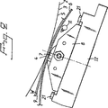
図1及び図2は、形成された湿潤状態の繊維ウェブから水を絞り出すために抄紙機又は板紙抄紙機のプレスセクションに配置されたプレスの部分を概略に示す。有利には、本発明は、ティッシュ抄紙機型の抄紙機で使用できる。プレスは、第1プレスエレメント1及び第2プレスエレメント2を含む。これらのプレスエレメント1、2は、延長プレスニップNを形成するため、互いに相互作用する。 1 and 2 schematically show a portion of a press placed in the press section of a paper machine or paperboard machine to squeeze water out of the formed wet fibrous web. Advantageously, the present invention can be used in tissue paper machine type paper machines. The press includes a first press element 1 and a second press element 2. These press elements 1, 2 interact with each other to form an extended press nip N.
第2プレスエレメント2は、プレスニップNで作用するカウンタ圧力部材を含み、この部材は、移動自在の無端表面3を有する。この無端表面は、湾曲していてもよいし直線状であってもよい対向表面即ちカウンタ圧力表面4をプレスニップN内に形成する。プレスの図示の実施形態では、第2プレスエレメント2は、プレスロールの形態のカウンタロールを含む。このカウンタロールは、更に、従来の乾燥セクションの乾燥シリンダ即ちヤンキーシリンダとして設計されたティッシュ抄紙機の乾燥シリンダであってもよい。この場合、カウンタ圧力部材は、カウンタロール2の円筒壁5を含み、その包絡面が前記移動自在の無端表面3を形成する。これは、延長プレスニップN内で前記カウンタ圧力表面4を形成する。これは、室温であってもよいし加熱によって温度を上げてもよい。シリンダ壁5が厚く且つ十分に安定している場合には、カウンタ圧力部材を構成する。シリンダ壁5が薄く変形可能である場合には、カウンタ圧力部材は、必要なカウンタ力を提供する内部支持システム(図示せず)を更に含む。
The second press element 2 includes a counter pressure member acting at the press nip N, which member has a movable
第1プレスエレメント1は、可撓性材料でできた移動自在の無端ベルト6、プレス本体の形態の支持本体7、プレス本体7を取り付けるための保持装置8、この保持装置8を取り付けるための支持本体、プレス本体7を作動するための負荷手段を含む。移動自在のベルト6は閉ループを描き、その内側にプレス本体7及び支持本体が配置される。移動自在のベルト6は、延長プレスニップNを通過するときに脱水されるべき湿潤状態の繊維ウェブWを搬送するプレスフェルト9とプレスニップNの前で出会うように配置されている。負荷手段は、プレス本体7がベルト6、プレスフェルト9、及びウェブWを介してカウンタロール2に及ぼす圧力を得るため、プレスの作動中にプレス本体7に影響を及ぼすために、作動されるように配置されている。プレス本体7は、機械方向で見たときの延長プレスニップNの長さを決定するように構成されている。プレス本体7は、プレスの作動中に回転ベルト6が摺動接触する自由摺動表面10を有する。これによって、摺動表面10は、接触表面即ちプレス表面13の全体又は一部を形成する。これは、前記カウンタ圧力表面4ともにプレスニップNを画成する。回転ベルト6とプレス本体7との間の摩擦を減少する薄膜を形成するためにベルトの内側に潤滑剤を供給するため、スプレー装置11がプレス本体7の上流に取り付けられている。
The first press element 1 comprises a movable endless belt 6 made of a flexible material, a
プレスの図示の実施形態では、第1プレスエレメント1はプレスロールを含み、そのシェルが移動自在のベルト6を形成する。このベルトは、かくして、実質的に円形のループを描く。プレスの変形例(図示せず)では、可撓性の移動自在のベルトが非円形ループをなして、例えば実質的に楕円形のループをなして、又は実質的に三角形のループをなして、プレス本体及び一つ又は幾つかのガイドロールの周囲を走行するように構成されている。図示の実施形態では、プレスロール1は二つの円形の回転自在に取り付けられた端壁(図示せず)を有し、これによって、シェル6は、これらの壁とともに回転するため、端壁の周囲にしっかりと取り付けられている。シェル6及び端壁は閉鎖空間を画成し、この空間に支持本体が配置される。この支持本体は、端壁間をこれらと接触せずに軸線方向に延びる定置の支持ビーム12を含む。プレス本体7及びその保持装置8もまた、端壁間をこれらと接触せずに軸線方向に延びる。別の態様では、第2プレスエレメントは、上文中に説明した第1プレスエレメント1と同じ又は実質的に同じ設計であってもよい。これによって、プレスニップは、かくして、本発明による二つのプレス本体によって形成される。
In the illustrated embodiment of the press, the first press element 1 comprises a press roll whose shell forms a movable belt 6. This belt thus draws a substantially circular loop. In a press variant (not shown), the flexible movable belt forms a non-circular loop, for example a substantially elliptical loop, or a substantially triangular loop, It is configured to run around the press body and one or several guide rolls. In the illustrated embodiment, the press roll 1 has two circular, rotatably mounted end walls (not shown), so that the shell 6 rotates with these walls, so that the periphery of the end wall It is firmly attached to. The shell 6 and the end wall define a closed space in which the support body is arranged. The support body includes a
プレス本体7は弾性変形可能であり、そのプレス表面13をカウンタ圧力表面4にこの表面との相互作用にて適合できる。この適合は、前記負荷手段が生成し、プレス本体7にカウンタ圧力表面4に向かう方向で作用する負荷の作用で行われ、これによってプレスニップN全体に負荷を加える。プレス本体7が弾性変形可能であるということの定義は、必ずしもプレス本体全体が弾性材料で形成されているということを意味するものではなく、本発明では広い意味で理解されるべきであり、即ちプレス本体は、弾性材料でできた少なくとも一つの機能部分を持つと理解されるべきであり、これにより定義が満たされる。実際上の及び生産技術的理由により、及び最も好ましい実施形態によれば、プレス本体はその全体が一つ(又は幾つかの)の弾性材料で形成されている。
The
本発明によれば、プレス本体7は一つ又は幾つかの閉鎖圧力チャンバを含む。これらの圧力チャンバは前記負荷手段の部分である。図5によれば、プレス本体7は単一の大きな圧力チャンバ14を含み、このチャンバは、プレス表面13の対向プレスゾーン15を画成する。プレス本体7及びその保持装置8は、図1によるプレスの部分であり、図3及び図4に更に詳細に示してあるが、これらの二つの構造エレメントは、図6及び図7及び図5に夫々別々に示してある。図5で明らかなように、保持装置8は細長いビーム形状ホルダ22を含む。このホルダは、形態が安定しており、二つの側支持部分17、18及びこれらの側支持部分を連結する下支持部分19によって画成されたU形状又は矩形の断面を持つ軸線方向貫通チャンネル16が設けられている。ホルダ22を図2に示すように支持ビーム12にボルト21で取り外し自在に固定するため、両取り付けフランジ20が側支持部分17、18に形成されている。保持装置は、ホルダ22の平行な両端面に取り外し自在に取り付けるための二つの端プレート23並びに側支持部分17、18の頂部に取り外し自在に取り付ける二つのクランププレート24を含むということが図3から明らかである。図3及び図4から明らかなように、プレスニップNの入口に配置されるようになった側支持部分17には、プレス本体7を露呈するため、クランププレート24間を延びる凹所25が設けられている。一方の端部プレート23の中央には、好ましくは液圧オイルである気体又は液体形態の圧力媒体用の入口を形成する連結部材26が位置決めされている。他方の端部プレート23には、液圧オイルを使用した場合に圧力チャンバ14を脱気するための出口を形成する同様の連結部材27が設けられている。
According to the invention, the
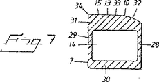
図6及び図7は、ホルダ22のチャンネル16に取り付けられるようになったプレス本体7を示す。このプレス本体は、対向する横面間に遊びが生じないように、及びプレス本体7の下面がチャンネル16の下面に載止するように、チャンネル16の断面と適合する断面を有する。この実施形態では、プレス本体7には通孔が設けられている。この通孔は、全体に矩形断面の圧力チャンバ14を形成するため、両端がシールされるようになっている。この圧力チャンバ14は、プレス本体7の二つの平行な側壁28、20、下壁30、及び上壁31によって画成される。図6及び図7に示す実施形態では、二つの側壁28、29は同じ厚さを有する。上壁31は前記自由摺動表面10を形成する。この自由摺動表面がカウンタロール2に面する。これにより、作動中、回転ベルト6が摺動接触する。断面図では、摺動表面10は、所定半径の初期湾曲表面部分32を形成するため、所定の円弧形状を持つように設計されている。表面部分33は湾曲表面部分32に対して接線をなし、尖った隅部34まで上方に延びている。摺動表面10は隅部のところに側壁29の外側を形成し、機械方向で固定される。湾曲した表面部分32の目的は、ベルト6と摺動表面10との間で薄膜を形成するときにベルト6の内側に潤滑剤を付けることができるようにするため、回転ベルト6と湾曲表面部分32との間に楔形を形成することである。上述の隅部34はプレスニップNの出口を形成し、湾曲表面部分32のところのプレスニップNの入口は、圧力チャンバ14内の圧力に応じて浮動する。プレス本体7の端部分35には摺動表面10が設けられていない。これは、上壁31をここで狭幅にし、即ち凹所を形成し、均等にすることによって行われる。端部分35により、図2及び図3から明らかなように、ホルダ22に前記クランププレート24で簡単に取り外し自在に取り付けることができる。従って、このアッセンブリでは、二つの連結部材26、27が圧力チャンバ14内に延びている。端プレート23及び連結部材26、27に対して圧力チャンバ内部をシールするため、圧力チャンバ14の端部分35にカップ状シール(図示せず)が配置してある。図1乃至図7による図示の実施形態では、負荷手段は、前記圧力チャンバ14、及び配管37及び前記連結部材26を介して圧力チャンバ14に連結された圧力媒体源36を含む。圧力チャンバ14内の圧力は、適当な制御装置38によって調節される。
6 and 7 show the
上述のように、プレス本体7は弾性変形可能である。これは、圧力チャンバ14内の増大する圧力の作用で膨張し、上壁31をそのプレス表面13とともにカウンタロールのカウンタ圧力表面4に向かう方向で押圧できるようにするためである。図6及び図7から明らかなように、プレス本体7は弾性材料で一部品に形成されている。プレス本体7は、開始位置では、そのプレス表面13が、対向するカウンタ圧力表面4と接触しない所定のところに配置される。プレスを作動させると、圧力チャンバ14内の圧力が上昇し、ニップ形成作動位置をとる。圧力上昇により、プレス本体7を、保持装置8に関し、カウンタロール2のカウンタ圧力表面4に向かう方向で弾性的に膨張する。これは、側壁28、29が、カウンタロール2のカウンタ圧力表面4から反力が発生するまで、弾性的に自由に延びる即ち膨張するためである。反力は、先ず最初にプレスニップの出口のところ、即ち側壁28のちょうど反対のところに現れ、次いで、プレスニップの入口に向かう方向で連続的に伝播する。プレスニップの入口の位置は、所望の負荷に対して予め設定された最大圧力値で決まる。従って、プレス本体7の前記弾性膨張中、上壁31、及びこの上壁31に当接した回転ベルト6がカウンタロール2に向かう方向で押圧され、上壁31は、カウンタ圧力表面4の形状に応じて機械方向MD及び機械方向に対して横方向CDの両方向で弾性変形する、即ちプレス表面13の形態がカウンタ圧力表面4の輪郭と一致し、即ち適合し、プレスニップを画成する摺動表面10即ちプレス表面13の部分の形態がカウンタロール2の対向するカウンタ圧力表面4に従って変化する。プレス表面は、この場合、前記プレスゾーン15と対応する。別の態様では、プレス本体7は、そのプレス表面13が対応するカウンタ圧力表面4から無接触距離にある第1開始位置に取り付けられる。プレス本体7及び保持装置8は、適当な移動伝達装置によって、第1開始位置から、プレス本体7のプレス表面13が対向するカウンタ圧力表面4と接触した又はほぼ接触した第2開始位置まで一緒に移動する。次いで、ニップ形成作動位置をとるため、圧力チャンバ内の圧力を所望の圧力曲線に従って増大させる。
As described above, the
図1乃至図7による実施形態で使用したプレス本体7は、図8に示す負荷プロファイル又は圧力曲線を示す。
The
更に、図9による実施形態では、プレス本体7は一部品で形成されているが、上流側壁28が下流側壁29よりも僅かに厚い。これによって、圧力を圧力チャンバ14に加えたときの弾性膨張に対する抵抗は厚い方の側壁28が薄い方の側壁29よりも大きい。これは、プレスニップNの初期部分に作用する圧力が、プレスニップの最終部分よりも小さくなり、そのため負荷プロファイル又は圧力曲線が、図10に示すように比較的平らな経路を辿るということを意味する。この効果は、下流側壁の方が上流側側壁よりも弾性であり且つ伸長性が高いように側壁を厚さが等しいが弾性率が異なる材料で形成することによっても得ることができる。
Furthermore, in the embodiment according to FIG. 9, the
図11は、両端がシールされた円形断面を持つ弾性ホース形態のプレス本体7を示す。内部空間が圧力チャンバ60を形成する。保持装置8のチャンネル16は、対応する又は実質的に対応する円形形状を有し、そのため、円形のチャンネル壁は、圧力を加えて膨張させたときにホースに対してカウンタ支持体を形成し、上自由部分即ち上壁31が上方に開放したチャンネル16を通って押し出され、本発明の原理に従って支持体を形成する。
FIG. 11 shows a
図12は、図7に示したものと同様であるが、弾性変形可能な二つの長さ方向垂直隔壁39が設けられたプレス本体7を示す。これらの隔壁は、従って、側壁28、29と平行であり、三つの小さな圧力チャンバ40を画成する。これらの圧力チャンバは、ニップ内の負荷を調節するため、これらのチャンバを互いに独立した異なる圧力P1、P2、及びP3に置くことができるように、圧力媒体源36に連結されている。例えば、圧力関係は、P1<P2<P3であるように選択でき、この場合、この例によるプレス本体7は、図13に示すような段階的負荷プロファイル又は圧力曲線を示す。各圧力チャンバ40は、プレス表面13の対向プレスゾーン41を画成する。
FIG. 12 shows a
図14は、図12に示したものと同様であるが、二つの圧力チャンバ62を画成する弾性変形可能な長さ方向垂直隔壁61が設けられたプレス本体7を示す。圧力チャンバは、ニップ内の負荷を調節するため、互いに独立した異なる圧力に置くため、圧力媒体源36に連結されている。隔壁61は、二つの圧力チャンバ間に大きな圧力差がある場合でも隔壁が撓まないようにするために、比較的厚い。
FIG. 14 shows a
図15は、図14に示したものと同様であるが、下壁30からこの下壁を通って上方に隔壁全体に亘って延び、これによって隔壁を二つの小さな壁部分に分割する下方に開放した溝63が設けられたプレス本体7を示す。保持装置8は、チャンネル16の底部から上方に延びる、溝63と対応する矩形断面の強化壁65を持つように設計されている。強化壁65は、例えば形状が永久的な保持装置8と一体成形することによって、剛性材料でできている。強化壁65は、大きな圧力差が存在する場合に二つの圧力チャンバ62内の圧力が隔壁61を介して互いに影響を及ぼし合うことがないようにする。隔壁によるこのような強化は、形態安定正方形輪郭(図示せず)によっても得ることができる。これは、例えば図12に従ってプレス本体の各圧力チャンバ内に配置され、圧力チャンバの全ての表面を支持し、プレス表面13に面する輪郭の側部には、圧力チャンバ内の圧力を上壁31に作用できるように孔又は穴が設けられている。
FIG. 15 is similar to that shown in FIG. 14, but extends downward from the
図16は、図12に示したものと同様であるが、弾性変形可能な四つの長さ方向垂直隔壁39が設けられたプレス本体7の一部を示す。図16から明らかなように、プレス本体7には、更に、弾性変形可能な複数の横方向垂直隔壁42が設けられており、これらの横方向隔壁は互いに対してずらしてあり、長さ方向隔壁39とともに複数の隔室状圧力チャンバ43を画成する。これらの隔壁は、ニップ内の負荷を調節するため、セクション又は群によって互いに別個に異なる圧力に置くことができるようにするため、圧力媒体源36に連結されている。図示の例では、隔室43は、異なる圧力p1、p2が作用する二つの群をなして配置されている。隔室群の圧力関係は、例えば、p1<p2である。高い方の圧力p2が作用する隔室43の群には、図17で破線が付してある。
FIG. 16 is the same as that shown in FIG. 12, but shows a part of the
図18は、図6及び図7に示したものと同様であるが、二つの部品でできており、図6及び図7に示したものと同様の圧力チャンバ56を画成するプレス本体7を示す。一方の部品は、プレス本体の二つの側壁28、29及び下壁30を含むのに対し、他方の部品はプレス本体の上壁を含み、薄い層即ち膜54の形態を示す。側壁28、29は、膜54をその縁部に沿って固定するためのフランジ部分55を持つように設計されている。図18のプレス本体7は、図6及び図7に示したものと同様に機能する。第1部品28、29、30は弾性材料でできている。膜54は任意の材料でできていてもよく、弾性の低い材料、例えば金属でできていてもよく、プレス表面13をカウンタ圧力表面4と適合させるため、側壁28、29の膨張時に変形でき、圧力チャンバ56内の圧力を減少したときに側壁28、29の引張力が作用を停止したとき、その最初の位置に戻る。
FIG. 18 is similar to that shown in FIGS. 6 and 7, but is made up of two parts, the
支持本体7が複数の圧力チャンバを有する場合(図12及び図14の実施形態のように)、全てではないが一つ又はそれ以上の圧力チャンバを大気圧に保持できる。この際、特定の負荷プロファイルが所望である場合には、少なくとも一つの圧力チャンバの圧力が高められる。
When the
本発明によるプレス本体は、以下に列挙する多くの重要な利点を有する。 The press body according to the present invention has many important advantages listed below.
− カウンタ圧力表面の輪郭に対してそれ自体が形態を一致する。 -It conforms itself to the contour of the counter pressure surface.
− カウンタ圧力表面の変形に従って形態を一致する。 -Match the shape according to the deformation of the counter pressure surface.
− プレスフェルトの縁部の異常な磨耗を生じない。 -No abnormal wear on the edges of the press felt.
− 紙の塊(paper wads)等がプレスニップを通過することを許容する。 -Allow paper wads etc. to pass through the press nip.
− 非常に安価に製造できる。 -It can be manufactured very cheaply.
− プレスニップ全体内の、又はプレスニップの連続したセクション内の負荷を互いに独立して制御するように設計できる。 It can be designed to control the loads in the entire press nip or in successive sections of the press nip independently of each other;
上文中に説明し且つ添付図面に示した支持本体7は、指定されたプレス本体である。これは、これらの支持本体がプレス装置で使用されるためである。当然のことながら、プレス本体の同じ実施形態を、抄紙機又は板紙抄紙機、又はカレンダーの繊維ウェブを処理するための他の装置で使用できる。本発明を例えばワイヤセクションに適用したとき、図1の第1プレスエレメント1のベルトを例えばワイヤ等の布に変えてもよい。
The
ニップでの負荷は0kN/m乃至3000kN/mまで変化させることができる。 The load at the nip can be varied from 0 kN / m to 3000 kN / m.
支持本体の機械方向での寸法(幅)は、代表的には50mm乃至500mmである。 The dimension (width) of the support body in the machine direction is typically 50 mm to 500 mm.
支持本体の所望の弾性特性は、鋼やアルミニウム等の金属よりも弾性率がかなり低い弾性材料によって得られる。これにより、支持本体は、その構造に応じて、弾性的に膨張でき、又は弾性的に圧縮できる。弾性材料の代表的な硬度は、ショアーA硬度で50乃至95である。弾性材料は更に、磨耗に耐えるため、支持本体に十分な強度/硬度を与えるが、これと同時に、本発明による所望の機能を得るため、支持本体を十分に弾性変形可能にする。弾性材料としてプラスチック材料やゴム材料を使用でき、ポリマー、例えばガラス繊維、カーボン繊維、又はテクスタイルで強化できる複合材料を使用できる。現在、ポリウレタンが好ましいポリマーである。 The desired elastic properties of the support body are obtained with an elastic material having a considerably lower elastic modulus than a metal such as steel or aluminum. Thereby, a support main body can expand | swell elastically or can be compressed elastically according to the structure. A typical hardness of the elastic material is a Shore A hardness of 50 to 95. The elastic material further provides sufficient strength / hardness to the support body to withstand abrasion, while at the same time making the support body sufficiently elastically deformable to obtain the desired function according to the invention. Plastic materials and rubber materials can be used as the elastic material, and polymers such as glass fibers, carbon fibers, or composite materials that can be reinforced with textiles can be used. Currently, polyurethane is the preferred polymer.
所望であれば、支持本体の接触表面13を交換可能な薄い磨耗保護体(図示せず)によって覆うことができ、その一方の側縁部がホルダの上流側にしっかりと取り付けられ、他方の側縁部は自由であり、支持ホルダの移動及び変形に従う。
If desired, the
上文中に説明した実施形態では、保持装置8は、周方向に見た場合、接触表面13を除く支持本体7の全ての表面に対して外カウンタ支持体として機能する。更に、一つ又はそれ以上の圧力チャンバから所定距離のところで支持本体に全体が又は部分的に埋設された内カウンタ支持体として機能するように設計されており且つ構成されていてもよい。外カウンタ支持体及び内カウンタ支持体の組み合わせを使用してもよい。
In the embodiment described above, the holding
Claims (28)
− 各圧力チャンバ(40;43;62)は、前記プレス表面(13)の対向する接触ゾーン(15;41;44)を画成し、
− 前記支持本体(7)は変形可能な上壁(31)を有し、この上壁が、前記プレス表面(13)を画成し且つ前記圧力チャンバ(40;43;62)内の圧力によって能動的に影響が及ぼされるように構成されており、二つの外側の弾性変形可能な側壁(28、29)が、前記上壁(31)に連結されており且つ前記上壁(31)を変位するために前記圧力チャンバ(40;43;62)内の増大された圧力で弾性的に膨張するように構成されており、前記下壁(30)は前記二つの外側壁(28、29)に連結されている、ことを特徴とする支持本体(7)。Support body (7) according to any one of claims 1 to 3 , wherein the support body (7) comprises several closed pressure chambers (40; 43; 62).
Each pressure chamber (40; 43; 62) defines an opposing contact zone (15; 41; 44) of said press surface (13);
The support body (7) has a deformable upper wall (31), which defines the pressing surface (13) and by the pressure in the pressure chamber (40; 43; 62); It is configured to be actively influenced, and two outer elastically deformable side walls (28, 29) are connected to the upper wall (31) and displace the upper wall (31). And is configured to elastically expand with increased pressure in the pressure chamber (40; 43; 62), the lower wall (30) being connected to the two outer walls (28, 29). Support body (7), characterized in that it is connected.
前記内カウンタ支持体は、形態が安定した輪郭を有する、ことを特徴とする支持本体(7)。The support body (7) according to any one of claims 1 to 11 , wherein the counter support body is an inner counter support body that is entirely or partially embedded in the support body.
The support body (7), wherein the inner counter support body has a contour with a stable shape.
前記プレス表面(13)に面する前記輪郭の面が孔を有し、これにより、前記圧力チャンバ内の圧力が前記上壁(31)上に作用する、ことを特徴とする支持本体(7)。The support body (7) according to any one of claims 13 to 15 , wherein the contour is rectangular,
Support body (7), characterized in that the contoured surface facing the press surface (13) has holes, whereby the pressure in the pressure chamber acts on the upper wall (31) .
− 前記支持本体(7)の下部分(30)及び側部分(28、29)のためのカウンタ支持体を形成する保持装置(8)内に前記支持本体(7)を取り付ける工程、
− 前記圧力チャンバ(14;56;60)又は前記幾つかの圧力チャンバ(40;43;62)のうちの少なくとも一つに増大された圧力を加える工程、
− 前記増大された圧力の作用で、前記プレス表面(13)を構成する、前記支持本体(7)の上部分(31)を、弾性変形可能であり且つ前記上部分(31)に連結された前記支持本体(7)の前記側部分(28、29)の膨張によって、前記カウンタ圧力表面(4)に向かう方向に変位させる工程、及び
− 前記圧力チャンバ(40;43;62)内の圧力を所定のパターンに従って設定し、所望のプレス曲線を得る工程、を含む、方法。And forming an extended nip (N) in device, a method of controlling the load in the extending nip (N), before KiSo location is a support body having a pressing surface (13) (7) The nip (N) is defined by the press surface (13) and the counter pressure surface (4), the support body (7) is elastically deformable and the press surface (13) is the counter surface It is adaptable to the pressure surface (4) in interaction with this surface and comprises a pressure chamber (14; 56; 60) or several pressure chambers (40; 43; 62), said pressure chamber ( 14; 56; 60) or the several pressure chambers (40; 43; 62), respectively, are placed under pressure to load the nip (N) via the pressing surface (13). It is configured in the press Surface (13) is configured to conform to the contours of the entire length of the extending nip in the machine direction (N) counter pressure surface (4), in the method,
- the step of mounting the support body (7) to the holding device (8) in forming a counter support for the lower part (30) and side portions (28, 29) before Symbol support body (7),
Applying an increased pressure to at least one of the pressure chamber (14; 56; 60) or the number of pressure chambers (40; 43; 62);
The action of the increased pressure makes the upper part (31) of the support body (7) constituting the pressing surface (13) elastically deformable and connected to the upper part (31); Displacing in the direction towards the counter pressure surface (4) by expansion of the side portions (28, 29) of the support body (7), and-the pressure in the pressure chamber (40; 43; 62) Setting according to a predetermined pattern to obtain a desired press curve.
Applications Claiming Priority (3)
| Application Number | Priority Date | Filing Date | Title |
|---|---|---|---|
| SE0302767A SE526787C2 (en) | 2003-10-21 | 2003-10-21 | Support for use in e.g. press for dewatering fiber web manufactured in paper manufacturing machine, is movable towards counter-pressure surface, is elastically deformable, and has contact surface adaptable to counter-pressure surface |
| US51783003P | 2003-11-06 | 2003-11-06 | |
| PCT/SE2004/001485 WO2005038129A1 (en) | 2003-10-21 | 2004-10-15 | Support body, holding device therefor, apparatus with said body for treatment of a web, methods of forming an extended nip in the apparatus and controlling load in the nip |
Publications (3)
| Publication Number | Publication Date |
|---|---|
| JP2007511672A JP2007511672A (en) | 2007-05-10 |
| JP2007511672A5 JP2007511672A5 (en) | 2007-11-29 |
| JP4602343B2 true JP4602343B2 (en) | 2010-12-22 |
Family
ID=29398775
Family Applications (2)
| Application Number | Title | Priority Date | Filing Date |
|---|---|---|---|
| JP2006536478A Active JP4602344B2 (en) | 2003-10-21 | 2004-10-15 | Support body, holding device for the support body, apparatus for processing a web equipped with such a body, method of forming an extended nip in the apparatus, and method of controlling the load at the nip |
| JP2006536477A Active JP4602343B2 (en) | 2003-10-21 | 2004-10-15 | SUPPORTING BODY, HOLDING DEVICE FOR THE SUPPORTING BODY, EQUIPMENT HAVING THE MAIN BODY FOR PROCESSING WEB, METHOD FOR FORMING AN EXTENDED NIP WITH THE DEVICE, AND METHOD FOR CONTROLLING LOAD ON THE NIP |
Family Applications Before (1)
| Application Number | Title | Priority Date | Filing Date |
|---|---|---|---|
| JP2006536478A Active JP4602344B2 (en) | 2003-10-21 | 2004-10-15 | Support body, holding device for the support body, apparatus for processing a web equipped with such a body, method of forming an extended nip in the apparatus, and method of controlling the load at the nip |
Country Status (13)
| Country | Link |
|---|---|
| US (2) | US7686924B2 (en) |
| EP (2) | EP1678374B1 (en) |
| JP (2) | JP4602344B2 (en) |
| KR (2) | KR101081467B1 (en) |
| CN (3) | CN101775754B (en) |
| AT (2) | ATE384165T1 (en) |
| AU (2) | AU2004281355B2 (en) |
| BR (2) | BRPI0414765B1 (en) |
| CA (2) | CA2538046C (en) |
| DE (4) | DE04775558T1 (en) |
| PL (6) | PL222261B1 (en) |
| SE (1) | SE526787C2 (en) |
| WO (2) | WO2005038130A1 (en) |
Families Citing this family (15)
| Publication number | Priority date | Publication date | Assignee | Title |
|---|---|---|---|---|
| SE526787C2 (en) * | 2003-10-21 | 2005-11-01 | Metso Paper Karlstad Ab | Support for use in e.g. press for dewatering fiber web manufactured in paper manufacturing machine, is movable towards counter-pressure surface, is elastically deformable, and has contact surface adaptable to counter-pressure surface |
| US7527708B2 (en) * | 2003-10-21 | 2009-05-05 | Metso Paper Karlstad Ab | Support body, holding device therefor, apparatus with said body for treatment of a web, and methods of forming an extended nip in the apparatus and controlling load in the nip |
| DE102004023124A1 (en) * | 2004-05-11 | 2005-12-08 | Voith Paper Patent Gmbh | Extended nip calender |
| EP2254265A3 (en) * | 2005-01-05 | 2013-11-27 | ATC Technologies, LLC | Adaptive beam forming with multi-user detection and interference reduction in satellite communication systems and methods |
| FI121147B (en) | 2008-06-27 | 2010-07-30 | Metso Paper Inc | Pre-press, web forming part and plant for manufacturing multi-layer web |
| CN102070738B (en) * | 2010-11-30 | 2012-05-23 | 山东电力研究院 | Preparation method of hydroxyl group-containing functional monomer modified acrylate copolymer emulsion |
| EP2675949B1 (en) * | 2011-02-18 | 2016-04-13 | Valmet Aktiebolag | Press device with an extended nip, paper making machine and method of operating a press device |
| SE536201C2 (en) * | 2011-07-28 | 2013-06-25 | Metso Paper Sweden Ab | A machine for making Tissue paper and a method of running such a machine |
| ES2635323T3 (en) * | 2011-12-07 | 2017-10-03 | Valmet Aktiebolag | Press roller with extended contact area for papermaking machine and tissue paper manufacturing process |
| CN104379835B (en) | 2012-04-19 | 2016-05-18 | 维美德瑞典公司 | The method of extended nip press mechanism, paper machine and the operation extended nip press mechanism of extended nip roller, use extended nip roller |
| EP2808442B1 (en) * | 2013-05-29 | 2015-11-18 | Andritz Küsters GmbH | Apparatus for forming an extended nip |
| EP2896743B1 (en) | 2014-01-20 | 2016-06-29 | Valmet S.p.A. | A process and a machine for making a tissue paper web |
| SE539956C2 (en) * | 2016-11-28 | 2018-02-13 | Valmet Oy | A forming section for forming a fibrous web, a papermaking machine comprising a forming section and a method of forming a fibrous web |
| CN106984968B (en) * | 2017-04-25 | 2020-02-18 | 安徽米科智能科技有限公司 | Multi-head shell pressing machine |
| SE2051421A1 (en) * | 2020-12-07 | 2022-06-08 | Valmet Oy | Support body and paper machine comprising such a support body |
Family Cites Families (20)
| Publication number | Priority date | Publication date | Assignee | Title |
|---|---|---|---|---|
| US3839147A (en) | 1973-03-22 | 1974-10-01 | Beloit Corp | Fibrous web press nip structure including nonporous belts backed by fluid pressure chambers having flexible sills |
| DE3030233C2 (en) * | 1980-08-09 | 1988-10-20 | J.M. Voith Gmbh, 7920 Heidenheim | Wet press for dewatering fiber webs |
| AT380907B (en) * | 1981-01-27 | 1986-07-25 | Escher Wyss Gmbh | WET PRESS WITH EXTENDED PRESS SPLIT FOR PAPER MACHINES |
| FI70952C (en) | 1982-10-14 | 1986-10-27 | Valmet Oy | ANORDNING MED LAONG PRESON VID PRESSBEHANDLING AV FIBERBANA |
| FI71369C (en) * | 1983-03-23 | 1986-12-19 | Valmet Oy | LAONGNYPPRESS FOER PAPER MASK |
| AT386544B (en) * | 1986-08-18 | 1988-09-12 | Andritz Ag Maschf | MACHINE FOR PRESSING AND DRAINING OR FILTER |
| WO1992013134A1 (en) | 1991-01-24 | 1992-08-06 | Erik Nykopp | Press arrangement for a moving web |
| JP2755484B2 (en) * | 1992-09-09 | 1998-05-20 | アー ニイコップ,エリク | Sliding shoe device for press of moving web |
| FI94368C (en) | 1993-03-01 | 1997-08-12 | Teuvo Rajamaeki | Long nip press for paper and board machines |
| DE4335304C2 (en) * | 1993-10-16 | 1995-04-20 | Voith Gmbh J M | Method for operating a twin wire former |
| US5951824A (en) | 1997-06-19 | 1999-09-14 | Beloit Technologies, Inc. | Compliant hydrodynamic/hydrostatic shoe for papermaking press |
| US5980693A (en) | 1998-03-26 | 1999-11-09 | Beloit Technologies, Inc. | Extended nip press apparatus |
| FI113788B (en) * | 1999-04-14 | 2004-06-15 | Metso Paper Pori Oy | Press |
| FI991154A0 (en) | 1999-05-21 | 1999-05-21 | Sunds Defibrator Pori Oy | long nip press |
| CZ20021719A3 (en) * | 1999-11-17 | 2002-10-16 | Astenjohnson, Inc. | Twin fabric forming section blade mounting |
| FI20002630A0 (en) * | 2000-11-30 | 2000-11-30 | Teuvo Rajamaeki | Long press machine for machines that carry fiber webs |
| FI116227B (en) * | 2001-07-05 | 2005-10-14 | Vaahto Oy | The extended-nip |
| FI116228B (en) * | 2001-07-05 | 2005-10-14 | Vaahto Oy | A method for controlling a position of a loading shoe in a long nip press and a long nip press |
| AT410452B (en) | 2001-12-17 | 2003-05-26 | Andritz Ag Maschf | To control the roller nip pressure at the shoe press in a papermaking machine, the hydraulic static pressure is measured at drillings along/across the web for comparison with nominal values for continuous alignment |
| SE526787C2 (en) * | 2003-10-21 | 2005-11-01 | Metso Paper Karlstad Ab | Support for use in e.g. press for dewatering fiber web manufactured in paper manufacturing machine, is movable towards counter-pressure surface, is elastically deformable, and has contact surface adaptable to counter-pressure surface |
-
2003
- 2003-10-21 SE SE0302767A patent/SE526787C2/en not_active IP Right Cessation
-
2004
- 2004-10-15 DE DE04775558T patent/DE04775558T1/en active Pending
- 2004-10-15 AT AT04775558T patent/ATE384165T1/en active
- 2004-10-15 DE DE602004011680T patent/DE602004011680T2/en active Active
- 2004-10-15 BR BRPI0414765-0A patent/BRPI0414765B1/en active IP Right Grant
- 2004-10-15 PL PL396174A patent/PL222261B1/en unknown
- 2004-10-15 WO PCT/SE2004/001486 patent/WO2005038130A1/en active IP Right Grant
- 2004-10-15 CN CN2010100029622A patent/CN101775754B/en active Active
- 2004-10-15 PL PL396177A patent/PL223045B1/en unknown
- 2004-10-15 PL PL379807A patent/PL224222B1/en unknown
- 2004-10-15 AU AU2004281355A patent/AU2004281355B2/en active Active
- 2004-10-15 PL PL379657A patent/PL213641B1/en unknown
- 2004-10-15 EP EP04775557A patent/EP1678374B1/en active Active
- 2004-10-15 US US10/575,982 patent/US7686924B2/en active Active
- 2004-10-15 CN CN200480029087XA patent/CN1863963B/en active Active
- 2004-10-15 JP JP2006536478A patent/JP4602344B2/en active Active
- 2004-10-15 PL PL396175A patent/PL222262B1/en unknown
- 2004-10-15 CA CA002538046A patent/CA2538046C/en active Active
- 2004-10-15 EP EP04775558A patent/EP1680544B1/en active Active
- 2004-10-15 WO PCT/SE2004/001485 patent/WO2005038129A1/en active IP Right Grant
- 2004-10-15 DE DE04775557T patent/DE04775557T1/en active Pending
- 2004-10-15 AT AT04775557T patent/ATE385527T1/en active
- 2004-10-15 AU AU2004281356A patent/AU2004281356B2/en active Active
- 2004-10-15 PL PL396176A patent/PL223043B1/en unknown
- 2004-10-15 JP JP2006536477A patent/JP4602343B2/en active Active
- 2004-10-15 CA CA002539342A patent/CA2539342C/en active Active
- 2004-10-15 DE DE602004011382T patent/DE602004011382T2/en active Active
- 2004-10-15 CN CN2004800299713A patent/CN1867731B/en active Active
- 2004-10-15 BR BRPI0415588A patent/BRPI0415588B1/en active IP Right Grant
-
2006
- 2006-03-21 KR KR1020067005601A patent/KR101081467B1/en active IP Right Grant
- 2006-03-21 KR KR1020067005599A patent/KR101081465B1/en active IP Right Grant
-
2009
- 2009-09-09 US US12/556,283 patent/US7887674B2/en active Active
Also Published As
Similar Documents
| Publication | Publication Date | Title |
|---|---|---|
| KR101081465B1 (en) | Support body holding device therefor apparatus with said body for treatment of a web methods of forming an extended nip in the apparatus and controlling load in the nip | |
| US8062481B2 (en) | Support body for an apparatus having an extended nip for the treatment of a fibre web | |
| JPS6146598B2 (en) | ||
| MXPA06003015A (en) | Support body, holding device therefor, apparatus with said boda for treatment of a web, methods of forming an extended nip in the apparatus and controlling load in the nip | |
| MXPA06003016A (en) | Support body, holding device therefor, apparatus with such a body for treatment of a web, methods of forming an extended nip in the apparatus and controlling load in the nip | |
| CA3197355A1 (en) | Support body and paper machine comprising such a support body |
Legal Events
| Date | Code | Title | Description |
|---|---|---|---|
| A521 | Request for written amendment filed |
Free format text: JAPANESE INTERMEDIATE CODE: A523 Effective date: 20070523 |
|
| A521 | Request for written amendment filed |
Free format text: JAPANESE INTERMEDIATE CODE: A523 Effective date: 20071005 |
|
| A621 | Written request for application examination |
Free format text: JAPANESE INTERMEDIATE CODE: A621 Effective date: 20071005 |
|
| A977 | Report on retrieval |
Free format text: JAPANESE INTERMEDIATE CODE: A971007 Effective date: 20100412 |
|
| A131 | Notification of reasons for refusal |
Free format text: JAPANESE INTERMEDIATE CODE: A131 Effective date: 20100416 |
|
| A521 | Request for written amendment filed |
Free format text: JAPANESE INTERMEDIATE CODE: A523 Effective date: 20100716 |
|
| TRDD | Decision of grant or rejection written | ||
| A01 | Written decision to grant a patent or to grant a registration (utility model) |
Free format text: JAPANESE INTERMEDIATE CODE: A01 Effective date: 20100831 |
|
| A01 | Written decision to grant a patent or to grant a registration (utility model) |
Free format text: JAPANESE INTERMEDIATE CODE: A01 |
|
| A61 | First payment of annual fees (during grant procedure) |
Free format text: JAPANESE INTERMEDIATE CODE: A61 Effective date: 20100929 |
|
| FPAY | Renewal fee payment (event date is renewal date of database) |
Free format text: PAYMENT UNTIL: 20131008 Year of fee payment: 3 |
|
| R150 | Certificate of patent or registration of utility model |
Ref document number: 4602343 Country of ref document: JP Free format text: JAPANESE INTERMEDIATE CODE: R150 Free format text: JAPANESE INTERMEDIATE CODE: R150 |
|
| FPAY | Renewal fee payment (event date is renewal date of database) |
Free format text: PAYMENT UNTIL: 20131008 Year of fee payment: 3 |
|
| S111 | Request for change of ownership or part of ownership |
Free format text: JAPANESE INTERMEDIATE CODE: R313111 |
|
| R350 | Written notification of registration of transfer |
Free format text: JAPANESE INTERMEDIATE CODE: R350 |
|
| R250 | Receipt of annual fees |
Free format text: JAPANESE INTERMEDIATE CODE: R250 |
|
| S533 | Written request for registration of change of name |
Free format text: JAPANESE INTERMEDIATE CODE: R313533 |
|
| R350 | Written notification of registration of transfer |
Free format text: JAPANESE INTERMEDIATE CODE: R350 |
|
| R250 | Receipt of annual fees |
Free format text: JAPANESE INTERMEDIATE CODE: R250 |
|
| R250 | Receipt of annual fees |
Free format text: JAPANESE INTERMEDIATE CODE: R250 |
|
| R250 | Receipt of annual fees |
Free format text: JAPANESE INTERMEDIATE CODE: R250 |
|
| R250 | Receipt of annual fees |
Free format text: JAPANESE INTERMEDIATE CODE: R250 |
|
| R250 | Receipt of annual fees |
Free format text: JAPANESE INTERMEDIATE CODE: R250 |
|
| R250 | Receipt of annual fees |
Free format text: JAPANESE INTERMEDIATE CODE: R250 |
|
| R250 | Receipt of annual fees |
Free format text: JAPANESE INTERMEDIATE CODE: R250 |
|
| R250 | Receipt of annual fees |
Free format text: JAPANESE INTERMEDIATE CODE: R250 |
|
| R250 | Receipt of annual fees |
Free format text: JAPANESE INTERMEDIATE CODE: R250 |
|
| R250 | Receipt of annual fees |
Free format text: JAPANESE INTERMEDIATE CODE: R250 |